Proceedings of the World Congress on Engineering 2014 Vol II, WCE 2014, July 2 - 4, 2014, London, U.K.
Universal Adaptive Spatial Parallel Robots of Module Type Based on the Platonic Solids S.N. Sayapin, Member, IAENG, A.P. Karpenko, and S.H. Dang Abstract—This paper describes and presents possibilities of robotic mechanisms based on the Platonic solids, wherein each rib may vary along its length. Each of its faces can clamp/unclamp a thing with a closed loop surface of various form as well as put pressure on environmental surface of contact. These properties open new possibilities for its applications in various fields. It is shown that the octahedron is the most perspective modular structure. The octahedral module is a new concept of spatial parallel mechanism with twelve degrees of freedom. It is an adaptive spatial parallel self-moving robot of module type for individual and collective (swarm systems) uses in various fields robotics. We examine design principles of octahedral modular robots, called Dodekapod robots (from the Greek words dodeka meaning twelve and pod meaning foot or its counterpart leg), as future intelligent building blocks for various robotic systems that can self-move and self-reconfigure.
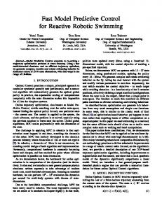
We examine the prospects and the possibility of effective use of the Platonic solids as universal bases to design for adaptive intelligent spatial parallel mobile modular robots. It is well known that only Platonic solids (tetrahedron, cube, octahedron, dodecahedron and icosahedrons) are regular polyhedrons (Fig. 1). Therefore, the modules based on the Platonic solids versus other polyhedrons contain the same elements and they can to unlimitedly build up along any of the faces.
Index Terms—Parallel robot, Platonic solids, self-moving robot, self-reconfigurable robot, swarm systems, modular robot
I. INTRODUCTION
T
HE concept of the modular robotic system has attracted attention over several decades. Modular robotic system consists of homogeneous modules which have combined into a single multilink design, and the connection of these modules allows you to create different structure of the mechanisms [1-4]. Such modules can have an invariable shape (module of serial robot) and a spatial parallel structure with variable geometry of shape (spatial parallel robot of modular type) [5]. The spatial parallel robots versus serial robots have the following main advantages: much higher accuracy and rigidity, higher productivity and reliability, much less sensitive to scaling effect, and ability to manipulate large loads. Compared to the serial robots, the main drawback of hexapods is the smaller workspace [5]. Mobile robots have an unlimited workspace. This may well be reason for the development of their applications [6].
Manuscript received March 13, 2014. This work was supported in part by the Russian Academy of Science, within Program 15 of Fundamental scientific research 2012-2014. S. Sayapin is with the Department of Vibration Biomechanics, Institute for Machine Science named after A.A. Blagonravov of the Russian Academy of Science, 4 Maly Kharitonyevsky Pereulok, Moscow, 101990, Russia (corresponding author to provide e-mail: S.Sayapin@ rambler.ru). A. Karpenko is with the Department of CAD, Bauman Moscow State Technical University, 2-nd Baumanskaya, 5, Moscow, 105005, Russia (email:
[email protected]). H. Dang is with the Department of CAD, Bauman Moscow State Technical University, 2-nd Baumanskaya, 5, Moscow, 105005, Russia (email:
[email protected]).
ISBN: 978-988-19253-5-0 ISSN: 2078-0958 (Print); ISSN: 2078-0966 (Online)
Fig. 1. Platonic solids: f – face; v – vertex; e – edge; n -number of edges per face; m - faces at each vertex.
This paper introduces and outlines the capabilities of a robotic mechanisms based on the Platonic solids where each rib of the can be varied in length. Each of its faces can clamp (unclamp) things with a closed loop surface of various form. These properties open new possibilities for its applications in various fields. Frames with tetrahedral and octahedral forms have the highest rigidity, and a the frame with a cubic form has the lowest rigidity. Frames with dodecahedral and icosahedral forms are of medium rigidity. The tetrahedron and octahedron have the least amount of vertices and edges. Tetrahedral modular robot compared with octahedral robot has less functionality. It is shown that the octahedron is the most perspective modular structure. The octahedral module is a new concept of parallel spatial mechanism with twelve degrees of freedom (d.o.f.). It is an adaptive parallel spatial self-moving modular robot for individual and collective (swarm systems) uses in various fields robotics. The paper describes design principles for our modular robots, called Dodekapod robots (DR), as future intelligent building blocks for various robotic systems that can self-move and self-reconfigure. Such robot versus hexapod with 6 d.o.f. [7] has the larger workspace. Every one of its triangular faces is formed by linear drives that are connected with vertices of octahedron by spherical joints WCE 2014
Proceedings of the World Congress on Engineering 2014 Vol II, WCE 2014, July 2 - 4, 2014, London, U.K.
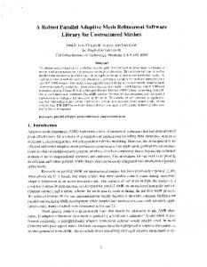
(link balls). These faces can clamp/unclamp a thing with a closed loop surface of various form as well as put pressure on environmental surface of contact. DR is modern stage of development in the field of spatial parallel robots [7]-[8]. Currently, many modern multifunctional concepts are needed to expand functional capabilities of DR. References [8]-[10] shows novel functional capabilities of DR, such as the self-movement, the diagnostics of contact surfaces, and other ones. References [7], [10] show kinematics analyses of dodekapod manipulator. First time carried out a study of algorithms for movements of DR in the pipes of constant and variable cross-sections. We aim at merging technologies from information technology, special requirements in various branches industry, e.g. methods of transportation, space engineering, swarm robotics, rehabilitation medicine, spatial active vibration protection systems and robotics in order to design adaptive and intelligent robots. New functionality of DR is represented below. II. DESCRIPTION OF DODEKAPOD ROBOT We present novel concept of the adaptive parallel spatial self-moving modular robot, called Dodekapod robot, where we aim at merging technologies from information technology, special requirements in various branches industry, e.g. rehabilitation medicine, space engineering, methods of transportation, spatial active vibration protection systems and robotics in order to design adaptive and intelligent robots. DR is an octahedral parallel spatial mechanism. Every one of its triangular faces is formed by linear drives that are connected with vertices of octahedron by spherical joints. This feature opens new functionality of DR versus a hexapod and others parallel spatial robots. The schematic view of the monomodule DR (a) and the simplified structural scheme of the control system (b) are shown in Fig. 2. The structural scheme includes maximal number of sensors, radial stops and grippers. This number is dependent on the applications and it may be decreased. DR is executed as the octahedral module 1. All ribs of the octahedron are executed as the rods with the linear drives 2 each of which have the axial force sensor 3, the medial force sensor 4, the relative displacement sensor 5, and the relative velocity sensor 6. The ends of the adjacent ribs are connected by the spherical joints in the points of octahedral module 7 of the octahedral module 1. The points of octahedral module 7 contain the radial stops and the middles of the rods contain the grippers (on Figure were not shown) each of which have the temperature sensor 8. The octahedral module 1 has 12 d.o.f., which is a spatial farm as soon as all linear drives 2 are turned off. All points of octahedral module 7 have the spatial position sensors 9 which are integrated with the three-axial acceleration sensors 10. The control system (CS) 11 includes: the neural computer 12, the software 13 and the digital-analog converter (DAC) 14. The inputs of CS 11 are connected to outputs of the analogdigital converter (ADC) 15 of sensors 3 and 4, ADC 16 of sensors 5, ADC 17 of sensors 9 and 10, ADC 18 of sensors 6, and ADC 19 of sensors 8. Outputs of CS 11 are connected to inputs of the software 13 and DAC 14. The outputs DAC 14 are connected to the power amplifier 20 which is connected to each of the linear drives 2. ISBN: 978-988-19253-5-0 ISSN: 2078-0958 (Print); ISSN: 2078-0966 (Online)
The octahedral module 1 may be used as a base element not only at the monomodule DR, but also at the
Fig. 2. Octahedral module of adaptive mobile parallel spatial robot (a) and its structure (b).
multimodule ones. The radial stops and the grippers (on Fig. 1 were not shown) provide the transmission of the efforts from linear drives toward the internal and external contact surfaces. The force sensors 3, 4 and temperature sensors 8 provide the operative control of these efforts and temperature in the contact places. The spatial position sensors 9 with three-axial acceleration sensors 10 provide the operative control of the spatial position of points of octahedral module 7 and of vibration along each of axes of rods with linear drives 2. The relative displacement sensors 5 and the relative velocity sensors 6 of the linear drives 2 register their relative movements and velocities. Before using it we will have to place the octahedral module 1 in the inside or the outside of the closed surface and then carry out the necessary movements depending on requirement. The linear drives 2 and the CS 11 fulfill herewith the coordinated changes of the rib lengths of the octahedral module. As a result the points of octahedral module 7 have got spatial movement concerning a base system of coordinates. A geometrical invariability of the octahedral module 1 allows to define the spatial coordinates of all points of octahedral module 7 as a result of the measurement of the lengths of all rods and to control their spatial movements like as in Stewart's platform [11]. The sensors of the spatial position 9 allow herewith elevating a precision of these measurements. The neural computer 12 and the software 13 provide the control of real time. The conditions and the algorithms for movements of DR in straight pipes of constant and variable cross-sections (Fig. 2) are represented below. III. THE ALGORITHMS FOR THE MOVEMENTS OF DODEKAPOD ROBOT IN THE PIPES OF CONSTANT AND VARIABLE CROSS-SECTIONS A. Basic parameters of Dodekapod The dodekapod (Fig. 3, a) contains 6 spherical joints (vertices A, B, C, D, E, F) and 12 rods (ribs AB, BC, AC, DE, EF, DF, AD, AE, BD, BF, CE, CF) with linear drives. The vertices A, B, C and D, E, F form two parallel triangular faces (ABC and DEF). The vertices A, B, C and D, E, F are dodekapod’s stops for a moving in the pipe. When one of the faces in the pipe is fixed, the other face moves by simultaneous changes in the lengths of rods AD, WCE 2014
Proceedings of the World Congress on Engineering 2014 Vol II, WCE 2014, July 2 - 4, 2014, London, U.K.
AE, BD, BF, CE, CF (Fig. 3, b). It is assumed that during the motion dodekapod no slippage between stops and the pipe. Basic notations (Fig. 3, a, c): l0, lm - the minimum and maximum lengths of the rods of dodekapod; δ - the diameter of the spherical joints of dodekapod; lS – the rod lengths of faces ABC and DEF at the time of contact their vertices with the inner surface of a pipe;
5) The reduced length of rods DE, EF, DF from ls to l0. 6) The increased length of rods AD, AE, BD. BF, CE, CF from l0. to lm. 7) The increased length of rods DE, EF, DF from l0 to ls. 8) A repeat of steps from second to seventh. C. The Algorithm for the Movement of Dodekapod in
Fig. 4. The algorithm for the movement of the dodekapod in pipe of constant cross-section.
Pipe of Variable Cross-Section Regarded pipe has three sections (Fig. 5). Two extreme sections have constant cross section (diameters D, d and lengths L1, L2), and the middle section has a variable crosssection (length Δ). The complexity of the problem is the possibility of collision of dodekapod with the inner wall of pipe in transition. It is therefore necessary to determine the ratio between the radii of the platform base and the steps of movement. The conditions for the movement in the transition: ls is in
Fig. 3. Structure and basic notations of dodekapod in pipe constant crosssections.
Hmin - the minimum distance between the faces ABC and DEF (the length of the side rods reaches the minimum length); Hmax - maximum distance between the faces ABC and DEF (the length of the side rods reaches the maximum length); hs - step of the movement of dodekapod, l0