several levels of voltages [1],[4-5].[8],[11]. There are three well- known topologies; diode-clamps, flying capacitor, and cascaded multilevel inverter (CMLI) [2],[5] ...
International Journal of Computer Applications (0975 – 8887) Volume 10– No.6, November 2010
Universal Algorithm Control for Asymmetric Cascaded Multilevel Inverter Bambang Sujanarko
Mochamad Ashari
Mauridhi Hery Purnomo
Dep. of Elect. Eng., Universitas Dep.of Elect. Eng., Institut Teknologi Dep.of Elect. Eng., Institut Teknologi Jember, currently toward Doctor in Sepuluh Nopember (ITS) Surabaya, Sepuluh Nopember (ITS) Surabaya, Institut Teknologi Sepuluh Nopember Indonesia Indonesia (ITS) Surabaya, Indonesia
ABSTRACT Asymmetric Cascaded Multilevel Inverter (ACMLI) was widely studied. Various control strategies have been investigated. However, most of the reported control strategies not discussed how to determinate voltage levels, firing angle, switching-state and other parameters control design. This work was developed a universal algorithm to overcome the problems in the various number of H-Bridges and various DC voltages of ACMLI. The proposed algorithm based on combination theorem and matrix operation. The MATLAB computer program and simulation using MATLAB SIMULINK in the binary, trinary, equal interval, sine quantization and random DC voltage are the methods for verify the proposed algorithm. The results program execution and simulation in the single phase of ACMLI show that the proposed algorithm produces ACMLI control more accurate and faster if compared with previous control strategies.
quantization [3]. To implement ACMLI in the various DC voltage progressions and various numbers of H-Bridges, the main problem is control design that consist some control parameters, especially voltage levels, firing angle and switching-state, because nothing researches reported how to determine these parameters. . S21
S11
+ + -
Vo,1 -
General Terms
Vdc,1 S41
S31
S22
S12
+
Algorithms, Control, Power Electronics
+ -
Vo,2 -
Keywords universal algorithm, asymmetric multilevel inverter, voltage levels, firing angle, switching-state.
Vdc,2 S42
Vo
S32
1. INTRODUCTION Recently the multilevel inverter (MLI) is the most popular dc to ac converters topology for high voltage and high power in the power industry. The MLI synthesize a sinusoidal voltage from several levels of voltages [1],[4-5].[8],[11]. There are three wellknown topologies; diode-clamps, flying capacitor, and cascaded multilevel inverter (CMLI) [2],[5],[7],[9-10]. CMLI had many advantages than others, especially in reduced component, reduced power loss, reduced power stress, reduced frequency switching, reduced electromagnetic interference, increase voltage and power capability and increase power quality [1],[4],[5].[8],[10-11]. In the early development, all of H-Bridge inverters of CMLI have same voltage, and called equal or symmetric CMLI (SCMLI). But in order to improve power quality with provides a large number of output levels without increasing the number of inverters, unequal DC voltages or asymmetric cascaded multilevel inverters (ACMLI) built, where each H-Bridge inverters have different voltages [10]. These voltages can be followed a certain function [4]. The most popular asymmetric CMLI that follow functions are binary (orde-2) and trinary (orde-3) progressions of DC voltages. Others DC progression are equal interval [6] and sine
S2N
S1N
+ + -
Vo,N -
Vdc,N S4N
S3N
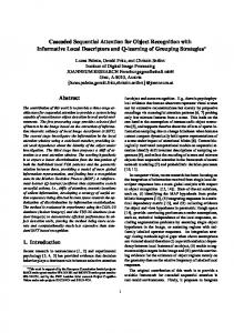
Fig. 1. A Single Phase Asymmetric Cascaded Multilevel Inverter. This paper proposes an algorithm to determine voltage levels, firing angle and switching-states in the ACMLI to overcome the problem. This algorithm based on effective combination and matrix operations that implemented in the m-file MATLAB program. Result this program then fill in the look up table of single phase ACMLI MATLAB SIMULINK circuit. This algorithm verifies in the five cases of DC voltage progressions,
38
International Journal of Computer Applications (0975 – 8887) Volume 10– No.6, November 2010 that is binary, trinary, equal interval, sine quantization and random. Each case investigated in the 2 until 5 numbers of HBridges of ACMLI
and widely vary of the DC voltage used, so count manually will require time, difficult and there are even possible mistakes.
2. STATE COMBINATIONS OF ACMLI Basic circuit of single-phase CMLI is show in the fig. 1. Some power devices such as Insulated Gate Bipolar Transistors (IGBT) can realize the switches. If DC voltages in this circuit are equal, this inverter called SCMLI, otherwise these voltages are unequal, the inverter called ACMLI. Switch combinations and output voltages on each H-Bridge of ACMLI shown in table 1. In this table, 1 indicated ON switch condition and 0 indicated OFF state. Each H-Bridges have four switches, so there are 24 combinations, but only four combinations that available to produce voltages, because other combinations is no connected (NC) conditions that means not produce voltages, or not permitted (NP) conditions that means short circuit occurred. Four available combinations produce three voltages, 0 V, +Vdcj V and –Vdcj V, where j is jth sequence of H-Bridge. The switch combinations that produce 0 V must be choice of two conditions. So, in the each H-Bridges only have three output voltages and three switching-states. Using fig. 1, output voltage could express as (1) [1]. If ACMLI have N H-Bridges, there are many output voltages that produce from (1) with each H-Bridges has three varieties and has switching-states that appropriated on the voltages. Each output voltage occurred in ACMLI called voltage levels. Equation (2) and (3) show the probabilities of voltages and switching-states of ACMLI. The switching-states in equation (3) are only in ON condition.
V o (t )
Vo,1 (t ) Vo, 2 (t ) ..... Vo, N (t )
V0,1 Vo , 2
V0,3 ..... Vo , N ........ Vo , N 1 Vo , N Vo , N 0
Vo
Vo , N
Vo ,1
.Vo , N 1 Vo , N ......... Vo , 2 ..... Vo , N
S 21 , S 31 ; S 22 , S 32 ; S 23 , S 33 ;..... S 2 N , S 3 N .......... S 31 , S 41 ; S 32 , S 32 ;...... S 3 N 1 , S 4 N 1 ; S 2 N , S 3 N S 31 , S 41 ; S 32 , S 42 ; S 33 , S 43 ;..... S 2 N , S 3 N Switching States
S 31 , S 41 ; S 32 , S 42 ; S 33 , S 43 ;..... S 3 N , S 4 N
(3)
S 31 , S 41 ; S 32 , S 42 ; S 33 , S 43 ;..... S1N , S 4 N
(1)
S 31 , S 41 ; S 32 , S 42 ;...... S 3 N 1 , S 4 N 1 ; S1N , S 4 N ......... S11 , S 41 ; S12 , S 42 ; S13 , S 43 ;..... S1N , S 4 N
Table 1. Switch states and output voltage of each H-Bridge Switch states S1j S2j S3j S4j 0 0 0 0 NC 0 0 0 1 NC 0 0 1 0 NC 0 0 1 1 0 0 1 0 0 NC 0 1 0 1 NP 0 1 1 0 -Vdcj 0 1 1 1 NP 1 0 0 0 NC 1 0 0 1 Vdcj 1 0 1 0 NP 1 0 1 1 NP 1 1 0 0 0 1 1 0 1 NP 1 1 1 0 NP 1 1 1 1 NP In Ref. [1] and [4], the voltage maximum and the number of voltage output levels of ACMLI in the binary and trinary DC voltage progression have discussed and result equation (4) until (7). Different DC voltage progression also have discussed in [3] and [6]. But in these reference and others not discussed how to determine switching-states for the voltage levels. The switchingstates usually calculated manually. If there are a lot of H-Bridges
(2)
3. PROPOSED ALGORITHM In this paper proposes an algorithm for determine the voltage levels and switching-state as a new method to solve the above problem. Figure 2(a) show flowchart of this algorithm. The main variables in this algorithm are number of H-bridge and DC voltage of ACMLI.
(2 N 1)Vdc if Vdc, j
Vo, max
Vo, max ( n 2N
n 3N
1
3
N
2
2 j 1Vdc, j 1,2,.... N
(4)
1 )Vdc if Vdc, j 3 j 1Vdc, j 1,2,....N
(5)
2 j 1Vdc, j 1,2,....N
(6)
3 j 1Vdc, j 1,2,....N
(7)
1 if Vdc, j
if Vdc, j
39
International Journal of Computer Applications (0975 – 8887) Volume 10– No.6, November 2010
Build three probabilities voltage output and coding switching-states of each HBridges matrix
Number of H-Bridges Start DC Voltage amplitude
Determine voltage levels combination and their switching codes using matrix operation and iteration.
After determined number of H-Bridges and each DC voltage of ACMLI, the next step is build matrix that consist three probabilities voltage output and coding switching-states of each H-Bridges. Example, if DC voltages are V1, V2, and V3, the voltage output matrix is (8) and the coding switching-state matrix is (9). V=[-V1, -V2, -V3, V1, V2, V3, 0, 0, 0]
Sort matrix and put one of the voltage levels that equal amplitude and their switchingstates
End
Decoding switching-states and construct voltage level and switching-states matrix
(a) Flow Chart % Build three probabilities matrix V=[-1*Vdc1 -1*Vdc2…-1*VdcN…Vdc1 Vdc2...VdcN 0 0… 0]; Q =[N123…2123 1123 N914….2914 1914 N034… 2034 1034];
(8)
Q=[3123,2123,1123,3914,2914,1914,3034,2034,1034] (9) The third step is determined of voltage levels combination and their switching codes using matrix operation. In this step, each HBridges only can be presented in one voltage, while others must be eliminated. Example, using (8) and (9) if H-Bridge 1 is in the – V1, so voltage matrix becomes (10) and switching-state matrix become (11). V matrix remains 7 elements, and so Q matrix. Applying the procedure in all of H-Bridges using iteration program, and use (1) and also use recording of switching states, we can determine all of probability voltage levels and switching states.
% Determine combination Vx1=0;Vx2=0;Vx3=0;Vx4=0;….VxN=0; for i1=1:3*N;
V=[-V1, -V2, -V3, V2, V3, 0, 0]
(10)
Q=[3123,2123,1123,2914,1914,2034,1034] (11)
………
The fourth step is sort result previous step and put one of the voltage levels that equal amplitude. Finally, the switching-states decode in the 1 (ON) or 0 (OFF) state as trigger signal for power electronic devices.
if i1