Unsupervised calibration of RGB-NIR capture pairs utilizing dense multimodal image correspondences Filipe Gama Tampere University of Technology Tampere, Finland
[email protected]
Mihail Georgiev Tampere University of Technology Tampere, Finland
[email protected]
Abstract—In this paper, we propose an unsupervised calibration framework aimed at calibrating RGB plus Near-InfraRed (NIR) capture setups. We favour dense feature matching for the case of multimodal data and utilize the Scale-Invariant Feature Transform (SIFT) flow, previously developed for matching samecategory image objects. We develop an optimization procedure that minimizes the global disparity field between the two multimodal images in order to adapt SIFT flow for our calibration needs. The proposed optimization substantially increases the number of inliers and yields more robust and unambiguous calibration results. Keywords—NIR, calibration, SIFT flow, multimodal stereo, features matching.
I. INTRODUCTION Retrieving geometrical information from a 3D visual scene is required in a wide range of multimedia applications aimed at providing immersive visual experience, such as virtual view synthesis and 3D scene reconstruction. Typically, the scene is captured through stereo or multi-camera rigs, or multimodal sensor setups in which active range sensors e.g. Time-of-Flight (ToF) or laser scanners are used. In all settings, the cameras position in relation to some coordinate system and the relative pose between cameras are essential for the correct 3D geometry retrieval and depth estimation. This process is often subject to extensive calibration procedures, aimed at establishing correspondences between 2D image points and 3D world points. ToF sensors provide real-time depth estimation by measuring the scene response to an emitted light signal. Typically, the light emitter operates in the Near-InfraRed (NIR) wavelength region (~850 nm), which imposes limitations to the sensor regarding size, field-of-view and spatial resolution. As a result, the join calibration between colour and ToF (or any NIR) sensors become more challenging. Similarly to conventional stereo calibration, multimodal calibration setups are categorized as supervised and unsupervised. In the former, the 3D world points are acquired by means of a structured pattern (e.g. checkerboard) while the latter rely only on the detection of invariant scene features. By imposing structural and planarity constraints, the supervised methods yield stable and accurate results in general, for the price of extensive and tedious routines [1], [2], which in some cases may not be applicable. Unsupervised methods rely on finding correspondences between the two modalities [3], [4], [5], and while less accurate in general, they are preferred in cases when the user should be
Atanas Gotchev Tampere University of Technology Tampere, Finland
[email protected]
given an automatic calibration tool with no further requirements regarding the scene. In this work, our goal is to improve and adapt the standard unsupervised stereo camera calibration based on features matching [6] to an RGB-NIR couple setup. We deal with feature matches across RGB and NIR images, which is challenging due to their difference in image properties. In the literature, there are several variants of the classical Scale-Invariant Feature Transform (SIFT) descriptor adapted to NIR imaging [7], [8]. Some of them use multispectral images around the NIR band in order to extract more features from the scene due to changes of material reflectivity, while others account for a single NIR band. In general, feature descriptors are divided into two categories: they either provide sparse representations or dense representations [9]. In sparse representations, it is difficult to define where the feature matches are spawn and this makes the matching between images less accurate. On the other hand, dense feature matching offers a dense flow field that increases the robustness of the estimation of epipolar geometry [9]. Moreover, they do not create gross outliers i.e., arbitrary image locations that are wrongly matched across the whole image plane because of the combination of robust data constraints and global smoothness assumptions [10], [11], [12]. The method in [10], cast as SIFT flow, has been primarily designed to align images with same object category and has been then extended to other applications requiring image alignment. However, its potential for calibration purposes has not been explored yet. We develop an unsupervised calibration framework based on SIFT flow aimed at RGB-NIR sensor pair. We propose modifications, which utilize the pros of the underlined method and tackle its drawbacks. The rest of the paper is organized as follows: Section II introduces our framework and contributions to previous works. In Section III, we describe the experimental setup and present our results. Finally, conclusions are given in Section IV. II. RGB-NIR CALIBRATION FRAMEWORK A. Problem Formulation In this work, we are interested in an unsupervised calibration of a RGB-NIR sensor pair where each device assumes the pinhole model [13]. A pinhole camera is described by intrinsic parameters, including focal length – ( , ) , field-of-view angle – ( , ) , principal point – ( , ) , sensor size in pixels – ( , ) and optical center – , combined in the camera matrix :
=
( , )
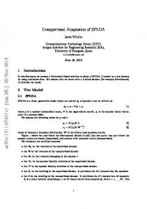
. , ( , ) = ( , ) tan 0 (1) 0 0 1 In the scope of this work, we assume square pixels, i.e., = = and skew coefficient = 0, which is valid for most contemporary cameras. The model relates a 3D points = ( , , ) and its 2D image coordinates = ( , ) by the projective equation [13]. For simplicity, radial and or decentering distortions introduced by optics are not considered here. However, when such case is considered, the projected points are typically compensated through the well-known Brown-Conrady model [14]. The projective equation is: (2) =λ , 1 1 where λ is an unknown scalar factor. The projection matrix of the ideal pinhole camera is defined as follows: ] , (3) = [ |− where the rotation matrix describes the orientation of the camera coordinate system with respect to the world coordinate axes and denotes the position of the camera centre in world coordinates. For a static setup, we place the origin of the world coordinate system (WCS) to one of the two camera coordinate systems, as shown in Fig. 1. For the orientation of the cameras, it is convenient to represent the rotation matrix in terms of pitch-roll-yaw angles ( , , ): ( , , )= ( ) ( ) ( ) , (4) where , , are rotations about the -, - and - axis, respectively.
Fig. 1. Stereo camera system. The world coordinate system (WCS) lies on the same coordinate system than the left camera.
Along this paper, we denote variables of left and right camera or image with subscripts and , respectively. Thus, the projection matrices and of the two cameras are defined according to Fig. 1 as: = [ |− ] (5) = [ |− ] (6) with (0,0,0) = , = (0,0,0) , (7) ( , , ), =( , , ) . (8) where is the identity matrix and ( , , ) are the world coordinates describing the position of the right camera in relation to WCS. The stereo setup is thus fully described by the camera matrices and and six extrinsic parameters describing the orientation ( , , ) and location ( , , ) of the right camera. We assume that the camera matrices are known for each camera (i.e. semi-calibrated stereo pair) and therefore, one can estimate the relative pose of the cameras using the essential matrix (9) = .
It has five degrees of freedom (rotation and translation), while the more general fundamental matrix has seven degrees of freedom and is better suited for intermediate computations regarding calibration. B. Dense Features Representation We favour the use of dense feature representations over sparse ones and base our framework on SIFT flow [10]. For the sake of simplicity, we split our approach into two main parts as shown in Fig. 2. RGB features
RGB image
SIFT features extraction
NIR image RGB matched points NIR matched points
Output calibration data
NIR features
SIFT Flow Optical flow matching
RGB matched points NIR matched points
Relative pose estimation
Local entropy filter & thresholding
Genetic algorithm optimization
Filter points
Convex optimization
Select inliers ( )
Unproject points to original grid
Output calibration data
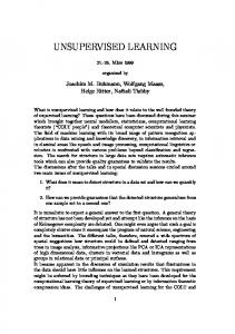
Fig. 2. Calibration algorithm scheme: general scheme (top); relative pose estimation scheme (bottom).
The top part of Fig. 2 shows the general calibration process where features are extracted and matched across RGB and NIR images using SIFT flow. It provides a dense pixel-to-pixel correspondence between two images by properly matching SIFT features. The SIFT flow algorithm may be divided into two main parts: features extraction and features matching. In SIFT features extraction, the neighbourhood (e.g., 16x16) of every pixel in an image is divided into a 4x4 cell array and the orientation is quantized into 8 bins for each cell. In total, SIFT is represented for each pixel as a 4x4x8=128-dimensional vector. Due to the different spatial characteristics and gradient directionality changes, some authors have shown the potential of making SIFT also robust against these observations [12], [15]. In terms of gradient directionality, this is referred as GradientDirection Invariant SIFT (GDISIFT) [15]. After having a per-pixel SIFT descriptors for RGB and NIR images, the second part of SIFT flow is intended to build a dense correspondence of the descriptors by matching them along flow vectors. In this regard, the authors in [10] designed an objective function similar to optical flow in which SIFT descriptors are matched along the flow vectors and the flow field is assumed to be smooth with discontinuities around objects boundaries. The function is defined as: ( ) = ∑ min ( )− (10) + ( ) , + ∑ (| ( )| + | ( )|) + (11) ∑( , )∈ min( | ( ) − ( )|, ) + (12) min( | ( ) − ( )|, ) , where and are the SIFT images (extracted features) from the previous stage, and are the grid coordinates ( , ) for each SIFT image, is a set containing all the spatial neighbourhoods (a 4-neighbour system), and are thresholds to account for matching outliers and flow discontinuities, and are coefficients related to the regularization term and displacement term, and ( ) is the flow vector at that depends on the horizontal flow ( ) and vertical flow ( ). This energy function contains three terms: a data term, a small displacement term, and a smoothness term (a.k.a. spatial regularization). The first term constrains the SIFT descriptors to be matched along with the
flow vector ( ). The second term constrains the flow vectors to be as small as possible when no other information is available. The third term constrains the flow vectors of adjacent pixels to be similar. Unlike in the typical formulation of optical flow, the last term is decoupled in order to decrease the complexity of the algorithm by making use of a sequential belief propagation (BPS). However, since BP-S scales poorly with respect to the image dimensions, the authors designed a coarse-to-fine SIFT flow matching scheme. The coarse-to-fine strategy does not only decreases the computational complexity but also achieves better matching results. SIFT flow performs best when there is a significant overlap between images. Under this condition, and as shown in [10], it achieves better results than sparser representations. For relatively big displacements (small overlap areas), or due to variations in the image such as 3D misalignments and multi sensors, the performance of SIFT flow decreases. Specifically, for large search windows aimed at handling large location changes, it fails to provide reliable matches. As a result, the accuracy of the estimated camera parameters decreases. C. Proposed Calibration Framework In order to address the issue mentioned above, we first minimize the disparity field between the two input images or in simple terms, we try to fit one image into the other. This is achieved through a Genetic Algorithm (GA) optimization combined with SIFT flow as shown in Fig. 2. Before this optimization block, some of the matched points are excluded based on a local entropy filter and thresholding. The local entropy filter provides statistical information about the correlation between one pixel and its neighbourhood in a 9x9 window. This allows us to identify for instance homogenous (texture-less) regions across the image. These regions are then discarded based on a certain predefined threshold value because they are irrelevant to feature descriptors and they usually lead to inaccurate matches [16]. In the GA optimization, the goal is to minimize the disparity field or global disparity by searching for the best combination of ( , , ) and translation vector the rotation matrix = ( , , ) such that ( , , ) ∈ [− /36, /36] and ( , , ) ∈ [−0.05,0.05] . In this case, since we may know roughly the expected displacement (e.g., baseline between cameras), our initialization can be such that the solution may be “seeded” in regions where optimal solutions are likely to be found and therefore, GA may converge faster. One could also set these intervals to greater ranges, i.e., bigger displacements but GA takes more time to converge. Our cost function for GA optimization is defined as: (13) = min ∑ ‖ ( ) + ( )‖ . After iterations, and when no further improvement of the objective function is observed, the GA outputs the best minimum global displacement founded. The next step in our calibration scheme is to filter the features founded for the minimum global displacement. This filtering stage is similar to the one described in [17]. We discard some matched features based on the following steps: (1) Boundary filter – excludes feature points nearby image edges. This ensures that outliers relaying on non-mutual image data among views are removed. (2) Local region filter – discard features that are located very close to each other in both images. (3) Distance
match filter – excludes matched features that present big distances relative to all the others. (4) Intersection filter – removes matched features that intersect many others. (5) Global filter – applies a global least-squares approach for estimating the fundamental matrix and discard matched features that are relatively far from epipolar lines. After filtering the matched features, the points are projected onto the original grid. Note that our goal is to estimate the relative pose between the original images and therefore, the points estimated after GA optimization no longer coincide with the original grid. Once we have established the matches between the original images, the fundamental matrix is estimated through an 8-point algorithm [13]. This is more preferable than directly estimating the essential matrix , even though the camera matrices and are assumed to be known, as the quality and unambiguity of or estimation strongly depend on the location and precision of the matched points, their number, and the number of outliers. Robust solutions require some steps such as feature normalization, extensive search of outlier-free set of correspondences by Random Consensus Search-type approaches (e.g., RanSAC), non-linear optimization search (e.g., Levenberg-Marquardt iteration method), etc. In our case, we make use of RanSAC to discard potential outliers. Finally, the last block of our calibration scheme consists of estimating the relative pose based on the inlier points extracted in the previous stage. This requires knowledge of and decomposing it in terms of rotation and translation via QRdecomposition or Singular Value Decomposition (SVD). is derived from addressing also the scaling issue. The relative pose is found through a convex optimization scheme where the cost function is defined as: = min ∑ d − +d − ℎ : (14) = ∀ , ( , , )∈ − , , ( , , ) ∈ [−0.05,0.05] . In the cost function above, denotes the current point, d(. ) is the Euclidean distance, and are the corresponding points in the first and second image, respectively, and and are = the perfectly matched points that satisfy the constraint ∀ , where is a planar homography matrix. Our solution ( , , ) and provides the best = ( , , ) combination that meets the global minimum. III. EXPERIMENTAL SETUP In this section, we present and discuss experimental results using the benchmark dataset provided by [7], our own synthetic scenes, and some data captured with Kinect v2 which provides RGB, NIR and depth map data. The dataset in [7] was captured using two unsynchronized cameras with filters aimed to separate the visible spectrum and the NIR spectrum. All provided RGBNIR images are distortion-free images and most of them are registered. We used some of them to test our matching method under different rotations and translation values, by applying a projective transform to one of the images. The Kinect v2 data was used as an example of a real use case scenario. In this case, it was necessary to address some additional challenges including distortions, systematic and non-systematic measure errors in the
depth map, and different FoV and spatial resolutions between RGB and depth map/NIR images. A. Model of Misaligned Stereo Setup We assume similar cameras i.e., left and right camera have the same camera matrix = = and assume no image distortions caused by lens aberration. We simulate misalignment between cameras, by defining a relative pose in terms of rotation matrix and baseline vector . The left camera is placed in the world origin and we write the forward projection as: = , where = [ | 0]. The right camera is then modelled as: = , where = − . By applying these projections, we render a new camera view at the desired position. An example is shown in Fig. 3. This simulation transforms the original data with no depth information and therefore has some limitations. For instance, it cannot compensate for spatial changes including parallax, which exists in real stereo cases.
a)
b)
c)
Fig. 3. Example of transformed dataset: a) original RGB image; b) original NIR image; c) transformed NIR image.
B. Matching and Pose Recover for Benchmark Dataset In this first experiment, we aim at evaluating the matching performance and the relative pose estimation of our method against others, including, SIFT [18], SURF [19], KAZE, [20], SIFT flow [10], and NRDC [11]. Thus, we first extract the features using sparse and dense algorithms and then, without any optimization procedure, we estimate the essential matrix and decompose it in terms or rotation and translation. Then, also without any refinement, we evaluate the methods in terms of rotation and ( , , ) and translation standard deviation. The input = ( , , ) are generated randomly such that( , , ) ∈ [− /36, /36], ( , , ) ∈ [−0.05,0.05]. Table 1 shows the performance of the methods for five different images given in Fig. 4. These specific images have been selected as they are well rectified and have no temporal differences. For each image, we run 10 simulations for different ground-truth values of and . Each parameter of the sparse feature descriptors was set to achieve an optimal result across the five images. For the NRDC case, we left the default parameters defined by the authors.
Fig. 4. Test images used in the first experiment [#1–#5]: RGB images (top row); NIR images (bottom row).
Overall, our proposed combination of SIFT flow and GA achieves smallest deviation values compared to other methods. As expected, dense representations work better than sparse ones, and with the additional GA optimization in SIFT flow, the results also improve. For the full proposal, the estimated values
are refined even further leading to better results. For some images, NRDC did not work well for the parameters suggested by the authors (denoted by N/A) mainly due to their colour transformation model fitting. TABLE I. ROTATION AND TRANSLATION DEVIATION
Δ deviation from ground-truth values: Set[#]
1
2
0.85,1.19,0.25 19.26,16.07,32.9 0.85,0.99,0.15 SURF 16.6,16,22.62 0.64,0.92,0.12 KAZE 19.5,11.71,28.65 0.88,0.39,0.22 SIFT flow 7.16,15.75,20.13 0.46,0.66,0.08 NRDC 10.15,8.8,42.06 0.57,0.35,0.08 SIFT flow + GA 6.44,9.6,19.5 0.06,0.04,0.06 Proposed 0.14,0.13,0.1
SIFT
0.82,0.75,0.07 11.96,13.7,18.29 0.75,0.94,0.2 15.5,13.5,25.78 0.79,0.84,0.13 16.22,14.96,25.91 0.75,0.52,0.09 8.70,10.69,26.12 0.89,0.79,0.22 17.52,15.24,29.31 0.62,0.48,0.08 8.58,14.27,25.36 0.04,0.03,0.05 0.15,0.12,0.11
Rotation ( , , )[°] Translation ( , , )[
]
3
5
4
0.52,1.20,0.24 1.17,0.81,0.75 0.49,0.27,0.04 21.68,9.55,40.9 16.74,20.5,42.87 5.09,7.82,20.55 0.7,0.99,0.39 0.3,0.26,0.06 0.77,0.81,0.37 17.09,12.54,18.6 15.51,13.16,36.5 3.88,4.69,17.79 0.56,0.77,0.11 0.81,0.88,0.13 0.26,0.17,0.03 13.06,11.2,17.73 16.79,11.69,13.05 2.91,4.36,22.18 0.85,0.45,0.27 0.56,0.87,0.15 0.13,0.05,0.01 7.74,10.47,11.61 18.2,8.79,12.3 1.64,3.20,7.95 0.17,0.02,0.01 N/A N/A 1.72,3.48,18.72 0.55,0.34,0.04 0.57,0.47,0.08 0.14,0.04,0.01 6.01,9.57,12.1 6.01,9.57,12.1 1.48,2.57,7.72 0.02,0.04,0.02 0.02,0.03,0.02 0.02,0.02,0.02 0.11,0.1,0.09 0.11,0.11,0.08 0.09,0.08,0.08
C. Matching and Pose Recover for Synthetic Scene In this second experiment, our goal is to estimate the relative pose between two synthetic views in order to quantify our calibration framework against the ground-truth values. In contrast with the previous case, depth information is available and therefore we are able to correctly transform any point in space, which renders a more realistic scenario. We simulate the RGB and NIR modes by applying some colour filtering and by adding white Gaussian noise. Namely, for the RGB image, we kept only the green and blue channel, while for the NIR image, we kept the red channel. This is due to the fact that NIR is affected mainly by the red wavelength (~750 nm). In this experiment, we have run five simulations for different ground-truth values of and . The overall results are shown in Table 3 in terms of groundtruth deviation. The visual result for the synthetic image using our framework is shown in Fig. 5. TABLE II. ROTATION AND TRANSLATION DEVIATION
Δ deviation from ground-truth values: SIFT
SURF
KAZE
0.19,0.13,0.38 3.9,8.6,7.11
0.21,0.14,0.27 6.1,9.4,8.62
0.11,0.16,0.09 7.21,9.4,8.65
a)
b)
Rotation ( , , )[°] ] Translation ( , , )[ SIFT flow NRDC Proposed 0.08,0.11,0.20 2.64,3.75,1.13
0.14,0.20,0.21 3.15,4.8,4.06
0.04,0.08,0.04 0.15,0.14,0.11
c)
e) f) d) Fig. 5. Result for the synthetic scene: a) synthetic scene; b) filtered RGB image; c) NIR image; d) ground-truth mesh; e) misaligned mesh; f) aligned mesh using proposed method.
D. Real Use Case Scenario In the third experiment, we demonstrate the potential of our algorithm for the case of registering colour and range images. In particular, we register a colour image with a depth map sensed by Kinect v2, using the reflectance (amplitude) mode as a version of an NIR image. Radial and tangential distortion coefficients and camera matrices and for the two sensors were obtained via supervised calibration using a checkerboard. After undistorting the RGB and NIR images, the depth map was enhanced by inpainting to compensate holes [21]. So far, we have
been considering equal-resolution images, in line with the original SIFT flow algorithm [10]. However, Kinect v2 is equipped with a high-resolution RGB sensor (1920x1080 pixels) with a filed-of-view of 84x54 degrees, and a low-resolution depth/NIR sensor (512x424 pixels) with a filed-of-view of 71x60 degrees. For the demonstration purposes, we simply rescaled both the colour and NIR images to 1280x720 pixels by downsampling the RGB image and upsampling the NIR image though spline interpolation. This is suboptimal and an approach for properly handling images with different resolution is currently under research. Still, the results demonstrate quite good alignment being in par with supervised calibration. In Fig. 6, one can visually compare the result of supervised calibration (Fig. 6-d), with our method (Fig. 6-e). [m]
Curie grant agreement No 676401, European Training Network on Full Parallax Imaging.
REFERENCES [1]
[2]
[3]
[4]
[5] a1)
c1)
b1) [m]
[6] [7]
a2)
c2)
b2)
[8] [9]
[10]
[11] d)
e)
Fig. 6. Registration of RGB and depth map. a1) input RGB image; b1) input depth map; c1) input NIR image; a2) undistorted RGB image; b2) undistorted and enhanced depth map; c2) undistorted NIR image. Point cloud with respective RGB values using: d) a conventional supervised calibration method; e) our method.
IV. CONCLUSION In this paper we proposed a new unsupervised calibration framework of RGB-NIR stereo pair based on SIFT flow. Due to the limitations of the original SIFT flow algorithm, we further proposed a genetic algorithm to reduce the global disparity field between the views in order to improve the matching results. Furthermore, we also included some stages of filtering to discard unreliable matches that can potentially lead to inaccurate results. The last part of our framework is composed of a convex optimization scheme where we estimate the relative position between the cameras and at the same time we reduce the reprojection error. Our results suggest that this framework can be useful for various applications in computer vision where unsupervised or self-calibration of a RGB-NIR pair setup is required. ACKNOWLEDGMENT The work in this paper was funded from the European Union’s Horizon 2020 research and innovation program under the Marie Sklodowska-
[12] [13] [14] [15] [16]
[17]
[18] [19] [20] [21]
D. Herrera, J. Kannala, and J. Heikkilä, “Joint depth and color camera calibration with distortion correction”, IEEE Transactions on Pattern Analysis and Machine Intelligence, vol. 34, pp. 2058–64, 2012. A. Staranowicz, G. Brown, F. Morbidi, and G. Mariottini, “Easy-to-use and accurate calibration of RGB-D cameras from spheres”, Proceedings of the 6th Pacific-Rim Symposium on Image and Video Technology (PSIVT), pp. 265–278, 2013. A. Perez-Yus, E. Fernandez-Moral, G. Lopez-Nicolas, J. Gerreiro, and P. Rives, “Extrinsic calibration of multiple RGB-D cameras from line observations”, IEEE Robotics and Automation Letters, vol. 3, pp. 273– 280, 2018. B. Zeisl, and M. Pollefeys, “Structure-based auto-calibration of RGB-D sensors”, IEEE International Conference on Robotics and Automation (ICRA), pp. 5076–5083, 2016. J. Devaux, H. Hadj-Abdelkader, and E. Colle, “Fully automatic extrinsic calibration of RGB-D system using two views of natural scene”, 13th International Conference on Control Automation Robotics & Vision (ICARCV), pp. 894–900, 2014. R. Liu, H. Zhang, M. Liu, X. Xia, and T. Hu, “Stereo cameras selfcalibration based on SIFT”, ICMTMA, vol. 1, pp. 352–355, 2009. M. Brown, and S. Süsstrunk, “Multi-spectral SIFT for scene category recognition”, CVPR, pp. 177–184, 2011. S. Saleem, and R. Sablatnig, “A robust SIFT descriptor for multispectral images”, IEEE Signal Processing Letters, vol. 21, pp- 400–403, 2014. L. Valgaerts, A. Bruhn, M. Mainberger, and J. Weickert, “Dense versus sparse approaches for estimating the fundamental matrix”, International Journal of Computer Vision, vol. 96, pp.212–234, 2012. C. Liu, J. Yuen, and A. Torralba, “SIFT flow: dense correspondence across scenes and its applications”, IEEE Transactions on PAMI, vol. 33, No. 5, 978–994, 2011. Y. HaCohen, E. Shechtman, D. Goldman, and D. Lischinski, “Non-rigid dense correspondence with applications for image enhancement”, ACM Trans. Graph, vol. 30, pp. 70:1–70:10, 2011. X. Shen, L. Xu, Q. Zhang, and J. Jia, “Multi-modal and multi-spectral registration for natural images”, ECCV, pp. 309–324, 2014. R. Hartley, and A. Zisserman, “Multiple-view geometry in computer vision, 2nd edition”, Cambridge University Press, 2004. J. G. Fryer, and D. C. Brown, “Lens distortion for close-range photogrammetry”, PERS, vol. 52, pp. 51–58, 1986. D. Firmenichy, M. Brown, and S. Süsstrunk, “Multispectral interest points for RGB-NIR image registration”, IEEE ICIP, pp. 181–184, 2011. M. Hassaballah, A. Abdelmgeid, and H. Alshazly, “Image features detection, description and matching - image feature detectors and descriptors: foundations and applications”, Studies in Computational Intelligence, Springer, vol. 630, pp. 11–45, 2016. M. Georgiev, A. Gotchev, and M. Hannuksela, “A fast and accurate recalibration technique for misaligned stereo cameras”, IEEE ICIP, pp. 24– 28, 2013. D. Lowe, “Distinctive image features from scale-invariant keypoints”, International Journal of Computer Vision, vol. 60, pp.91–110, 2004. H. Bay, A. Ess, T. Tuytelaars, and L. Gool, “Speeded-up robust features (SURF)”, CVIU, vol. 110, pp. 346–359, 2008. P. Alcantarilla, A. Bartoli, A. Davison, “KAZE features”, ECCV pp. 214– 227, 2012. J. D'Errico, “Inpaint_nans”, MathWorks file exchange, http://www.mathworks.com/matlabcentral/fileexchange/4551-inpaintnans. Accessed April, 2018.