Upper-Bound Multi-Rigid-Block Solutions for Seismic Performance of
Recommend Documents
Oct 22, 2017 - pseudostatic approach, and the cumulative displacement, ... the stability of slopes and can precisely determine effective ... the unknown distributed load on the loaded boundary ... slope with a weak layer, as shown in Figure 1
yapının asıl dinamik karakterlerine göre güncellenmistir. Güncellemeden ..... were extracted from AVT by using Frequency Domain Decomposition (FDD). A 3-D.
dential Code (IRC) (ICC 2000) and its prede- cessors allowing ... (Pardoen et al 2000; Uang 2001) despite the. IRC allowing shear resistance from walls not ..... 471. 1420. 389. 463 cycles to Pmax e. 18. 37. 19. 34. 21. 15. 29. Umax (mm). 2.4.
Office of Statewide Health Planning and Development OSP ...... are exposed, but an unanchored chiller is of concern as it could fall on top of or crush a ..... manufacturing facility loses the use of customized equipment and does not have an.
Jun 2, 2016 - construction, it is primarily intended for seismic retrofit. In contrast to methods ... nine-story infill frame building, Günay et al. (2009) showed that.
Mar 1, 2018 - PBSD will be best utilized for critical facilities or ... Page 8 ...... Unit Residential; and (b) Research occupancies . ...... The Fragility Database is an Excel workbook that is ...... about a single axis with the smallest base dimens
3) Postdoctoral Research Fellow, Department of Civil Engineering, National Taiwan ... depiction of the performance of highway bridges located in the four.
Mar 23, 2017 - when one is interested in asymmetric RCTF buildings whose past ..... accounting for the axialâbending interaction behavior of the wall mem-.
induced undrained permanent slope displacement. ... available shear strength under various cyclic loading conditions (e.g. ... a series of laboratory tests performed to determine the gradation, specific .... on the sliding surface of an infinite slop
Oct 7, 2015 - the IRC manual follows the 1988 FEMA-154 screening guide- lines (ATC .... CP based on FEMA 356 (2000) and FEMA P-58-1 (2012). The.
Jun 2, 2016 - Structures with Examples in Deep Foundations ..... The first case study is on a pile-raft foundation of the coal bunkers located at a coal ash ...
Nov 2, 2006 - The computation of the total elastic wave field allows the sepa- ration of P- and .... display with Seismic Un*x (Forel et al., 2005). Seismic expres ...
Published: 2013-04-17; Corporate author(s): Directorate-General for Research and Innovation (European Commission); Themes: Industrial research and ...
May 6, 2002 - Low and medium rise non-seismic RC frame buildings designed only .... Concrete slabs, with a thickness of 100 mm, are provided at floor levels. ..... IM and of IMs at different levels of EDPs are also plotted beside and above ...
The Fitzgerald Avenue Bridge over the Avon River in Christchurch, New Zealand, will be used as a case study. It is a small-span twin-bridge that has been.
earthquake preparedness and planning and decision making in the region. ... This structural system has relatively performed better in past earthquakes ...
The Simplified Lateral Mechanism Analysis (SLaMa) for the seismic performance assessment of a case study building damaged in the 2011 Christchurch ...
Abstract In this paper we analyze the location performance of the Montana. Regional Seismic Network (MRSN) using the Seismic Network Evaluation through.
building vulnerability assessments are based on damage probability ... The ability of structures to dissipate seismic input energy is related to the ... uncertainty â for example, arising from the evaluation of material properties from ..... Senevi
Keywords GNSS, integer bootstrapping, ADOP, ambigu- ity success-rate. 1 Introduction. There are many ways of computing an integer ambiguity vector a â Zn ...
The paper describes procedures adopted to develop and implement building vulnerability curves to relate damage ratio (defined as dollar loss / replacement ...
In view of the foregoing were elected two residential buildings, the first of them is a tower belonging to the San Martin neighborhood and the other the consortium ...
strength steel tubes (see Fig. 4a), the net section in the tube occurs at the end of the slot cut into the tube to slip over the gusset plate, and the net section of the ...
Upper-Bound Multi-Rigid-Block Solutions for Seismic Performance of
Oct 22, 2017 - pseudostatic approach, and the cumulative displacement, ... the stability of slopes and can precisely determine effective ... the unknown distributed load on the loaded boundary ... slope with a weak layer, as shown in Figure 1. .... B. Weak layer. H d. C. D. E. F. G. Vb,c. Vb,c. Va,b. Va,b. a. a. b.
Hindawi Mathematical Problems in Engineering Volume 2017, Article ID 1985458, 11 pages https://doi.org/10.1155/2017/1985458
Research Article Upper-Bound Multi-Rigid-Block Solutions for Seismic Performance of Slopes with a Weak Thin Layer Gang Zheng,1,2,3 Xinyu Yang,1,2 Haizuo Zhou,1,2 Da Ha,1,2 and Tianqi Zhang1,2 1
School of Civil Engineering, Tianjin University, Tianjin 300072, China Key Laboratory of Coast Civil Structure Safety of Ministry of Education, Tianjin University, Tianjin 300072, China 3 State Key Laboratory of Hydraulic Engineering Simulation and Safety, Tianjin University, Tianjin 300072, China 2
1. Introduction Extensive investigations have been conducted for the stability of slopes with homogeneous soil. However, the presence of a weak thin layer occurs often in practical engineering. This characteristic requires special attention from engineers with regard to the low shear strength of the weak layer, which has an adverse influence on the performance of slopes. Varying methodologies have been employed to estimate the static stability of slopes with a thin layer, including the limit equilibrium method (Fredlund and Krahn [1]), the upper-bound solution method (Huang and Song [2]), and finite element analysis (Griffiths and Marquez [3]; Ho [4]). However, few studies have focused on the seismic stability of nonhomogeneous slopes. Many catastrophic slope failures have occurred because of earthquakes, such as the 2004 Chuetsu earthquake and the 2008 Wenchuan earthquake, highlighting the importance
of addressing the seismic stability of slopes in geotechnical engineering practices. Once the damage of slopes occurs in urban area, a great number of economic losses may occur. The factor of safety of a slope, estimated using a pseudostatic approach, and the cumulative displacement, determined by adopting Newmark’s sliding block method [5], are two commonly used tools to evaluate the seismic stability of slopes. The former provides a simple solution to evaluate the static stability (e.g., Seed et al. [6], Seed [7], and Chen [8]). The latter commonly adopts Newmark’s sliding technique in estimating the cumulative displacement, which provides detailed information for the earthquake process. Compared with the pseudostatic approach, which underestimates the seismic stability (Ling et al. [9]; Michalowski [10]), Newmark’s sliding technique helps to accurately evaluate the stability of slopes and can precisely determine effective reinforcements. Therefore, this method has recently been widely employed to slopes with a single layer of homogeneous
2
Mathematical Problems in Engineering
soil, with and without reinforcements (Chang et al. [11]; Ling et al. [9]; Ling and Leshchinsky [12]; Michalowski and You [13]; Li et al. [14]; He et al. [15]). The extensions of the upper-bound solution to solving geotechnical problems have been explored by Chen [8]. The multi-rigid-block upper-bound solution is advantageous because it is conceptually clear and easily adopted and it satisfies the Mohr-Coulomb yield criterion (Michalowski [16]; Huang and Qin [17]; Huang and Song [2]). In this study, a three-rigid-block “classroom example” is first presented to show how to calculate the cumulative displacements, and a multi-rigid-block failure mechanism is then developed. The proposed failure mechanism is validated using previous studies with respect to the static factor of safety. The critical yield acceleration coefficient of an earth slope is evaluated by employing the pseudo-static method within the limit analysis framework. The influence of strength and geometric parameters on the critical yield acceleration coefficient is discussed. Subsequently, Newmark’s analytical approach is employed to assess the cumulative displacement by considering different real earthquake acceleration records as input motion.
2. Upper-Bound Theorem The method adopted is based on the kinematical theorem of limit analysis. The upper-bound theorem states that the rate of work done by external forces is less than or equal to the rate of energy dissipation in any kinematically admissible velocity field (Drucker et al. [18]). It can be expressed as ∙
∫ 𝑇𝑖 V𝑖 𝑑𝑆 + ∫ 𝑋𝑖 V𝑖 𝑑𝑉 ≤ ∫ 𝜎𝑖𝑗 𝜀𝑖𝑗 𝑑𝑉. 𝑆
𝑉
𝑉
(1)
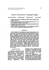
The first term on the left-hand side in (1) is the work rate of the unknown distributed load 𝑇𝑖 on the loaded boundary 𝑆 moving with the given velocity V𝑖 . The second term on the left-hand side represents the work rate of the given distributed forces 𝑋𝑖 in the kinematically admissible velocity V𝑖 . The right-hand side is the rate of the internal work integrated over the entire volume 𝑉 of the collapse mechanism. Based on upper-bound solution, Michalowski and Drescher [19] proposed a class of three-dimensional rotational failure mechanism for the static stability of homogeneous slopes. This failure mechanism was further adopted for analyzing the static stability of slopes with reinforcement (Gao et al. [20]; Zhang et al. [21]; Yang et al. [22]). Different from the rotational failure mechanism for homogeneous slopes, the slip surface passes along the weak thin layer when a weak layer exists (Griffiths and Marquez [3]; Ho [4]) because the weak layer governs the failure mechanism. Huang et al. [23] originally developed a rotational-translational mechanism, which contains three rigid blocks, for a slope with a weak layer, as shown in Figure 1. The velocity of block 𝑏 is V𝑏 , and the angular velocities of block 𝑎 and block 𝑐 are 𝜔𝑎 and 𝜔𝑐 , respectively. An elaborate effort is required as the velocity discontinuities are bent at the interface between adjacent blocks. Zhou et al. [24] proposed a translational failure mechanism to examine the same issue. The rigid rotational blocks 𝑎 and 𝑐 in Huang et al.’s study were replaced
by continuous deformation regions 𝑎 and 𝑐, including a sequence of 𝑛 rigid triangles.
3. Three-Block Failure Mechanism To further establish the multiblock failure mechanism for nonhomogeneous slopes, a three-block failure mechanism acting as a “classroom example” is first presented. More blocks can be incorporated in the failure mechanism to improve the calculation accuracy. Figure 2 illustrates the three-block failure mechanism and velocity hodographs. Based on the normality rule, the direction of the velocities inclines with an angle 𝜑 with discontinuous surfaces, where 𝜑 is the friction angle of the soil in which the discontinuity surface lies. These velocities constitute a kinematically admissible velocity field. The ratio of the incipient velocities of each block is V𝑏 sin (𝜃1 − 2𝜑1 + 𝛼1 − 𝛿𝑤 ) = = 𝐴𝑎 V𝑎 sin (𝜃1 − 𝜑1 − 𝜑2 ) V𝑐 sin (𝜑1 + 𝜑2 − 𝛿𝑤 + 𝛼2 ) = = 𝐴 𝑐, V𝑏 sin (𝜃2 − 2𝜑1 )
(2)
where V𝑎 , V𝑏 , and V𝑐 are the incipient velocities in different blocks, ABCG, CDFG, and DEF, respectively, and 𝜑1 and 𝜑2 are the internal friction angles of the soils, respectively. The angles of 𝜃1 , 𝜃2 , 𝛼1 , 𝛼2 , and 𝛿𝑤 are illustrated in Figure 2. For the assumed kinematically admissible failure mechanism, once the rates of work performed by the external forces and the self-weight of soils exceed the energy dissipation rate, the soil will reach its limit state. The rate of external work due to the self-weight of soils can be calculated as follows: 𝑊𝛾 = 𝑊𝑎 𝛾 + 𝑊𝛾 𝑏 + 𝑊𝑐 𝛾 = 𝑔 [𝑚𝑎 sin (𝛼𝑎 − 𝜑1 ) V𝑎 + 𝑚𝑏 sin (𝛿𝑤 − 𝜑2 ) V𝑏 − 𝑚𝑐 sin (𝛼𝑐 − 𝜑1 ) V𝑐 ] ,
(3)
where 𝑚𝑎 , 𝑚𝑏 , and 𝑚𝑐 are the masses of different blocks and 𝑔 is the gravitational acceleration. Once the earth slope is subjected to horizontal earthquakes, the rate of the inertial force should be considered in the energy balance equation. According to previous investigations (Li et al. [14]; He et al. [15]), the effect of the failure mechanism on the shaking mode can be neglected. The influences of the horizontal earthquakes acting on the collapse mass are evaluated by horizontal forces applied to the center of soil mass, which can be calculated as follows: 𝑊𝑠 = 𝑊𝑎𝑠 + 𝑊𝑏𝑠 + 𝑊𝑐𝑠 = 𝑘𝑔 [𝑚𝑎 V𝑎 cos (𝛼𝑎 − 𝜑1 ) + 𝑚𝑏 V𝑏 cos (𝛿𝑤 − 𝜑2 ) − 𝑚𝑐 V𝑐 cos (𝛼𝑐 − 𝜑1 )] .
(4)
The rate of internal energy dissipation 𝐷𝑐 is induced by soil cohesion in the collapse mechanism. Energy dissipation is calculated as the sum of the rates of dissipation along the discontinuity surfaces, and the blocks move in directions
Figure 2: Three-block failure mechanism for slopes with a weak layer.
that make an angle 𝜑1 or 𝜑2 with the discontinuity surfaces. The energy dissipation along the discontinuity surfaces is the soil cohesion multiplied by the relative velocities and the length of discontinuity surface in the soil mass. To determine the critical yield acceleration coefficient 𝑘𝑐 , at which the slope will be at the limit state, the 𝑘𝑐 value
𝑘𝑐 =
can be calculated by equating the rate of internal energy dissipation to the external rate of work. 𝑊𝛾 + 𝑊𝑠 = 𝐷𝑐 .
(5)
The critical yield acceleration coefficient 𝑘𝑐 can be evaluated as
𝐷𝑐 − 𝑊𝛾 . 𝑔 [𝑚𝑎 V𝑎 cos (𝛼𝑎 − 𝜑1 ) + 𝑚𝑏 V𝑏 cos (𝛿𝑤 − 𝜑2 ) − 𝑚𝑐 V𝑐 cos (𝛼𝑐 − 𝜑1 )]
(6)
4
Mathematical Problems in Engineering
Newmark’s sliding block technique, which was used in a previous study in investigating the performance of slopes under the rotational failure mechanism in both two- and three-dimensional problems (e.g., Chang et al. [11], Li et al. [14], and He et al. [15]), was employed for estimating the cumulative displacement of slopes. The sliding block begins to accelerate with acceleration values 𝑢̈𝑎 , 𝑢̈𝑏 , and 𝑢̈𝑐 ; thus, balancing the work rate equation yields
interval when the seismic coefficient 𝑘 exceeds the critical yield acceleration coefficient 𝑘𝑐 of earth slopes. Based on Newmark’s analytical approach [5], the cumulative displacement can be estimated by integrating the velocity of the failing soil masses, which can be integrated by acceleration. Note that the acceleration herein is a real acceleration rather than the time derivative of the incipient velocity. Subtracting (6) from (7), the acceleration can be expressed as
(7)
− 𝑚𝑐 cos (𝛼𝑐 − 𝜑1 )
+ 𝑚𝑐 V𝑐 𝑢̈𝑐 . + 𝑚𝑐 According to Newmark’s analytical approach (Newmark [5]), the downhill movement of soil was assumed. The direction of soil displacement is not influenced by the direction of the earthquake acceleration. Earthquake acceleration varies during the whole process of shaking. The velocity of the failing masses increases from zero during the time
𝑢̈𝑏 = 𝑔 (𝑘 − 𝑘𝑐 )
V𝑎 + 𝑚𝑏 cos (𝛿𝑤 − 𝜑2 ) V𝑏
V 𝑢̈ V𝑐 ] = 𝑢̈𝑏 (𝑚𝑎 𝑎 𝑎 + 𝑚𝑏 V𝑏 V𝑏 𝑢̈𝑏
V𝑐 𝑢̈𝑐 ). V𝑏 𝑢̈𝑏
To satisfy the kinematical admissibility, the ratios of 𝑢̈𝑎ℎ /𝑢̈𝑏 and 𝑢̈𝑏 /𝑢̈𝑐0 are the same as V𝑎ℎ /V𝑏 and V𝑏 /V𝑐0 (Michalowski and You [13]). This behavior occurs because the deformation of soil is governed by the normality rule. Therefore, the acceleration 𝑢̈𝑏 can be expressed as
Coefficient 𝐶 can be evaluated by the proposed translational mechanism. Additionally, the slope geometries and soil properties are contained in coefficient C, which is involved in the optimization of the proposed collapse mechanism. The horizontal displacement in the toe of slopes can be determined through the analysis of the displacement of any point in the failing soil masses:
(9)
between the incipient velocities of different blocks can be expressed as follows: 𝑘=𝑖 𝑢̈𝑎,𝑖 sin (𝜃𝑎,𝑘 − 2𝜑1 + 𝛼𝑎,𝑘−1 − 𝛼𝑎,𝑘 ) V𝑎,𝑖 = =∏ V𝑎,1 𝑢̈𝑎,1 𝑘=2 sin (𝜃𝑎,𝑘 − 2𝜑1 )
Integration is made over time, which only includes intervals for which the initial integral is positive. The coefficient 𝐶 is related to the geometry of the structure, the soil condition, and the failure mechanism.
4. Multiblock Failure Mechanism A multiblock failure mechanism was further employed based on the previous three-block collapse mechanism. Figure 3 shows the multiblock failure mechanism in which the blocks ABCD and DEF in the three-block failure mechanism are divided into a sequence of discrete blocks. The relations
sin (𝜃𝑏 − 2𝜑1 + 𝛼𝑎,𝑛 − 𝛿𝑤 ) 𝑢̈ V𝑏 = 𝑏 = = 𝐴 𝑎,𝑏 V𝑎,𝑛 𝑢̈𝑎,𝑛 sin (𝜃𝑏 − 𝜑1 − 𝜑2 ) V𝑐,1 𝑢̈𝑐,1 sin (𝜑1 + 𝜑2 − 𝛿𝑤 + 𝛼𝑐,1 ) = = = 𝐴 𝑏,𝑐 , 𝑢̈𝑏 V𝑏 sin (𝜃𝑐,1 − 2𝜑1 ) where 𝑖 = 2, 3, 4, . . . , 𝑛 and 𝑘 = 2, 3, 4, . . . , 𝑖 and V𝑎,𝑖 and V𝑐,𝑖 are the velocities of blocks ABCD and DEF, respectively. The rate of external work due to the self-weight of soils can be estimated as follows: 𝑛
𝑊𝛾 = ∑𝑚𝑎,𝑖 V𝑎,𝑖 sin (𝛼𝑎,𝑖 − 𝜑1 ) + 𝑚𝑏 V𝑏 sin (𝛿𝑤 − 𝜑2 ) 𝑖=1
𝑛
− ∑𝑚𝑐,𝑖 V𝑐,𝑖 sin (𝛼𝑐,𝑖 − 𝜑1 ) . 𝑖=1
(12)
Mathematical Problems in Engineering
5
n
A B
O i
a,1
1
1
H C c1 , 1 D
E
a,i a,i
c,i
d
c,1
c,i w
a,i
F
b
b 2
Weak layer c2 , 2
G
Figure 3: Multiblock failure mechanism for slopes with a weak layer.
The effects of the horizontal earthquakes can be evaluated as follows: 𝑛
𝑊𝑠 = 𝑘𝑔 [∑𝑚𝑎,𝑖 V𝑎,𝑖 cos (𝛼𝑎,𝑖 − 𝜑1 ) 𝑖=1
𝑛
The rate of internal energy dissipation 𝐷𝑐 is estimated as the sum of the rates of dissipation along the discontinuity surfaces in the multiblock failure mechanism. The critical yield acceleration coefficient 𝑘𝑐 can be evaluated as
(13)
+ 𝑚𝑏 V𝑏 cos (𝛿𝑤 − 𝜑2 ) − ∑𝑚𝑐,𝑖 V𝑐,𝑖 cos (𝛼𝑐,𝑖 − 𝜑1 )] . 𝑖=1
𝑘𝑐 =
𝐷𝑐 − 𝑊𝛾 ∑𝑛𝑖=1 𝑚𝑎,𝑖 𝑔V𝑎,𝑖 cos (𝛼𝑎,𝑖 − 𝜑1 ) + 𝑚𝑏 𝑔V𝑏 cos (𝛿𝑤 − 𝜑2 ) − ∑𝑛𝑖=1 𝑚𝑐,𝑖 𝑔V𝑐,𝑖 cos (𝛼𝑐,𝑖 − 𝜑1 )
An additional term induced by inertial forces acting on the failing soil masses when the earthquake acceleration of the ground motion exceeds the critical acceleration of the structure is as follows: 𝛾
𝑛
𝑊 + 𝑘𝑔 [∑𝑚𝑎,𝑖 V𝑎,𝑖 cos (𝛼𝑎,𝑖 − 𝜑1 ) 𝑖=1
𝑢̈𝑏 = 𝑔 (𝑘 − 𝑘𝑐 )
.
(14)
𝑛
+ 𝑚𝑏 V𝑏 cos (𝛿𝑤 − 𝜑2 ) − ∑𝑚𝑐,𝑖 V𝑐,𝑖 cos (𝛼𝑐,𝑖 − 𝜑1 )] 𝑖=1
The above expression indicates that acceleration of a failing structure affects the failure mechanism and the critical yield acceleration coefficient 𝑘𝑐 . The double integral in (10) is needed to be introduced when calculating the displacement.
= 𝑔 (𝑘 − 𝑘𝑐 ) 𝐶.
(16)
5. Validation To validate the proposed multi-rigid-block upper-bound analysis, two well-defined classical slopes with a weak thin
6
Mathematical Problems in Engineering 15 m
6m
15 m
6m
c1 = 20 kPa 1 = 10∘
1 = 45∘ 5m 4m
0.5 m
c2 = 12 kPa 2 = 5∘
2 = 4.76∘
Figure 4: Schematic diagram of slope A. 15 m
12.25 m
20 m
20 m
2 1
c1 = 29 kPa 1 = 20∘
0.5 m
c2 = 0 kPa 2 = 10∘
5m
3.75 m
Figure 5: Schematic diagram of slope B.
2.5
2.0 Factor of safety
layer were selected in calculating the static factor of safety. Figure 4 illustrates the schematic diagram of slope A (Huang et al. [23]). A nonhomogeneous slope A has an angle 𝛽 = 45∘ and height H = 6 m. The soil strength parameters of slopes were 𝜑1 = 10∘ , 𝑐1 = 20 kPa, and a 0.5 m thick weak layer characterized by 𝜑2 = 5∘ and 𝑐2 = 12 kPa. Figure 5 shows the geometric and strength parameters of a nonhomogeneous slope 𝐵 underlain by a thin weak layer, which was previously analyzed by Fredlund and Krahn [1]. A 1 : 2 slope has a height of H = 12.25 m, with soil properties of 𝜑1 = 20∘ and 𝑐1 = 29 kPa and strength parameters of the weak layer of 𝜑2 = 10∘ and 𝑐2 = 0 kPa. The factor of safety computed by the proposed multirigid-block failure mechanism for slope A was first compared with the results obtained by Huang et al. [23] and Zhou et al. [24], as shown in Figure 6. The calculated factor of safety from the multi-rigid-block failure mechanism was equal to the FEM result. The value was slightly higher than the result from Discontinuity Layout Optimization (Zhou et al. [24]) and the upper-bound solution based on the rotationaltranslational collapse mechanism (Huang et al. [23]), but it was better than that of the upper-bound solution based on the translational collapse mechanism. Figure 7 shows the validation of the factor of safety between the upper-bound multi-rigid-block failure mechanism and the results obtained by Fredlund and Krahn [1] and Zhou et al. [24]. Fredlund and Krahn [1] adopted Spencer’s method and Janbu’s rigorous method to evaluate the stability of slope B. The proposed multi-rigid-block failure mechanism yields a factor of safety of 1.34, which is in the vicinity of that between the DLO and analytical solutions. The comparison demonstrated the reasonable consistency with previous studies. The proposed
1.5
1.27
1.28
1.25
1.31
1.28
1.0
0.5
0.0 Upper-bound MIFONCIH; &%- ; $,/<
Upper-bound MIFONCIH< This study
Figure 6: Validation of the results of the static factor of safety (slope A). a: Huang et al. [23]; b: Zhou et al. [24].
multi-rigid-block failure mechanism was then employed to examine the critical yield acceleration coefficient and cumulative displacements of the slopes.
6. Critical Yield Acceleration Coefficient Before evaluating the cumulative displacement under earthquake load, the influence of geometric and strength parameters on critical yield acceleration coefficient was analyzed. This coefficient is the threshold at which the displacement of slopes starts accumulating.
Figure 7: Validation of the results of the static factor of safety (slope B). a: Huang et al. [23]; b: Zhou et al. [24]. 0.25
0.3
0.20 0.2 kc
kc
0.15
0.10 0.1 0.05
0.0
0.00 15
30
45
60
75
1
1 = 10∘ 1 = 20∘
2
3
4
H:B 1 = 30∘ 1 = 40∘
(a) Slope A
1 = 10∘ 1 = 20∘ 1 = 30∘ (b) Slope B
Figure 8: Critical yield acceleration coefficient with various slope angles.
Figures 8, 9, and 10 show the critical yield acceleration coefficients of slopes A and B for various angles, slope heights (H), and depths of the weak layer (d), respectively. Ranges of slope angles (𝛽 = 15∘ –90∘ ) and frictional strength (𝜑 = 10∘ –40∘ ) were analyzed for slope A, whereas slope inclinations of 0.5 : 1 to 4 : 1 and friction angles of 𝜑 = 10∘ –30∘ were estimated for slope B. As expected, the critical yield acceleration coefficient 𝑘𝑐 decreased with the increasing slope angle and slope height, but it increased with the increasing depth of the weak layer. Slope A was more stable than slope B based on the calculated critical yield acceleration coefficient 𝑘𝑐 . Figure 11 presents the critical yield acceleration coefficients of slopes A and B for various soil strengths. A reduction
factor 𝑅 (defined as 𝑅 = 𝑐2 /𝑐1 = tan 𝜑2 / tan 𝜑1 ) was introduced here to show the effect of the soil strength of the weak layer on 𝑘𝑐 value. It is a homogeneous slope when 𝑅 is equal to 1.0. Generally, the critical yield acceleration coefficient 𝑘𝑐 increased with 𝜑1 and 𝑅. Note that there was a critical 𝑅 value existing in slope A, indicating increased 𝑅 was not beneficial to the 𝑘𝑐 value as the collapse mechanism changed to a rotational log-spiral failure mode. Critical 𝑅 value of slope A is greater than that of slope B because the angle of slope A is larger than that of slope B, indicating the rotational log-spiral failure is likely to occur. Figures 12 and 13 illustrate the potential failure mechanism for various friction angles of slope A and slope B at the critical yield acceleration coefficient 𝑘𝑐 , respectively.
8
Mathematical Problems in Engineering 0.25
0.4
0.20 0.3
0.2
kc
kc
0.15
0.10 0.1 0.05
0.00
0.0 5
6
7
8
9
6
10
7
8
H (m) 1 = 30∘ 1 = 40∘
1 = 10∘ 1 = 20∘
9
10 H (m)
1 = 10∘ 1 = 20∘
11
12
13
14
1 = 30∘ 1 = 40∘
(a) Slope A
(b) Slope B
Figure 9: Critical yield acceleration coefficient with various slope heights. 0.4
0.5
0.4 0.3
kc
kc
0.3 0.2
0.2 0.1 0.1
0.0
0.0 0
1
2 d (m)
3
4
1 = 30∘ 1 = 40∘
1 = 10∘ 1 = 20∘ (a) Slope A
0
1
2 d (m)
1 = 10∘ 1 = 20∘
3
4
1 = 30∘ 1 = 40∘ (b) Slope B
Figure 10: Critical yield acceleration coefficient with various depths of the weak layer.
A panhandling failure mechanism partially penetrating the weak layer can be identified in both slopes A and B. For slope A, the failure slip significantly increased when the friction angle was higher than 20∘ compared with slope B. This behavior is due to the inclination of the weak thin layer, which tends to be mobilized in large landslides.
7. Cumulative Displacements The cumulative displacements of slopes with a weak thin layer were calculated through Newmark’s analytical approach. The
real earthquake motion input has a significant effect on the cumulative displacements of the failing soil masses. Therefore, different real earthquake acceleration records were selected to evaluate the cumulative displacements of slopes. Following He et al. [15], three typical earthquake records were adopted. Figure 14(a) shows the Imperial Valley-06 earthquake records, with a peak earthquake acceleration (PGA) of 0.307 g and a record duration of 14.76 s. Figure 14(b) shows the Kobe earthquake record, with PGA = 0.345 g and a record duration of 20 s. Figure 14(c) illustrates the Parkfield-02 earthquake record, with PGA = 0.373 g and a
Mathematical Problems in Engineering
9
0.8 0.8 0.6
0.4
kc
kc
0.6
0.4
0.2
0.2
0.0
0.0 0.2
0.4
0.6
0.8
1.0
0.2
0.4
0.6
R
1.0
R 1 = 30∘ 1 = 40∘
1 = 10∘ 1 = 20∘
0.8
1 = 10∘ 1 = 20∘
(a) Slope A
1 = 30∘ 1 = 40∘ (b) Slope B
Figure 11: Critical yield acceleration coefficient with various strengths of weak clay.
Figure 13: Potential failure mechanism for various friction angles of slope B at the critical yield acceleration coefficient 𝑘𝑐 .
duration of 21.07 s. The constant time intervals of the Imperial Valley-06 and Kobe earthquake records are 0.01 s, whereas the constant time interval of the Parkfield-02 earthquake record is 0.005 s. These earthquake records were used to assess the performance of the slopes with varying slope angles subjected to seismic loads. Tables 1 and 2 list the seismic displacements of slope A and slope B with various slope angles. The maximum horizon displacements of the slopes increased with increasing peak earthquake acceleration of the earthquake motion input. In addition, the cumulative displacement significantly increased with the slope angles.
In this investigation, the seismic performance of slopes with a weak layer is estimated. Based on the upper-bound solution, a three-rigid-block acting as a “classroom example” is first presented, and then a multi-rigid-block failure mechanism is further proposed. The static factor of safety calculated by the proposed method exhibits strong agreement with previous studies. Subsequently, two well-defined cases existing in the available literature are introduced to analyze the influence of soil conditions and geometric parameters on the critical yield acceleration coefficient. Newmark’s analytical procedure is adopted to assess the cumulative displacement. The results show that the failure slip is greatly deepened when the weak thin layer is inclined. The critical yield acceleration coefficient increased with soil strength and depth of the weak layer and decreased with slope angle and slope height. The cumulative displacement of the slope increased significantly with the peak earthquake acceleration. Lastly, the slope angle has a prominent effect on the seismic performance of structures. Note that two-dimensional analysis results in a conservative solution in comparison to three-dimensional method (Tanchaisawat et al. [25]; Ho [26]). Thus, future work will be conducted on the seismic performance of slopes with a weak layer using three-dimensional analysis.
Conflicts of Interest The authors declare that they have no conflicts of interest.
Mathematical Problems in Engineering 0.4
0.4
0.2
0.2 Acceleration (g)
Acceleration (g)
10
0.0
−0.2
0.0
−0.2
−0.4
−0.4 0
5
10
15
0
5
10 Time (s)
Time (s) (a) Imperial Valley-06 earthquake
15
20
(b) Kobe earthquake
0.4
Acceleration (g)
0.2
0.0
−0.2
−0.4 0
5
10 Time (s)
15
20
(c) Parkfield-02, CA earthquake
Figure 14: Acceleration records of selected earthquake.
Table 1: Results of cumulative displacement for slope A with various slope angles. Slope angle 𝛽 𝑘𝑐 𝑢𝑥 (cm) Imperial Valley-06 Kobe Parkfield-02
15∘ 0.155
Slope A 30∘ 0.135
45∘ 0.115
60∘ 0.107
75∘ 0.046
13.15 28.35 37.45
15.77 41.45 49.14
21.28 60.46 62.23
32.31 79.49 88.78
55.23 156.43 166.45
Table 2: Results of cumulative displacement for slope B with various slope angles. Slope B Slope angle 𝛽 𝑘𝑐 𝑢𝑥 (cm) Imperial Valley-06 Kobe Parkfield-02
1:3 0.131
1:2 0.112
1:1 0.076
2:1 0.02
21.84 48.51 55.29
31.44 75.41 76.15
44.89 118.81 120.45
218.88 499.22 581.24
Mathematical Problems in Engineering
Acknowledgments This research was funded by the National Natural Science Foundation of China (Grant nos. 51708405 and 51378345).
References [1] D. G. Fredlund and J. Krahn, “Comparison of slope stability methods of analysis,” Canadian Geotechnical Journal, vol. 14, no. 3, pp. 429–439, 1977. [2] M. Huang and C. Song, “Upper-bound stability analysis of a plane strain heading in non-homogeneous clay,” Tunnelling and Underground Space Technology, vol. 38, pp. 213–223, 2013. [3] D. V. Griffiths and R. M. Marquez, “Three-dimensional slope stability analysis by elasto-plastic finite elements,” G´eotechnique, vol. 57, no. 6, pp. 537–546, 2007. [4] I.-H. Ho, “Numerical study of slope-stabilizing piles in undrained clayey slopes with a weak thin layer,” International Journal of Geomechanics, vol. 15, no. 5, 2014. [5] N. M. Newmark, “Effects of earthquakes on dams and embankments,” G´eotechnique, vol. 15, no. 2, pp. 139–160, 1965. [6] H. B. Seed, K. L. Lee, and I. M. Idriss, “Analysis of the sheffield dam failure,” Journal of the Soil Mechanics and Foundations Division, ASCE, vol. 95, no. 6, pp. 1453–1490, 1969. [7] H. B. Seed, “Considerations in the earthquake-resistant design of earth and rockfill dams,” G´eotechnique, vol. 29, no. 3, pp. 215– 263, 1979. [8] W. F. Chen, “Plasticity in soilmechanics and landslides,” Journal of the Engineering Mechanics Division, vol. 106, no. 3, pp. 443– 464, 1980. [9] H. I. Ling, D. Leshchinsky, and E. B. Perry, “Seismic design and performance of geosynthetic-reinforced soil structures,” G´eotechnique, vol. 47, no. 5, pp. 933–952, 1997. [10] R. L. Michalowski, “Soil reinforcement for seismic design of geotechnical structures,” Computers and Geotechnics, vol. 23, no. 1-2, pp. 1–17, 1998. [11] C.-J. Chang, W. F. Chen, and J. T. P. Yao, “Seismic displacements in slopes by limit analysis,” Journal of Geotechnical Engineering, vol. 110, no. 7, pp. 860–874, 1984. [12] H. I. Ling and D. Leshchinsky, “Effects of vertical acceleration on seismic design of geosynthetic-reinforced soil structures,” G´eotechnique, vol. 48, no. 3, pp. 347–373, 1998. [13] R. L. Michalowski and L. You, “Displacements of reinforced slopes subjected to seismic loads,” Journal of Geotechnical and Geoenvironmental Engineering, vol. 126, no. 8, pp. 685–694, 2000. [14] X. Li, S. He, and Y. Wu, “Seismic displacement of slopes reinforced with piles,” Journal of Geotechnical and Geoenvironmental Engineering, vol. 136, no. 6, pp. 880–884, 2010. [15] Y. He, H. Hazarika, N. Yasufuku, Z. Han, and Y. Li, “Threedimensional limit analysis of seismic displacement of slope reinforced with piles,” Soil Dynamics and Earthquake Engineering, vol. 77, pp. 446–452, 2015. [16] R. L. Michalowski, “Displacements of multiblock geotechnical structures subjected to seismic excitation,” Journal of Geotechnical and Geoenvironmental Engineering, vol. 133, no. 11, pp. 1432– 1439, 2007. [17] M. Huang and H.-L. Qin, “Upper-bound multi-rigid-block solutions for bearing capacity of two-layered soils,” Computers and Geotechnics, vol. 36, no. 3, pp. 525–529, 2009.
11 [18] D. C. Drucker, W. Prager, and H. J. Greenberg, “Extended limit design theorems for continuous media,” Quarterly of Applied Mathematics, vol. 9, pp. 381–389, 1952. [19] R. L. Michalowski and A. Drescher, “Three-dimensional stability of slopes and excavations,” Geotechnique, vol. 59, no. 10, pp. 839–850, 2009. [20] Y. Gao, S. Yang, F. Zhang, and B. Leshchinsky, “Threedimensional reinforced slopes: evaluation of required reinforcement strength and embedment length using limit analysis,” Geotextiles and Geomembranes, vol. 44, no. 2, pp. 133–142, 2016. [21] F. Zhang, D. Leshchinsky, Y. Gao, and B. Leshchinsky, “Required unfactored strength of geosynthetics in reinforced 3D slopes,” Geotextiles and Geomembranes, vol. 42, no. 6, pp. 576–585, 2014. [22] S. Yang, B. Leshchinsky, F. Zhang, and Y. Gao, “Required strength of geosynthetic in reinforced soil structures supporting spread footings in three dimensions,” Computers & Geosciences, vol. 78, pp. 72–87, 2016. [23] M. Huang, H. Wang, D. Sheng, and Y. Liu, “Rotationaltranslational mechanism for the upper bound stability analysis of slopes with weak interlayer,” Computers and Geotechnics, vol. 53, pp. 133–141, 2013. [24] H. Zhou, G. Zheng, X. Yang, Y. Diao, L. Gong, and X. Cheng, “Displacement of pile-reinforced slopes with a weak layer subjected to seismic loads,” Mathematical Problems in Engineering, vol. 2016, Article ID 1527659, 10 pages, 2016. [25] T. Tanchaisawat, D. T. Bergado, and P. Voottipruex, “2D and 3D simulation of geogrid-reinforced geocomposite material embankment on soft Bangkok clay,” Geosynthetics International, vol. 16, no. 6, pp. 420–432, 2009. [26] I.-H. Ho, “Three-dimensional finite element analysis for soil slopes stabilisation using piles,” Geomechanics & Geoengineering, 2017.
Advances in
Operations Research Hindawi Publishing Corporation http://www.hindawi.com