TRANSPORT PROBLEMS PROBLEMY TRANSPORTU
2009 Volume 4 Issue 3 Part 1
Łukasz KONIECZNY, Rafał BURDZIK, Bogusław ŚLEZIAK Department of Automotive Vehicle Construction Faculty of Transport, Silesian University of Technology
ul. Krasińskiego 8, 40-019 Katowice Corresponding author. E-mail:
[email protected]
USAGE OF SHORT TIME FOURIER TRANSFORM IN IDENTIFICATION OF VEHICLE SHOCK ABSORBER TECHNICAL CONDITIONS RESEARCHED BY FORCE VIBRATION METHOD Summary. The paper presents results of vibro-acoustic signal analysis (acceleration of the unsprung mass of passenger’s car suspension actuated to vibration by harmonic, kinematic vibration). The range of research has included front shock absorber for Fiat Seicento with simulated fault (oil leak). Force process consisted of three phases: increase of frequency, vibration with constant frequency (above 21 Hz) and decreases of frequency. For the analysis process Short Time Fourier Transform method was used with superposition of rectangles window and with zero complement method. On STFT spectrum resonance frequency of unsprung mass was identified. The estimator was the means of maximum acceleration amplitude peak in frequency band round resonance frequency. The result of investigation was presented on diagrams with changeable value of estimator for different technical conditions of shock absorber (with different volume of oil inside the shock absorber)
WYKORZYSTANIE STFT W IDENTYFIKACJI STANU TECHNICZNEGO AMORTYZATORÓW ZABUDOWANYCH W POJEŹDZIE BADANYCH METODĄ DRGAŃ WYMUSZONYCH Streszczenie. W pracy przedstawiono wyniki analiz wibroakustycznych sygnałów drganiowych przyśpieszeń drgań mas nieresorowanych zawieszania samochodu osobowego pobudzonych do drgań kinematycznym wymuszeniem harmonicznym. Badania obejmowały amortyzatory przednie zabudowane w samochodzie marki Fiat Seicento z zaprogramowanymi usterkami w postaci ubytku płynu amortyzatorowego. Proces wymuszenia składał się z trzech kolejnych etapów: wzrostu częstości wymuszenia pracy ze stałą częstością oraz z malejącą częstością drgań. Do analizy sygnału drganiowych wykorzystano krótkoczasową transformatę Fouriera (Short Time Fourier Transform) z zastosowaniem okna prostokątnego z nakładaniem się okien oraz uzupełnianiem zerami. Wyznaczono częstotliwość rezonansową mas nieresorowanych i jako estymator przyjęto średnią wartości przyspieszeń maksymalnych dla analizowanego pasma zawierającego częstotliwość rezonansową. Rezultaty badań przedstawiono na wykresie obrazującym zmiany wartości wybranych estymatorów w zależności od stanu napełnienia amortyzatora płynem amortyzatorowym.
72
Ł. Konieczny, R. Burdzik, B. Śleziak
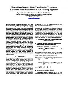
1. INTRODUCTION The research was done in Laboratory of Vehicle Suspension Dynamic in Faculty of Transport, Silesian University of Technology. The research of shock absorber built in vehicle was realized on laboratory test stand (fig. 1.) with vibration excitation (continuous of frequency regulation in 0-21 Hz range). This test stand was controlled by inverter.
Fig. 1. View and scheme of laboratory test stand where: 1. electric engine, 2. rotated mass, 3. crankshaft system, 4. moving platform, 5. hold down springs, 6. vertical slideway, 7. mount of platform Rys. 1. Widok i schemat stanowiska wymuszającego gdzie: 1. silnik napędowy, 2. masa wirująca, 3. układ korbowy, 4. płyta najazdowa, 5. sprężyny dociskowe, 6. pionowe kolumny prowadzące, 7. mocowanie płyty
Force process consisted of three phases: increase of frequency, vibration with constant frequency and decrease of frequency. The accelerations of platform, sprung and unsprung mass were recorded. The signals were recorded in digital form with 500 Hz sampling frequency. The scheme of measurement system is showed on fig. 2.
Acceleration sensor
Analog Digital
Computer with
ADXL
converter µDAQ
MatLab software
Fig. 2. Scheme of measurement system Rys. 2. Schemat toru pomiarowego
For acceleration measure were used the ADXL 204 and ADXL 321 sensors produced by Analog Devices. These are modern parametric sensors built in chip. Table 1 shows the parameters of these sensors.
Usage of Short Time Fourier Transform…
73 Table1
Measurement range Nonlinearity Sensitivity Frequency band Resonant frequency of sensor Temperature range Power supply
Parameters of ADXL sensors ADXL 204 +/- 1,7g 0.2 % FS 595mV/g 2,5 kHz 5,5 kHz -55 ... 125 oC 3-6 V
ADXL 321 +/- 18 g 0.2 % FS 57 mV/g 2,5 kHz 5,5 kHz -20 ... 70 oC 3-6 V
The acceleration sensors were mounted (fig. 3) on test platform, unsprung mass (on the arm near the wheel) and sprung mass (on the point of upper McPherson strut mount) of Fiat Seicento.
Fig. 3. Points of sensors mounted: A – on sprung mass, B – on unsprung mass Rys. 3. Miejsca mocowania przetworników A – na nadwoziu, B – na wahaczu
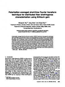
In Fiat Seicento was built front shock absorber with simulated fault (oil leak – the volume of oil was changed in the range 100% -50% with 10% step). The construction of this shock absorber was modified in order to make oil volume variable (fig. 4.)
Fig. 4. The shock absorber before and after modification Rys. 4. Amortyzator przed i po modyfikacji
2. METHOD OF ANALYSIS The digital signals of accelerations were analysed with MatLab software. For the analysis this no stationary signals (signals with changeable frequency) the Short Time Fourier Transform method were used. The result of this method is 3-dimensional spectrum presenting the behavior of signal amplitude in time and frequency domain.
74
Ł. Konieczny, R. Burdzik, B. Śleziak The Short Time Fourier Transform equation: +∞
S (b, f ) =
∫ x(t ) ⋅ e
− j 2πft
⋅ w(t − b)dt
(1)
−∞
where: (t-b)- window width. In STFT method, frequency analysis (FFT) is made for the following fragment of signal multiply by window function with constant width w(t-b)=const. The following fragments are analysed independently. The main disadvantage of this method is constant width of window (using narrow window in time domain we can get good time resolution but in the resolution in frequency domain will be worst). So the windows width is some kind of compromise between resolution in time and frequency domain). One way of improving the resolution in frequency domain for the single fragment of FFT analysis, is zero-complementing method. In this process to the original signal are added samples with zero value of amplitude to increase length of this signal (this method should be used carefully because the law of decreasing profits is valid here).The shape of the window is also very important. For rectangle window the jump changes at the beginning and at the end of windows are the source of leak in spectrum. For minimalizing of this effect can be used other windows decreasing the amplitude for the beginning and the end (for example triangle, Hanning, Hamming). The next way of improving the selectivity of STFT method is superposition of windows (each sample is used several times for single FFT process). In this research the acceleration of unsprung mass was analysed by STFT with the rectangle window with interval of time 0,5 s. Each fragment was 100% elongated by using complement zero method and analysed with FFT process. The windows were superpositioned in 50%. The example time realization of unsprung mass with each of the three phases of vibration excitation is showed on fig. 5.
Fig. 5. Example time realization of unsprung mass accelerations Rys. 5. Przykładowy przebieg czasowy przyśpieszeń drgań mas nieresorowanych
There was obtained STFT spectrum with 1 Hz resolution in frequency domain. In this spectrum the frequency band (fig. 6) with resonance frequency was isolated (middle frequency was 12 Hz, width of frequency band 3Hz).
Usage of Short Time Fourier Transform…
75
Rys. 6. The example of STFT spectrum with sign middle frequency 12 Hz Rys. 6. Przykładowe widmo STFT z zaznaczoną analizowaną częstotliwością f=12 Hz
Fig. 7 presents time section of STFT for chosen frequency band (11-13Hz) including the resonance frequency of unsprung mass. In this band the estimators W1 and W2 are mean of maximum amplitude in this band for phase increases frequency (W1) and phase decreases frequency (W2).
Fig. 7. Time section of STFT for chosen frequency band Rys. 7. Przekrój czasowy STFT dla analizowanego zakresu
76
Ł. Konieczny, R. Burdzik, B. Śleziak
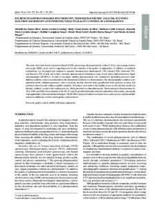
3. EXAMPLE RESULTS OF RESEARCHES The fig. 8 presents the STFT spectrum for new shock absorber (without oil leak)
Fig. 8. STFT spectrum for new shock absorber Rys. 8. Widmo STFT dla amortyzatora w stanie nominalnym
Fig. 9 presents the STFT spectrum for shock absorber with oil leak (60% volume of oil)
Fig. 9. STFT spectrum for shock absorber with oil leak (60% volume of oil) Rys. 9. Widmo STFT dla amortyzatora w stanie nominalnym z 60% napełnieniem olejem amortyzatorowym
Usage of Short Time Fourier Transform…
77
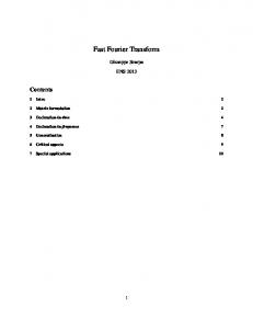
4. CONCLUSION Fig. 10 presents the value of estimators W1 and W2 for shock absorbers with different volume of oil.
Fig. 10. Juxtaposition in value of estimators W1 and W2 for shock absorbers with different volume of oil Rys. 10. Zestawienie wartości estymatorów W1 i W2 dla amortyzatora w różnym stanie napełnienia
The chosen estimators are sensitive to changes of oil volume in shock absorber. For small oil leak (volume of oil higher than 80%) the changes of W1 and W2 estimators are very small. For large oil leak (in case of oil volume below 80%) the amplitudes in chosen frequency band are increasing. These increases aren’t the same for both estimators. For phase increase frequency the increase of estimator W1 is monotonic function. For phase decreases frequency the values of W2 estimator are larger and similar (below 80%volume of oil). These results in the following researches where other methods of signal analysis will be used. References 1. Gardulski J.: Simulation studies of mechanical system with non-linear parameters of the structure for operating construction needs. Machine Dynamics Problems. Vol. 23 No 3, 1999. 2. Gardulski J.: Bezstanowiskowa metoda oceny stanu technicznego zawieszeń samochodów osobowych. Wydaw. Instytutu Technologii Eksploatacji, Radom, 2003. 3. Gardulski J., Warczek J.: Zastosowanie krótkoczasowej transformaty Fouriera w diagnostyce zawieszeń pojazdów samochodowych. Zeszyty Naukowe Pol. Śl., Seria Transport, z. 44, nr 1562, 2002, str. 23-29. 4. Gardulski J., Konieczny Ł, Burdzik R.: Wykorzystanie STFT w identyfikacji stanu technicznego amortyzatorów badanych metodą drgań swobodnych. Zeszyty Naukowe Pol. Śl., Seria Transport, z. 57, nr 1675, 2005, str. 107-114. 5. Gardulski J., Konieczny Ł., Burdzik R.: Diagnostyka stanu technicznego amortyzatora zabudowanego w pojeździe samochodowym z wykorzystaniem STFT. Diagnostyka maszyn roboczych i pojazdów. XII Konferencja naukowa, Bydgoszcz - Borówno, 23-25 czerwiec 2005. Warszawa: Polskie Towarzystwo Diagnostyki Technicznej, Diagnostyka. vol.33, 2005, s. 25-28, 6. Lyons R.: Wprowadzenie do cyfrowego przetwarzania sygnałów. WKiŁ, Warszawa, 1999. 7. Zieliński T.: Cyfrowe przetwarzanie sygnałów. Od teorii do zastosowań. WKiŁ, Warszawa, 2007.
Received 9.01.2008; accepted in revised form 2.07.2009