produce more efficient database schemas without loss of data integrity and ..... we have potentially higher retrieval cost (e.g., given the transaction âlist all.
INFORMATION
SCIENCES
55, 49-67
Usage Refinement for ER-to-Relation TOBY
(1991)
49
Design Transformations
J. TEOREY
Center for Information Technology Integration (CITI) and Department of Electrical Engineering and Computer Science, The UniL~ersityof Michigan, Ann Arbor, Michigan 48109-2122
DONGQING
YANG
Computer Science and Technology, Peking lJnil,ersity, Beijing, The People’s Republic of China
ABSTRACT
Database schema refinement based on usage is proposed as a useful next step in a practical database design methodology founded upon entity-relationship (ER) conceptual modeling and transformation to normalized relations. A simple cost model is defined and applied to several examples and a case study, illustrating the important trade-offs among query and update costs, storage requirements, and degree of normalization with its data integrity implications.
1.
INTRODUCTION
Database design techniques for network and hierarchical systems often make use of processing requirements to refine the conceptual (entity-relationship) or logical (DBMS-processible) schema before the physical design phase if there are obvious large efficiency gains to be made [l, 4, lo]. The justification for this approach is that once physical design begins, the logical schema is considered to be fixed and is thus a constraint on efficiency. The database designer would often like to remove this inflexibility if possible. A similar technique could be applied to relational databases if it would produce more efficient database schemas without loss of data integrity and would be relatively easy to implement. Our goal is to define a relational schema refinement algorithm based on a process-oriented or usage view that could increase the database efficiency for current processing requirements, and yet retain all the information content of the functional dependency or OElsevier Science Publishing 655 Avenue of the Americas,
Co., Inc. 1991 New York, NY 10010
0020-0255/91/$03.50
50
TOBY J. TEOREY AND DONGQING YANG
natural view of data. Thus the database would still be an accurate representation of real-world relationships and potentially more adaptable to future processing requirements. The application of a usage refinement algorithm is the logical next step in practical database design methodologies suggested by [3, 5, 111, starting with conceptual modeling [2], transforming from the ER to the relational model, and normalization. Usage refinement could be used to specify a!ternative logical structures to be considered during physical design, and thus provide the physical designers with more feasible solutions to choose from. More efficient databases are therefore likely to be defined. 2.
RELATION USAGE REFINEMENT
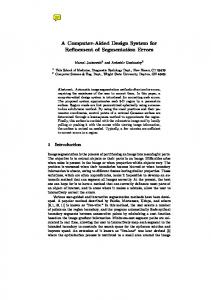
We assume that all attributes are initially assigned to relations based on functional dependencies, and that the relations are at least 3NF (normal forms) [7, 81. This establishes the requirement for an accurate representation of reality and for flexibility of the design for future processing requirements. Efficiency for the current query requirements should increase by redundantly adding attributes, used together in a query, to an existing relation so that all attributes needed for that query reside in a new relation, called a join relation. This is known as materializing the join [9]. Access time will now be greatly reduced because fewer joins will be needed. However, the side effects of this redundancy include an increase in storage space required, an increase in the update cost, potential denormalization and loss of integrity, and program transformations for all applications containing joins that are materialized. These effects require careful consideration. As an example of such an effect, let us assume that the relation PROJECT is associated with additional relations PART and SUPPLIER, as shown in Figure 1. We use query by example (QBE) to illustrate processes because of its extensive processing semantics [12]. The extension of the PART relation is shown as a means of reducing the number of joins required in the query. This extension results in a denormalization, with the side effects of add and update anomalies. However, the delete anomaly cannot occur because the original data are redundant in the extended schema. For example, SUPP-NO + SUPP-CITY in the extended PART relation (EXT-PART) is reproducible from PART-NO,PROJ-NAME -+ SUPP-NO in relation PART and SUPP-NO -+ SUPP-CITY in relation SUPPLIER. The storage and processing cost of a logical relational database is to be computed for both the existing and new join relations: COST=C,*(T,+T,)+C,*V,
(1)
ER-TO-RELATION
DESIGN
51
TRANSFORMATIONS
Original relations and process (query) PART(PART-NO,PROJ-NAME,SUPP-NO,PRICE) SUPPLIER(SUPP-NO,SUPP-CITY,SUPP-MGR) PROJECT(PROJ-NAME.HQ-CITY) Query: For a given project, display the supplier numbers, supplier cities, and project headquarters city.
PART-NO,PROJ-NAME --> SUPP-NO 1PRICE SUPP-NO --> SUPP-CITY 1SUPP-MGR PROJ-NAME --> HQ-CITY QBE representation of the query
IPROJNAMF I l-
PART IPART-NO
I SUPPLIER
ISUPP-NO IPELGE I I p.x I I
]m
I
SUPP MGR
I
x-
PROJECT IPROJ I l-
-
I I
IHQ-CITYI 1P.Z I
Extended relation PART in 1 NF EXT-PART (PART NO.PROJ NAMF.SUPP-NO,SUPP-CITY,HC?-CITY,PRICE) SUPPLIER &SUPP-CITY,SUPP-MGR) PROJECT (PROJ-NAMF,HQ-CITY)
Fig. 1. Relation extension causing denonnalization.
where C, = unit cost per second for query or update processes C, = unit cost per byte for stored data Tq = I/O
service time for query processes (seconds)
T, = I/O
service time for update processes (seconds)
V, = total volume in bytes for stored data Unit costs are selected on the basis of the computing environment defined in the requirements specification. I/O service time for query and update can
TOBY J. TEOREY AND DONGQING YANG
52
be determined from the processing operations, their frequencies, and the hardware device characteristics given, while stored data volume can be obtained from the size of the relations defined 14, lo]. Each query process must be expressed in terms of basic relational algebra operations such as selection, projection, and join. Some initial assumptions are made about sequential and random accesses needed to efficiently accomplish the query or update at this point, but detailed use of indexes, sorting, and so forth are deferred to physical design when the final configuration decisions are made.
2.1.
RELATION
USAGE ALGORITHM
The relation usage strategy is to select only the most dominant processes to determine modifications to relations that will most likely improve performance. The basic modification is to add attributes to existing relations in order to reduce join operations. 1. Select the dominant processes on the basis of criteria such as high frequency of execution, high volume of data accessed, response time constraints, or explicit high priority. As a rule of thumb any process with at least a factor of 10 higher frequency of execution or data volume accessed than another process is considered to be dominant. 2. Define join relations, when appropriate, to materialize joins for dominant processes. 3. Evaluate total cost for storage, query, and update for the database schema, with and without the extended relation, and determine which configuration minimizes total cost. 4. Consider also the possibility of denormalization due to a join relation and its side effects. If a join relation schema appears to have lower storage and processing cost and insignificant side effects, then consider that schema for physical design in addition to the original candidate relation schema. Otherwise, consider only the original schema. In general, joins based on nonkeys should be avoided. They are likely to produce very Iarge relations, thus greatly increasing storage and update cost. For example, if two relations have 100 and 200 tuples, respectively, then a join based on the key of either one will result in a maximum of 200 tuples, but a join based on a nonkey of either one could result in a maximum of 100X200 or 20,000 tuples. Null values are also to be restricted to nonkey attributes so that they will not be inadvertently used in join operations.
ER-TO-RELATION
DESIGN
TRANSFORMATIONS
53
PART-OF
BELONGS-TO
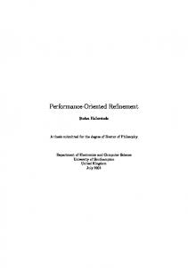
Fig. 2.
Company personnel and project database (extended ER diagram).
2.2. ALGORITHM
APPLICABILITY
The following examples, extending the company personnel and project database design problem defined in [ll] and illustrated in Figure 2, show the extremes of applicability and nonapplicability of the relation usage algorithm. In each case we apply the algorithm to a given relational schema and given processing requirements. Cost trade-offs are then evaluated to determine if schema refinement is justifiable. The ER conceptual model of the company personnel and project database includes extensions of the ER model such as generalization, i.e. the concept of category (EMPLOYEE) and subcategory (MANAGER, ENGINEER, TECHNICIAN, SECRETARY), where subcategory names are based on values of the EMPLOYEE attribute JOB-TITLE. Optional membership (or existence) of an entity in a relationship is designated by a 0 on the arc between that entity and the relationship. Otherwise the membership is assumed to be mandatory.
TOBY J. TEOREY
54
AND DONGQING
YANG
Note that the extended ER constructs also contain ternary relationships, which are defined by the shading of the corners of the triangles that connect the entities involved in the relationship. The shading indicates the functional dependencies (FDs) associated with the relationship. All FDs are defined by the primary keys of the three entities in the relationship, and an unshaded corner of the triangle implies that the primary key of that entity is on the right-hand side of an FD, and the primary keys of the other two entities are the composite determinant of the FD. Thus, the number of unshaded corners equals the number of FDs associated with the relationship. When all three corners are shaded, there are no FDs, and the key of the relationship is the composite of all three primary keys of the involved entities. Applying the methodology suggested in [ill and summarized in Appendix I, the final normalized relations are the following: 1. DlVlSlON(DIV-NO,HEAD-EMP-NO,
. . .)
2. DEPARTMENT(DEPT-NO,DEPT-NAME,ROOM-NO,
...
DIV-NO,MANAG-EMP-NO) 3. EMPLOYEE(EMP-NO,EMP-NAME,JOB-TITLE,
. ..,
DEPT-NO,SPOUSE-EMP-NO,PC-NO) 4. SKILLtSKILL-NO, . . .) 5. PROJECTtPROJ-NAME, . . .) 6. LOCATION(LOC-NAME,
. . .)
7. EMP.MANAGER(EMP-NO, 8. EMP.ENGINEER(EMP-NO,. 9. EMP.TECHNICIAN(EMP-NO,
. . .) . .) . . .)
10. EMP.SECRETARY (EMP-NO, . . .) 11. PC(PC-NO, . . .) 12. PRF-ASSOCfPA-NO, . . .) 13. BELONGS-TO(PA-NO ,EMP-NO) 14. SKILL-USED(EMP-NO,SKILL-NO,PROJ-NAME) 15. ASSIGNED-TO(EMP-NO,LOC-NAME,PROJ-NAME) 16. ROOM(ROOM-NO,PHONE-NO) 2.2.1. Example I Example 1 illustrates the most favorable ment with the relation usage algorithm (see pair of employee and project in which the where the employee lives” is executed
conditions for efficiency improveFigure 3). The query “display each project is located in the same city by a join of EMPLOYEE and
ER-TO-RELATION
DESIGN TRANSFORMATIONS
55
Relations
Bytee/tuple
Tuples
Total Bytes
EMPLOYEE(EMP-NO,EMP-CITY,..) PROJECT(PROJ-NAME,HO-CITY,..) ABBIGNEO-TO(EMP-NO.PRQ,j&Q&..)
120 200 20
10000
1200 KB 100 KB 400 KB
500 20000
Query: Oispiay each pair of employee and project in which the project headqua~ers(HQ) is located in the same city where the employee lives. Update: Delete a given employee from all associated projects. QBE representation of the query -=EIEMNQ
I I
I-
1p.x
I
z
fitly I
P.Y
IHO-GITYI / z /
ASSIGNED-TO I
EMP_NO[ eB(;blNAMP I 1x1; I
QBE representation of the update ASSIGNED-TO 1 EFAP_NO I ~ 0.1 * I
X
1 I
PROJECT1 PR~-~ I X
I HO-CITY 1 I
I
Unit costs: C@p = 9.00 per disk-hour, CQs = .0031 per page-day Frequency of all processes: 1OO/day Fig. 3.
Example 1 relations and processes.
ASSIGNED-TO over EMP-NO, followed by 20,000 random accesses to PROJECT (based on PROJ-NAME) to match HQ-CITY with each EMP-CITY in the temporary relation resulting from the join. To simplify the computation of query time the relations are assumed to be accessed as: EMPLOYEE(sequential, ordered on EMP-NO), PROJECT (indexed on PROJ-NAME}, and ASSIGNED-TO (sequential, ordered on EMP-NO). Using the hardware configuration for the Amdahl5860 system (currently an IBM 3090-6001 at the University of Michigan, the following timing characteristics occur: Page transfer time (at 4,096 bytes per page): 3.4 ms Average disk rotation time (half rotation): 8.3 ms Average disk seek time: 16.0 ms Average sequential page access = 11.7 ms Average random page access = 27.7 ms CP = 9.00 dollars per I/O hour C, = .0031 dollars per page-day Given the number of bytes in each of the relations and the searching required for the query, we can calculate the I/O service time CT,) for the query, and
TOBY J. TEOREY
56
AND DONGQING
YANG
thus the total cost (Equation 1). The remainder of the example is to determine the number of pages for query and update operations and storage space and to calculate total cost. rq = scan EMPLOYEE + scan ASSIGNED-TO + 20,000 random accesses to PROJECT = ceiling(l,200,000/4,096)* 11.7 + ceiling(400,000/4,096)*ll.7 + 20,000*27.7 ms = 558.575 set = .155 hour I/O
cost (query) = C,*T, = 9.00*.155 = 1.396
I/O
cost (at 100 queries per day) = 139.6
The update operation “delete a given employee from all associated projects” requires a random access to ASSIGNED-TO based on EMP-NO and a scan of an additional page to delete all tuples with a given EMP-NO. T, = 27.7 ms + 11.7 ms = .039 seconds I/O
cost (update)
= C,* T, = 9.00*.039/3,600 = .OOOl
I/O cost (at 100 updates per day) = .Ol Storage cost = C,* V, = .0031 per page day* [ceiling(l,200,000/4,096) + ceiling( 100,000/4,096) + ceiling(400,000/4,096)] = .0031*416 pages = 1.29 Total cost = 139.6 + .Ol+ 1.29 = 140.9 The extended join relation solution is to append to ASSIGNED-TO the attributes EMP-CITY and HQ-CITY so that only a single scan of the new relation, which we will call EXT-ASSIGNED-TO, is needed to satisfy the query.
ER-TO-RELATION
DESIGN
57
TRANSFORMATIONS TABLE 1
Summary of Total Cost Per Day (Examples 1 and 2) Join relation
Original relation 139.6 .Ol 1.29 140.9
1.4 2.9 1.5 5.8
57 .01
1.59 2.17
1.8 3.6
1.9 7.3
Query cost Update cost Storage cost Total cost
Query cost
Update cost Storage cost Total cost
EXT-ASSIGNED-TO now has 40 bytes per tuple; therefore at 20,000 tuples it has a total of 800,000 bytes and is double the size of ASSIGNED-TO. Redoing the calculations for query, update, and storage with EXT-ASSIGNED-TO, we obtain the cost figures shown in Table 1. We see that there is a dramatic reduction in cost by using the extended join relation and avoiding the join and random indexing of the original solution.
2.2.2. Example 2 Example 2 illustrates the least favorable conditions for efficiency improvement with the reIation usage aIgorithm. The query given in Figure 4 is executed by a join on the relations EMPLOYEE and DEPARTMENT over the common attribute DEPT-NO. This is accomplished by a scan of EMPLOYEE and DEPARTMENT. DEPARTMENT and EMPLOYEE are assumed to be accessed sequentially based on DEPT-NO.
Tq = scan of EMPLOYEE + scan of DEPARTMENT = ceiling(2,000,OO0/4,096)* 11.7 ms +ceiling(15,000/4,0961* 11.7 ms = 5,713 ms + 47 ms = 5,760 ms I/O cost (query)
I/O
= 9.00*5.76 set/3,600 = ,014
cost (query at frequency
of 100 per day) = 1.4
58
TQBY J. TEQREY AND DGNGQXNG YANG
Relations
Bytesituple
Tuples
Total Bytes
200 250
10000 60
2000 KB 15KB
EMP IEMP_Nn.EMP-NAME,AUTQNPE,DEPT-NO) DEPT~~F~T-~,D~PT-NA~~,Q~F-~,E~P-NU~
Query: Display employee number, name, office, and department name for all employees with a given automobile type. Update: Scan the empfoyee relation and make necessary changes as specified in an in-Gore update f&t.
QBEreQresentationof the query EMPLOYEE 1HP-NO 1 P.A DEPAR~~~
1FMP NAME. 1AUT~~P~ d.6 1
1
l
1PEPT-NQ
[
X
1DFPT-NQ [ DEPT NAME 1QFF-NQ 1EMP_NO f x 1 FJ:c 1p.D I
QBE reprssentstion of the updete EMPLOYEE IEMeNo tJ.1 l
IEMP-NAME ; AU?-TYPF I *
Frequency of alf proc%sses:1Oolday Fig. 4.
Example 2 relations and processes.
The update of department number of every employee is accomplished with a scan (read) and rewrite of EMPLOYEE: T, = scan and rewrite of EMPLOYEE = [cei1ing(2,000,000/4,096~* 11.7 msJ”2
= 11,443 ms f/O cost (update) = 9.00”11.443 set/3,600 = .O29 I/O cost (update at frequency of 100 per day) = 2.9 Storage cost = ceiIing(Z,~O,~~4,096)*.0031 = 1.5 per day
+ceiIing(15,000/4,096)‘.0031
The extended join relation solution is to add the attributes ~~PT-~AM~ and OFF-NO to relation EMPLOYEE, thus increasing the tupfe size from 200 to 250 bytes. The size of the entire relation EXT-EMPLOYEE is 2.5 MB, compared to 2 MB for EMPLOYEE. The cost for query, update, and storage space for the extended relation is shown in Table 1. The results show higher cost in alI three areas that is due to the extended join relation, mainly because the relation EMPLOYEE is much larger than the relation ~EFA~T~ENT and the extension EXT-EMPLOYEE is larger than EMPLOYEE and DEPARTMENT
ER-TO-RELATION
DESIGN
TRANSFORMATIONS
59
combined. Thus, the join relation schema is not a candidate for physical design in this case. To summarize, the extended join relation tends to significantly lower the storage and processing cost for one or more joins if the joined relations are of comparable size, if only the smaller relation is extended, or if it can avoid a large number of random accesses to ai least one of the relations. 3.
A CASE STUDY
The following case study illustrates how the usage refinement approach easily extends a logical design methodology for simple improvements in performance. The problem definition is followed by the solution steps of ER model definition, functional dependency definition, transformation to relations, normalization and reduction of relations, and usage refinement. Tradeoffs among the degree of normalization, storage requirement, and query and update costs are analyzed before the final relation definitions can be specified. 3.1.
REQUIREMENT
SPECIFICATION
The management of a large retail store would like a database to keep track of their sales activities. The requirement for this database specifies six entities and their unique identifiers as follows: Entity CUSTOMER JOB ORDER SALESPERSON DEPARTMENT ITEM
Entity identifier CUST-NO JOB-TITLE ORDER-NO SALES-NAME DEPT-NO ITEM-NO
The following assertions
Identifier
length
6 char 24 char 9 char 20 char 2 char 6 char
Cardinality 80,000 80 200,000 150 10 5,000
describe the data relationships:
1. Each customer has one job title, but different customers may have the same job title. 2. Each customer may place many orders, but only one customer may place a particular order. 3. Each department has many salespersons, but each salesperson must work in one department. 4. Each department has many items for sale, but each item is sold in only one department (“item” means item type, like IBM PC). 5. Each order could be placed for several different items located in the same or different departments.
TOBY J. TEOREY
60
AND DONGQING
YANG
6. For each order, items ordered in different departments must involve different salespersons, but all items ordered within one department must be handled by exactly one salesperson. In other words, for each order, each item has exactly one salesperson; and for each order, each department has exactly one salesperson. 3.2.
DESIGN PROBLEM
1. Using the information given above, and in particular the six assertions, derive an ER diagram and a set of functional dependencies (FDs) that represent all the data relationships. 2. Transform the ER diagram into a set of candidate relations. List the relations, their primary keys, and other attributes. 3. Find the minimum set of BCNF relations that are functionally equivalent to the candidate relations. Analyze performance and integrity trade-offs that result from the definition of this minimum set. 4. Given the transactions “select all order numbers assigned to customers who are computer engineers” and “add a new customer and the customer’s order to the database,” analyze the performance and data integrity trade-offs for strategies to execute these transactions with the minimum-set BCNF schema and a refined schema designed to reduce the number of joins needed for data retrieval. 3.3.
LOGICAL DESIGN
Our first step is to develop an ER diagram (Figure 5) and a set of FDs to correspond to each of the six assertions given. Normally the ER diagram is developed without knowledge of all the FDs, but in this example the nonkey attributes are omitted so that the entire database can be represented with only a few statements and FDs. The result of this analysis, relative to each of the six assertions given above, is as follows: ER construct
Functional
dependencies
CUSTOMER(many:JOB(one) 2. ORDER(many):CUST-NOcone) 3. SALESPERSON(many):
CUST-NO + JOB-TITLE ORDER-NO + CUST-NO SALES-NAME + DEPT-NO
DEPARTMENTcone) 4. ITEM(many):DEPARTMENT(one) 5. No meaningful relationship 6a. ORDER(many):ITEM(many): SALESPERSON(one) 6b. ORDER(many): DEPARTMENT(many): SALESPERSON(one)
ITEM-NO + DEPT-NO NONE ORDER-NO,ITEM-NO -+ SALES-NAME ORDER-NO,DEPT-NO -+ SALES-NAME
1.
ER-TO-RELATION
DESIGN
61
TRANSFORMATIONS
CUSTOMER
b
JOB
I
ORDER
SALESPERSON
1 DEPARTMENT Fig. 5.
Extended
ER diagram
v for the retail store database.
The candidate relations needed to represent the semantics of this problem can be easily derived from the constructs for entities and relationships. Primary keys are underlined. 1. 2. 3. 4. 5. 6. 7. 8.
CUSTOMER(CUST-NO,JOB-TITLE) JOB(JOB-TITF ORDER(oRDER-NO,CUST-NO) SALESPERSON(SALES-NAME,DEPT-NO) DEPARTMENT(DEPT-NO) ITEM(ITEM-NO,DEPT-NO) ORDER-ITEM-SALES(ORDER-NO,ITEM-NO,SALES-NAME) ORDER-DEPT-SALES(ORDER-NO,DEPT-NO,SALES-NAME)
Candidate relations l-6 are formed directly from entities and are all BCNF. Relation 7 is also BCNF, but relation 8 is only 3NF. Relation 8 has two functional dependencies: ORDER-NO,DEPT-NO + SALES-NAME SALES-NAME + DEPT-NO which cannot be decomposed into independent BCNF relations if the first functional dependency is still to be preserved. Consequently it must remain in 3NF [3]. This process of decomposition and reduction of relations moves us closer to a minimum set of 3NF or BCNF relations. Additionally, we must consider the relations JOB and DEPARTMENT. Because we have not defined other at-
62
TOBY J. TEOREY AND DONGQING YANG
tributes in these relations, JOB and DEPARTMENT are simple relations consisting of a single key attribute. When this occurs, and the key attribute appears in the other relation as a nonkey, we can consider the elimination of the simple relation. The trade-off is between the decrease in storage space and update cost when we eliminate a relation, and the possible loss of data integrity as a side effect of deletions on another relation in which the key of the eliminated relation has become a nonkey. In our example, if we can justify this trade-off and eliminate the simple relations, we have the following minimum set of 3NF and BCNF relations: 1. 2. 3. 4.
CUSTOMER( GUST-NO, JOB-TITLE)
BCNF
ORDER{ ORDER-NO, CUST-NO)
BCNF
SALESPERSON( SALES-NAME,
DEPT-NO)
ITEM( ITEM-NO, DEPT-NO)
5. ORDER-ITEM-SALES( ORDER-NO,ITEM-NO, SALES-NAME) 6. ORDER-DEPT-SALES( ORDER-NO,DEPT-NO, SALES-NAME)
BCNF BCNF BCNF 3NF
In summ~, the reductions shown above have decreased storage space and update cost and have maintained the normalization at a minimum of 3NF, but we have potentially higher retrieval cost (e.g., given the transaction “list all job-titles”) and have increased the potential for loss of integrity due to the elimination of simple relations with only key attributes.
Let us now look at the quantitative trade-offs of further refinement of relations to accommodate processing efficiency. We shall assume that each of the following transactions are to be executed once per fixed time unit: 1. Query, Select all order numbers assigned to customers who are computer engineers. 2. Update, Add a new customer and the customer’s order to the database. Using the minimum-it 3NF/BCNF schema, we can execute the transactions in a number of different ways. Let us first assume that the relations are all ordered physically by their primary keys. We use the following strategy for the first transaction: Sort the ORDER relation by CUST-NO, then join relations ORDER and CUSTOMER with a single scan of each, and select only tuples that have JOB-TITLE of computer engineer. We then project on
ER-TO-RELATION
DESIGN
TRANSFORMATIONS
63
ORDER-NO for the resulting display. To simplify the analysis we assume that a sort of n tuples takes n log, n tuple accesses (TA) and that computer engineers make up 5% of the customers and orders in the database. TA = sort ORDER + scan ORDER + scan CUSTOMER + create ORDER-CUST + scan ORDER-CUST + create COMP-ENGR + project COMP-ENGR = (200,00010g2200,000)
+200,000+80,000+200,000
+ 200,000 + 200,000* .05 + 200,000* .05 = 200,000*(17.61+3.10)
+80,000
= 4,222,OOOtuple accesses Since all tuple accesses are sequential in this strategy, and assuming 10 ms per sequential block access and block size of 1000 bytes, we estimate the I/O service time to process this by first computing the blocking factors for relations ORDER, CUSTOMER, ORDER-CUST and COMP-ENGR: 66, 33, 25, and 25, respectively. We compute the physical block accesses (PBA) as follows: PBA = cei1ing(200,000*18.61/66) = 75,619 IOTIME
+ ceiling(80,000/33)
+ ceiling(420,000/25)
= 75,619*10 ms = 756 seconds
The strategy to execute the second transaction using the same schema is to scan each relation (ORDER and CUSTOMER) and rewrite both relations with the new order. PBA = ceiling(200,000/66)*2 = 10,912 IOTIME
+ ceiling(80,000/33)*2
= 10,912* 10 ms = 109 seconds
If we refine the minimum-set 3NF/BCNF schema to avoid the join in the first transaction, the resulting schema will have a single relation ORDER-CUST (ORDER-NO,CUST-NO,JOB-TITLE) instead of separate relations ORDER and CUSTOMER. This avoids not only the join, but also the sort needed to get
TOBY J. TEOREY
64
AND DONGQING
YANG
both relations ordered by CUST-NO. The strategy for the first transaction is now to scan ORDER-CUST once to find the computer engineers, write out the data to disk, and then read back from disk to project the resulting temporary relation COMP-ENGR for the final display. PBA = ceiling(200,000/25) =
IOTIME
f [Ceiling(200,ooo’.o5/25)1*2
8,800 = 8,800*10 ms = 88 seconds
The strategy for the second transaction using this refined schema is to scan ORDER-CUST once to find the point of insertion, and then to scan again to reorder the relation. PBA = ceiling(200,000/25)*2 = 16,000 IOTIME
= 16,000* 10 ms = 160 seconds
Common to the two strategies is the addition of an ORDER tuple to the relations ORDER-ITEM-SALES and ORDER-DEPT-SALES. For the sake of simplicity we will assume these relations to be unsorted, so the addition of a new order will require only one tuple access at the end of the relation, and thus negligible IOTIME. The basic performance and normalization data for these two schemas and the two transactions given above are summarized in Table 2. The refined schema dramatically reduces the I/O time for the query transaction; but the cost is the loss of performance for the update, more storage space, and significant reduction in the degree of normalization. The
TABLE
2
Comparison of Performance and Integrity of Original Relations Minimum set 3NF/BCNF schema (ORDER and CUSTOMER) Query Update Storage space Normalization
756 seconds 109 seconds 5.4 MB 3NF
and Join Relation
Refined schema (ORDER-CUST) 88 seconds 160 seconds 7.8 MB (relevant 2NF
relations)
ER-TO-RELATION
DESIGN
6.5
TRANSFORMATIONS TABLE 3
Comparison of Three Schemas for Performance and Integrity ORDER-CUSTOMER Query Update Storage space INormalization
756 seconds 109 seconds 5.4 MB 3NF
ORDER-CUST
All 3 relations
88 seconds 160 seconds 7.8 MB 2NF
88 seconds 269 seconds 13.2 MB (relevant relations) 2 NF, 3NF combination
normalization is reduced because we now have a transitive functional dependency ORDER-NO + CUST-NO --) JOB-TITLE in relation ORRER-CUST. The implication of this is, of course, the delete anomaly for JOB-TITLE when a customer deletes an order or the order is filled. We can illustrate the trade-off between degree of normalization and performance with a simple alternative schema. In this case, instead of replacing ORDER and CUSTOMER by ORDER-CUST, we keep all three relations in the database. Thus normalization for these relations is preserved from the original schema. The cost is not only for increased storage space and update I/O time, but also for a greater choice of retrieval options requiring more query optimization software. The performance changes are summarized in Table 3.
4.
CONCLUSION
A practical approach to extending a logical database design methodology for database usage has been presented and illustrated with several detailed examples, extending previous work based upon requirements analysis using the ER model and its transformation to the relational model. The extensions focus on the trade-offs between normalization, minimization of the number of relations, and the relation refinements to improve query processing at the expense of update and storage cost. The degree of normalization provides a well-defined level of data integrity in terms of the delete anomaly. The significance of these performance and data integrity differences depends upon the global set of objectives and computing environment for the database, and must be analyzed in that context. For instance, the performance differences must be evaluated for all relevant transactions, present and projected. Storage space differences may or may not be significant in the computing environment. Deletion integrity problems need to be evaluated on a case-by-case basis to determine whether the side effects of certain tuple deletions are destructive to the objectives of the database. In summary, the database designer now has the ability to evaluate the trade-offs among query,
66
TOBY J. TEOREY AND DONGQING YANG
update, storage space, and integrity associated with normalization. This knowledge can be applied to a variety of database design problems.
APPENDIX I .WMMARY
OF LOGICAL
RELATIONAL
1. Extended ER (EER) modeling 1.1 Identify entities and attach 1.2 Identify generalization and 1.3 Define relationships. 1.4 Integrate multiple views of
DATABASE
DESIGN
STEPS
of requirements attributes to each. subset hierarchies. entities, attributes, and relationships.
2. Transformation of the EER model to relations 2.1 Transform every entity into one relation with the key and nonkey attributes of the entity. 2.2 Transform every many-to-many binary (or unary) relationship into a relationship relation. 2.3 Transform every ternary (or higher n-ary) relationship into a relationship relation. 3. Normalization of relations 3.1 Derive the primary FDs from the EER diagram. 3.2 Examine all the candidate relations for MVDs and secondary FDs. 3.3 Normalize all candidate relations to the highest degree desired, eliminating any redundancies that occur in the normalized relations. 4. Usage refinement (logical/physical design boundary) 4.1 Select dominant processes. 4.2 Define join relations. 4.3 Evaluate total cost for storage, query, and update. 4.4 Consider the possible effects of denormalization.
REFERENCES 1. P. Bertaina, A. Dileva, and P. Giolito, Logical design in CODASYL and refational environments, in Methodology and Tools for Dura Base Design 6. Ceri, ed.), North-Holland, Amsterdam, 1983, pp. 85-117. 2. P. P. Chen, The entity-relationship model-Toward a unified view of data, ACM Trans. Database Sysrem 1(1):9-36 (March 1976). 3. C. J. Date, An Introduction to Database Systems, Vol. 1 (4th ed.), Addison-Wesley, Reading, MA, 1986.
ER-TO-RELATION
DESIGN TRANSFORMATIONS
67
4. I. Hawryszkiewycz, Database Analysis and Design, SRA, Chicago, 1984. 5. D. Howe, Data Analysis and Data Base Design, Arnold, London, 1983. 6. W. H. Inmon, Optimizing performance with denormalization, Database Programming and Design 1(1):34-39 (December 1987). 7. W. Kent, A simple guide to five normal forms in relational database theory, Comm. ACM 26(2):120-125 (February 1983). 8. D. Maier, Theory of Relational Databases, Computer Science Press, Rockville, MD, 1983. 9. M. Schkolnick and P. Sorenson, DENORMALIZATION: A performance oriented database design technique, in Proceedings of the AICA 1980 Congress, Bologna, Italy, AICA, Brussels, 1980, pp. 363-377. 10. T. Teorey and J. Fry, Design of Database Structures, Prentice-Hall, Englewood Cliffs, NJ, 1982. 11. T. J. Teorey, D. Yang, and J. P. Fry, A logical design methodology for relational databases using the extended entity-relationship model, ACM Computing Surwys 18(2):197-222 (June 1986). 12. M. M. Zloof, Query by example, Proc. Natl. Computer Conf., Vol. 44, AFIPS Press, 1975, pp. 431-438. Receiued 16 March 1988; accepted 30 September 198X