No. 18. Use of Component-Based Software Architectures in Industrial. Control
Systems. Frank Lüders. 2003. Department of Computer Science and Engineering
.
Mälardalen University Licentiate Thesis No. 18
Use of Component-Based Software Architectures in Industrial Control Systems
Frank Lüders 2003
Department of Computer Science and Engineering Mälardalen University
Copyright © Frank Lüders, 2003 ISBN number: 91-88834-19-0 Printed by Arkitektkopia, Västerås, Sweden Distribution: Mälardalen University Press
Table of Contents Abstract ....................................................................................................................................................iii Acknowledgements .................................................................................................................................. v Publications Included in this Thesis.........................................................................................................vii Other Related Publications.......................................................................................................................ix 1
2
Introduction ........................................................................................................................................ 1 1.1
Research Questions................................................................................................................... 3
1.2
Research Methods ..................................................................................................................... 6
1.3
Contributions.............................................................................................................................. 9
Background...................................................................................................................................... 13 2.1
2.1.1
Definitions of Software Architecture.................................................................................. 13
2.1.2
Architectural Design.......................................................................................................... 16
2.1.3
Evaluation of Software Architectures ................................................................................ 21
2.1.4
Architectural Description and Documentation ................................................................... 24
2.2
Component-Based Software Engineering ................................................................................ 31
2.2.1
Definitions of Software Components................................................................................. 31
2.2.2
Software Component Models and Technologies .............................................................. 34
2.2.3
Component-Based Software Engineering Practices ......................................................... 40
2.3
3
Software Architecture............................................................................................................... 13
Industrial Control Systems ....................................................................................................... 44
2.3.1
Levels of Industrial Control Systems................................................................................. 44
2.3.2
Programmable Controllers ................................................................................................ 50
Paper A: Specification of Software Components ............................................................................. 61 3.1
Introduction .............................................................................................................................. 61
3.2
Current Component Specification Techniques ......................................................................... 63
3.3
Specifying the Semantics of Components................................................................................ 68
3.4
Specifying Extra-Functional Properties of Components ........................................................... 78
3.5
Summary.................................................................................................................................. 81
3.6
Corrections to the Original Version .......................................................................................... 82
i
ii
Use of Component-Based Software Architectures in Industrial Control Systems
4
Paper B: Componentization of an Industrial Control System ........................................................... 83
5
6
7
4.1
Introduction .............................................................................................................................. 84
4.2
The ABB control system........................................................................................................... 85
4.3
Componentization .................................................................................................................... 88
4.3.1
Current software architecture............................................................................................ 88
4.3.2
Component-based software architecture .......................................................................... 91
4.3.3
Quality attribute analysis................................................................................................... 99
4.4
Lessons learned..................................................................................................................... 101
4.5
Related work .......................................................................................................................... 103
4.6
Conclusions and future work.................................................................................................. 104
4.7
Acknowledgements ................................................................................................................ 105
Paper C: Adopting a Software Component Model in Real-Time Systems Development................ 107 5.1
Introduction ............................................................................................................................ 107
5.2
Motivation............................................................................................................................... 109
5.3
Adopting Microsoft Models..................................................................................................... 110
5.3.1
COM Interfaces............................................................................................................... 111
5.3.2
Instantiation and Dynamic Linking .................................................................................. 113
5.3.3
Location Transparency with DCOM ................................................................................ 115
5.3.4
The Next Generation: .NET ............................................................................................ 117
5.4
Related work .......................................................................................................................... 118
5.5
Conclusion ............................................................................................................................. 118
Conclusion and Future Work.......................................................................................................... 121 6.1
Experiences from Industry...................................................................................................... 121
6.2
Analysis of Results................................................................................................................. 123
6.3
Outline of Future Work ........................................................................................................... 124
References..................................................................................................................................... 127
Abstract Component-based software engineering (CBSE) denotes the disciplined practice of building software from pre-existing smaller products, generally called software components, in particular when this is done using standard or de-facto standard component models. The popularity of such models has increased greatly in the last decade, particularly in the development of desktop and server-side software. The main expected benefits of CBSE are increased productivity and timeliness of software development projects. The last decade has also seen an unprecedented interest in the topic of software architecture in the research community as well as among software practitioners. CBSE has notable implications on a system’s architecture, and an architecture that supports CBSE, e.g. by mandating the use of a component model, is called a componentbased software architecture. This thesis investigates the benefits and problems related to the use of such architectures in industrial control systems, which are computer-based systems that control physical processes and equipment. The investigation is mainly performed through an industrial cases study of a global company developing a new generation of control systems, intended to replace several existing systems. To leverage its global development resources and the competency of different development centers, the company decided to adopt a componentbased software architecture that allows certain functionality to be realized by independently developed components. The architecture incorporates a limited version of a standard component model.
iii
iv
Use of Component-Based Software Architectures in Industrial Control Systems
The process of redesigning the software architecture is presented in this thesis, along with the experiences made during and after the project. An analysis of these experiences shows that the component-based architecture effectively supports distributed development and that the effort required for implementing certain functionality has been substantially reduced. The use of the selected component model in real-time systems is furthermore analyzed from a more general perspective. It is shown that adopting the model means that real-time requirements can still be satisfied in most cases, but that this may require certain precautions to be taken.
Acknowledgements I would like to thank my supervisor Ivica Crnkovic for all his help and support during my work with this thesis, and I am grateful to him and Erik Gyllenswärd, formerly of ABB, for giving me this opportunity in the first place. The research described in this thesis was made possible by grants from ABB and the Swedish KK Foundation. I greatly appreciate the helpful cooperation of project members at ABB in Malmö and Västerås, and I would particularly like to thank Staffan Andersson for his valuable input. Thanks also to Per Runeson and Björn Lisper who provided useful comments on the draft version of the thesis. I thank all the people currently and formerly at the Department of Computer Science and Engineering for providing a great social and professional environment, in particular Magnus Larsson and Andreas Sjögren who I have enjoyed working and laughing with. Finally, I wish to thank all my family and friends, and most specially Elise, for being there for me. I ask their forgiveness for ignoring them at times while burying myself in work.
v
Publications Included in this Thesis Paper A
Frank Lüders, Kung-Kiu Lau, and Shui-Ming Ho, “Specification of Software Components”, In Ivica Crnkovic and Magnus Larsson (Editors), Building Reliable Component-Based Software Systems, ISBN 1-58053-327-2, Artech House Books, 2000.
Paper B
Frank Lüders, Ivica Crnkovic, and Andreas Sjögren, “Case Study: Componentization of an Industrial Control System”, In Proceedings of the 26th Annual International Computer Software and Applications Conference – COMPSAC 2002, Oxford, England, August 2002.
Paper C
Frank Lüders, “Adopting a Software Component Model in RealTime Systems Development”, To appear in Proceedings of the 28th Annual IEEE/NASA Software Engineering Workshop, Greenbelt, Maryland, December 2003.
vii
Other Related Publications Frank Lüders, Ivica Crnkovic, and Andreas Sjögren, “A Component-Based Software Architecture for Industrial Control”, In Proceedings of the Third Working IEEE/IFIP Conference on Software Architecture – WICSA 3, Montreal, Canada, August 2002. Ivica Crnkovic, Magnus Larsson, and Frank Lüders, “Implementation of a Software Engineering Course for Computer Science Students”, In Proceedings of the 7th Asia-Pacific Software Engineering Conference – APSEC 2000, Singapore, December 2000. Ivica Crnkovic, Magnus Larsson, and Frank Lüders, “Software Process Measurements using Software Configuration Management”, In Proceedings of the 11th European Software Control and Metrics Conference, Munich, Germany, May 2000. Ivica Crnkovic, Magnus Larsson, and Frank Lüders, “The Different Aspects of Component Based Software Engineering”, In Proceedings of the Microprocessor Systems, Process Control and Information Systems Conference – MIPRO 2000, Opatija, Croatia, May 2000. Ivica Crnkovic, Magnus Larsson, and Frank Lüders, “State of the Practice: Component-based Software Engineering Course”, In Proceedings of the Third International Workshop on Component-Based Software Engineering, Limerick, Ireland, January 2000.
ix
1 Introduction Component-based software engineering (CBSE) denotes the assembling of software products from pre-existing smaller products, generally called components. In particular when this is done using (de-facto) standard component models and supporting technologies [1,2]. A component model generally defines a concept of components and rules for their design-time composition and/or run-time interaction, and is usually accompanied by one or more component technologies, implementing support for composition and/or interoperation. Software architecture (SA) is concerned with the structural decomposition of software, and the term is used both to denote a discipline (of software architects) and the artifacts produced within this discipline (the software architecture of a product or product family) [3,4]. Although the decomposition of software into modules is by no means a new idea, the field has gained much attention in recent years.
There is no universally accepted definition of
software architecture, but a widely accepted terminology where the constituent parts of a system’s architecture are, in general, called components. This sometimes creates confusion since the SA and CBSE communities have adopted the term component independently. A widespread view in CBSE is that component denotes a physical part (product), while in SA a component can be any structural entity (file/class, process/thread, module/layer, etc.) and even purely conceptual (e.g. an abstraction invented by a designer). A software architecture designed to support CBSE is called a component-based architecture.
1
2
Use of Component-Based Software Architectures in Industrial Control Systems
Real-time control systems are systems that control physical processes and equipment [5,6]. They are characterized (naturally) by real-time requirements. For industrial controllers there is always a mix of hard and soft real-time requirements. A hard real-time requirement means that some function must always be performed within a certain time. Soft real-time requirements are less absolute and often indicate that functions must be performed within certain time limits “most of the time”. A long lasting trend in industrial control systems is the inclusion of more advanced functionality, in particular functions that allow controllers to be part of increasingly well-integrated industrial IT systems. Typically, a controller must integrate, “upwards” to servers and workstations, “sideways” to other (types of) controllers, and “downwards” to different types of devices closer to the controlled process. Since these different products have different lifecycles (longer for products closer to the process), a new controller product must usually support at least as many protocols, networks, device types, etc. as the products it is intended to replace. The aim of this thesis is to study the possibilities and problems related to adopting a component-based software architecture in such controllers. The work is primarily based on a participatory case study in industry, where a global organization developed a new generation of controllers to replace several existing products that were independently developed for different regional areas and industry sectors. The main challenge of the project was to leverage the software development resources at different development centers around the world and their expertise in different areas. In particular, it was desirable to enable different development centers to implement support for different communication protocols, networks, and I/O systems. Additional challenges were to make the new controller platform sufficiently general,
1
Introduction
3
flexible, and extendable to replace existing controllers, as well as to be capture new markets. The solution chosen to meet these challenges was to base the new platform on one of the existing systems while adopting a componentbased software architecture, in which interfaces were defined for interaction between the main part of the software and I/O and communication components developed throughout the distributed organization. The thesis is organized as follows: The rest of this chapter presents the research questions addressed, the research methods employed, and the contributions of the research. Chapter 2 provides background information by reviewing the current state of research and practice within the fields of software architecture, component-based software engineering, and industrial control systems. Chapters 3–5 are reproductions of three peer-reviewed publications. The contributions of each publication are presented in Section 1.3. Chapter 6 analyses results, draws conclusions, and outlines future work.
1.1 Research Questions The topic of this thesis is the use of component-based software architectures in industrial control systems. The natural question that arises is what advantages and liabilities the use of such architectures entails for this particular type of systems. Due to the challenges of the industrial project studied as part of this research, the potential benefit that a component-based architecture makes it easier to extend the functionality of the software has been singled out for investigation. More specifically, the project allows the two following situations to be compared:
4
Use of Component-Based Software Architectures in Industrial Control Systems
1. The system has a monolithic software architecture and all functionality is implemented at a single development center. 2. The system has a component-based software architecture and prespecified functional extensions can be made by different development centers. By pre-specified functional extensions is meant extensions in the form of components that obey interfaces already specified as part of the architecture. This fact is presumed to be significant, while the fact that the functionality in question happens to be related to I/O and communication is not. To aid in answering this question in a structured manner, three alternative hypotheses are defined, such that the investigation can be expected to support exactly one of these: H1-1. Adopting a component-based software architecture in conjunction with distributed development does not significantly affect the effort required to make pre-specified functional extensions to the software. H1-2. Adopting a component-based software architecture in conjunction with distributed development increases the effort required to make pre-specified functional extensions to the software. H1-3. Adopting a component-based software architecture in conjunction with distributed development reduces the effort required to make pre-specified functional extensions to the software. In the fortunate case that the third hypothesis is demonstrated, the new question arises of whether the effort invested in redesigning the software
1
Introduction
5
architecture is justified by the efforts saved. This leads to the following two hypotheses: H2-1. The effort required to design the component-based software architecture exceeds the reduction in the effort required to make pre-specified functional extensions to the software. H2-2. The effort required to design the component-based software architecture is justified by the reduction in the effort required to make pre-specified functional extensions to the software. If the latter of these is true, the question furthermore arises of after how much time and how many functional extensions the effort saved surpasses the effort initially invested. Since real-time requirements are central in the development of controller products, the effect of using a component-based software architecture on the ability to satisfy such requirements is also investigated. In particular the effect of adopting a chosen software component model is investigated. In addition to the question of whether satisfying real-time requirements is possible while adopting a component model, the question of whether the ability to satisfy these requirements depend on any particular precautions is addressed. The possible answers to these questions are formulated by the following hypotheses: H3-1. Adopting the chosen software component model does not affect the ability to satisfy real-time requirements.
6
Use of Component-Based Software Architectures in Industrial Control Systems
H3-2. Adopting the chosen software component model makes it impossible to satisfy real-time requirements. H3-3. Adopting the chosen software component model makes it necessary to take extra precautions to ensure that real-time requirements can be satisfied. In the cases that the latter hypothesis is strengthened, the question naturally arises as to which extra precautions must be taken. Another interesting but less fundamental question is what effect adopting the software component model has on the system’s performance.
1.2 Research Methods This thesis, like most software engineering research, belongs to the domain of empirical research. As such, it differs from much computer science research, which is mathematical or logical in nature and focuses on formal proofs. In their treatment of software metrics, Fenton and Pfleeger [7] discuss empirical investigation in software engineering. Although they focus on investigations in software developing organizations as a tool for making scientific and objective assessments or decisions, the applicability to research is also stated. Formal experiments, case studies, and surveys are identified as three different ways of conducting empirical investigations. Formal experiments are used to investigate causal relationships in controlled settings. An example might be the effect of two different programming languages on productivity. An experiment would vary the language and measure the productivity in the development of two equivalent
1
Introduction
7
pieces of software. It would furthermore be necessary to control that other parameters, such as programmer skill, that may affect the productivity is kept constant. In addition, formal experiments are, by definition, replicable. Due to these requirements on tight control and replicability, experimentation is most suitably performed with fairly limited activities. In fact, most formal experiments reported in the software engineering literature have been performed in academic settings with students as subjects. Thus, the validity of their results to industrial scale software development is often questioned, although some such experiments in literature are accompanied by arguments for wider validity [8,9]. In settings such as industrial software development projects, where the researcher does not have the level of control required for formal experiments, case studies or surveys can be used. A survey is retrospective in nature and samples the results of activities after they are completed. This is often performed on a large set of information, for instance obtained from a set of projects from one or more organizations. A case study is usually not retrospective, and the researcher will decide in advance what to study and plan how to capture the necessary data. A typical software engineering case study follows a development project, using direct observation as an important source of data. The projects selected for such studies are often those that are believed to be typical for an organization or an application area. Thus, there is a difference in scale between the different techniques where formal experiments can be viewed as research in the small, case studies as research in the typical, and surveys as research in the large. Based on the description by Fenton and Pfleeger [7], Table 1-1 summarizes some of the aspects in which the three forms of empirical investigation differ.
8
Use of Component-Based Software Architectures in Industrial Control Systems
Table 1-1
Differences between three empirical investigation techniques.
Aspect
Experiments
Case studies
Surveys
Level of control
High
Low
Low
Replicable?
Yes
No
No
Retrospective?
No
Usually not
Yes
Scale
Small
Typical
Large
Given the industrial setting, the research questions stated in the previous section have been investigated by the use of a case study. This technique is discussed in more detail by Robson [10], who provide the following definition: Case study is a strategy for doing research which involves an empirical investigation of a particular contemporary phenomenon within its real life context using multiple sources of evidence. Thus, rather than a single method, a case study represent a strategy that can include several methods, such as observation and interviews. In the research presented in this thesis, the investigated phenomenon was the use of a component-based software architecture and the context an industrial development project. This is a typical example in that the phenomenon is not easily separated from the context. The sources of evidence have included direct observation through project participation, interviews with project members, documentation, and software artifacts. Clearly, this kind of strategy
1
Introduction
9
cannot be expected to lead to formal proofs of any of the stated hypotheses. Instead, an overall analysis of the collected data is expected to support more or less clearly one member of each set of alternative hypotheses. More specifically, the employed strategy can be called a participatory case study, since I have been an active member of the project on which the study was conducted. This is similar to what Robson calls action research [10]. An advantage of such a participatory study is that the researcher has opportunities to make observations that yield information that might be hard to obtain in other ways. There is also a risk, however, that the researcher may loose the required distance and objectivity. A possible way to mitigate this risk is to analyze and report the study in cooperation with other researchers that can contribute with an outsider’s view. This approach was taken in the preparation of this thesis. In addition to the analysis of the information obtained from the study, technical reasoning was employed to study the expected results of using approaches not demonstrated by the industrial project.
1.3 Contributions The contributions of this thesis are manifested in three reviewed publications, which are reproduced here, mostly in their original form. The major deviation from this is that the reference lists of the publications have been merged with the reference list at the end of the thesis. In addition, some corrections have been made to Paper A, while some smaller updates to Paper C may be made before publication of that paper.
10
Use of Component-Based Software Architectures in Industrial Control Systems
Paper A: Specification of Software Components discusses the current state of the practice and research of software component specification. As such, it contributes to the background to the research presented in this thesis rather than presenting original results in it self. The bulk of the paper is the description of three levels of software component specification, which are denoted syntactic, semantic and extra-functional specification. Most of this work, including the UML metamodeling, is my own contribution. (Therefore, so are the metamodelling errors in the original paper, described below). The co-authors contributed mainly to the introduction and summary of the paper and to the description of realization specifications at the end of Section 3.3. This version of the paper contains some corrections to the original version, which are described in Section 3.6. Paper B: Componentization of an Industrial Control System reports on an industrial case study concerning the use of a component-based software architecture to support distributed development. The new common control system, developed by ABB to replace several existing control systems, must incorporate support for a large number of I/O systems, communication interfaces, and communication protocols. An activity was therefore started to redesign the system’s architecture, to allow I/O and communication components to be implemented by different development centers around the world. The paper reports on experiences from this effort, describing the system, its current software architecture, the new component-based architecture, and the lessons learned at the time of publication. The description of the project, the system, and its architectural changes is my contribution. The analysis of the experiences was initiated by me and refined in collaboration with the coauthors who provided the desired outsider’s views.
1
Introduction
11
Paper C: Adopting a Software Component Model in Real-Time Systems Development expands on the experiences documented in Paper B. The paper presents a motivation for applying component-based software engineering to real-time systems and discusses the consequences of adopting a software component model in the development of such systems. Specifically, the consequences of adopting Microsoft’s COM, DCOM, and .NET models are analyzed. The most important aspects of these models are discussed in an incremental fashion. The analysis considers both real-time systems in general, and the control system introduced in Paper B where some aspects the COM model have been adopted. The paper is my individual contribution.
2 Background
2.1 Software Architecture The structure and organization of software systems have been discussed, to a certain degree, since the late 1960s. A well-known example from the early literature on this topic is an influential paper by Parnas [11]. The last decade, however, has seen an unprecedented interest in this area, both within the research community and among software practitioners. In one of the first papers in the recent wave of software architecture literature [12], Perry and Wolf claim that software design, while receiving much attention in the 1970s, was largely overlooked during the 1980s. This paper uses the term software architecture instead of design to evoke notions of a professional discipline and to make analogies with other fields, such as building and computer architecture.
2.1.1 Definitions of Software Architecture The recent interest in the field has resulted in an abundance of definitions of software architecture. This section presents and discusses some of the most influential of these definitions. The above-mentioned paper by Perry and Wolf [12] presents the following model of software architecture: Software Architecture = {Elements, Form, Rationale}.
13
14
Use of Component-Based Software Architectures in Industrial Control Systems
The elements of an architecture can be processing elements, data elements, or connecting elements (which may themselves be processing elements or data elements or both). The form specifies constraints on elements and their interaction with each other. The rationale provides motivations on the choice of elements and the form. Although nobody seems to question the value of documenting the rationale for a software architecture, more recent definitions tend to view rationale as not being part of the architecture itself. In the first book on the topic [3], Shaw and Garlan define the software architecture of system as: a collection of computational components–or simply components– together with a description of the interactions among these components–the connectors. This definition is inspired by the way practitioners tend to represent software architectures informally in the form of box and line diagrams. For such diagrams to be useful for others than their creators, it is important that the meanings of both the boxes (components) and the lines (connectors) are described. The terminology of Shaw and Garlan’s definition has become widely adopted within the field. It has also been somewhat criticized, however, for instance in a book by staff members from the Software Engineering Institute (SEI) [4]. The authors argue that the term connector is unfortunate since it indicates a run-time mechanism, while software architecture also covers structures that are not observable at run-time. In the second edition of the book, the term component is also avoided since it has become so closely
2
Background
15
associated with the topic of component-based software engineering, where components are usually viewed as run-time entities. The latest edition of the SEI book uses the following working definition: The software architecture of a program or computing system is the structure or structures of the system, which comprise software elements, the externally visible properties of those elements, and the relationships among them. This definition has some interesting aspects. The notion that a system may have multiple structures is closely related to the concept of architectural views, which is now widely accepted in the research community. Views are further discussed in this chapter in connection with architecture description and documentation. The definition furthermore states that an architecture includes the externally visible properties of components, implying that other component properties are not part of the architecture. Finally, a recommended practice for architectural documentation from the Institute of Electrical and Electronics Engineers (IEEE) [13] defines architecture as: The fundamental organization of a system embodied in its components, their relationships to each other, and to the environment, and the principles guiding its design and evolution. The main novelty of this definition is its mention of the system’s environment. This is also an example of a process-oriented definition that includes design and evolution principles. As is the case with rationale, the majority of the
16
Use of Component-Based Software Architectures in Industrial Control Systems
literature seems to consider such principles to be important but distinct from the architecture itself.
2.1.2 Architectural Design It was described earlier how Perry and Wolf selected to use the term software architecture instead of the more traditional term software design. The question still arises, however, as to the precise relationship between architecture and design. A common view is expressed in [14]: Architecture is design, but not all design is architecture. In other words, a system’s software architecture comprises some, but not all, the decisions made in the design of the system. The definitions presented in the previous section do, to varying degrees, specify which types of design decisions an architecture should include. It can generally be said that software architecture is concerned with high-level design decisions that are made at an early stage of the design process. The term architectural design is often used to denote this early stage. In this thesis, the term architectural decision will furthermore be used to denote design decisions made during this stage, and a software architecture will at times be viewed as a set of architectural decisions. Shaw and Garlan characterizes architectural design as being concerned with structural issues, such as: global
control
structures;
the
protocols
for
communication,
synchronization, and data access; the assignment of functionality to design elements; the composition of design elements; physical
2
Background
17
distribution; scaling and performance; dimensions of evolution; and selection among design alternatives. The SEI book [4] presents guidelines for making architectural decisions that help to ensure a system’s quality properties. Decisions that target particular properties are called architectural tactics. For example, fault-tolerance is an availability tactic and information hiding is a modifiability tactic. A set of related tactics is called an architectural strategy. Bosch [15] suggests a method of architectural design where an initial architecture is designed based on the system’s functional requirements. The architecture is then evaluated against the extra-functional requirements for the systems and transformed if necessary. This process of evaluation and transformation is applied iteratively until the architecture is believed to meet all functional and extra-functional requirements. Evaluation of software architectures is discussed later in this chapter. An approach developed by Siemens Corporate Research [16] focuses on identifying factors that influence architectural issues, which are classified into technical, organizational, and product factors. Based on analyses of these factors, strategies are determined to resolve the issues. The early design of a system’s architecture is also a central concept in the Rational Unified Process (RUP) [17]. In this influential process model, a stable architecture is the main milestone of the elaboration phase, which precedes the labor-intensive construction phase. In all engineering disciplines, successful solutions to past problems are often used as models when new problems are to be solved. This is also true for software architecture, where architects have primarily drawn on their own experiences or that of their development organization. The research
18
Use of Component-Based Software Architectures in Industrial Control Systems
community has realized the benefit of having a collection of well-documented prototype solutions. The term architectural style was introduced by Perry and Wolf in [12] to denote such a prototype solution. This term is also used by Shaw and Garlan [3]. Drawing on their definition of software architecture, they present the following definition of architectural style: An architectural style defines a vocabulary of component and connector types, and a set of constraints on how they may be combined. There may also exist one ore more semantic models that specifies how to determine a system’s overall properties from the properties of its parts. The use of the word vocabulary emphasizes that styles are intended for communicating software architecture solutions. The authors go on to identify a number of commonly occurring styles. Some of these are briefly discussed below. • Pipes and filters. The components in this style are called filters and each have a set of inputs and a set of outputs. The outputs of a filter can be attached to inputs of other filters via simple connectors called pipes. Typically, the filters transform streams of input data to streams of output data in an incremental fashion. An important constraint is that filters should be independent in the sense that they do not share state and each filter is unaware of the identities of the other filters it is connected to. • Object-oriented systems. In this style, the components are objects that encapsulate abstract data types and their associated operations. An
2
Background
19
object can be “connected” to other objects by holding references to them and invoke their operations. Typically, the sets of components and connectors are dynamic, since objects can create and delete other objects and object references can be passed as parameters to operations. • Event-based systems. The components in this style have interfaces that provide both operations and events. A component’s operations may be invoked directly by other components as in object-oriented systems. In addition, a component may register an interest in an event that another component provides by associating one of its own operations with it. When the second component subsequently announces the event, the registered operation is invoked, along with any operations that other components have registered. Thus, there are two distinct types of connectors in this style. • Layered systems. The components in this style are called layers and are commonly thought of as being stacked on top of each other. Each layer provides services to the layer above it and is a client of the layer below it. The connectors are defined by the protocols used between the layers. A variation of the style is systems where a layer may use the services provided by all lower layers. • Repositories. In this style there are two distinct types of components: a central data store that represents the state of the system and a set of independent components that operate on the data store. An interesting sub-style is systems where computation is entirely controlled by the state of the data store and the independent components react to changes to this state in an opportunistic fashion.
20
Use of Component-Based Software Architectures in Industrial Control Systems
A valuable property of these and other common styles is that the consequences of using them as the basis for a system’s software architecture are fairly well understood. The pipes and filters style, for instance, results in systems of highly independent components, where filters can suitably be developed
and
tested
separately
and
possibly
reused
in
different
configurations. A possible disadvantage is that all filters have to comply with the data format required by the pipes, which may not be optimally suited for their computation and result in loss of performance and increased internal complexity. An advantage of object-oriented systems is that algorithms and data representation are encapsulated and can be maintained locally. On the other hand, system wide modifications, such as adding new objects, can be difficult since objects need to know the identity of other objects in order to invoke their operations. Event-based systems represent a possible solution to this problem, although the components are not as independent as in the pipes and filters style. A common occurrence in practice is systems that incorporate several architectural styles. For instance, a system may have components and connectors that match the types defined by several styles. An example is a layered event-based system where each layer provides both operations and events to the layer(s) above it. Another way to combine styles is to mix different components and connectors in the same system, which is sometimes called heterogeneous architectures. For instance, a part of a system could be organized as a repository where one or more of the independent components exchange data with another part of the system that consists of pipes and filters. Hierarchical heterogeneity occurs when a component in a system of one style is internally organized using another style. A common example is a layer
2
Background
21
containing an object structure, which may even be reflected in the layer’s services. A recent direction within the software engineering community is the widespread interest in object-oriented design patterns [18]. Since architecture is commonly viewed as a special case of design, it is not surprising that the patterns paradigm has also been applied to architectural design. The most comprehensive work in this area has been performed by staff at the German company Siemens, who call their approach pattern-oriented software architecture [19]. As with other design patterns, this effort focuses on cataloging known solutions to known problems in given contexts. This approach is similar that of identifying and documenting architectural styles, and there is now a widespread view that patterns and styles are synonymous.
2.1.3 Evaluation of Software Architectures As previously noted, software architecture is concerned with early design decisions. Clearly, it is important to be able to reason about the effects these decisions will have on the properties of the finished system. The research community has developed a number of architecture analysis and evaluation techniques. One of the most popular techniques is the architecture trade-off analysis method (ATAM) [20] developed by the Software Engineering Institute. The aim of this method is to balance the different quality goals of a system under development, which is very often conflicting. For instance, an architectural decision that results in a very maintainable system may result in sub-optimal
22
Use of Component-Based Software Architectures in Industrial Control Systems
performance. ATAM is typical in that it is based on the use of scenarios to analyze how well candidate architectures meet a system’s quality goals. Depending on what qualities are being analyzed, scenarios may be operational or related to the system’s development or evolution, while the evaluation of their effect may be based on quantitative or qualitative analysis. ATAM provides a way of determining technical measures of a system’s quality goals resulting from a proposed architecture, and thus (viewing the architecture as a set of architectural decisions) from proposed architectural decisions. Software development organizations, however, usually need to consider the costs incurred with these decisions and to balance this with the benefits gained. This is need is addressed by an extension of ATAM called the cost benefit analysis method (CBAM) [4]. The purpose of CBAM is to calculate the return on investment (ROI) for each proposed architectural strategy. The inputs to this calculation are estimated costs of architectural strategies and measures of the corresponding benefits derived from the ATAM. For a specific architectural strategy, the benefit Bi is defined as:
(
Bi = ∑ j bi , j × W j
)
where bi,j is the benefit of strategy i in scenario j and Wj is a weight assigned to scenario j, reflecting its relative importance. Each bi,j is the estimated effect of strategy i on the quality goal analyzed in scenario j. If Uexpected is the measure of the quality goal obtained from ATAM in scenario j when strategy i is included in the architecture and Ucurrent is the measure when the strategy is excluded, then bi,j = Uexpected − Ucurrent. The measures of the quality goals are numbers between 0 and 100, corresponding to the worst-case and best-case
2
Background
23
situations respectively. For an architectural strategy with cost Ci and benefit Bi, the ROI value is calculated as:
Ri =
Bi Ci
Techniques for cost estimation have been widely studied and reported, for instance by Boehm and others [21]. A recently reported analysis method is the architecture-level modifiability analysis method (ALMA) [22] by Bengtsson and others. As the name indicates, this method focuses particularly on analyzing the modifiability of a system based on a proposed architecture for the system. Like ATAM, ALMA is scenario-based. The only scenarios considered are change scenarios, and the output of running a scenario consists of measures of the impact of the change on the system and the effort required to implement the change. Depending on the purpose of the analysis this can be described qualitatively or quantitatively. Another recent development is reported by Svahnberg [23]. This work extends the state of the art in architecture evaluation with a quantitative method for selecting between candidate architectures. The first step of the method is to define a set of quality goals as the base for the selection and assign numerical values to these goals that determine their relative importance. The next step is to evaluate each of the candidate architectures with respect to each quality goal, which results in a matrix of numerical scores. These scores need not be meaningful absolute measures of each architecture’s ability to meet the quality goals, as long as they serve to relate the abilities of the architectures to each other. By weighing the scores
24
Use of Component-Based Software Architectures in Industrial Control Systems
with the importance of each quality goals, the best architecture can finally be determined.
2.1.4 Architectural Description and Documentation In practice, software architectures are usually described using informal box and line diagrams accompanied by descriptive prose. The research community has pointed out that such descriptions are often ambiguous and there is extensive work on architectural description and documentation in the literature. One research direction is the development of architecture-description languages (ADLs). A bafflingly high number of such languages have been published, differing in such aspects as use of graphics or text, formality of semantics, emphasis on certain domains or styles, available analyses and tool support etc. In [3], Shaw and Garlan discusses the requirements for ADLs and reviews three early languages and their associated tools. A recent and extensive survey is that of Medvidovic and Taylor [24]. Despite the great volume of work on ADLs there are few testimonies of industrial adoption in the literature. The use of the Koala language at Philips [25] is perhaps the only reported example. This language is fairly implementation-oriented and can be seen as something on the borderline between an ADL and a graphical programming language. Koala is furthermore the name of a related software component model, which is discussed in Section 2.2.2 of this thesis. A language that has been widely adopted is the Unified Modeling Language (UML) [26]. Although UML has become the standard notation for
2
Background
25
documenting software design, its suitability for describing software architecture has been questioned. The problem is that UML has its roots in object-oriented methods and is mainly intended for modeling a system as a set of interrelated classes, a concept usually considered to be at a lower level of granularity than software architecture. Still, it has been demonstrated how the language can be used for architectural documentation. One example is the aforementioned approach of Siemens Corporate Research [16]. Their architecture descriptions are written using special architecture-level modeling elements, which have been defined using UML’s extensibility mechanisms. Although it would be possible for other organization to re-use these architecture-level modeling elements, it is not likely to occur on a large scale until such elements are standardized and supported by major tool vendors. Fortunately, such standardization has now taken place in UML 2.0 [27]. This new standard defines the following architectural concepts, which are also central in most ADLs: • Component. A component is a modular unit with well-defined interfaces that is replaceable within its environment. The external view of a component is a set of provided and required interfaces, which may be exposed via ports (see below). A component may also have an internal view in the form of a realization, which is a set of instances of classes or smaller components that collaborate to implement the services exposed by the component’s provided interfaces while relying on the services of its required interfaces. The concept can be used to specify both logical and physical components.
26
Use of Component-Based Software Architectures in Industrial Control Systems
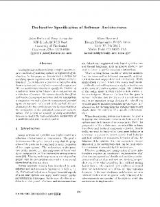
• Port. A port is a named and typed interaction point of a component. A provided port is typed by a provided interface, a required port by a required interface, and a complex port by an arbitrary set of provided and required interfaces. Complex ports enable the localization of complex interaction patterns where calls may occur in both directions. Unlike interfaces, a port may be associated with a behavior, specifying the externally observable behavior of the component when interacting through the port. This allows the specification of semantic contracts, similar to those described in Paper A. A component may have multiple ports typed by the same interface, and is able to distinguish between calls received through different ports. • Connector. A connector is a link that may be of kind delegation or assembly. A delegation connector either links a provided port of a component to a part of the component’s realization, signifying that requests received through the port is forwarded to the part, or it links a realization part to a required port, signifying that request sent through the port originates in the part. Several connections may exist between a single port and different realization parts. An assembly connector links a required interface or port of a component to a matching provided interface or port of another component. Figure 2-1 is a UML 2.0 diagram that illustrates these modeling elements. The diagram shows a component with one port, typed by one required and one provided interface. The component also has a realization, consisting of two component instances. Delegation connectors link the outer component’s port to a provided port of one of these instances and a required port of the other
2
Background
27
instance to the outer port. The two instances furthermore have ports linked by an assembly connector. The diagram does not show port names. Component1
Interface1
: Component2
Interface3
Interface1 Interface2
Interface2
Figure 2-1
Interface4
: Component3
Architectural modeling elements in UML 2.0.
The production of professional software architecture documentation has been studied at the Software Engineering Institute [14]. This work focuses more on the organization of architecture documents than on particular notations. The central organizing unit for such documents is that of a view, which is defined as follows: A view is a representation of a set of system elements and the relationships associated with them. Thus, a view represents a subset of the information contained in an architecture. The use of views is motivated by the fact that software
28
Use of Component-Based Software Architectures in Industrial Control Systems
architectures are complex entities that cannot be adequately described in a simple one-dimensional fashion. One of the most influential publications on architectural views is Kruchten’s paper on the 4+1 view model [28]. His approach, which has been adopted as a central part of the Rational Unified Process, defines the following views: • The logical view primarily supports behavioral requirements: the services the system should provide to its end users. • The process view addresses concurrency and distribution, system integrity, and fault tolerance. • The development view focuses on the organization of the software modules in the software development environment. • The physical view maps the various elements identified in the logical, process, and development views onto the processing nodes. • The use case view contains a small subset of important use cases, intended to show that the elements of the other four vies work together seamlessly. The last view is called the +1 view since it is redundant with, and serves to validate, the other views. Another model that has received considerable attention is sometimes called the Siemens 4 view architecture model and is a central part of Siemens Corporate Research’s approach, mentioned above. It defines the following views:
2
Background
29
• The conceptual view describes the system in terms of its major design elements and the relationships among them. • The module interconnection view describes functional decomposition and layering. • The execution view describes the dynamic structure of a system. • The code view describes how the source code, binaries, and libraries are organized in the development environment. The conceptual view has no direct counterpart in the 4+1 view model, while the module interconnection view corresponds roughly to the logical view, the execution view to the process and physical views, and the code view to the development view. The IEEE recommended practice for architectural description of softwareintensive systems (IEEE Standard 1471-2000) [13] focuses on the contents and intended use of architectural description documents. To this end, it defines a conceptual framework, which is illustrated in the UML class diagram in Figure 2-2. Thus, according to the standard, a system has an architecture, which is described by an architectural description. Furthermore, the system has a number of stakeholders, which each has a number of concerns, and the architectural description shall explicitly identify these stakeholders and their concerns. The architectural description must furthermore provide a rationale for the architecture and shall be organized into views.
30
Use of Component-Based Software Architectures in Industrial Control Systems
Figure 2-2
The conceptual framework for architectural description of IEEE Standard 1471-2000.
Each view must conform to what is called a viewpoint. A viewpoint is a general (i.e. system independent) template of a view, and is intended to address a certain subset of stakeholders and concerns. A view is a system specific instance of a viewpoint. The viewpoint specifies the format for describing the view, including languages and notations used as well as any analysis technique that may be applied. The architectural description shall state which viewpoints are used and present the specification of these or refer to other documents where specifications may be found. The standard emphasizes the potential for reuse of viewpoints, and therefore states that a viewpoint may be a library viewpoint. The architectural description is
2
Background
31
required to include at least one viewpoint and corresponding view, but there are no predefined compulsory views. It follows from this that the standard does not prescribe any particular language or notation.
2.2 Component-Based Software Engineering Component-based software engineering (CBSE) denotes the assembling of software products from pre-existing smaller products, generally called components. In particular when this is done using (de-facto) standard component models and supporting technologies. A component model generally defines a concept of components and rules for their design-time composition and/or run-time interaction, and is usually accompanied by one or more component technologies, implementing support for composition and/or interoperation.
2.2.1 Definitions of Software Components Within the field of software architecture there is a widely accepted terminology where the constituent parts of a system’s architecture are, in general, called components. This sometimes creates confusion since the architecture and CBSE communities have adopted the term component independently. A widespread view in CBSE is that component denotes a physical part (product), while in architecture a component can be any structural entity (file/class, process/thread, module/layer, etc.) and even purely conceptual (e.g. an abstraction invented by a designer). At the risk of
32
Use of Component-Based Software Architectures in Industrial Control Systems
adding to the confusion, this thesis uses the term component-based software architecture to mean a software architecture designed to support CBSE. One of the most influential definitions of software components (in the CBSE sense of the word) is that of Szypersky [1]: A software component is a unit of composition with contractually specified interfaces and explicit context dependencies only. A software component can be deployed independently and is subject to composition by third parties. The first part of the definition is technical, and states that software components should be “blackboxes” to be composed without modification (obviously, the definition means that interfaces and context dependencies are the only visible parts of the component). Szypersky asserts that source code modules do not qualify as software components since they make it possible for the composer to rely on implementation details, thus violating the principle of blackbox composition. The second part of the definition is more market-oriented, effectively stating that it should be possible to market software components as independent products and that buyers should be able to use them as parts in their own products. Naturally, independent deployment also has technical implications, namely that it must be possible to deploy (e.g. upgrade) a single component without any modification, recompilation, or similar of the rest of the systems of which the component is a part. In what is sometimes called The CBSE Handbook [2] Heineman and Councill present the following definition:
2
Background
33
A software component is a software element that conforms to a component model and can be independently deployed and composed without modification according to a composition standard. According to this definition, all components must conform to a component model, which the authors define as specifying interaction and composition standards. This requirement is quite reasonable, since it is hard to see how CBSE could work without some standards for interaction and composition. It is worth noting that the definition does not require that the component model is defined by a standards body or platform supplier, or that a commercial platform implementation is used. It is furthermore concluded that the two definitions principally agree, since the requirement that components can be modified without modification can only be satisfied if interfaces and context dependencies are well defined and that compliance with a standard naturally supports composition by third parties. Finally, a definition of software components that must be expected also to receive widespread attention is that of UML 2.0 [27], which has already been mentioned in this thesis. From the discussion of the previous section, the following definition can be extracted: A component is a modular unit with well-defined required and provided interfaces that is replaceable within its environment. The concept can be used to model both logical and physical components. In the context of CBSE, a software component corresponds to what UML 2.0 calls physical components. Although some will object to the use of the word physical to describe software components, this is the term used by the UML
34
Use of Component-Based Software Architectures in Industrial Control Systems
2.0 specification to denote deliverables such as COM+, EJB, or CCM components. The definition is somewhat broader than the previous two, as “replaceable within its environment” is a weaker requirement than “subject to independent deployment and composition by third parties”. The definition is interesting primarily as it helps to establish required and provided interfaces as part of the standard terminology of software component.
2.2.2 Software Component Models and Technologies As already mentioned, a software component model specifies standards for composition of and interaction between software components. To facilitate the use of such models, dedicated software tools and infrastructures are often implemented. These may include run-time environments for component execution and interaction as well as tools for component development, composition, and deployment. A software component technology is a set of dedicated software products supporting the use of a specific software component model. Heineman and Councill use the term component model implementation to denote the run-time parts of a software component technology. One of the most widely used component models is Microsoft’s Component Object Model (COM) [29]. Microsoft first used this model internally, in its Windows operating systems as well as in applications available on that platform, before releasing the COM specification. Thus, in this case, a component technology already existed when the component model was published. Today, there are numerous vendors of COM components and COM-based applications for the Windows platform. Technologies are also
2
Background
35
available on several other platforms, but COM has never gained widespread popularity outside the world of Windows. On the Windows platform, a COM component is an executable or dynamic link library (DLL) that implements a set of COM classes that each implements a set of COM interfaces. Classes may also have optional or required outgoing interfaces, i.e. interfaces to be used by the classes and implemented by other components. Both classes and interfaces are identified by globally unique identifiers (GUIDs), which are 128-bit numbers that can be generated by an algorithm that virtually ensures their uniqueness. The GUIDs of any classes implemented by the components installed on a system are stored in the Windows registry along with references to the implementing components. The COM library provides an API that an application or components, called a COM client, can use to create COM objects by supplying the GUIDs of the desired class and interface. COM does not specify how classes should be implemented. Instead, components are required to provide a factory interface that the COM library uses to instruct components to instantiate their own classes. What COM does specify is the binary format of interfaces. A client interacts with a COM object through a pointer to an interface node, which includes a pointer to a table of function pointers. Since the interface standard is binary, COM is oblivious to the programming languages use to implement components and clients. Once the COM library has created an object, it returns a pointer to one of the object’s interfaces to the client. The client can use an operation of this interface to request pointers to any other interfaces the object supports. This technique is called interface navigation. In addition, the COM specification includes a set of predefined interfaces for such purposes as
36
Use of Component-Based Software Architectures in Industrial Control Systems
scripting, error handling, and connection-oriented composition. Distributed COM (DCOM) [30] is an extension of COM that supports distributing applications across physical machines. The basic interoperability mechanisms of COM and DCOM are discussed more deeply in Paper C in this thesis. A special type of COM components is ActiveX controls [31]. These components implement and use predefined interfaces, which are designed to allow interaction with both (visual) composition tools and run-time environments, called containers. A typical application is in graphical user interface (GUI) controls, including controls automatically downloaded from web servers and executed in a web browser. Typically, such controls make use of outgoing interfaces to notify their containing application or web browser of events. A similar component model is Sun’s JavaBeans [32]. These components are built from Java classes that implement predefined interfaces and use special event objects for notification. JavaBeans share many of the characteristics of ActiveX controls, the main difference being that they must be written in the Java programming language [33] and executed on a Java virtual machine (JVM) [34]. Sun provides a solution that makes it possible to use JavaBeans in ActiveX containers. Component technologies related to ActiveX controls and JavaBeans include tools for packaging and deployment of components with associated resources and type information. COM+ [35] is an extension of COM incorporating support for services, such as transactional processing and message queuing, that are commonly used in distributed information systems. These services are not invoked programmatically from inside the components. Instead, declarative attributes can be associated with components and applications, specifying which services
2
Background
37
can or must be provided and at which level. The COM+ run-time system uses this information to intercept component interactions and insert system calls as required. This allows existing COM components to be transparently augmented with, for instance, transactional processing and used as part of COM+ applications. Another model providing similar services is Sun’s Enterprise JavaBeans (EJB) [36], which is based on Java but not on the aforementioned JavaBeans model. The required service levels for a set of EJB components are expressed declaratively in a file called a deployment descriptor. After deployment, each of the objects implemented by the components, generally called beans, live inside an EJB container, which also contains objects generated from the deployment descriptor. Clients invoke a bean’s operations via these generated objects, which ensure the correct service levels. Unlike JavaBeans, beans in EJB do not communicate through events. There are two principal types beans. Entity beans are used to encapsulate access to database records. An entity bean may implement its own persistence management or let the container manage persistence as specified by the deployment descriptor. Session beans, which may be stateful or stateless, represent interaction sessions with clients. Message-driven beans can be seen as a special kind of stateless session beans that represent asynchronous interaction session. A session bean may control transactions or leave that to the container. EJB requires the Java 2 Enterprise Edition (J2EE) platform [37]. A third model that is similar to COM+ and EJB is the CORBA Component Model (CCM) [38]. CCM is standardized by the Object Management Group (OMG) and require that clients and components communicate using an object
38
Use of Component-Based Software Architectures in Industrial Control Systems
request broker (ORB) as defined by version 3.0 of the OMG’s Common ORB Architecture (CORBA) [39]. A CCM component is delivered in a package, which contains a description in XML and possibly binaries for multiple platforms. A CCM application is an assembly of CCM and possibly EJB components, whose configuration is described in XML. A CCM component belongs to one of four possible categories. Service components correspond to stateless session beans in EJB, and maintain no state. Session components correspond to stateful beans and maintain state for the duration of a transaction. Entity components, as entity beans, encapsulate database access. Process components maintain persistent state throughout the lifetime of a process. Similarly to in EJB, the instances of a CCM component resides within a CCM container, and transaction control as well as persistence may be container managed or self managed. CCM components interact with clients and each other through attributes and port. A port is a facet, a receptacle, an event sources, or an event sink. Facets and receptacles are provided and required interfaces respectively. A facet of one component can be connected to a receptacle of another components. Event sources and sinks are connected via event channels. CCM also specify two predefined interfaces that are clearly inspired by COM. All component instances provide the equivalence interface for interface navigation and all components implement the home interface for instance creation. Koala [25] is a software component model specially intended for embedded software in consumer products. In particular, it is being used by Philips in products such as televisions and VCRs. A Koala component has a set of provided and required interfaces, and interacts with its environment through these interfaces only. A Koala configuration specifies a collection of
2
Background
39
component instances, the parts list, and a set of connections between these instances, the net list. In the simplest case, a connection links a required interface of one component instance to a matching provided interface of another component instance. Glue code may be associated with connections to provide more complex interactions. Configurations may themselves be used as components in a hierarchical fashion. Koala provides notations for specifying interfaces
and
components
and
a
graphical
language
for
defining
configurations. Basic Koala components, i.e. those that are not configurations, are sets of C source code files. As such they do not satisfy the definitions of software components discussed above. However, the motivation for using source code is efficiency and not exposition of implementation details, and the Koala configuration language encourages blackbox composition. The Koala compiler optimizes configurations by inserting into the code of the components static references to connected components wherever possible. Still, puritans may prefer to view Koala as a technology for modular, graphical programming rather than a component model. For instance, it does not support independent component deployment as discussed in the previous. As noted by e.g. Wallnau and others [40], software component models are closely related to the concept of architectural styles. Thus, as discussed in the previous section, one may expect the choice of a component model to affect a system’s properties in a predictable way. The component models discussed above each defines one or more types of components as well as different ways in which such components may be connected. Not surprisingly, the objectoriented systems style is evident in most of these models. This style corresponds directly to the way that EJB systems and most COM-based systems are organized. ActiveX, JavaBeans, and CCM correspond to an object-
40
Use of Component-Based Software Architectures in Industrial Control Systems
oriented, event-based systems style, which may also be used with COM/COM+. Recall that the primary assumed benefit of the object-oriented systems style is encapsulation of implementation details, while the eventbased systems style is assumed to result in increased extensibility. Koala differs from the other discussed models in that components are explicitly disallowed to contain references to other components. In a way, this resembles the pipe and filters style, and might be expected to promote reusability. A notable difference, which should not affect reusability however, is that the function calls flowing across Koala connections can result in bi-directional data flows. The definition of architectural style presented in the previous section states that a style might include one or more semantic models that allow a system’s properties to be inferred from the properties of its parts. No such models are included in any of the component models discussed above, and this seems also to be the case for other models. This is being addressed by the work on prediction enabled component technology (PECT), conducted at the Software Engineering Institute [41]. A PECT is defined as consisting of a constructive model, which, like the component models discussed so far, supports the implementation of systems as assemblies of components, and an analytical model, which defines techniques for predicting different properties of such assemblies from the properties of components.
2.2.3 Component-Based Software Engineering Practices As already mentioned, CBSE denotes the practice of assembling software from existing components. Thus, in comparison to traditional software engineering,
2
Background
41
the activity of assembling replaces that of programming. In practice, however, some programming is usually needed to make a set of independently developed component work together. Furthermore, traditional development models, where design and implementation follows strictly from a preceding stage of requirements identification, is less suited for CBSE, where it is usually necessary also to adjust requirements to match what available components can offer. For reference, Figure 2-3 is a simple UML activity diagram illustrating the traditional waterfall model of software development [42]. In more modern models, such as the Rational Unified Process [17], these activities are repeated iteratively. Requirements identification
Figure 2-3
Design
Implementation
Verification & Validation
Waterfall model of software development
Among the first to address the particular practices required for component-based software in a systematic fashion were Brown and Wallnau [43], who define a reference model for such systems. As illustrated in Figure 2-1, the model focuses on the system as a set of components that progresses through various states during development and evolution. Off-the-shelf components are pre-existing components that may have been acquired externally or reused from previous projects within the development organization. They are characterized by having hidden interfaces, where interface is interpreted to include not only a functional description but also all other information that is needed to use a component. Qualification is the process of discovering the hidden parts of the interfaces. The qualified components are subsequently adapted to remove architectural mismatch. This
42
Use of Component-Based Software Architectures in Industrial Control Systems
concept was first described by Garlan and others [44], and refers to mismatches between components originating from incompatible assumptions by the component designers about the system’s architecture. Adaptation is usually accomplished by writing wrappers. The adapted components are composed according to a selected architectural style. As discussed in the previous section, selecting a component model in part determines this architectural style. Composition may include writing some additional code, which is often call glue code. The system finally enters a stage of evolution where component may be updated.
qualification to discover interface
off-the-shelf components
Figure 2-4
adaptation to remove architectural mismatch
qualified components
composition into selected architectural style
adapted components
evolution to update components
assembled components
updated components
Reference model for architectural composition of components.
A central aspect of this model is the assumption that components initially have hidden interfaces, which is particularly important when using commercial components. This work has more recently been extended by Wallnau and others [45], with an even more pronounced focus on commercial
2
Background
43
components. A central concept of the work is that of an assembly, which is a set of interoperating components that may form part of a system. It is for instance argued that assemblies are more useful as units of evaluation and selection than individual components. In other component-based systems, as in that of the case study presented in this thesis, components are implemented to comply with pre-specified interfaces. In these cases, the activities of requirements identification and design will be less different from traditional software engineering, since there is no evaluation, selection, qualification, or adaptation of existing components. However, an essential goal of the design activity is to identify the components to be developed and allocate functionality to them. This can be seen as input for identifying requirements for each component, which can subsequently be independently developed and tested. This leads to a form of nested development process where similar activities are performed on both system and component levels. Based on the waterfall model in Figure 2-3, this can be depicted as in Figure 2-5. Requirements identification
Requirements identification #1
Implementation (assembly)
Verification & Validation
Design #1
Implementation #1
Verification & Validation #1
Design #n
Implementation #n
Verification & Validation #n
Design
… Requirements identification #n
Figure 2-5
Waterfall model adopted for component-based software development.
44
Use of Component-Based Software Architectures in Industrial Control Systems
In addition to the practices of developing component-based system, the literature also discusses non-technical aspects of CBSE. For instance, Szyperski [1] points out that a component market of critical size is needed for the development of commercial components to represent a viable business opportunity. Another example is Heineman and Councill’s book [2], which covers regulatory and legal issues, such as the applicability of commercial law to software components.
2.3 Industrial Control Systems Simply put, industrial control systems are computer systems that control physical processes and equipment. More specifically, this thesis is concerned with the types of system used in the control of industrial plants. In practically all cases, these are distributed systems in which control functions are performed by several nodes that communicate via different types of networks. Typically, these nodes also communicate with other computer systems, such as different types of servers and workstations.
2.3.1 Levels of Industrial Control Systems Figure 2-6 illustrates a typical configuration of interconnected information processing and control nodes in an industrial system. The controllers and field devices are furthermore connected to physical processes and equipment to be controlled.
2
Background
45
Workplaces (Thin clients)
Internet
Firewall
Workplaces (Thin or rich clients)
Intranet
Server
Workplaces (Rich clients)
Router
Client/server Network Servers
Control Network Controllers
Fieldbus Field devices
Figure 2-6
Typical configuration of industrial information and control systems.
This system comprises different types of computers and other devices that communicate over different networks. The client/server network is used for communication between servers and between servers and workplaces. In some cases, a computer may be used as both a server and a workplace. The network may be connected to an intranet via a router and further to the Internet via a firewall. The control network connects servers and controllers. In small systems, the control and client/server networks may be combined in one physical network. Different types of fieldbuses are used to interconnect field
46
Use of Component-Based Software Architectures in Industrial Control Systems
devices and to connect them to the rest of the system, either via controllers as the figure shows or directly to servers. In some cased, fieldbuses and the control network may share the same physical medium. It is customary to divide the functionality of this kind of systems into levels, where the functions of each level depend on those of the lower levels. • The workplace level comprises different types of user interaction. A typical example is the software used by operators in control rooms to view and possibly alter the state of the controlled processes. This level also includes applications for such task as analysis of process data and configuration of process equipment. Applications usually run on PCs or other types of workstations, which may be attached to the client/server network, an intranet, or the Internet. • A central function of the server level is to collect and store process data, which is used by different types of applications. These are typically client-server applications where data presentation is implemented on the workplace level and the majority of computation and storage on the server level. In addition, data and commands, possibly originating in the Workplace level, may be sent to process equipment. The server level may also include functions, such as optimization, that determine longterm control strategies. The server machines that provide this functionality is connected to the client/server network and, at least some of them, to the control network. • The main function of the control level is the execution of control software by dedicated controllers. Typically, these repeatedly read values from
2
Background
47
sensors and computes values to be written to actuators. Control applications may be much more complex, however, for instance including sophisticated communication with other devices. Controllers are attached to the control network and possibly to fieldbuses. • The field level comprises functions performed by different types of field devices. The simplest of these are I/O modules, which perform translations between physical signals and controller data. There may also be more advanced devices, such as smart sensors and actuators, which may be connected to a controller or directly to a server. Field devices communicate over fieldbuses. These levels are defined from the premise that the functions within each may require the presence of functions at lower levels but should be able to operate independently of higher-level functions. In addition, the functions within each level share characteristics that affect (among other things) the design of the software that implements them. One example is the different real-time and performance requirements. As discussed further in the following section, the control and field levels are dominated by hard and soft real-time deadlines. This often mandates the use of real-time operating systems. To ensure availability, redundant hardware architectures may be used, in which the actual control of the process is performed by a primary processor, with additional processors working in stand-by mode and able to take over in case the primary processor fails. Although the functions in the server layer may also be subject to response-time requirements, they tend to be dominated by a desire to maximize average throughput. Thus, they are usually implemented on top of general-purpose operating systems, such as Windows or Unix, and
48
Use of Component-Based Software Architectures in Industrial Control Systems
other platform products, such as database management systems. This furthermore makes the use of component technologies, such as COM+ and EJB, a realistic possibility. Redundancy may also be employed at this level, typically in the form of server groups. Unlike in the redundant architectures used at the lower levels, the servers in a group usually perform load balancing. Thus, if one server fails, the system will continue to operate with reduced performance. The user interface functions of the workplace level are usually not subject to real-time requirements. They are often implemented using graphical design tools and possibly such technologies as ActiveX controls and JavaBeans. Another characterizing feature of the levels is the difference in product life cycles. As a general rule, hardware and software components at lower levels are updated less often than at higher levels. According to experiences from ABB, applications have a life span of 3–5 years at the workplace level, 5–8 years at the server level, 8–15 years at the controller level, and 10–20 years at the field level. One result of this is that applications at one level are often required to work with legacy applications at lower levels, but less often at higher levels. For instance, new releases of client applications at the workplace level typically need to work with existing server software, while it is more common for new releases of server software also to require updated client applications. On the other hand, new server releases are usually required to support legacy hardware and software at the control and field levels. This difference in life cycles is in part motivated by the unidirectional dependence between the levels, which means that updates at one level is likely to disturb functions at all higher levels. Thus, in general, upgrades at lower levels entail more widespread disturbances and associated costs. Another factor that tend
2
Background
49
to make product updates more costly at, in particular, the control and field levels, is the possible need of disrupting the controlled process. As already mentioned, applications at the workplace and server levels are often organized as client-server applications, where the server level is responsible for any communication with controllers and field devices. To simplify the implementation of client applications that can work with equipment from different vendors, a COM-based standard called OLE for process control (OPC) [46] has been created. OPC defines a set of COM interfaces for supporting basic data access as well as such functionality as alarm and event handling, historic data access, batch processing, etc. Many vendors of process equipment now provide OPC servers that implement (a subset of) these interfaces, which client applications can access using DCOM. The OPC standard is managed by an industry association called the OPC Foundation, which has over 300 member organizations and lists more than 250 manufacturers of OPC-compliant products. A standard that can be used for communication between servers and controllers is the manufacturing message specification (MMS) [47], which specifies services suitable for such applications as data exchange and download of control software. As for the field level, a number of fieldbuses have been standardized [48], some of which are particularly popular within certain industry sectors or geographical areas. A strong current trend is the increased popularity of fieldbuses based on standard network technology, such as TCP/IP and Ethernet.
50
Use of Component-Based Software Architectures in Industrial Control Systems
2.3.2 Programmable Controllers As stated in the previous section, control software is usually executed on controllers, equipped with physical interfaces for reading from sensors and writing to actuators. Control applications can be categorized into continuous, discrete, and hybrid control. In the first category, a controller samples continuous signals at regular intervals and computes streams of data to produce approximations of continuous output signals. An example application is the control of a valve to keep the flow of a fluid constant in the presence of varying supply pressure. In the second category, the controller reacts to discrete events and affect discrete actions. For instance, a controller could detect the level of fluid in a tank reaching minimum or maximum levels, and turn the supply on or off accordingly. Hybrid control applications combine both the other two types of control. Continuous control applications can further be divided into closed-loop control and open-loop control. In the case where a single output of a physical process is being controlled using closed-loop control, the controller measures this output, called the controlled variable, and compares it with the desired value, the reference. Based on the difference, an input signal to the process, called the manipulated variable, is produced to drive the output in the desired direction. In this way, the controller can make the process output track a variable reference, or keep it constant in the presence of external disturbances. Figure 2-7 illustrates the principle, which is also known as feedback control. For simplicity, sensors and actuators are not shown, but taken to be part of the controller.
2
Background
51
Disturbance
Reference
Figure 2-7
Controller
Manipulated variable
Process
Controlled variable
Closed-loop control system.
In some cases, it may be advantageous to use the principle of open-loop control. As illustrated in Figure 2-8, the controller measures the disturbance and sets the manipulated variable so as to keep the process output equal to the reference. Clearly, this requires that the process is well understood so that the combined effect of the measured disturbance and the computed input can be accurately predicted. This principle is also known as feed-forward control. In addition to such pure closed-loop and open-loop applications as presented here, there are applications where both the disturbance and the process output are measured. Also, there are multi-variable control applications in which multiple process variables are measured and controlled. Disturbance
Reference
Figure 2-8
Controller
Manipulated variable
Process
Controlled variable
Open-loop control system.
In the purest form of discrete control, the controller is only equipped with digital (i.e. binary) inputs and outputs, and the control software can be viewed
52
Use of Component-Based Software Architectures in Industrial Control Systems
as emulating digital electronic circuits. This has been utilized in graphical programming tools. Figure 2-9 shows a simple example of such a program in which the output Run becomes true when the input Start becomes true, and then stays true until the input Stop becomes true. The block marked “≥1” is a logical or-gate and the block marked “&” is a logical and-gate with its lower input inverted.
Start
≥1
&
Run
Stop
Figure 2-9
Example logic for discrete control system.
In continuous control loops, the process is usually modeled as a system of differential equations, with the inputs and outputs being functions of time. Often, the controls software is also implemented so as to approximate a system of differential equations. The modeling of physical processes and design of control equations is the topic of control theory [5]. For the techniques of control theory to be useful, it is essential that the frequency with which the controller reads input signals and updates output signals, the sampling frequency, is sufficiently high to ensure faithful approximation of the control equations. Obviously, this translates into a real-time deadline on the computations the controller performs at each sample. In a programmable controller product, the application programmer should be able to set the sampling frequency (within a certain supported interval), and this frequency should be guarantied with some accuracy. This leads to hard real-time deadlines in the design of the
2
Background
53
controller product. In discrete and hybrid control, real-time requirements are also common to ensure the timing of actions in relation to events. Traditionally, controller products have been designed for either continuous or discrete control. Two important categories of programmable controller products have been distributed control systems (DCSs) for continuous control and programmable logic controllers (PLCs) for discrete control. In the past, PLCs usually only supported simple computations on digital data, and the costs for these were considerably lower than for DCSs, which were required to perform at least numerical computations. However, the dramatic reduction in the price of computing hardware has resulted in both more sophisticated PLCs and less expensive DCSs. These trends have lead to a convergence of these product categories into a single category of products often called programmable controllers. Such products still vary noticeably in price, functionality, and other attributes, though. Some concepts of programmable controllers have been standardized in the industry standard IEC 61131 [49]. In particular, the part of the standard called IEC 61131-3 [50] standardizes a programming model and a set of programming languages. This set comprises the graphical languages Ladder Diagram (LD), Function Block Diagram (FBD), and Sequential Function Chart (SFC), and the textual languages Instruction List (IL) and Structured Text (ST). All languages share a set of standard data types for representing Booleans, character strings, date and time values, numbers, enumerations, arrays, and structures. In addition, the programming model supports three kinds of program organizing units (POUs), called programs, function blocks, and functions.
54
Use of Component-Based Software Architectures in Industrial Control Systems
Functions take input parameters and provide a return value in the normal way. They can be written in any of the above languages except SFC. Function blocks are instances of function block types. A function block type consists of a declaration part and an implementation part. The declaration part defines variables, which may be of type input, output, input/output, internal, external, or temporal, and possibly a set of instances of other function blocks. External variables are references to variables defined outside the function block. Temporal variables are allocated and initialized at every invocation of an instance. An example declaration part of a function block is shown below.
FUNCTION_BLOCK PID VAR_INPUT Kp : REAL;
(* Proportional gain *)
Ki : REAL;
(* Integral gain *)
Kd : REAL;
(* Differential gain *)
T : REAL;
(* Sampling interval *)
Input : REAL;
(* Actual process value *)
Reference : REAL;
(* Desired process value *)
END_VAR; VAR_OUTPUT Output : REAL;
(* Controller output *)
END_VAR; VAR Error : REAL;
(* Difference between actual and desired *)
Error_old : REAL := 0;
(* Error of previous sample *)
Sum : REAL := 0;
(* Accumulated error *)
2
Background
55
END_VAR; END_FUNCTION_BLOCK;
This function block type defines a number of input, output, and internal variables, necessary to implement a proportional-integral-differential (PID) controller, which is a very common type of controller used in closed-loop control applications. Viewing the difference between the process output and the reference (the error signal) as a continuous function e(t) of time, a PID controller computes an approximation of a process input m(t) defined by: t
m(t ) = K P e(t ) + K I ∫ e(τ ) dτ + K D 0
de(t ) dt
A function block implementation can be written in any of the available languages. The implementation is executed once every time a function block is invoked. A simple implementation of the PID controller in Structured Text is shown below.
Error := Reference – Input; Sum := Sum + Error; Output = Kp*Error + Ki*Sum*T + Kd*(Error – Error_old)/T; Error_old := Error;
As
one
would
expect,
input
variables
are
read-only
within
the
implementation. In addition to primitive statements, function block implementations may contain function and function block invocations. The
56
Use of Component-Based Software Architectures in Industrial Control Systems
rules that govern the execution of function blocks are the same as those for programs, which are discussed in the following. Programs are instances of program types, which, like function block types, have declaration and implementation parts. A program’s declaration part declares variables and function block instances as illustrated in the example below. A variable can either be of one of the kinds used in a function block declaration or it can be a global variable or an access variables. These additional kinds of variables are explained later.
PROGRAM PIDLoop VAR Kp : REAL;
(* Proportional gain *)
Ki : REAL;
(* Integral gain *)
Kd : REAL;
(* Differential gain *)
T : REAL;
(* Sampling interval *)
Input : REAL AT %IW01;
(* Actual process value *)
Ref : REAL;
(* Desired process value *)
Output : REAL AT %QW01; (* Controller output *) (* Function blocks *) PID1 : PID;
(* PID controller *)
Scale1 : ScaleIn;
(* Scaling and conversion of input *)
Scale2 : ScaleOut;
(* Scaling and conversion of output *)
END_VAR; END_PROGRAM;
2
Background
57
This program can be used to implement a PID control loop on a controller equipped with an input unit that produces integer data and a corresponding output unit. To achieve this it uses the PID function block from above and two other function blocks for conversion and scaling of data between the formats used by I/O units and the PID function block. Notice how the variables Input and Output are connected to the addresses of the I/O units using a special syntax. This makes the Input variable read-only. An implementation of the program in the Function Block Diagram language is show in Figure 2-10. Each function block instance appears on the diagram as a rectangle with inputs on the left and outputs on the right. Similar symbols are used for operations and function calls, which are not named. Lines are used to connect these entities to each other and to variables and constants. Outputs of all entities are read-only. In the typical case, all entities are invoked from left to right once every time the program executes, although function block execution may be configured otherwise, as described later. Program and function block implementations may include multiple instances of the same function block type, in which case each instance maintains its own copies of all variables except those that are declared as external. PID1 : PID
Scale1 : ScaleIn Input
In
Kp
Kp
Ki
Ki
Ki
Ki
T
T Input
Out Ref
Figure 2-10
Function Block Diagram.
Reference
Scale2 : ScaleOut Output
In
Out
Output
58
Use of Component-Based Software Architectures in Industrial Control Systems
To control how programs and function blocks are executed on a controller, IEC 61131 defines the concepts of configurations, resources, and tasks. A configuration contains all the run-time entities of a single physical controller, which, at the top level, consists of one or more resources and zero or more variables. Each resource is a virtual run-time environment that controls some percentage of the processor time. A resource contains one or more program instances, zero or more tasks, and zero or more variables. The variables declared by configurations and resources are either global variables or access variables. Recall that programs can also declare such variables. Global variables are accessible to all elements in the declaring context through the use of external variable declarations. Access variables are accessible from other controller via communication services. Such services are specified in IEC 61131-5 [51]. Similarly to external variable declarations, access variable declarations are references to variables declared elsewhere. Configurations and resources may also define resource specific initializations, which specifies initial values for variables of contained program and function block instances and overrides any initializations specified by their types. The UML class diagram in Figure 2-11 illustrates the run-time elements of a controller and their relationships. Tasks represent concurrent threads of execution within a resource and can be periodic or event-driven or both. Each task has an associated priority, each periodic task an associated period time, and each event-driven task an associated Boolean variable. A program or function block instance may be assigned to a task, and each task attempts to execute the instances assigned to it once every period and/or at each event occurrence. For instance, the PIDLoop program above must be assigned to a periodic task with a period equal to the
2
Background
59
specified sampling interval in order to work as intended. Scheduling of tasks is priority based and may be preemptive or non-preemptive. Preemptive scheduling always gives access to the available processor resources to the task with the highest priority among those that are ready to execute their instances. This may involve suspending (i.e. preempting) an already executing task with lower priority. Non-preemptive scheduling lets an already executing task finish, even if tasks with higher priority become ready. Programs that are not explicitly assigned to a task can be though of as being implicitly assigned to a task that has lower priority than any other tasks and is always ready to execute. Thus, the presence of such programs results in 100% utilization of the resource’s processor time. A function block that is not explicitly assigned to a task is executed once every time its containing program or function block is executed.
Figure 2-11
Run-time entities of the IEC 61131 programming model
3 Paper A: Specification of Software Components Frank Lüders Mälardalen University, Department of Computer Engineering, Sweden
[email protected] Kung-Kiu Lau and Shui-Ming Ho University of Manchester, Department of Computer Science, UK {kung-kiu, sho}@cs.man.ac.uk
3.1 Introduction In its simplest form a software component contains some code (that can be executed on certain platforms) and an interface that provides (the only) access to the component. The code represents the operations that the component will perform when invoked. The interface tells the component-user everything he needs to know in order to deploy the component. Components can of course be deployed in many different contexts. Ideally, components should be black boxes, to enable users to (re)use them without needing to know the details of their inner structure. In other words, the interface of a component should provide all the information needed by its users. Moreover, this information should be the only information they need. Consequently, the interface of a component should be the only point of access to the component. It should therefore contain all the information that users
61
62
Use of Component-Based Software Architectures in Industrial Control Systems
need to know about the component's operations (that is, what its code enables it to do) and its context dependencies (that is, how and where the component can be deployed). The code, on the other hand, should be completely inaccessible (and invisible), if a component is to be used as a black box. The specification of a component is therefore the specification of its interface. This must consist of a precise definition of the component's operations and context dependencies and nothing else. Typically, the operations and context dependencies will contain the parameters of the component. The specification of a component is useful to both component users and component developers. For users, the specification provides a definition of its interface, viz. its operations and context dependencies. Since it is only the interface that is visible to users, its specification must be precise and complete. For developers, the specification of a component also provides an abstract definition of its internal structure. Whilst this should be invisible to users, it is useful to developers (and maintainers), not least as documentation of the component. In this chapter, we discuss the specification of software components. We will identify all the features that should be present in an idealized component, indicate how they should be specified, and show how they are specified using current component specification techniques.
3
Paper A: Specification of Software Components
63
3.2 Current Component Specification Techniques The specifications of components used in practical software development today are mostly limited to what we will call syntactic specifications. This form of specification includes the specifications used with technologies such as Microsoft’s Component Object Model (COM) [29], the Object Management Group’s Common Object Request Broker Architecture (CORBA) [52], and Sun’s JavaBeans [32]. The first two of these use different dialects of the Interface Definition Language (IDL) while the third uses the Java programming language to specify component interfaces. In this section, COM is mainly used to illustrate the concepts of syntactic specification of software components. First, we take a closer look at the relationships between components and interfaces. A component provides the implementation of a set of named interfaces, or types, each interface being a set of named operations. Each operation has zero or more input and output parameters and a syntactic specification associates a type with each of these. Many notations also permit a return value to be associated with each operation, but for simplicity we do not distinguish between return values and output parameters. In some specification techniques it is also possible to specify that a component requires some interfaces, which must be implemented by other components. The interfaces provided and required by a component are often called the incoming and outgoing interfaces of the component, respectively.
64
Use of Component-Based Software Architectures in Industrial Control Systems
Component *
0..1 * 1
*
Name
in-interfaces *
Interface 1
0..1
1
*
out-interfaces
* Operation * 1 * Type
Parameter 1
*
InParameter
OutParameter
InOutParameter
Figure 3-1
UML metamodel of the concepts used in syntactic specification of software components.
Figure 3-1 is a UML class diagram [26] showing the concepts discussed above and the relationships between them. Note that instances of the classes shown on the diagram will be entities such as components and interfaces, which can themselves be instantiated. The model is therefore a UML metamodel, which can be instantiated to produce other models. It is worth
3
Paper A: Specification of Software Components
65
noting that this model allows an interface to be implemented by several different components, and an operation to be part of several different interfaces. This independence between interfaces and the components that implement them is an essential feature of most component specification techniques. The possibility of an operation being part of several interfaces is necessary to allow inheritance, or subtyping, between interfaces. The model also allows parameters to be simultaneously input and output parameters. The model presented above is intended to be a generic representation of the relationships between components, interfaces, and operations. In practice, these relationships vary between specification techniques. For example, one can distinguish between object-oriented specifications and what might be called procedural specifications. In this chapter we will only consider objectoriented specifications that are used by current technologies. This leads to no loss of generality, as procedural specification can be seen as a special case of object-oriented specification. There are subtle differences in the precise nature of the relationship between a component and its interfaces in different objectoriented specification techniques. In COM, for example, a component implements a set of classes, each of which implements a set of interfaces. The statement that a component implements a set of interfaces thus holds by association. In more traditional object-oriented specification techniques, a component is itself a class that has exactly one interface. The statement that a component implements a set of interfaces still holds, because this interface can include, or be a subtype of, several other interfaces. As an example of a syntactic specification, we now consider the specification of a COM component. Below is a slight simplification of what
66
Use of Component-Based Software Architectures in Industrial Control Systems
might be the contents of an IDL file. First, two interfaces are specified, including a total of three operations which provide the functionality of a simple spell checker. Both interfaces inherit from the standard COM interface IUnknown. (All COM interfaces except IUnknown must inherit directly or indirectly from IUnknown. See [29] for more information about the particulars of COM.) All operations return a value of type HRESULT, which is commonly used in COM to indicate success or failure. A component is then specified (called a library in COM specifications), this implementing one COM class, which in turn implements the two interfaces previously specified. This component has no outgoing interfaces. interface ISpellCheck : IUnknown { HRESULT check([in] BSTR *word, [out] bool *correct); }; interface ICustomSpellCheck : IUnknown { HRESULT add([in] BSTR *word); HRESULT remove([in] BSTR *word); }; library SpellCheckerLib { coclass SpellChecker { [default] interface ISpellCheck; interface ICustomSpellCheck;
3
Paper A: Specification of Software Components
67
}; }; Relating this specification to the model above, there is one instance of Component, which is associated with two instances of Interface. Taking a closer look at the first interface, it is associated with a single instance of Operation, which is itself associated with one instance of InParameter and two instances of OutParameter, representing the two named parameters and the return value. The information that can be obtained from a component specification such as the above is limited to what operations the component provides, and the number and types of their parameters. In particular, there is no information about the effect of invoking the operations, except for what might be guessed from names of operations and parameters. Thus, the primary uses of such specifications are type checking of client code and as a base for interoperability between independently developed components and applications. Different component technologies have different ways of ensuring such interoperability. For example, COM specifies the binary format of interfaces while CORBA defines a mapping from IDL to a number of programming languages. An important aspect of interface specifications is how they relate to substitution and evolution of components. Evolution can be seen as a special case of substitution where a newer version of a component is substituted for an older version. Substituting a component Y for a component X is said to be safe if all systems that work with X will also work with Y. From a syntactic viewpoint, a component can safely be replaced if the new component implements at least the same interfaces as the older components, or, in traditional object-oriented terminology, if the interface of the new component is a subtype
68
Use of Component-Based Software Architectures in Industrial Control Systems
of the interface of the old component. For substitution to be safe however, there are also constraints on the way that the semantics of operations can be changed, as we shall see in the next section.
3.3 Specifying the Semantics of Components While syntactic specifications of components are the only form of specifications in widespread use, it is widely acknowledged that semantic information about a component’s operations is necessary to use the component effectively. Examples of such information are the combinations of parameter values an operation accepts, an operation’s possible error codes, and constraints on the order in which operations are invoked. In fact, current component technologies assume that the user of a component is able to make use of such semantic information. For instance, COM dictates that the error codes produced by an operation are immutable, i.e. changing these is equivalent to changing the interface. These technologies do not, however, support the specification of such information. In the example with COM, there is no way to include information about an operation’s possible error codes in the specification. Several techniques for designing component-based systems that include semantic specifications are provided in the literature. In this section, we shall examine the specification technique presented in [53], which uses UML and the Object Constraint Language (OCL) [54] to write component specifications. OCL is included in the UML specification. Another well-known method that uses the same notations is Catalysis [55]. The concepts used for specification of components in these techniques can be seen as an extension of the generic
3
Paper A: Specification of Software Components
69
model of syntactic specification presented in the previous section. Thus, a component implements a set of interfaces that each consists of a set of operations. In addition, a set of pre-conditions and post-conditions is associated with each operation. Pre-conditions are assertion that the component assumes to be fulfilled before an operation is invoked. Post-conditions are assertions that the component guarantees will hold just after an operation has been invoked, provided the operation’s pre-conditions were true when it was invoked. In this form of specification, nothing is said about what happens if an operation is invoked while any of its pre-conditions are not fulfilled. Note that pre- and post-conditions is not a novel feature of component-based software development, and is used in a variety of software development techniques, such as the Vienna Development Method [56] and Design by Contract [57]. Naturally, an operation’s pre- and post-conditions will often depend on state maintained by the component. Therefore, the notion of an interface is extended to include a model of that part of a component’s state that may affect or be affected by the operations in the interface. Now, a pre-condition will in general be a predicate over the operation’s input parameters and this state, while a post-condition is a predicate over both input and output parameters as well as the state just before the invocation and just after. Furthermore, a set of invariants may be associated with an interface. An invariant is a predicate over the interface’s state model that will always hold. Finally, the component specification may include a set of inter-interface conditions, which are predicates over the state models of all the component’s interfaces.
70
Use of Component-Based Software Architectures in Industrial Control Systems
Constraint
Component *
1
*
*
*
*
* State
1
Interface 1
out-interfaces
* 1
1
1
in-interfaces *
*
* Invariant *
*
*
PreCondition
Operation *
1
PostCondition 1
*
*
1
*
*
*
*
InParameter
Parameter
*
*
OutParameter
*
Figure 3-2
UML metamodel of the concepts used in semantic specification of software components.
The concepts introduced here and the relationships among them are shown on the UML class diagram in Figure 3-2. For the sake of readability, the classes Name, Type, and InOutParameter are not shown, since they have no direct relationships with the newly introduced classes. Note that this model allows the same state to be associated with several interfaces. Often, the state models of different interfaces of a component will overlap rather than be exactly the
3
Paper A: Specification of Software Components
71
same. This relationship cannot be expressed in the model since we cannot make any assumptions about the structure of state models. Note also how each post-condition is associated with both input and output parameters and only one instance of State. The states before and after an invocation are represented by two separate instances of this single instance of (the metaclass) State. In the model presented above, a partial model of the state of a component is associated with each interface, to allow the semantics of an interface’s operations to be specified. It is important to note that this is not intended to specify how state should be represented within the component. While state models in component specifications should above all be kept simple, the actual representation used in the component’s implementation will usually be subject to efficiency considerations, depend on the programming language, and so on. It is also worth mentioning that the above model is valid for procedural as well as object-oriented specification techniques.
«interface type» ISpellCheck check(in word : String, out correct : Boolean) : HRESULT
«interface type» ICustomSpellCheck add(in word : String) : HRESULT remove(in word : String) : HRESULT
Figure 3-3
words String 1
*
words String 1
*
Example interface specification diagram.
Before discussing the ramifications of this model any further, we now look at an example specification using the technique of [53]. Figure 3-3 is an example of an interface specification diagram. It shows the two interfaces
72
Use of Component-Based Software Architectures in Industrial Control Systems
introduced in the previous section as classes with the stereotype. Thus, all the information in the syntactic interface specifications is included here. The state models of the interfaces are also shown. A state model generally takes the form of one or more classes having at least one composition relationship with the interface the state belongs to. The special stereotype is used instead of the standard since this would
not allow the state models to be associated with the interfaces in this way. The interface specification diagram is only a part of the complete interface specifications. The pre- and post-conditions that specify the semantics of the operations as well as any invariants on the state model is specified separately in OCL. Below is a specification of the three operations of the two interfaces above. There are no invariants on the state models in this example. context ISpellCheck::check(in word : String, out correct : Boolean) : HRESULT pre: word " " post: SUCCEEDED(result) implies correct = words->includes(word) context ICustomSpellCheck::add(in word : String) : HRESULT pre: word " " post: SUCCEEDED(result) implies words = words@pre->including (word) context ICustomSpellCheck::remove(in word : String) : HRESULT pre:
3
Paper A: Specification of Software Components
73
word " " post: SUCCEEDED(result) implies words = words@pre->exluding(word) The pre-condition of the first operation states that if it is invoked with an input parameter that is not the empty string, the post-condition will hold when the operation returns. The post-condition states that if the return value indicates that the invocation was successful then the value of the output parameter is true if word was a member of the set of words and false otherwise. The specifications of the two last operations illustrate how post-conditions can refer to the state before the invocation using the @pre suffix. This specification technique uses the convention that if a part of an interface’s state is not mentioned in a post-condition, then that part of the state is unchanged by the operation. Thus, words = words@pre is an implicit post-condition of the first operation. All the specifications refer to an output parameter called result, which represents the return value of the operations. The function SUCCEEDED is used in COM to check whether a return value of type HRESULT indicates success or failure. Similarly to interface specification diagrams, component specification diagrams are used to specify which interfaces components provide and require. Figure 3-4 is an example of such a diagram, specifying a component that provides the two interfaces specified above. The component is represented by a class with stereotype to emphasize that it represents a component specification. UML also has a standard component concept, which is commonly used to represent a file that contains the implementation of a set of concrete classes.
74
Use of Component-Based Software Architectures in Industrial Control Systems
«comp spec» SpellChecker
Figure 3-4
ISpellCheck ICustomSpellCheck
Example component specification diagram.
The component specification is completed by the specification of its interinterface constraints. The component in this example has one such constraint, specifying that the sets of words in the state models of the two interfaces must be the same. This constraint relates the operations of the separate interfaces to each other, such that invocations of add or remove affect subsequent invocations of check. The constraint is formulated in OCL below. context SpellChecker ISpellCheck::words = ICustomSpellCheck::words An important property of the model presented above is that state models and operation semantics are associated with interfaces rather than with a component. This means that the semantics is part of the interface specification. Consequently, a component cannot be said to implement an interface if it implements operations with the same signatures as the interface’s operations but with different semantics. It should be noted that the terminology varies in the literature on this point, as interfaces are sometimes seen as purely syntactic entities. In such cases, specifications that also include semantics are often called contracts. UML, for instance, defines an interface to be a class with only abstract operations, which can have no state associated with it. While the main uses of syntactic specifications are type checking and ensuring interoperability, the utility of semantic specifications is potentially
3
Paper A: Specification of Software Components
75
much larger. The most obvious use is perhaps tool support for component developers as well as developers of component-based application. For the benefit of component developers, one can imagine an automatic testing tool that verifies that all operations produce the correct post-conditions when their pre-conditions are satisfied. For this to work, the tool must be able to obtain information about a component’s current state. A component could easily be equipped with special operations for this purpose, which would not need to be included in the final release. Similarly, for application developers, one can imagine a tool that generates assertions for checking that an operation’s preconditions are satisfied before the operation is invoked. These assertions could either query a component about its current state, if this is possible, or maintain a state model of their own. The last technique requires that other clients do not affect the state maintained by a component, however, since the state model must be kept synchronized with the actual state. Such assertions would typically not be included in a final release, either. With a notion of interface specification that include semantics, the concept of substitution introduced in the previous section can now be extended to cover semantics. Clearly, if a component Y implements all the (semantically specified) interfaces implemented by another component X, then Y can be safely substituted for X. This condition is not necessary, however, for substitution to be safe. What is necessary is that a client that satisfies the preconditions specified for X will always satisfy the pre-conditions specified for Y, and that the client can rely on the post-conditions ensured by X also to be ensured by Y. This means that Y must implement operations with the same signatures as the operations of X, and with pre- and post-conditions that ensures the condition above. More specifically, if X implements an operation
76
Use of Component-Based Software Architectures in Industrial Control Systems
O, where pre(O) is the conjunction of its pre-conditions and post(O) the conjunction of its post-conditions, Y must implement an operation O’ with the same signature such that pre(O’) implies pre(O) and post(O) implies post(O’). In other words, the interfaces implemented by Y can have weaker preconditions and stronger post-conditions than the interfaces implemented by X. It follows from this that the state models used for specifying the interfaces of X and Y need not be identical. This condition for semantically safe substitution of components is an application of Liskov’s principle of substitution [58]. Note that the above discussion is only valid for sequential systems. For multi-threaded components or components that are invoked by concurrently active clients, the concept of safe substitution must be extended as discussed in [59]. Finally, it must be noted that a client may still malfunction after a component substitution, even if the components fulfill semantic specifications that satisfy the above condition. This can happen, for instance, if the designers of the client and the new component have made conflicting assumptions about the overall architecture of the system. The term “architectural mismatch” has been coined to describe such situations [44]. The component specification diagram in Figure 2.4 shows how we can indicate which interfaces are offered by a component. In this example, we indicated that the spell checker offered the interfaces ISpellCheck and ICustomSpellCheck and used the constraint ISpellCheck::words = ICustomSpellCheck::words
3
Paper A: Specification of Software Components
77
to specify that the interfaces act upon the same information model. We could, however, extend such diagrams to indicate the interfaces on which a component depends. This is illustrated in Figure 3-5. ISomeInterface
SomeComponent
IAnotherInterface
IUsedInterface
Figure 3-5
Component specification showing an interface dependency.
We can also specify realization contracts using collaboration interaction diagrams. For example, in Figure 3-6 we state that whenever the operation op1 is called, a component supporting this operation must in invoke the operation op2 in some other component. Component specification diagrams and collaboration interaction diagrams may therefore be used to define behavioral dependencies. 1: op1
/ISomeInterface 1.1: op2 /IUsedInterface
Figure 3-6
Collaboration interaction diagrams.
78
Use of Component-Based Software Architectures in Industrial Control Systems
3.4 Specifying Extra-Functional Properties of Components The specification of extra-functional properties of software components has recently become a subject of interest, mainly within the software architecture community. In [60], it is argued that the specification of architectural components is not properly addressed by conventional software doctrine. Architectural components are components of greater complexity than algorithms and data structures. Software components, as defined above, generally belong to this class. Conventional software doctrine is the view that software specifications must be sufficient and complete (say everything a user needs to know and is permitted to rely on about how to use the software), static (written once and frozen), and homogeneous (written in a single notation). To use an architectural component successfully, information about more things than its functionality is required. This includes structural properties, governing how a component can be composed with other components; extrafunctional properties, such as performance, capacity, and environmental assumptions; and family properties, specifying relations among similar or related components. It is not realistic to expect specifications to be complete with respect to all such properties, due to the great effort that would require, even if the developer of a component were able to anticipate all aspects of the component its users might care about. Often, this is even unrealistic in itself. Since we cannot expect software components to be delivered with specifications that are sufficient and complete, and since developers are likely to discover new kinds of dependencies as they attempt to use independently developed
components
together,
specifications
should
be
extensible.
Specifications should also be heterogeneous, since the diversity of properties
3
Paper A: Specification of Software Components
79
that might be of interest is unlikely to be suitably captured by a single notation. The concept of credentials is proposed in [60] as a basis for specifications that satisfy the requirements outlined above. A credential is a triple , where Attribute is a description of a property of a component, Value a measure of that property, and Credibility a description of how the measure has been obtained. A specification technique based on credentials must include a set of registered attributes, along with notations for specifying their value and credibility, and provisions for adding new attributes. A technique could specify some attributes as required and others as optional. The concept has been partially implemented in the architecture description language UniCon [61], which allows an extendable list of pairs to be associated with a component. The selfdescribing components of Microsoft’s new .NET platform [62] includes a concept of attributes in which a component developer can associate attribute values with a component and define new attributes by sub-classing an existing attribute class. Attributes are part of a component’s metadata, which can be programmatically inspected, and is therefore suitable for use with automated development tools. The concept of credentials has been incorporated in an approach to building systems from pre-existing components called Ensemble [63]. This approach focuses on the decisions that designers have to make, in particular when faced with a choice between competing technologies, competing products within a technology, or competing components within a product. In Ensemble, a set of credentials may be associated with a single technology,
80
Use of Component-Based Software Architectures in Industrial Control Systems
product, or component, or with a group of such elements. In addition, a variation of credentials is introduced to handle measures of properties that are needed but have not yet been obtained. These are called postulates and can be describes as credentials where the credibility is replaced by a plan for obtaining the measure. The credential triple is thus extended with a flag isPostulate.
Component 0..1
* *
*
*
Credential Attribute Value Credibility IsPostulate : Boolean
in-interfaces *
Interface *
out-interfaces
0..1 *
*
* Operation 0..1 1 * Type
Parameter 1
Figure 3-7
*
UML metamodel of concepts used to specify extra-functional properties of software components.
Returning our focus to the specification of single components, we now extend the ideas of Ensemble to allow a set of credentials to be associated with a component, an interface, or an operation. A UML metamodel with the concepts of syntactic specification augmented with credentials is shown in
3
Paper A: Specification of Software Components
81
Figure 3-7. The class Name and the subclasses of Parameter have been omitted for brevity. Note that the concept of credentials is complementary to the specification of a component’s functionality and completely orthogonal to the concepts introduced for semantic specifications. Since the specification of extra-functional properties of software components is still an open area of research, it would probably be premature to proclaim this as a generic model. Since the extra-functional properties that may be included in a component specification can be of very different natures, it is not possible to formulate a general concept of safe substitution for components that includes changes of such properties. A set of extra-functional properties, which can all be expressed as cost specifications, is studied in [64] were it is shown that, depending on the chosen property, weakening, strengthening, or equivalence is required for substitution to be safe
3.5 Summary A component has two parts: an interface and some code. The interface is the only point of access to the component, and should ideally contain all the information that users need to know about the component's operations, i.e. what it does, and how and where the component can be deployed, i.e. its context dependencies. The code, on the other hand, should be completely inaccessible (and invisible). The specification of a component therefore must consist of a precise definition of the component's operations and context dependencies. In current practice, component specification techniques specify components only syntactically. The use of UML and OCL to specify components represents a step towards semantic specifications. Specification of
82
Use of Component-Based Software Architectures in Industrial Control Systems
extra-functional properties of components is still an open area of research, and it is uncertain what impact it will have on the future of software component specification.
3.6 Corrections to the Original Version This chapter contains some corrections to the originally published version of the paper. These are all related to the UML metamodels of component specifications. In Figure 3-1, the multiplicities of Component and Interface in their association with Name have been changed from “1” to “1..0”. In Figure 3-2, the multiplicity of State in its association with OutParameter has been changed from “2” to “1” and the description of the figure in the text has been updated accordingly. Specifically, the text Note also how each post-condition is associated with both input and output parameters and only one instance of State. The states before and after an invocation are represented by two separate instances of this single instance of (the metaclass) State. on page 71 in this thesis replaces Note also how each post-condition is associated with both input and output parameters and two instances of the state model, representing the state before and after an invocation. of the original version. Finally, in Figure 3-7, the multiplicity of the three classes associated with Credential have been changed from “1” to “0..1”.
4 Paper B: Componentization of an Industrial Control System Frank Lüders ABB Automation Technology Products AB, Department ATCF/PP/A Lugna Gatan, Bld. 357, SE-721 59 Västerås, Sweden
[email protected] Ivica Crnkovic and Andreas Sjögren Mälardalen University, Department of Computer Engineering PO Box 883, SE-721 23 Västerås, Sweden {ivica.crnkovic, andreas.sjogren}@mdh.se
Abstract: When different business units of an international company are responsible for the development of different parts of a large system, a component-based software architecture may be a good alternative to more traditional, monolithic architectures. The new common control system, developed by ABB to replace several existing control systems, must incorporate support for a large number of I/O systems, communication interfaces, and communication protocols. An activity has therefore been started to redesign the system’s architecture, so that I/O and communication components can be implemented by different development centers around the world. This paper reports on experiences from this effort, describing the system, its current software architecture, the new component-based architecture, and the lessons learned so far.
83
84
Use of Component-Based Software Architectures in Industrial Control Systems
4.1 Introduction Increased globalization and the more competitive climate make it necessary for international companies to work in new ways that maximize the synergies between different business units around the world. Interestingly, this may also require the software architecture of the developed systems to be rethought. In a case where different development centers are responsible for different parts of the functionality of a large system, a component-based architecture may be a good alternative to the more traditional, monolithic architectures, usually comprising a large set of modules with many visible and invisible interdependencies. Additional, expected benefits of a component-based
architecture
are
increased
flexibility
and
ease
of
maintenance [65,66]. This paper reports on experiences from an ongoing project at ABB to redesign the software architecture of a control system to make it possible for different development centers to incorporate support for different I/O and communication systems. The main challenge has been to achieve a good design of the architecture where the interfaces between components are clear and sufficiently general, while minimizing the additional costs in the starting phase of the project. Another challenge is to keep the performance of the existing system, since the componentization and introduction of generic interfaces between components may cause overhead in the code execution. In addition, parts of the system have inflexible real-time requirements, which the new architecture must support. The remainder of the paper is organized as follows. In Section two, the ABB control system is described with particular focus on I/O and
4
Paper B: Componentization of an Industrial Control System
85
communication. The software architecture and its transformation are described in more detail in Section three. A brief analysis of the effects on different quality attributes is also presented. In Section four, we analyze the experiences from the project and try to extract some lessons of general value. Section five reviews some related work in this area, and Section six present our conclusions and outlines future work.
4.2 The ABB control system Following a series of mergers and acquisitions, ABB now has several independently developed control systems for the process and manufacturing industries. To leverage its worldwide development resources, the company has decided to continue development of only a single, common control system for these and related industries. One of the existing control systems was selected to be the starting point of the common system. This system is based on the IEC 61131-3 industry standard for programmable controllers [67]. The software has two main parts, the ABB Control Builder, which is a Windows application running on a standard PC, and the system software of the ABB controller family, running on top of a real-time operating system (RTOS) on special-purpose hardware. The latter is also available as a Windows application, and is then called the ABB Soft Controller. The Control Builder is used to specify the hardware configuration of a control system, comprising one or more controllers, and to write the programs that will execute on the controllers. The configuration and the control programs together constitute a control project. When the control project is downloaded to the control system via the control network, the system
86
Use of Component-Based Software Architectures in Industrial Control Systems
software of the controllers is responsible for interpreting the configuration information and for scheduling and executing the control programs. Only periodic execution is supported. Figure 4-1 shows the Control Builder with a control project opened. It consists of three structures, showing the libraries used by the control programs, the control programs themselves, and the hardware configuration, respectively. The latter structure is expanded to show a configuration of a single AC800M controller, equipped with an analogue input module (AI810), a digital output module (DO810), and a communication interface (CI851) for the PROFIBUS-DP protocol.
Figure 4-1
The ABB Control Builder.
To be attractive in all parts of the world and a wide range of industry sectors, the common control system must incorporate support for a large
4
Paper B: Componentization of an Industrial Control System
87
number of I/O systems, communication interfaces, and communication protocols. In the current system, there are two principal ways for a controller to communicate with its environment, I/O and variable communication. When using I/O, variables of the control programs are connected to channels of input and output modules using the Control Builder. For instance, a Boolean variable may be connected to a channel on a digital output module. When the program executes, the value of the variable is transferred to the output channel at the end of every execution cycle. Variables connected to input channels are set at the beginning of every execution cycle. Real-valued variables may be attached to analogue I/O modules. To configure the I/O modules of a controller, variables declared in the programs running on that controller is associated with I/O channels using the program editor of the Control Builder. Figure 4-2 shows the program editor with a small program, declaring one input variable and one output variable. Notice that the I/O addresses specified for the two variables correspond to the position of the two I/O modules in Figure 4-1. Variable communication is a form of client/server communication and is not synchronized with the cyclic program execution. A server supports one of several possible protocols and has a set of named variables that may be read or written by clients that implement the same protocol. An ABB Controller can be made a server by connecting program variables to so-called access variables in a special section of the Control Builder. Servers may also be other devices, such as field-bus devices. Any controller, equipped with a suitable communication interface, can act as a client by using special routines for connecting to a server and reading and writing variables via the connection.
88
Use of Component-Based Software Architectures in Industrial Control Systems
Such routines for a collection of protocols are available in the Communication Library, which is delivered with the Control Builder.
Figure 4-2
The program editor of the Control Builder.
4.3 Componentization
4.3.1 Current software architecture The software of the ABB Control System consists of a large number of source code modules, each of which are used to build the Control Builder or the controller system software or both. Figure 4-3 depicts this architecture, with emphasis on I/O and communication. Many modules are also used as part of other products, which are not discussed further here. This architecture is thus a product line architecture [15], although the company has not yet adopted a systematic product line approach. The boxes in the figure represent logical
4
Paper B: Componentization of an Industrial Control System
89
components of related functionality. Each logical component is implemented by a number of modules, and is not readily visible in the source code.
User Interface
HW Configuration
I/O Access
I/O Status
Com.munication Server
Communication Client
Control Builder Controller System Software
OS & HW Abstraction, Device Drivers Figure 4-3
The current software architecture.
To see the reason for the overlap in the source code of the Control Builder and that of the controller system software, we look at the handling of hardware configurations. The configuration is specified using the control builder. For each controller in the system, it is specified what additional hardware, such as I/O modules and communication interfaces, it is equipped with. Further configuration information can be supplied for each piece of hardware, leading to a hierarchic organization of information, called the hardware configuration tree. The code that builds this tree in the Control Builder is also used in the controller system software to build the same tree there when the project is downloaded. If the configuration is modified in the Control Builder and downloaded again, only a description of what has changed in the tree is sent to the controller.
90
Use of Component-Based Software Architectures in Industrial Control Systems
The main problem with the current software architecture is related to the work required to add support for new I/O modules, communication interfaces, and protocols. For instance, adding support for a new I/O system may require source code updates in all the components except the User Interface and the Communication Server, while a new communication interface and protocol may require all components except I/O Access to be updated. As an example of what type of modifications may be needed to the software, we consider the incorporation of a new type of I/O module. To be able to include a device, such as an I/O module, in a configuration, a hardware definition file for that type of device must be present on the computer running the Control Builder. For an I/O module, this file defines the number and types of input and output channels. The Control Builder uses this information to allow the module and its channels to be configured using a generic configuration editor. This explains why the user interface does not need to be updated to support a new I/O module. The hardware definition file also defines the memory layout of the module, so that the transmission of data between program variables and I/O channels can be implemented in a generic way. For most I/O modules, however, the system is required to perform certain tasks, for instance when the configuration is compiled in the Control Builder or during start-up and shutdown in the controller. In today’s system, routines to handle such tasks must be hard-coded for every type of I/O module supported. This requires software developers with a thorough knowledge of the source code. The situation is similar when adding support for
4
Paper B: Componentization of an Industrial Control System
91
communication interfaces and protocols. The limited number of such developers therefore constitutes a bottleneck in the effort to keep the system open to the many I/O and communication systems found in industry.
4.3.2 Component-based software architecture To make it much easier to add support for new types of I/O and communication, it was decided to split the components mentioned above into their generic and non-generic parts. The generic parts, commonly called the generic I/O and communication framework, contains code that is shared by all hardware and protocols implementing certain functionality. Routines that are special to a particular hardware or protocol are implemented in separate components, called protocol handlers, installed on the PC running the Control Builder or on the controllers. This component-based architecture is illustrated in Figure 4-4. To add support for a new I/O module, communication interface, or protocol to this system, it is only necessary to add protocol handlers for the PC and the controller along with a hardware definition file and possibly a device driver. The format of hardware definition files is extended to include the identities of the protocol handlers Essential to the success of the approach, is that the dependencies between the framework and the protocol handlers are fairly limited and, even more importantly, well specified. One common way of dealing with such dependencies is to specify the interfaces provided and required by each component. The new control system uses the Component Object Model (COM) [29] to specify these interfaces, since COM provides suitable formats both for writing interface specification, using the COM Interface Description Language
92
Use of Component-Based Software Architectures in Industrial Control Systems
(IDL), and for run-time interoperability between components. For each of the generic components, two interfaces are specified: one that is provided by the framework and one that may be provided by protocol handlers. Interfaces are also defined for interaction between protocol handlers and device drivers. The identities of protocol handlers are provided in the hardware definition files as the Globally Unique Identifiers (GUIDs) of the COM classes that implement them.
User Interface Protocol Handlers
Gen. Configuration
Gen. I/O Access
Gen. I/O Status
Gen. Com.munication Server
Gen. Communication Client
Control Builder Controller System Software
Protocol Handlers
OS & HW Abstraction, Device Drivers Figure 4-4
Component-based software architecture.
COM allows several instances of the same protocol handler to be created. This is useful, for instance, when a controller is connected to two separate networks of the same type. Also, it is useful to have one object, implementing an interface provided by the framework, for each protocol handler that
4
Paper B: Componentization of an Industrial Control System
93
requires the interface. An additional reason that COM has been chosen is that commercial COM implementations are expected to be available on all operating systems that the software will be released on in the future. The Control Builder is only released on Windows, and an effort has been started to port the controller system software from pSOS to VxWorks. In the first release of the system the protocol handlers will be implemented as C++ classes, which will be linked statically with the framework. This works well because of the close correspondence between COM and C++, where every COM interface has an equivalent abstract C++ class. An important constraint on the design of the architecture is that hard realtime requirements, related to scheduling and execution of control programs, must not be affected by interaction with protocol handlers. Thus, all code in the framework responsible for instantiation and execution of protocol handlers, always executes at a lower priority than code with hard deadlines. When a control system is configured to use a particular device or protocol, the Control Builder uses the information in the hardware definition file to load the protocol handler on the PC and execute the protocol specific routines it implements. During download, the identity of the protocol handler on the controller is sent along with the other configuration information. The controller system software then tries to load this protocol handler. If this fails, the download is aborted and an error message displayed by the Control Builder. This is very similar to what happens if one tries to download a configuration, which includes a device that is not physically present. If the protocol handler is available, an object is created and the required interface pointers obtained. Objects are then created in the framework and interface
94
Use of Component-Based Software Architectures in Industrial Control Systems
pointers to these passed to the protocol handler. After the connections between the framework and the protocol handler has been set up through the exchange of interface pointers, a method will usually be called on the protocol handler object that causes it to continue executing in a thread of its own. Since the interface pointers held by the protocol handler references objects in the framework, which are not used by anyone else, all synchronization between concurrently active protocol handlers can be done inside the framework. To make this more concrete, we now consider the interface pair IGenServer, which is provided by the framework, and IPhServer, which is provided by protocol handlers implementing the server side of a communication protocol on the controllers. Figure 4-5 is a UML structure diagram showing the relationships between interfaces and classes involved in the interaction between the framework and such a protocol handler. The class CMyProtocol represents the protocol handler. The interface IGenDriver gives the protocol handler access to the device driver for a communication interface.
CGenServer
«interface» IGenServer
«interface» IPhServer
CMyProtocol
Figure 4-5
Interfaces for communication servers.
CGenDriver
«interface» IGenDriver
4
Paper B: Componentization of an Industrial Control System
95
The definition of IPhServer is shown below. Three operations are defined by this interface. The first two are used to pass interface pointers to objects implemented by the framework to the protocol handler. The other two operations are used to start and stop the execution of the protocol handler in a separate thread. interface IPhServer : IUnknown { HRESULT SetServerCallback([in] IGenServer *pGenServer); HRESULT SetServerDriver ([in] IGenDriver *pGenDriver); HRESULT ExecuteServer(); HRESULT StopServer(); }; The UML sequence diagram in Figure 4-6 shows an example of what might happen when a configuration is downloaded to a controller, specifying that the controller should provide server-side functionality. The system software first invokes the COM operation CoCreateInstance to create a protocol handler object and obtain an IPhServer interface pointer. Next, an instance of CGenServer is created and a pointer to it passed to the protocol handler using SetServerCallback. Similarly, a pointer to a CGenDriver object is passed using SetDriverCallback. Finally, ExecuteServer is invoked, causing the protocol handler
to start running in a new thread.
96
Use of Component-Based Software Architectures in Industrial Control Systems
COM CoCreateInstance() : CMyProtocol
new()
new()
: CGenServer
SetServerCallback()
new()
: CGenDriver
SetServerDriver()
ExecuteServer()
Figure 4-6
Call sequence to set up connections.
To see how the execution of the protocol handler proceeds, we first look at the definition of IGenServer. This interface defines four operations. The two first are used to inform the framework about incoming requests from clients to establish a connection and to take down an existing connection. The two last operations are used to handle requests to read and write named variables, respectively. The index parameter is used with variables that hold structured data, such as records or arrays. All the methods have an out parameter that is used to return a status word.
4
Paper B: Componentization of an Industrial Control System
97
interface IGenServer : IUnknown { HRESULT Connect([out] short *status); HRESULT Disconnect([out] short *status); HRESULT ReadVariable( [in] BSTR *name, [in] short index, [out] tVal *pVal, [out] short *status); HRESULT WriteVariable( [in] BSTR *name, [in] short index, [in] tVal *pVal, [out] short *status); }; Running in a thread of its own, the protocol handler uses the IGenDriver interface pointer to poll the driver for incoming requests from clients. When a request is encountered the appropriate operation is invoked via the IGenServer interface pointer, and the result of the operation, specified by the status parameter, reported back to the driver and ultimately to the communication client via the network. As an example, Figure 4-7 shows how a read request is handled by calling ReadVariable. The definition of the IGenDriver interface is not included in this discussion for simplicity, so the names of the methods invoked on this interface are left unspecified in the diagram. Write and connection oriented requests are handled in a very similar manner to read requests.
98
Use of Component-Based Software Architectures in Industrial Control Systems
: CGenServer
: CGenDriver
: CMyProtocol
ReadVariable()
Figure 4-7
Call sequence to handle variable read.
The last scenario to be considered here, is the one where configuration information is downloaded, specifying that a protocol handler that was used in the previous configuration should no longer be used. In this case, the connections between the objects in framework and the protocol handler must be taken down and the resources allocated to them released. Figure 4-8 shows how this is accomplished by the framework first invoking StopServer and then Release on the IPhServer interface pointer. This causes the protocol handler to
decrement its reference count, and to invoke Release on the interface pointers that have previously been passed to it. This in turn, causes the objects behind these interface pointers in the framework to release themselves, since their reference count reaches zero. Assuming that its reference count is also zero, the protocol handler object also releases itself. If the same communication interface, and thus the protocol handler object, had also been used for different
4
Paper B: Componentization of an Industrial Control System
99
purposes, the reference count would have remained greater than zero and the object not released.
: CGenServer
: CMyProtocol
: CGenDriver
StopServer
Release()
Release()
Release()
Figure 4-8
Call sequence to take down connections.
4.3.3 Quality attribute analysis The software architecture of a system is considered a primary means of achieving the correct quality attributes for the system [68]. In this section, the possible effects of componentization on the quality attributes of the ABB control system is analyzed. This analysis is based on preliminary experiences with the system as well as our reflections on the general effects of adopting a component-based architecture. The quality attributes discussed include attributes observable at run time, such as performance and reliability, and
100
Use of Component-Based Software Architectures in Industrial Control Systems
attributes such as maintainability and scalability, which are only observable during development. Performance. As for all embedded, real-time systems, performance in terms of both time and memory usage is a primary concern for the controller. It is not expected that the componentization will affect the system’s ability to meet its real-time deadlines, since code related to I/O and communication in the framework as well as the protocol handlers will execute in threads of lower priority than the time-critical control tasks. A component technology such as COM is expected to introduce some memory overhead. By taking care only to use expensive features when absolutely necessary, however, general experience with COM indicates that this overhead will be acceptable. Reliability. The integration of independently developed components into an industrial system raises the question of reliability. Special functions for supervision of components and possibly automatic reset of components exhibiting faulty behavior might be necessary to detect and contain the effects of faulty components. Although no such functions have been implemented, it is expected that supervision of software components can be added without to much effort by reusing existing functions for supervision of hardware components. Maintainability. The maintainability of the system, defined as the ease of making corrections, adaptations, and extensions to the system, should be positively affected by the adoption of a component-based architecture. Changes made to a component that only interacts with the rest of the system through well-defined interfaces, is less likely to have unforeseen consequences
4
Paper B: Componentization of an Industrial Control System
101
for other parts of the system than changes made to a module with many visible and invisible interdependencies with other modules. Scalability. One aspect of scalability, the possibility to deploy the software on platforms of varying size and performance, is an important concern for the controller system software. The component-based architecture is expected to have a positive affect on this attribute, since protocol handlers can easily be left out on platform where they will not be used. The possibility of using the generic interfaces without relying on COM and dynamic linking makes it easy to deploy the software on platforms where the overhead of a component technology cannot be afforded or where COM support is not available.
4.4 Lessons learned The definitive measure of the success of the project described in this paper will be how large the effort required to redesign the software architecture has been compared to the effort saved by the new way of adding I/O and communication support. It is important to remember, however, that in addition to this cost balance, the business benefits gained by shortening the time to market must be taken into account. Also important, although harder to assess, are the long time advantages of the increased flexibility that the component-based software architecture is hoped to provide. At the time of writing, the design of the framework, including the specification of interfaces, is largely completed and implementation has started. It is thus too early to say exactly how much work has been needed, but it seems safe to conclude that the efforts are of the same order of magnitude as
102
Use of Component-Based Software Architectures in Industrial Control Systems
the work required to add support for an advanced I/O or communication system the old way, that is by adding code to the affected modules. From this we can infer, that if the new software architecture makes it substantially easier to add support for such systems, the effort has been worthwhile. We therefore find that the experiences with the ABB control system supports our hypothesis that a component-based software architecture is an efficient means for supporting distributed development of complex systems. Another lesson of general value is that it seems that a component technology, such as COM, can very well be used on embedded platforms and even platforms where run-time support for the technology is not available. Firstly, we have seen that the overhead that follows from using COM is not larger than what can be afforded in many embedded systems. In fact, used with some care, COM does not introduce much more overhead than do virtual methods in C++. Secondly, in systems where no such overhead can be allowed, or systems that run on platforms without support for COM, IDL can still be used to define interfaces between components, thus making a future transition to COM straightforward. This takes advantage of the fact that the Microsoft IDL compiler generates C and C++ code corresponding to the interfaces defined in an IDL file as well as COM type libraries. Thus, the same interface definitions can be used with systems of separately linked COM components and statically linked systems where each component is realized as a C++ class or C module. An interesting experience from the project is that techniques that were originally developed to deal with dynamic hardware configurations have been successfully extended to cover dynamic configuration of software components.
4
Paper B: Componentization of an Industrial Control System
103
In the ABB control system, hardware definition files are used to specify what hardware components a controller may be equipped with and how the system software should interact with different types of components. In the redesigned system, the format of these files has been extended to specify which software components may be used in the system. The true power of this commonality is that existing mechanisms for handling hardware configurations, such as manipulating configuration trees in the Control Builder, downloading configuration information to a control system, and dealing with invalid configurations, can be reused largely as is. The idea that component-based software systems can benefit by learning from hardware design is also aired in [65].
4.5 Related work The use of component-based software architecture in real-time, industrial control has not been extensively studied, as far as we know. One example is documented in [69]. This work is not based on experiences from industrial development, however, but rather from the construction of a prototype, developed in academia for non-real-time platforms with input from industry. It also differs from our work in that it focuses on the possibility of replacing the multiple controllers usually found in a production cell with a single controller, rather than on supporting distributed development. The use of software components in embedded systems is also discussed in . This work is more ambitious than ours in one sense, as it focuses on techniques and tools to ensure correct composition of components. It is more limited in
104
Use of Component-Based Software Architectures in Industrial Control Systems
another way, however, since dynamic configuration is not handled by the suggested techniques. An example of a commercial system that supports component-based development of control systems is ControlShell [70]. This system is, however, substantially different from the system described in this paper, since ControlShell focuses on constructing control systems from re-usable components, using a graphical editor and automatic code generation, and is not concerned with independently deployable components and dynamic system configuration.
4.6 Conclusions and future work The initial experiences from the effort to redesign the software architecture of ABB’s control system to support component-based development are promising, in that the developers have managed to define interfaces between the framework and the protocol handlers. Since the effort to redesign the system has not been too extensive, we conclude that the project has met its first challenge successfully. Preliminary results using emulated COM suggest that the performance of the systems will be acceptable. A solution based on COM has yet to be implemented. An issue that may be addressed in the future development at ABB is richer specifications of interfaces. COM IDL only specifies the syntax of interfaces, but it is also useful to specify loose semantics, such as the allowed parameters and possible return values of methods, and timing constraints. Since UML has already been adopted as a design notation, one possibility is to use the
4
Paper B: Componentization of an Industrial Control System
105
specification style suggested in [53]. One concern, however, is the lack of support for specifying timing constraints in UML [71]. Another continuation of the work presented here, would be to extend the component approach beyond I/O and communication. An architecture were general functionality can be easily integrated by adding independently developed components, would be a great benefit to this type of system, which is intended for a large range of control applications. In our continued research concerning this effort we plan to study in more detail how different quality attributes are addressed by the software architecture. We will, for instance, look at reliability, which is an obvious concern when externally developed software components are integrated into an industrial system. We have already claimed that the experiences recorded in this paper support our hypothesis that component-based software architectures is a good alternative to monolithic architectures for complex systems developed in distributed organizations. It will be a primary goal of our future work to strengthen this claim by presenting data that verifies that the development of I/O and communication support is made substantially easier by the new architecture.
4.7 Acknowledgements The project described in this paper is carried out at ABB Automation Technology Products in Malmö, Sweden. We gratefully acknowledge the financial support of ABB and the Swedish KK Foundation.
5 Paper C: Adopting a Software Component Model in Real-Time Systems Development Frank Lüders ABB Automation Technologies Lugna Gatan, Building 357, SE-721 59 Västerås, Sweden
[email protected]
Abstract: Component-based software engineering (CBSE) and the use of (de-facto) standard component models have gained popularity in recent years, particularly in the development of desktop and server-side software. This paper presents a motivation for applying CBSE to real-time systems and discusses the consequences of adopting a software component model in the development of such systems. Specifically, the consequences of adopting Microsoft’s COM, DCOM, and .NET models are analyzed. The most important aspects of these models are discussed in an incremental fashion. This analysis will consider both real-time systems in general, and a real-life industrial control system where some aspects the COM model have been adopted.
5.1 Introduction Component-based software engineering (CBSE) denotes the assembling of software products from pre-existing smaller products, generally called components. In particular when this is done using (de-facto) standard
107
108
Use of Component-Based Software Architectures in Industrial Control Systems
component models and supporting technologies [1]. A component model generally defines a concept of components and rules for their design-time composition and/or run-time interaction, and is usually accompanied by one or more component technologies, implementing support for composition and/or interoperation. In recent years, the use of component models has gained popularity in the development of desktop and server-side software. Two popular models in desktop applications are Sun’s JavaBeans [32] and Microsoft’s ActiveX controls [31], where the latter is built on top of the more basic Component Object Model (COM) [29]. Both of these are particularly suited for components to be used with visual composition tools. The best-known models in the server domain are Sun’s Enterprise JavaBeans (EJB) [36], Microsoft’s COM extension COM+ [35], and the Object Managements Group’s new CORBA Component Model (CCM) [38]. These models offer similar support for transactional processing and persistent data management. This paper discusses the possibilities of using such component models in real-time systems. In particular, the feasibility of using COM, the most basic of these models, is analyzed and illustrated through a case study. Microsoft’s latest model .NET [72] is also briefly discussed. Section two presents motivations for adopting a component model, both in real-time systems generally and in a real-world industrial control system. Section three discusses the implications of adopting different aspects of a particular component model. An overview of related work is given in Section four. Finally, Section five concludes the paper.
5
Paper C: Adopting a Software Component Model in Real-Time Systems Development
109
5.2 Motivation The general motivation for component-based software engineering is the prospect of increased productivity and timeliness of software development projects. Indeed, this is as desirable for real-time and embedded software as for any other application. It could also be argued that some characteristics of CBSE make it particularly attractive for real-time systems. For instance, realtime software often requires more extensive testing, so the use of pre-tested components may be particularly time saving in the development of such system. Another example is that many embedded systems, such as mobile telephones, could benefit from reuse of components across products and models. Conversely, there are also barriers to CBSE particular to real-time and embedded systems. Most obviously, there may be a risk that component models and technologies may introduce unacceptable overhead or loss of predictability. An example of a real-time system where the use of a component model has been useful is the industrial control system by ABB called ControlIT (http://www.abb.com). This product is a modular controller consisting of a central processing unit with two expansion buses. One bus is for I/O modules of different types and is used to connect the controller to physical signals. The other bus is for communication interfaces and allows the controller to communicate with other devices using different media and protocols. The controller also has two built-in serial ports and redundant Ethernet ports. ABB’s development organization is globally distributed, and the interest in component models first arose from a wish to make it easier for different development centers to add I/O and communication support to the system. It
110
Use of Component-Based Software Architectures in Industrial Control Systems
was decided to redesign the system’s architecture so that all code particular to a certain I/O module, communication interface, or protocol resides in a separate component called a protocol handler. To achieve this, rules and formats for interaction between these protocol handlers and the rest of the system had to be decided on. In other words, a component model was needed. In the following analysis of adopting different aspects of a component model, the usefulness and liabilities of each particular aspect in connection with protocol handlers will be discussed. The use of a component model to support integration of protocol handlers in ABB’s control system is further described in [73], where it is demonstrated that the new architecture supports distributed development and reduces the time required to implement I/O and communication support.
5.3 Adopting Microsoft Models Among the most commonly used component models for desktop applications are Microsoft’s Component Object Model (COM) and its extension Distributed COM (DCOM) [30]. There is also great interest in the company’s new generation of technologies, commonly denoted .NET [72], which also defines a component model. This section explores the possibilities of using these models in real-time systems. The most important aspects of these models will be discussed in an incremental fashion, assuming that it may be desirable in some situations also to adopt the models in such a fashion.
5
Paper C: Adopting a Software Component Model in Real-Time Systems Development
111
5.3.1 COM Interfaces A key principle of COM and other component models is that interfaces are specified separately from both the components that implement them and those that use them. COM defines a dialect of the Interface Definition Language (IDL) that is used to specify object-oriented interfaces. Interfaces are object-oriented in the sense that their operations are to be implemented by a class and passed a reference to a particular instance of that class when invoked. The code that uses a component does not refer directly to any objects, however. Instead, the operations of an interface supported by an object are invoked via what is known as an interface pointer. A concept known as interface navigation makes it possible for the user to obtain a pointer to every interface supported by the object. For a further description of this topic, see e.g. [30]. COM also defines a run-time format for interface pointers. What an interface pointer really references is an interface node, which in turn, contains a pointer to a table of function pointers, called a VTABLE. Typically, the node also contains a pointer to an object’s instance data, although this is up to the implementation (of the supporting component technology). This use of VTABLEs is identical to the way that many C++ compilers implement virtual functions. Thus, the time and space overhead associated with accessing an object through an interface pointer is the same as that incurred with virtual C++ functions. This time overhead is very modest. The memory overhead should also be acceptable, perhaps except for the most resource constrained embedded systems. Figure 5-1 illustrates the typical format of interface nodes.
112
Use of Component-Based Software Architectures in Industrial Control Systems
method code method code method code VTABLE
interface pointer
method code
interface node instance data
Figure 5-1
Typical format of COM interface nodes
For most real-time systems, a more serious concern than these modest overheads is that interface navigation introduces a possible source of run-time errors. If the user of a component asks an object for a pointer to an interface that the object does not support, this will not be detected during compilation. It may be argued, in fact, that this is the principal difference between interface navigation
and
interface
inheritance
in
traditional
object-oriented
programming. This can be seen as a necessary price to pay for the otherwise desirable reduced compile-time dependence between components. Most real-time systems are based on multi-tasking and are often built on top of a real-time operating system (RTOS) using some kind of priority-based scheduling. Developers of components for real-time systems will generally need to make assumptions about how their components will be used in a multi-tasking environment. The safest option will be always to assume that an object can be concurrently used by several tasks, and guard all methods with the necessary synchronization. For reasons of efficiency, however, it may be more desirable to require the code that uses the component to provide any necessary synchronization. The exact circumstances under which such
5
Paper C: Adopting a Software Component Model in Real-Time Systems Development
113
protection is necessary are thus an important part of the component’s documentation. The use of COM IDL to specify interfaces and VTABLEs to implement interface pointers work well for protocol handlers. The concept of multiple interfaces per object with interface navigation is useful since different protocol handlers must provide different functionality. The object-oriented nature of COM interfaces where each interface pointer refers to a particular instance of a class also matches the needs of the ABB control system. Multiple instances of the same protocol handler are useful, e.g. when a controller is equipped with two identical communication interfaces, linking it to two separate networks of the same type. The latest version of the control system uses COM interfaces, but not the other parts of COM discussed below.
5.3.2 Instantiation and Dynamic Linking The previous section stated that the code of a COM component is implemented in classes, without discussing how instances are created. Also, nothing was said about how and when the code in different components is linked together. COM defines a policy for instantiation, which is intended to ensure that different components can be installed in a system at different times. When a component is installed, information about it must be registered somewhere in the system, linking the identity of its classes to the code that implement these. COM also requires a run-time library, called the COM library, to be installed on the system. When some code wants to use a component, it uses an operation provided by the COM library to ask for an instance of a class and an initial interface pointer to it. If the code of the
114
Use of Component-Based Software Architectures in Industrial Control Systems
component is not already loaded into memory, the COM library uses the registered information to locate the code and load it before an instance is created. Thus, creation of an instance involves searching the information about registered classes and possibly loading of code. This leads to a noticeable overhead when compared to instantiation in for instance C++. Furthermore, this overhead will vary, depending on whether the code implementing a class has already been loaded or not. This variability can be eliminated, however, by designing the software such that all components that may be used will be loaded at start-up. Note that removal of instances is subject to the same variability, since COM states that code can be unloaded when the last instance that rely on it is removed. A benefit that follows from COM’s way of creating instances is that the code that implements a component can be built independently of any code that uses the component. Since instantiation involves passing the identity of the desired class as a parameter to a system operation, it is a possible source of run-time errors, which is not present during instantiation in traditional objectoriented programming, since attempting to instantiate a class that does not exist will result in a compilation error in this case. Again, this is a necessary price to be paid for decreased coupling. COM’s principle of instantiation is well suited for creating instances of protocol handlers, since no knowledge of the set of available protocol handlers should be built into the system. The overhead associated with looking up classes and dynamic loading of code is expected to be tolerable, especially since the software is designed such that protocol handlers need only be
5
Paper C: Adopting a Software Component Model in Real-Time Systems Development
115
instantiated and deleted during program download. Thus, the extra time taken by this way of instantiation will not interfere with the continuous operation of the system. An additional benefit of using this technique for instantiation is that protocol handlers can be deployed (and updated) independently of the rest of the system. Future versions of the control system may include a COM library and employ dynamic linking of components. It is possible that a commercial component technology, such as WindRiver’s implementation of COM for the VxWorks RTOS (http://www.windriver.com) will be used.
5.3.3 Location Transparency with DCOM DCOM is an extension of COM, which allows component-based applications to be distributed across memory spaces or physical machines. This is realized using auxiliary objects known as proxies and stubs. When some code asks the COM library to create an instance of a class that is implemented in a component in a different location, the instance is created in the remote location along with a stub. The code that asked for the instance is passed an interface pointer to a proxy object, created on its side. When an operation is invoked via this interface pointer, the proxy translates this to a remote procedure call (RPC) to the remote stub, which in turn invokes the corresponding operation on the real object. It may also be necessary to create a proxy-stub pair at other times than object instantiation. This happens when an interface pointer is passed as a parameter to an operation of an object in a remote location. This process is known as marshalling. Proxy and stub code is usually generated automatically from IDL specifications.
116
Use of Component-Based Software Architectures in Industrial Control Systems
The ability to deal with memory spaces may not be of great consequence to real-time systems, since real-time operating systems do not traditionally use memory spaces. The ability to deal with such may, however, be useful in parallel processor architectures. DCOM may be useful in simplifying the implementation of distributed real-time systems. The transparency to the programmer of accessing remote objects is not completely valid for real-time systems, however. Since the timing of object operations will differ between local and remote invocations, real-time software developers will still need to consider whether their code uses components in another location or not. It is also useful for developers of components to be aware of whether their components will be remotely accessed. For instance, one may consider exploiting the ability to define asynchronous interfaces for such components. An additional benefit of using DCOM in real-time systems is that it may simplify the implementation of communication between these systems and COM-based desktop applications, such as operator stations. In addition to the extra time overhead associated with remote invocation and marshalling, DCOM also requires more space than COM, to store the proxy and stub code as well as the RPC mechanism. The proxy and stub are generally quite small and executes relatively quickly, however, so the time and space overhead is mostly due to the RPC mechanism. Therefore, using DCOM does not result in much of an overhead for distributed real-time systems, where RPC or some other communication mechanism would be needed anyway. A possible reason for using DCOM in ABB’s control system, is that protocol handlers could be located in the communication interfaces or I/O
5
Paper C: Adopting a Software Component Model in Real-Time Systems Development
117
modules they support, rather than in the central processing unit. The usefulness of this is not obvious, however, especially when considering the required additional overhead. Thus, there is no current plans to adopt DCOM in the system.
5.3.4 The Next Generation: .NET The name .NET is used by Microsoft to denote a comprehensive set of new technologies. This includes a new component model, intended to replace COM/DCOM. A notable development is that .NET moves the responsibility of providing certain functionality from the components to a more sophisticated run-time system. In particular, COM/DCOM requires components to provide a considerable amount of “house-keeping” functionality that is taken care of by the .NET run-time. Much of the flexibility that follows from having such implementations in each component is maintained under .NET, where components can affect the operation of the run-time by setting declarative attributes. A potential advantage of this development is increased reliability, since it may be assumed that more effort may be invested in ensuring the quality of a run-time system to be re-used in a large number of systems. Another attractive consequence of having more code in a common run-time is that the total size of the software may decrease. Obviously, this advantage of grows with the number of components in the system. On the other hand, using a sophisticated run-time system, possibly without using much of its functionality, may lead to unnecessarily large software. This is a particular problem for resource constrained embedded systems. Fortunately, Microsoft has defined a special
118
Use of Component-Based Software Architectures in Industrial Control Systems
compact version of .NET that limits this problem somewhat. What is assumed to be the greatest strength of .NET is the potential for increased development productivity. This relies both on the aforementioned run-time system with its associated libraries, and on advanced development tools. As usual, this gain is achieved at the expense of some run-time overhead. While it seams clear that this cost is acceptable for desktop software, the corresponding question for real-time systems is more open.
5.4 Related work There are some work on software component models and real-time or embedded systems in recent literature. This work is dominated by efforts to define component models particularly targeted at real-time embedded systems or even narrower application domains. Examples include Philip’s Koala component model for consumer electronics [25], the component model for industrial field devices developed in the PECOS project [74], and the commercial product ControllShell [75], which is based on visual composition and automatic code generation. Work on using “mainstream” component models in real-time systems is less common. One example is [76], which also discusses COM. This work, however, focuses on extensions to COM rather than the consequences of using the existing model in real-time systems.
5.5 Conclusion This paper has discussed the idea of using a software component model in real-time systems. In particular, using Microsoft models, both from the
5
Paper C: Adopting a Software Component Model in Real-Time Systems Development
119
perspective of real-time systems in general and from that of ABB’s control system. In general, it has been seen that each of the levels of adopting the models that have been discussed, introduces some degree of time and space overhead. In addition, new potential sources of run-time errors are introduced, corresponding
to
compilation
errors
in
traditional
object-oriented
programming. It is concluded that COM/DCOM may be used for real-time systems, provided that any overhead is acceptable or can be compensated by hardware, and that the software designer takes care that the potential run-time errors are not allowed to materialize and result in a loss of predictability. The major conclusions to be drawn from the discussions in this paper are as follows. COM interfaces, which provide a way to separate the specification of interfaces from component implementation, carry with them a very modest time and memory overhead. Compared to interface inheritance in objectoriented programming, COM interfaces introduce a potential source of runtime errors. COM’s mechanism for instantiating objects and loading code at run-time has a considerable overhead when compared to instantiation in for example C++. This overhead is subject to a certain variability, which may be avoided by careful application design. DCOM is an extension of COM that allows applications to access COM objects across memory spaces and physical machine boundaries. The time and space overhead associated with this is dominated by the underlying communication mechanisms. The new .NET platform promises increased development productivity, but it remains to be seen to what extent it is suitable for real-time systems.
6 Conclusion and Future Work
6.1 Experiences from Industry The industrial project that has been the main source of information for this thesis was described in Paper B: Componentization of an Industrial Control System. It was recorded there that the effort invested in componentization seemed to be of the same order of magnitude as the effort required to implement a communication protocol in the old way, and that the adoption of the chosen subset of COM seemed to result in acceptable system performance. The ability to meet hard real-time requirements has not been affected by the component-based architecture, since all such requirements are handled by threads that cannot be interrupted by the protocol handlers. Since the publication of the paper, the parts of the generic I/O and communication framework needed to support communication protocols have been completed, requiring an estimated effort of 15–20 person-years. A number of protocols have been implemented using the new architecture. The total effort required to implement a protocol (including the protocol handler, device driver, firmware, and possibly IEC 61131-3 function blocks) is estimated to be 3–6 person-years. The reduction in this effort compared to that required with the previous architecture is estimated to vary from one third to one half, or 1–3 person-years. According to current plans, a total of 12 protocols will have been implemented by the end of 2004.
121
122
Use of Component-Based Software Architectures in Industrial Control Systems
Another interesting experience is that the componentization is believed to have resulted in a more modularized and better documented system. Two characteristics generally believed to enhance quality. This experience concurs with the view of Szypersky [25] that adopting a component-based approach may be used to achieve modularization, and may therefore be effective even in the absence of externally developed components. The reduction in the effort required to implement communication protocols is partly due to the fact that the framework now provides some functionality that was previously provided by individual protocol implementations. This is also believed to have increased quality, since the possibility of each protocol implementation introducing new errors in this functionality has been removed. Among the problems encountered with the componentization, the most noticeable was the difficulty of splitting functionality between independent components, i.e. between the framework and the protocol handlers, and thus determining the interfaces between these components. In all probability, this was in large parts due to the lack of any prior experiences with similar efforts within the development organization. Initially, the task of specifying interfaces was given to the development center responsible for developing the framework. This changed during the course of the project, however, and the interfaces ultimately used were in reality defined in an iterative way in cooperation between the organizational unit developing the framework and those developing protocol handlers. Other problems are of a non-technical nature. An example is the potential problem of what business processes to use if protocol handlers are to be deployed as stand-alone products. So far, protocol handlers have only been deployed as parts of complete controller products, comprising both hardware and software.
6
Conclusion and Future Work
123
6.2 Analysis of Results The experiences described above show that the effort required to add support for communication protocols in the controller product has been considerably reduced since the adoption of the new architecture. Thus, the investigation supports the hypothesis H1-3: Adopting a component-based software architecture in conjunction with distributed development reduces the effort required to make prespecified functional extensions to the software. Comparing the invested effort of 15–20 person-years with the saving of 1–3 person-years per protocol handler it is furthermore concluded that the hypothesis H2-2: The effort required to design the component-based software architecture is justified by the reduction in the effort required to make pre-specified functional extensions to the software. is supported. Assuming an average effort of 2 person-years to implement a protocol handler, the savings surpass the investment after 8–10 such implementations. Thus, based on current plans for protocol handlers to be implemented, is it expected that the savings exceed the investment by the end of 2004. Paper C: Adopting a Software Component Model considered the use of Microsoft’s component models COM, DCOM, and .NET in real-time systems. In general, the analyses support the hypothesis H3-3:
124
Use of Component-Based Software Architectures in Industrial Control Systems
Adopting the chosen software component model makes it necessary to take extra precautions to ensure that real-time requirements can be satisfied. In the simplest case where only COM interfaces are used, precautions should be taken to avoid unpredictable behavior resulting from possibility of run-time errors introduced by interface navigation. When dynamic linking is used in connection with object creation, the overhead and possible variation in execution time must be addressed, for instance by only allowing object creation at certain times. The main challenge when adopting DCOM is to ensure that possible communication delays and failures are considered when invoking operations that may be implemented remotely. The effects of adopting COM/DCOM on performance is dominated by the extra overhead in connection with object creation.
6.3 Outline of Future Work The experiences with the use of a component-based software architecture in ABB’s control system could be further evaluated. For instance, as more protocol handlers are completed, the confidence in the estimated reduction of effort can be increased. Another opportunity is to study the effect on other system properties, such as performance or reliability. A challenge is that this would require that meaningful measures of such properties could be defined and that measures could be obtained from one or more versions of the system before the componentization. Since a number of protocol handlers have been implemented and even more are planned, there is probably a good opportunity to study the experiences of protocol implementers, which may
6
Conclusion and Future Work
125
shed additional light on the qualities of the adopted architecture and component model. One possibility would be to conduct a survey, which might include several development centers. Further opportunities to study the use of a software component model in a real-time system might be offered by a future version of the controller that adopts more of COM and possibly uses a commercial COM implementation.
7 References [1]
Szyperski C., Component Software - Beyond Object-Oriented Programming (2nd edition), ISBN 0-201-74572-0, Addison-Wesley, 2002.
[2]
Heineman G. T. and Councill W. T., Component-based Software Engineering, Putting the Pieces Together, ISBN 0-201-70485-4, Addison-Wesley, 2001.
[3]
Shaw M. and Garlan D., Software Architecture: Perspectives on an Emerging Discipline, ISBN 0-13-182957-2, Prentice-Hall, 1996.
[4]
Bass L., Clements P., and Kazman R., Software Architecture in Practice (2nd edition), ISBN 0-321-15495-9, Addison-Wesley, 2003.
[5]
Åström K. J. and Wittenmark B., Computer Controlled Systems (3rd edition), ISBN 0133148998, Prentice-Hall, 1996.
[6]
Cooling J., Software Engineering for Real-Time Systems, ISBN 0-201-59620-2, AddisonWesley, 2003.
[7]
Fenton N. E. and Pfleeger S. L., Software Metrics - A Rigorous & Practical Approach (2nd edition), ISBN 0-534-95425-1, PWS Publishing Company, 1997.
[8]
Runeson P., "Using Students as Experiment Subjects - An Analysis on Graduate and Freshmen Data", In Proceedings of the 7th International Conference on Empirical Assessment & Evaluation in Software Engineering, 2003.
[9]
Höst M., "Using Students as Subjects - A Comparative Study of Students and Professionals in Lead-Time Impact Assessment", In Empirical Software Engineering, volume 5, issue 3, 2000.
127
128
Use of Component-Based Software Architectures in Industrial Control Systems
[10] Robson C., Real World Research (2nd edition), ISBN 0-631-21305-8, Blackwell Publishers, 2002. [11] Parnas D.L., "On the Criteria To Be Used in Decomposing Systems into Modules", In Communications of the ACM, volume 15, issue 12, 1972. [12] Perry D.E. and Wolf A. L., "Foundations for the study of software architecture", In ACM SIGSOFT Software Engineering Notes, volume 17, issue 4, 1992. [13] IEEE, IEEE Recommended Practice for Architectural Description of Software-Intensive Systems, ISBN 0-7381-2518-0, Institute of Electrical and Electronics Engineers, 2000. [14] Clements P., Bachmann F., Bass L., Garlan D. , Ivers J., Little R., Nord R., and Stafford J., Documenting Software Architectures: Views and Beyond, ISBN 0-201-70372-6, AddisonWesley, 2002. [15] Bosch J., Design & Use of Software Architectures, ISBN 0-201-67494-7, Addison-Wesley, 2000. [16] Hofmeister C., Nord R., and Soni D., Applied Software Architecture, ISBN 0-201-32571-3, Addison-Wesley, 2000. [17] Kruchten P., The Rational Unified Process: An Introduction (2nd edition), ISBN 0-20170710-1, Addison-Wesley, 2000. [18] Gamma E., Helm R., Johnson R., and Vlissidies J., Design Patterns - Elements of Reusable Object-Oriented Software, ISBN 0-201-63361-2, Addison-Wesley, 1995. [19] Bushmann F., Meunier R., Rohnert H., Sommerlad P., and Stal M., Pattern-Oriented Software Architecture - A System of Patterns, ISBN 0-471-95869-7, John Wiley & Sons, 1996.
7
References
129
[20] Clements P., Bachmann F., Bass L., Garlan D., Ivers J., Little R., Nord R., and Stafford J., Evaluating Software Architectures, ISBN 0-201-70482-X, Addison-Wesley, 2001. [21] Boehm B., Horowitz E., Madachy R., Reifer D., Clark B. K., Steece B., Brown A. W., Chulani S., and Abts C., Software Cost Estimation with COCOMO II, ISBN 0-13-026692-2, Prentice-Hall, 2000. [22] Bengtsson P., Architecture-Level Modifiability Analysis, Ph.D. Thesis, Blekinge Institute of Technology, Sweden, 2002. [23] Svahnberg M., Supporting Software Architecture Evolution, Ph.D. Thesis, Blekinge Institute of Technology, Sweden, 2003. [24] Medvidovic N. and Taylor R. N., "A Classification and Comparison Framework for Software Architecture Description Languages", In IEEE Transactions on Software Engineering, volume 26, issue 1, 2000. [25] van Ommering R., van der Linden F., and Kramer J., "The Koala Component Model for Consumer Electronics Software", In IEEE Computer, volume 33, issue 3, 2000. [26] Booch G., Rumbaugh J., and Jacobson I., The Unified Modeling Language User Guide, ISBN 0201571684, Addison-Wesley, 1999. [27] Object Management Group, UML 2.0 Superstructure Specification, report ptc/03-08-02, 2003. [28] Kruchten P., "The 4+1 View Model of Architecture", In IEEE Software, volume 12, issue 6, 1995. [29] Microsoft Corporation, The Component Object Model Specification, v0.99, 1996.
130
Use of Component-Based Software Architectures in Industrial Control Systems
[30] Redmond III F. E., DCOM: Microsoft Distributed Component Object Model, ISBN 0-76458044-2, IDG Books, 1997. [31] Chappell D., Understanding ActiveX and OLE, ISBN 1-572-31216-5, Microsoft Press, 1996. [32] Sun Microsystems, JavaBeans Specification, Version 1.01, 1997. [33] Joy B., Steele G., Gosling J., and Brach G., The Java Language Specification (2nd edition), ISBN 0-201-31008-2, Addison-Wesley, 2000. [34] Lindholm T. and Yelling F., The Java Virtual Machine Specification (2nd edition), ISBN 0201-43294-3, Addison-Wesley, 1999. [35] Platt D. S., Understanding COM+, ISBN 0-7356-0666-8, Microsoft Press, 1999. [36] Sun Microsystems, Enterprise JavaBeans Specification, Version 2.0, 2001. [37] Shannon B., Java 2 Platform Enterprise Edition Specification, v1.3, Sun Microsystems, 2001. [38] Object Management Group, CORBA Components, Version 3.0, report formal/02-06-65, 2002. [39] Object Management Group, Common Object Request Broker Architecture: Core Specification, Version 3.0, report formal/02-12-06, 2002. [40] Wallnau K. C., Stafford J., Hissam S. A., and Klein M., "On the Relationship of Software Architecture to Software Component Technology", In Proceedings of the Sixth International Workshop on Component-Oriented Programming, 2001. [41] Hissam S.A., Moreno G. A., Stafford J., and Wallnau K. C., "Enabling Predictable Assembly", In Journal of Systems & Software, volume 65, issue 3, 2003.
7
References
131
[42] Royce W. W., "Managing the Development of Large Software Systems: Concepts and Techniques", In Proceedings of WESCON, 1970. [43] Brown A. W. and Wallnau K. C., "Engineering of Component-based Systems", In Proceedings of the 2nd International Conference on Engineering of Complex Computer Systems, 1996. [44] Garlan D., Allen R., and Ockerbloom J., "Architectural Mismatch: Why Reuse is so Hard", In IEEE Software, volume 12, issue 6, 1995. [45] Wallnau K. C., Hissam S. A., and Seacord R. C., Building Systems from Commercial Components, ISBN 0-201-70064-6, Addison-Wesley, 2001. [46] Iwanitz F. and Lange J., OPC - Fundamentals, Implementation and Application (2nd. edition), ISBN 3-7785-2883-1, Hüthig Fachverlag, 2003. [47] Consortium CCE-CNMA, MMS: A Communication Language for Manufacturing, ISBN 3540-59061-7, Springer Verlag, 1995. [48] Mahalik N. P., Fieldbus Technology, ISBN 3-540-40183-0, Springer Verlag, 2003. [49] International Electrotechnical Commission, Programmable controllers - Part 1: General information (2nd edition), report IEC 61131-1, 2003. [50] International
Electrotechnical
Commission,
Programmable
controllers
-
Part
3:
controllers
-
Part
5:
Programming languages (2nd edition), report IEC 61131-3, 2003. [51] International
Electrotechnical
Commission,
Programmable
Communications, report IEC 61131-5, 2000. [52] Object Management Group, The Common Object Request Broker: Architecture and Specification, report formal/00-10-01, 2000.
132
Use of Component-Based Software Architectures in Industrial Control Systems
[53] Cheesman J. and Daniels J., UML Components - A Simple Process for Specifying Component-Based Software, ISBN 0-201-70851-5, Addison-Wesley, 2000. [54] Warmer J. and Kleppe A., The Object Constraint Language: Precise Modeling with UML, ISBN 0201379406, Addison-Wesley, 1999. [55] D'Souza D. and Wills A. C., Objects, Components and Frameworks: The Catalysis Approach, Addison-Wesley, 1998. [56] Jones C. B., Systematic Software Development using VDM, ISBN 0138807256, PrenticeHall, 1986. [57] Meyer B., Object-Oriented Software Construction (2nd edition), ISBN 0136291554, Prentice-Hall, 2000. [58] Liskov B., "Data Abstraction and Hierarchy", In Addendum to the Proceedings of OOPSLA '87, 1987. [59] Schmidt H. and Chen J., "Reasoning About Concurrent Objects", In Proceedings of the 1995 Asia-Pacific Software Engineering Conference, 1995. [60] Shaw M., "Truth vs Knowledge: The Difference Between What a Component Does and What We Know It Does", In Proceedings of the 8th International Workshop on Software Specification and Design, 1996. [61] Shaw M. and others, Abstractions for Software Architecture and Tools to Support Them, IEEE Transactions on Software Engineering, volume 21, issue 24, 1995. [62] Conrad J., Dengler P., Francis B., Glynn J., Harvey B., Holllis B., Ramachandran R., Schenken J., Short S., and Ullman C., Introducing .NET, Wrox Press, 2000.
7
References
133
[63] Wallnau K. C. and Stafford J., "Ensembles: Abstractions for A New Class of Design Problem", In Proceedings of the 27th Euromicro Conference, 2001. [64] Schmidt H. and Zimmerman W., "A Complexity Calculus for Object-Oriented Programs", In Object-Oriented Systems, volume 1, issue 2, 1994. [65] Szyperski C., Component Software - Beyond Object-Oriented Programming, ISBN 0-20117888-5, Addison-Wesley, 1998. [66] Hermansson H., Johansson M., and Lundberg L., "A Distributed Component Architecture for a Large Telecommunication Application", In Proceedings of the Seventh Asia-Pacific Software Engineering Conference, 2000. [67] International Electrotechnical Comission, Programmable Controllers - Part 3: Programming Languages, report IEC 61131-3, 1992. [68] Bass L., Clements P., and Kazman R., Software Architecture in Practice, ISBN 0-201-199300, Addison-Wesley, 1998. [69] A.Speck, "Component-Based Control System", In Proceedings of the Seventh IEEE International Conference and Workshop on the Engineering of Computer-Based Systems, 2000. [70] Schneider S. A., Chen V. W., and Pardo-Castellote G., "ControlShell: Component-Based Real-Time Programming", In Proceedings of the 1995 Real-Time Technology and Applications Symposium, 1995. [71] Object Management Group, UML Profile for Scheduling, Performance, and Time - Request for Proposal, report ad/99-03-13, 1999. [72] Lowy J., Programming .NET Components, ISBN 0596003471, O'Reilly & Associates, 2003.
134
Use of Component-Based Software Architectures in Industrial Control Systems
[73] Lüders F., Use of Component-Based Software Architectures in Industrial Control Systems, Technology Licentiate Thesis, Mälardalen University, Sweden, 2003. [74] Nierstrasz O., Arévalo G., Ducasse S., Wuyts R., Black A., Müller P., Zeidler C., Genssler T., and van den Born R., "A Component Model for Field Devices", In Proceedings of the First International IFIP/ACM Working Conference on Component Deployment, 2002. [75] Schneider S. A., Chen V. W., and Pardo-Castellote G., "The ControlShell ComponentBased Real-Time Programming System", In Proceedings of the 1995 IEEE International Conference on Robotics and Automation, volume 3, 1995. [76] Chen D., Mok A., and Nixon M., "Real-Time Support in COM", In Proceedings of the 32nd Hawaii International Conference on System Sciences, 1999.