Commonwealth Drive, Warrendale, PA 15096 U.S.A.. Produced in the U.S.A. .... are not affordable when mandated so late in the design process as can be seen ...
2000-01-5590
Use of Flight Simulation in Early Design: Formulation and Application of the Virtual Testing and Evaluation Methodology Julien Scharl, Dimitri N. Mavris and Ivan Y. Burdun Aerospace Systems Design Laboratory, Georgia Institute of Technology
2000 World Aviation Conference October 10-12, 2000 San Diego, CA
SAE International 400 Commonwealth Drive Warrendale, PA 15096-0001 U.S.A.
American Institute of Aeronautics and Astronautics 370 L’Enfant Promenade, S.W. Washington, D.C. 20024
For permission to copy or republish, contact the American Institute of Aeronautics and Astronautics or SAE International.
Published by the American Institute of Aeronautics and Astronautics (AIAA) at 1801 Alexander Bell Drive, Suite 500, Reston, VA 22091 U.S.A., and the Society of Automotive Engineers (SAE) at 400 Commonwealth Drive, Warrendale, PA 15096 U.S.A. Produced in the U.S.A. Non-U.S. purchasers are responsible for payment of any taxes required by their governments. Reproduction of copies beyond that permitted by Sections 107 and 108 of the U.S. Copyright Law without the permission of the copyright owner is unlawful. The appearance of the ISSN code at the bottom of this page indicates SAE’s and AIAA’s consent that copies of the paper may be made for personal or internal use of specific clients, on condition that the copier pay the per-copy fee through the Copyright Clearance Center, Inc., 222 Rosewood Drive, Danvers, MA 01923. This consent does not extend to other kinds of copying such as copying for general distribution, advertising or promotional purposes, creating new collective works, or for resale. Permission requests for these kinds of copying should be addressed to AIAA Aeroplus Access, 4th Floor, 85 John Street, New York, NY 10038 or to the SAE Publications Group, 400 Commonwealth Drive, Warrendale, PA 15096. Users should reference the title of this conference when reporting copying to the Copyright Clearance Center. ISSN #0148-7191 Copyright © 2000 by Julien Scharl, Dimitri N. Mavris and Ivan Y. Burdun. Published by American Institute of Aeronautics and Astronautics, Inc. and SAE International with permission. All AIAA papers are abstracted and indexed in International Aerospace Abstracts and Aerospace Database. All SAE papers, standards and selected books are abstracted and indexed in the Global Mobility Database. Copies of this paper may be purchased from: AIAA’s document delivery service Aeroplus Dispatch 1722 Gilbreth Road Burlingame, California 94010-1305 Phone: (800) 662-2376 or (415) 259-6011 Fax: (415) 259-6047 or from: SAExpress Global Document Service c/o SAE Customer Sales and Satisfaction 400 Commonwealth Drive Warrendale, PA 15096 Phone: (724) 776-4970 Fax: (724) 776-0790 SAE routinely stocks printed papers for a period of three years following date of publication. Quantity reprint rates are available. No part of this publication may be reproduced in any form, in an electronic retrieval system or otherwise, without the prior written permission of the publishers. Positions and opinions advanced in this paper are those of the author(s) and not necessarily those of SAE or AIAA. The author is solely responsible for the content of the paper. A process is available by which discussions will be printed with the paper if it is published in SAE Transactions.
2000-01-5590
Use of Flight Simulation in Early Design: Formulation and Application of the Virtual Testing and Evaluation Methodology Julien Scharl, Dimitri N. Mavris, Ivan Y. Burdun Aerospace Systems Design Laboratory Georgia Institute of Technology Atlanta, GA 30332
Copyright c 2000 Julien Scharl, Dimitri N. Mavris, and Ivan Y. Burdun. Published by SAE International, and the American Institute of Aeronautics and Astronautics, Inc. with permission.
ABSTRACT
at very early design stages, becomes feasible.
In current design practices, safety, operational and handling criteria are often overlooked until late design stages due to the difficulty in capturing such criteria early enough in the design cycle and in the presence of limited and uncertain knowledge. Virtual (flight) testing and evaluation, based on autonomous modeling and simulation, is proposed as a solution to this shortcoming. The methodology enables one to evaluate vehicle behavior in relatively complex situations through a series of specific flight scenarios. Bringing this methodology to conceptual design requires the creation of an automatic link between the design database and the autonomous flight simulation environment. This paper describes the creation of such a link and an implementation of the Virtual Testing and Evaluation methodology with the use of an advanced design concept.
BACKGROUND In a recent AGARD conference on flight simulation [3], the keynote speaker addressed the need and benefits to be derived from “ . . . doing as much as possible in the virtual world before we build hardware or software or lay out an assembly process. ” To enable this vision, one must be able to keep the design space open as long as possible and study the effects of the design variables on to the multitude of design criteria, as well as the effects of uncertainty in design and operational factors before committing to a configuration. Such studies must occur during conceptual design, which is directed towards creating a suitable set of aircraft configurations to fit a given set of requirements.
INTRODUCTION Aircraft design activities have increasingly emphasized economics over performance due to the growing desire to build affordable machines. The design criterion of system affordability has emerged as a way to capture the value of a system over its life cycle, where performance based criteria are weighed against their economic counterparts [1–3].
Currently aircraft performance and economics dominate in the conceptual design phase. Criteria such as stability, controllability, handling quality and safety are difficult to evaluate so early in the design process due to limited availability and fidelity of design data. As a result, most uses of simulation in system design and development today is done late in the design process. Yet, recent advances in computational fluid dynamics, computational aerodynamics and computational flight dynamics should enable the designer to obtain the early aerodynamic data needed for stability and control criteria evaluation with the help of flight simulation.
However, safety, operational and handling design criteria are often overlooked due to the difficulty in capturing them with metrics early enough in the design cycle and in the presence of limited and uncertain knowledge. This often results in designs which fail to meet customer or certification requirements. More often than not, expensive design modifications result from flight testing and sophisticated piloted simulations in late design stages when flight control problems tend to emerge. However, with the current exponential rise in computing power and the use of modeling techniques, the expansion of design criteria to include safety and operability evaluated with the help of simulation
Moreover, little simulation time results in actual system design changes. This is due to the fact that such changes are not affordable when mandated so late in the design process as can be seen in Figure 1 [4]. The figure, commonly referred to as the “paradigm shift in design”, describes the evolution of design freedom, design knowl1
edge and life cycle cost committed throughout the design cycle. Today’s design process is characterized by little design knowledge early on, driving early design decisions that reduce the design freedom drastically and lock in a large portion of the life cycle cost of the product. The “paradigm shift”, driven by the growing need to reduce design cycle time, cost and risk, calls for more and better design knowledge earlier in the process.
hardware for motion and visual cues. Moreover, high fidelity simulations require one to mathematically model the aircraft exactly and provide data which is rarely available during the conceptual design phase, where little knowledge of the design is understood and much of it is still variable. Secondly, in order to fly and evaluate a new concept, piloting skills are required in addition to design and engineering knowledge. Furthermore, the use of pilots’ expertise in such phases can easily become expensive and futile. The ability to conduct non-piloted (batched) yet controllable simulations is therefore essential and not possible with the current state-of-the-art training and research flight simulation facilities.
Currently, when flight testing or manned simulations conducted late design phases identify problem areas, changes in the design become prohibitively expensive, or simply infeasible. Early modeling and simulation in conceptual design would result in larger and better knowledge in early design phases. In turn this will allow for the design freedom to remain substantial for a longer period of time, thereby reducing the cost committed at early stages of the design process. Thus, when flight simulation is integrated more extensively and earlier within the design process, benefits such as cycle time, cost and risk reduction are expected to result from the paradigm shift.
Lastly, frequent configuration or design changes mandate ease-of-use and quick reconfiguration of the simulation environment, a feature that is difficult to find in modern high fidelity simulation facilities. SOLUTION PROPOSED
-../ 1 2 3 4 5 67 8 9 7 :; < = >2 ? 9 7 7 @ A BA >9 8 9 7 :; < = >2 ? 9 7 7 � � ��
Q JD
�� � ��
� ���
O HP T I N H N I E QNT H KL EM R HS T 0 . / HI J Q DJ U N E G HF O HP U PE C DE
The work presented here proposes to address the need for the early capture of essential stability and control metrics with the use of flight simulation during conceptual design. Applications of flight simulation at stages where the design freedom is still large and the cost committed low will enable designers to make frequent virtual changes to the design based on increased knowledge at much lower costs and in reduced time.
# $" ! " � ��
( ) *+
,* �
% &'
�
�
� ��� ���
�
The Virtual (flight) Testing and Evaluation (VT&E) methodology is proposed as a solution to the aforementioned need. The VT&E methodology relies on a direct link between the design parameters of the vehicle and the operational simulation conducted with simple and reconfigurable simulation tools. It enables a designer to evaluate vehicle behavior in relatively complex situations with the use of autonomous, non-piloted flight simulation. Conceptually, by linking the output of such simulations to critical design parameters, the designer will gain extensive knowledge of the impact of the design on its behavior in critical flight situations. The designer is then enabled to make decisions and take actions that were previously only made very late in the design process and were prohibitively expensive in terms of both cost and time. Thus, the new methodology has the potential to largely reduce design time and costs when used extensively as early as the conceptual design phase.
� � � � � �� ./ N U DV
HW E
SZ Q DYT Q DJ GQ O HP X HS
[ \ ] ^_ `a` ] \ b c d e] a^ c d ` af \
g h i ei e_ j d c d k d ^i j l d \ e m
d b d ` af \
g hib n oe d ^d ] `d m
Figure 1: Paradigm Shift in Design [4]
PROBLEM STATEMENT The need therefore exists to push simulation forward in the design cycle to assist in the gathering of design knowledge, and to establish and quantify design criteria that are otherwise not measurable at such early design stages. Current design methodologies need to be extended to include flight simulation and means to translate output from those simulations into design decisions need to be established.
The work presented in this paper serves as a “proof of concept” for the proposed VT&E methodology. A direct automatic link between the design and the simulation environment was created and the Virtual Autonomous Test and Evaluation Simulator (VATES) was used as the main VT&E tool. A Supersonic Business Jet (SSBJ) concept currently being studied at the Aerospace Systems Design Laboratory (ASDL) was used as a virtual “testbed” for the methodology.
However, high fidelity flight simulators used by aircraft operators and designers today are not suitable for implementation within early phases of design for a variety of reasons. First, and most importantly, such flight simulation facilities are prohibitively expensive to acquire and operate. Such high levels of fidelity mandate the use of expensive 2
➀ Appropriate aircraft modeling and model data collection. ➁ Flight scenario design and simulation. ➂ Extraction of critical missing design metrics.
GOALS The work performed was thus motivated by two specific goals: 1. To create a one-way, automatic link between a given system configuration and the simulation environment, and 2. To use this link in applying the VT&E methodology to an advanced design concept. VT&E DESIGN METHODOLOGY Design is concerned with establishing relationships between the variables in the designer’s control and a set of design metrics used to quantify design criteria or requirements. In conceptual design these relationships are used in trade-off, feasibility, viability, optimization, and robustness studies to come up with appropriate baselines upon which more in-depth preliminary and detailed design studies will be based.
Figure 2: Overall design architecture including the VT&E methodology
Designers arrive at such relationships with the following three separate steps:
APPLICATION VATES [9–11] was implemented as the main VT&E tool in this study. VATES performs autonomous (non-piloted) simulation by modeling the “pilotvehicle-operational environment” system behavior in a complex (multi-factor) flight situation, for which the vehicle performance is to be tested and evaluated [10].
1. Assess Design Variables. 2. Perform Engineering Analyses. 3. Quantify Design metrics.
A basic review of flight simulation [12] reveals the amount and extent of data to be provided to the simulation environment by the automatic link. The proper modeling of forces and moments acting on the body is the key to any simulation. As part of the general aircraft model, three essential sub-models of the aircraft needed to be developed: an aerodynamic model, a thrust model and a mass model.
These steps are usually repeated within a parametric design architecture to regress the metrics on to the design variables in order to obtain the desired relationships. These relationships can take different forms including but not limited to linear sensitivities, polynomial regression equations and neural networks. Currently performance metrics such as takeoff and landing distances, approach velocity, rate of climb and economic metrics such as acquisition cost, RDT&E costs and sunk costs, are captured within the sizing and synthesis process and linked back to the design variables by means of design of experiments (DOE) and response surface methodology (RSM) [4–7].
The aerodynamic model, which represented the bulk of the work, produces aerodynamic forces and moments coefficients as functions of flight variables, operational environment and similarity criteria. The thrust model produces total installed thrust as a function of operational parameters. Finally, the mass model incorporates mass moments and products inertia, and center of gravity position, possibly as a function of operational factors.
The limitation to performance metrics is due to the lower order aircraft model (3 or 2 Degrees of Freedom, or point mass) used by FLOPS [8], an aircraft sizing and synthesis computer program. This process is graphically depicted at the bottom of Figure 2. Only performance and economic relationships are obtained and used to examine the design space for feasibility and viability.
The development of each of these models and the automatic generation of model data with the only input being current vehicle geometry is the purpose of the design/simulation link and represents step ➀ of the methodology in Figure 2.
The work presented here attempts to expand the set of design metrics to include stability and control metrics such as handling qualities, center of gravity travel, certification, maneuverability, and agility, with the use of simulation by means of the VT&E methodology which represent the upper shaded box of Figure 2.
In autonomous simulation the vehicle is flown according to a predetermined scenario or mission, without the use of a in-the-loop pilot. This implies that flight scenarios need to be designed to enable proper capture of the extended set of stability and control design metrics. The development and incorporation of such flight missions within VATES represent the second step labeled ➁ in Figure 2.
The VT&E methodology consists of three steps corresponding to the circled numbers in Figure 2:
Finally the extraction of appropriate stability and control design metrics from the output of the simulation consti3
tutes the last step of the methodology, identified by ➂ in Figure 2.
physics-based programs were preferred. HASC95 is based on VORLAX, which itself is based on a vortex lattice/panel method [15] extended to supersonic speeds. However, HASC95 also includes semi-empirical methods to capture non-linear aerodynamic effects such as vortex lift and vortex burst. Furthermore, the paneling scheme used by HASC95 is far simpler than that of VORLAX. Consequently, HASC95 was chosen as the aerodynamic model data generator.
DESIGN/SIMULATION LINK CREATION The first step in creating a link between the design geometry database and the flight simulation environment was to establish the aerodynamics, propulsion and mass models and capture their respective data. AERODYNAMIC MODEL VATES relies on a Taylor series representation of the total aerodynamic forces and moments coefficients based on standard stability and control derivatives, although any other representation can be coded. In the Taylor series scheme, the coefficients are broken up into a series of linear effects, which can include, but are not limited to, control surface deflections, angular velocity components (pitch rate q, yaw rate r, and roll rate p), and aerodynamic angles (angle of attack, sideslip angle).
Paneling pre-processor: An automatic paneling generator needed to be developed as pre-processor to HASC95. The program can panelize simple canards, double-delta wings, simple horizontal and vertical tails and fuselages following the paneling rules required by HASC95. Control surfaces are included: canards can be defined as allmoving or flapped; wings include ailerons and simple trailing edge flaps; horizontal and vertical tails include elevators and rudder respectively. Camber and twist distributions for the main wing are established with the aerodynamic optimizer program WINGDES [16] and passed on to the paneling program so that they are used by HASC95. Figures 3 and 4 show top and side view paneling of the SSBJ baseline.
Each derivative (also referred in VATES as a “characteristic”) can be function of several operational parameters. VATES accepts up to three-dimensional characteristics although the third dimension node points have to be hardcoded within the aerodynamic model subroutine in the available version. For simplicity and due to version availability, it was chosen to provide all characteristics as twodimensional tables functions of Mach number and angle of attack. Aerodynamic code selection: In this study the identification of key stability, control, handling and safety metrics is of prime importance. Such metrics rarely depend on complex aerodynamic flow phenomena, with the exception of stall. Aerodynamic tools based on vortex lattice methods, which are regularly used in conceptual aerodynamic design studies, can capture all six force and moment coefficients and/or their linear sensitivities to key variables in the form of stability and control derivatives. Depending on the types of panels and paneling schemes used, some non-linear effects can be captured. Furthermore, the enhancement of such tools with semi-empirical models for complex flow phenomena such as vortex burst and stall is possible.
Figure 3: SSBJ HASC95 paneling (top)
Three aerodynamic computer programs were evaluated for use as data generator for the aerodynamic model: VORLAX, HASC95 [13] and DATCOM [14].
Figure 4: SSBJ HASC95 paneling (side)
Derivatives post-processor: In addition to the paneling pre-processor, a post-processor which calculates the derivatives that make up the aerodynamic model needed to be developed. HASC95 produces total aerodynamic coefficients for given sets of Mach number, angle of attack, angle of sideslip, rate of pitch, rate of yaw and rate of roll. This limits the number of derivatives that can be calculated from HACS95 output. Based on these limits, the following six equations were chosen to represent the aerodynamic model used for the SSBJ. In these equations the
The first two programs output total force and moment coefficients in body, stability or wind axes, and DATCOM outputs stability derivatives in stability axes. Practically, output formats including derivatives are ideal, however DATCOM is based on semi-empirical methods rather than methods based on the physics of the problem (physicsbased methods). Empirical methods tend to break down when applied to vehicles which are outside their range; the SSBJ is possibly one such case. For this reason, 4
subscript prqtsvuxwyqtz|{ denotes a collection of derivatives capturing the effect of all control surface deflections (including flaps) on the vehicle. }~
}~
r}~|r}~
tr}~
}¡
}¡¢
£tr¤}¡¥
¦£§}¡¢ }¡©¨«ª¬
4. An unsteady roll run with same Mach number and angle of attack sweep, 5. A steady, flap deflected run with same Mach number and angle of attack sweep,
}¡ }¯®
6. A steady, aileron deflected run with same Mach number and angle of attack sweep,
}¯®°
£tr}®°
|r§}¯® ±³²´}¯®¨µª¶ }¯®
}·
7. A steady, rudder deflected run with same Mach number and angle of attack sweep,
}·¸
£tr}·¸
|r§}·¯¦}·¨µª¶ }·
}
}
}
s
z
} s
} } z
z
}
r s
± ²
s
r}
z
|r }
|r§} z
s
¦
}
±y²}
s
z
8. A steady, canard deflected run with same Mach number and angle of attack sweep.
¨ ª¶
¨¹ª¶
Moreover, effects that could not be directly calculated from HASC95 were either not included or were treated as fixed effects. These include spoiler, landing gear and atmospheric conditions effects (such as rain, icing, and sleet). These effects, when included, were based on existing established empirical models implemented in VATES. Aerodynamic effects not included comprise time rate of change of angle of attack and sideslip, as well as gear effects.
The steady coefficients are those for which the rotational velocities are zero; they are functions of angle of attack and Mach number. These steady coefficients are then used to compute the unsteady ones. For example, the change in lift due to pitch rate is computed as follows: }·
} · »º
º
The choice of such an aerodynamic model is solely the decision of the designer. As more effects are included, the fidelity and accuracy of the simulation will be greater. For this work, the choice of model was based on past experience, the demands of VATES, and the capabilities of HASC95.
}·¸
£tr½¼¾}·¯¿µÀ ´
In this manner, unsteady coefficients are functions of Mach number and angle of attack as well. The effects of deflecting control surfaces are modeled as deltas from the undeflected state, computed as follows: } ~ÂÁ ±
} ~Âà Á ¿ÅÄ ¼¾} ~Âà Á ¿µÃ ÁxÆ Ç ÈÊÉ Æ Ç
PROPULSION MODEL Propulsion preliminary data is usually readily available from sizing since the process guarantees an engine of appropriate size through the thrust balance algorithm. Such data take the form of preliminary engine decks, usually including installed thrust variations with Mach number, altitude and throttle position in tabular or other form. Fuel flow or estimates of fuel consumption are also readily available since sizing algorithms generally need such information for fuel balance.
È É
All drag coefficients are induced drag only; HASC95 does not output friction or profile drag. Friction drag was included as an add-on, using the BDAP program [17]. All moment coefficients are calculated about a fixed point in the vehicle i.e. 25% of the mean aerodynamic chord (MAC). VATES automatically translates aerodynamic coefficients to the current center of gravity. This takes the dependency on the center of gravity away from the aerodynamic problem. In this way, the nominal center of gravity position at the start of the simulation becomes a design variable.
In this study, the engine deck data produced by ENGGEN, the engine deck program within FLOPS, was used as the main propulsion model data. A simple post-processor needed to be developed to format the data to fit VATES input format requirements. The data obtained was that of three dimensional tables of installed thrust as functions of Mach number, altitude and throttle position.
In order to generate tables of data to fit the mathematical aerodynamic model described above, HASC95 needs to be executed eight times:
MASS PROPERTIES Although detailed knowledge of the structural makeup of a vehicle is usually not known until the preliminary or detailed design stage, preliminary data on mass distribution are nevertheless easily obtainable. Knowledge of component weights and their respective centers of gravity are used to compute system empty weight during sizing. Such data can be used to quantify initial moments and products of inertia to be used in simulation. Simple estimates of component weights and centers of gravity were used to compute constant moments of inertia for the SSBJ.
1. A steady run with sweeps of Mach number and angle of attack (user defined), 2. An unsteady pitch run with same Mach number and angle of attack sweep, 3. An unsteady yaw run with same Mach number and angle of attack sweep, 5
MODELING SUMMARY A large part of the work presented in this paper was dedicated to create the tools necessary for a direct link between the design database and the simulation environment. A collection of computer programs were developed to create appropriate model data for VATES. Figure 5 depicts the architecture developed to create the design/simulation link identified as step ➀ in Figure 2. The central part is the aerodynamic data generator made up of the paneling pre-processor, HASC95 execution and the derivative post-processor. Engine deck data is reformatted into VATES input data along with the aerodynamic and mass properties data. Ë Ì ÍÎ Ï Ð Ñ Ò Ó ÔÕ Ö × ØÙÚ í î ï ð ñ ò ó ô õ ö÷ø ùú ûü ý þ ÿ
�
q r s t u vw x y z{|} ~
Û Ü Ý Þß à á â ã ä åæ ç è é ê ë ì
� � � � ���
� � �� � � � �� � � � ���� - . /01 2 34 5 6 789 :
� � �# $ ! " % & '( )*+ ,
be obtained at the end of the run starting from a guessed set of control deflections for the initial flight conditions. Therefore the first set of scenarios developed for the SSBJ were trimming routines for the subsonic cruise condition. The trimming scenario was designed to establish the subsonic cruise trim condition for the SSBJ. This condition corresponds to an altitude of 35’000 ft and a Mach Number of 0.75. This trimming scenario was applied for the first 20 seconds of every flight scenario starting at the cruise condition to ensure proper trim. Scenario 2: Phugoid dynamics Starting from the trim conditions obtained by the trimming scenario, the phugoid q mode was triggered by a canard step of . Throughout the flight, the pilot is asked to maintain speed and zero lateral attitude. Altitude hold is switched-off after the control input to obtain the desired open-loop phugoid.
JLMK A?C RS TU D V W EFHG X I
Figure 6 on the following page shows the time history of the phugoid mode triggered by the canard step. Characteristics of the phugoid mode are easily observed from the time histories: long period, little or no angle of attack variations, and exchange of kinetic energy for potential energy (observed from phase shift between altitude and speed plots).
Y Z [ \ h ] ^i j_ k` la m nb co p d e f g
Figure 5: Link from design to simulation created
VIRTUAL FLIGHT TESTING AND EVALUATION
Scenario 3: Short Period dynamics From the trim conditions obtained by the trimming scenario, theshort q ¼peq. riod mode was triggered by a canard pulse of As before, the pilot is asked to maintain speed and zero lateral attitude throughout the remainder of the flight. Altitude hold is switched-off after the control input to obtain the desired open-loop short period response.
Once an automatic link between the design database and VATES is in place, virtual flight testing and evaluation can begin. VATES allows autonomous simulation of the “pilotvehicle-operational environment” system, a key requirement for the VT&E process. This is achieved by designing flight scenarios to model a required flight test run. A flight scenario represents a discrete/continuous model of a flight situation under study [9–11]. The human pilot is modeled with a simple feedback control system operating on any given state variable and/or its multitude of time derivatives. The pilot has direct control over a set of controls predefined by the user. This is distinct from an automatic controller or stability augmentation system, which can also be defined but was not used in this study.
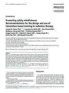
Figure 7 on the next page shows the time history of the longitudinal short period mode triggered by the canard pulse. Characteristics of this mode are observed from the time histories: short period, violent variations in angles of attack and pitch, and little or no altitude and speed change throughout the motion. Scenario 4: One Engine Out in Cruise Figure 8 on page 8 shows the time history for the engine out in mid-cruise flight. From the subsonic trim condition, engine 2 is failed 30 seconds into the flight. The pilot is asked to maintain airspeed, altitude and attitude with all available controls. The failure of the engine resulted in a large yawing moment which is immediately corrected with the use of the rudder to maintain the zero sideslip trim condition. Small aileron and canard deflections are observed, resulting from the need to maintain level attitude. It is clear from this flight that the aircraft can safely maintain its en-route flight with only one engine.
The following sections describe scenarios that were developed for the SSBJ to demonstrate the capabilities of VATES and the VT&E methodology. Vehicle behavior during cruise and takeoff is virtually evaluated with the help of autonomous simulation. Scenario 1: Trim at cruise The available version of VATES does not include a trimming routine. Instead, the “silicon pilot” is asked to maintain certain conditions with a set of controls available to him. For example, to trim the aircraft at cruise, a trimming scenario would have the pilot keep wings level with the ailerons, zero sideslip with the rudder, cruise velocity with the throttles, and altitude with longitudinal controls (canards in the SSBJ). Leaving enough time for the transients to die, trim would
Scenario 5: Takeoff To model takeoff the “silicon pilot” is asked to apply full throttle, steer the airplane on the runway centerline and lift-off 30 seconds after engine start. 6
IAS km/h 500.0
Alt m 11000.0
throttl1 % 125.0
Mach − 1.1
10600.0
420.0
0.94
100.0
10200.0
340.0
0.78
75.0
9800.0
260.0
0.62
50.0
9400.0
180.0
0.46
100.0 280 300 AoA degr 20.0
0.3
9000.0
0 20 vert sp m/s 15.0
40
60
80
100
120
140
160
180
200
220
240
260
25.0
0 20 path degr 25.0
40
60
80
100
120
140
160
180
200
220
240
260
0.0 300 mass kg 100000.0
280
5.0
15.0
15.0
80000.0
−5.0
10.0
5.0
60000.0
−15.0
5.0
−5.0
40000.0
−25.0
0.0
−15.0
−35.0
0 20 pitch degr 25.0
40
60
80
100
120
140
160
180
200
220
240
260
−5.0 280 300 canards degr 25.0
15.0
20000.0
−25.0
0 20 CD_(s) − 0.05
40
60
80
100
120
140
160
180
200
220
240
260
0.0 280 300 CL_(s) − 0.5
15.0
0.04
0.4
5.0
0.03
0.3
−5.0
−5.0
0.02
0.2
−15.0
−15.0
0.01
5.0
−25.0
0 20 bank degr 30.0
40
60
80
100
120
140
160
180
200
220
240
260
−25.0 280 300 aileronR degr 20.0
0.1
0.0
0 20 CM_pitch − 0.25
40
60
80
100
120
140
160
180
200
220
240
260
0.0 280 300 flaps degr 20.0
20.0
10.0
0.15
10.0
10.0
0.0
0.05
0.0
0.0
−10.0
−0.05
−10.0
−20.0
−0.15
−30.0 280 300 rudder degr 30.0
−0.25
−20.0
0 20 sideslip degr 25.0
40
60
80
100
120
140
160
180
200
220
240
260
−10.0 −20.0
0 20 S_shock1 m 1.0
40
60
80
100
120
140
160
180
200
220
240
260
−30.0 280 300 S_shock2 m 1.0
15.0
20.0
0.8
0.8
5.0
10.0
0.6
0.6
0.0
0.4
0.4
−10.0
0.2
−20.0 300
0.0
−5.0 −15.0 −25.0
0
20
40
60
80
100
120
140
160
180
200
220
240
260
280
0.2 0
20
40
60
80
100
120
140
160
180
200
220
240
260
0.0 300
280
Figure 6: Phugoid at subsonic cruise
IAS km/h 500.0
Alt m 11000.0
throttl1 % 125.0
Mach − 1.1
10600.0
420.0
0.94
100.0
10200.0
340.0
0.78
75.0
9800.0
260.0
0.62
50.0
9400.0
180.0
0.46
100.0 80 AoA degr 20.0
0.3
9000.0 0 vert sp m/s 15.0
20
40
60
0 path degr 25.0
20
40
60
25.0 0.0 80 mass kg 100000.0
5.0
15.0
15.0
80000.0
−5.0
10.0
5.0
60000.0
−15.0
5.0
−5.0
40000.0
−25.0
0.0
−15.0
−35.0 0 pitch degr 8.0
20
40
60
−5.0 80 canards degr 20.0
20000.0
−25.0
0 CD_(s) − 0.05
20
40
60
0.0 80 CL_(s) − 0.5
7.0
15.0
0.04
0.4
6.0
10.0
0.03
0.3
5.0
5.0
0.02
0.2
4.0
0.0
0.01
3.0 0 bank degr 30.0
20
40
60
−5.0 80 aileronR degr 20.0
0.1
0.0
0 CM_pitch − 0.25
20
40
60
0.0 80 flaps degr 20.0
20.0
10.0
0.15
10.0
10.0
0.0
0.05
0.0
0.0
−10.0
−0.05
−10.0
−20.0
−0.15
−30.0 80 rudder degr 30.0
−0.25
−20.0 0 sideslip degr 25.0
20
40
60
−10.0 −20.0
0 S_shock1 m 1.0
20
40
60
−30.0 80 S_shock2 m 1.0
15.0
20.0
0.8
0.8
5.0
10.0
0.6
0.6
0.0
0.4
0.4
−10.0
0.2
−20.0 80
0.0
−5.0 −15.0 −25.0 0
20
40
60
0.2 0
20
Figure 7: Short period at subsonic cruise
7
40
60
0.0 80
Alt m 11000.0
IAS km/h 500.0
throttl1 % 125.0
throttl2 % 125.0
10600.0
420.0
100.0
10200.0
340.0
75.0
75.0
9800.0
260.0
50.0
50.0
9400.0
180.0
25.0
100.0 200 AoA degr 20.0
0.0
9000.0 0 20 vert sp m/s 15.0
40
60
80
100
120
140
160
180
100.0
25.0
0 20 path degr 15.0
40
60
80
100
120
140
160
0.0 180 200 heading degr 10.0
5.0
15.0
10.0
5.0
−5.0
10.0
5.0
0.0
−15.0
5.0
0.0
−5.0
−25.0
0.0
−5.0
−35.0 0 20 pitch degr 20.0
40
60
80
100
120
140
160
−5.0 180 200 canards degr 25.0
−10.0
−10.0 0 L/D − 15.0
20
40
60
80
100
120
140
160
180
−15.0 200 Mach − 1.0
15.0
15.0
12.0
0.8
10.0
5.0
9.0
0.6
5.0
−5.0
6.0
0.4
0.0
−15.0
3.0
−5.0 0 20 bank degr 30.0
40
60
80
100
120
140
160
−25.0 180 200 aileronR degr 10.0
0.2
0.0
0 20 flaps degr 20.0
40
60
80
100
120
140
160
180
0.0 200 K_gear − 2.0
20.0
5.0
10.0
1.0
10.0
0.0
0.0
0.0
0.0
−5.0
−10.0
−10.0
−20.0
−10.0 −20.0 0 20 sideslip degr 10.0
40
60
80
100
120
140
160
180
−15.0 200 rudder degr 30.0
−1.0 −2.0
−30.0 0 20 g_factor − 4.0
40
60
80
100
120
140
160
180
−3.0 200 S_shock2 m 1.0
5.0
20.0
3.0
0.8
0.0
10.0
2.0
0.6
−5.0
0.0
1.0
0.4
−10.0
0.0
−10.0 −15.0 0
20
40
60
80
100 120 time, sec
140
160
180
−20.0 200
0.2
−1.0 0
20
40
60
80
100 120 time, sec
140
160
180
0.0 200
Figure 8: Engine out in en-route cruise flight
until the altitude reaches 500 ft, Flaps are deflected q at which point they are retracted to . Canards are deq flected once the rotation speed is attained and then used to maintain a climbing speed of 20 m/s. Bank and sideslip angles are maintained at zero with the use of ailerons and the rudder. The two engines are throttled back to 75% once the 500 m altitude mark was achieved. q
time histories. The phugoid period is 77.1 seconds. Averaged peak amplitudes were used to determine the damping ratio to be 0.0441. The same analysis was conducted for the short period motion based on the pitch angle and angle of attack time histories. However, the low sampling frequency coupled with the speed of motion makes it difficult to extract meaningful dynamic information. Only one oscillation is observed in the span of 2 seconds, which yields 4 data points that can be used to extract period and damping ratio information. With larger sampling frequencies it is expected that FFT techniques would yield valuable data.
Figure 9 on the next page shows the result of this simulation for the SSBJ. Rotation speed was guessed at 360 km/hr. From the shock absorber data history (S-shock1 and S-shock2) we observe that the nose wheel becomes airborne at 18.2 seconds and that the main gears are off the ground 27.7 seconds into the scenario. The indicated airspeed at the point of liftoff is 603 km/hr.
However, metrics that can be extracted from the time histories are not limited to dynamic modes. For instance from the takeoff scenario, total takeoff roll length, duration, and time to the 50 ft mark could be extracted. From the engine out scenario, recovery time, altitude loss, and control deflections necessary to sustain normal attitude could also be extracted. Furthermore, flight scenarios can be designed to match Federal Aviation Regulations (FARs) certification criteria [18]. This allows certifiability and safety issues to be quantified and examined as early as the conceptual design phase within the VT&E methodology.
EXTRACTION OF METRICS FROM SIMULATION The output of the simulation in VATES includes, in particular, time histories. Any variables used within VATES can be recorded against time or one another. From these time histories, stability and control metrics need to be extracted. In the interest of time, this study concentrated on the extraction of handling quality metrics for the phugoid and short period longitudinal modes.
DISCUSSION OF RESULTS
The time histories for vertical speed, flight path angle and angle of pitch of Figure 6 were used to extract frequency and damping ratio from the phugoid motion. Due to the low sampling frequency of the data contained in the VATES time histories (2Hz), fast Fourier transform (FFT) techniques could not be used. Instead, averaged peak to peak times were used to determine the period from the
DESIGN/SIMULATION LINK A set of computer tools were developed to link the design to the simulation environment. This allows for the automatic generation of necessary input data for flight simulation in VATES, the first step of the VT&E methodology. Successful automatic 8
Alt m 2500.0
IAS km/h 500.0
throttl1 % 125.0
throttl2 % 125.0
2000.0
400.0
100.0
1500.0
300.0
75.0
75.0
1000.0
200.0
50.0
50.0
500.0
100.0
25.0
0.0 0 vert sp m/s 15.0
20
40
60
80
0.0 100 AoA degr 20.0
100.0
25.0
0.0
0 path degr 15.0
20
40
60
80
0.0 100 heading degr 10.0
5.0
15.0
10.0
5.0
−5.0
10.0
5.0
0.0
−15.0
5.0
0.0
−5.0
−25.0
0.0
−5.0
−35.0 0 pitch degr 20.0
20
40
60
80
−5.0 100 canards degr 25.0
−10.0
−10.0 0 L/D − 15.0
20
40
60
80
−15.0 100 g_factor − 4.0
15.0
15.0
12.0
3.0
10.0
5.0
9.0
2.0
5.0
−5.0
6.0
1.0
0.0
−15.0
3.0
−5.0 0 bank degr 30.0
20
40
60
80
−25.0 100 aileronR degr 10.0
0.0
0.0
0 flaps degr 20.0
20
40
60
80
−1.0 100 K_gear − 2.0
20.0
5.0
10.0
1.0
10.0
0.0
0.0
0.0
0.0
−5.0
−10.0
−10.0
−20.0
−10.0 −20.0 0 sideslip degr 10.0
20
40
60
80
−15.0 100 rudder degr 30.0
−1.0 −2.0
−30.0 0 S_shock1 m 1.0
20
40
60
80
−3.0 100 S_shock2 m 1.0
5.0
20.0
0.8
0.8
0.0
10.0
0.6
0.6
−5.0
0.0
0.4
0.4
−10.0
0.2
−20.0 100
0.0
−10.0 −15.0 0
20
40
60
80
0.2 0
time, sec
20
40
60
80
0.0 100
time, sec
Figure 9: Normal Takeoff
obtain supersonic, or vortex lift data with HASC95. The difficulty seems to be in the paneling obtained from the paneling program. Moreover, direct applicability of the paneling program to drastically different configurations is difficult due to the fact that some of the paneling features for the SSBJ were “hard-coded” for the sake of simplicity and time. However, a complete rewrite of the paneling program in the object-oriented JAVA language is currently in progress. The object-oriented features will allow for generic paneling of any configuration, thereby extending its use to other vehicle types.
VATES input generation was obtained for the SSBJ baseline. However, the link developed here cannot yet practically be implemented within a larger design architecture where the design metrics are regressed on the design variables to establish the design relationships needed to evaluate the design space for feasibility, viability, optimum, etc . . . This is due to the fact that for a single design point (as here for the baseline SSBJ), it takes in excess of two hours to generate aerodynamic data alone. The large computational time is due to the fact that HASC95 has to be executed 8 times for a large angle of attack and Mach number sweep to generate the derivatives needed for the aerodynamic model. If this were to be repeated for 150 different designs, as is often the case with DOE/RSM methodology, 300 hours would have to be spent to arrive at the desired design relationships for one vehicle.
VT&E METHODOLOGY After obtaining model data, the second step in the VT&E methodology consists of designing appropriate flight scenarios to test and evaluate vehicle behavior accordingly and quantify needed operability design metrics. Four scenarios were designed to evaluate the dynamic behavior of the SSBJ baseline during subsonic cruise and takeoff. Because these scenario definitions are independent of the aircraft being simulated, they can be conveniently reused for other types of aircraft. Once a library of flight scenarios is created to allow for the capture of necessary metrics, it can be used to extract such metrics for any aircraft model.
One solution to such problem is to have the aerodynamic model provide total force and moment coefficients (rather than derivatives) as functions of both state and geometry to the simulation. This could be achieved, for example, with the DOE/RSM methodology. The aerodynamic model would then be made of polynomial expressions for the six coefficients as functions of contributing state and design variables. Such a model would not need to be recomputed for each design point, thereby eliminating the need for 2 hour computations every time the geometry changes slightly. Instead, computations would be made up-front and only once.
The last step in the VT&E methodology consists of extracting design metrics from the output of the simulations performed. Computer scripts were written to extract the period and damping ratios of the two longitudinal modes. This process hopefully demonstrates the ease with which metrics of interest can be extracted from simulation output. Any metric automatically extracted in this way can then be linked back to the design variables to establish
The authors also experienced difficulties when trying to 9
REFERENCES
the desired design relationships.
[1] Dimitri N. Mavris and Daniel A. DeLaurentis. A stochastic approach for aicraft affordability. ICAS, 1998.
FIDELITY The use of simulation in early phases of design and the value its output brings to the design process is limited by modeling fidelity and uncertainty. System characteristics such as aerodynamics, propulsion, and mass distribution are evaluated by computer analyses which carry uncertainty, thereby affecting the fidelity of simulation models and of the simulation itself. This study was not intended as an accurate demonstration of the true flying characteristics of the SSBJ. Rather, the aim was to demonstrate and implement the methodology by which flight simulation can be used in conceptual design.
[2] Dimitri N. Mavris and Elena Garcia. Affordability assessment for a subsonic transport. ISPA/SCEA, 1999. [3] AGARD conf. proceedings. Flight Simulation — Where are the Challenges?, number AGARD-CP577, Braunschweig, Germany, 1995. [4] D. N. Mavris, D. A. DeLaurentis, Oliver Bandte, and Mark A. Hale. A stochastic approach to multidisciplinary aircraft analysis and design. AIAA, 1998.
Assessing model fidelity and uncertainty and its effect on the simulation is understood as being the next step in the process of successfully implementing simulation in conceptual design. Capturing and quantifying such uncertainties is necessary for the assessment of risk in design decisions based on simulation. DeLaurentis has described the use of statistical analyses to model uncertainty within early handling qualities evaluation based on parametric metamodels [6] and in the generation of dynamic model [19]. Applying these methods to capture each source of quantifiable uncertainty related to simulation model data should the basis for future work on the VT&E methodology.
[5] Dimitri N. Mavris, Oliver Bandte, and Daniel P. Schrage. Application of probabilistic methods for the determination of an economically robust hsct configuration. AIAA, 1996. [6] Dimitri N. Mavris, Daniel A. DeLaurentis, and Danielle S. Soban. Probabilistic assessment of handling qualities characteristics in preliminary aircraft design. In 36th Aerospace Sciences Meeting & Exhibit, number AIAA 98-0492. [7] Dimitri N. Mavris and Michelle R. Kirby. Preliminary assessment of the economic viability of a family of very large transport configurations. AIAA, 1996.
CONCLUSIONS A direct link between the design geometry and the simulation environment was developed. This link comprises an aerodynamic model data generator based on the HASC95 program and various data formatting programs to generate simulation input from a vehicle geometry description file. The Virtual Autonomous Testing and Evaluation Simulator (VATES) was used as the main simulation tool within the Virtual Testing & Evaluation methodology. It allowed for autonomous simulation of the vehicle based on a set of predefined flight scenarios, a core attribute of the methodology.
[8] Arnie McCullers. Flight OPtimization System. NASA Langley. version 5.94. [9] Ivan Y. Burdun and Oleg M. Parfentyev. Analysis of aerobatic flight safety using autonomous modeling and simulation. In Advances in Aviation Safety Conference and Exposition, number 00ASC-12, Daytona Beach, Florida, April 11-13 2000. SAE. [10] Ivan Y. Burdun and Dimitri N. Mavris. A technique for testing and evaluation of aircraft flight performance during early design phases. In World Aviation Congress, number 975541. AIAA/SAE, October 1997.
It was demonstrated that key stability and control metrics can be extracted from the output of such autonomous simulations thereby extending the set of metrics from readily available performance and economic metrics.
[11] I. Y. Burdun. An AI situational pilot model for realtime applications. In 20th Congress of the International Council of the Aeronautical Sciences, volume I, pages 210–237, Sorrento, Italy, 8-13 September 1996.
Overall the VT&E methodology holds many promises. As the link between design and simulation evolves and better usability is gained, total virtual conceptual design based on simulation will provide more and better design knowledge to the designer. This will, in turn, translate into substantial amounts of cost and design cycle time savings, as is predicted by the paradigm shift.
[12] J. M. Rolfe and K. J. Staples. Flight Simulation. Cambridge Aerospace Series. Cambridge University Press, 1986. [13] Alan E. Albright, Charles J. Dixon, and Martin C. Hegedus. Modification and validation of conceptual design aerodynamic prediction method HASC95 with VTXCHN. Technical report, NASA Contract Report 4712, 1996. 10
[14] John E. Williams. USAF Stability and Control Digital Datcom. USAF, 1979. [15] Luis R. Miranda, Robert D. Elliot, and William M. Baker. A Generalized Vortex Lattice Method for Subsonic and Supersonic flow applications. NASA Contract Report 2865, 1977. [16] H. W. Carlson, J. Chu, L. P. Ozoroski, and L. A. McCullers. Guide to AERO2S and WINGDES computer codes for prediction and minimization of drag due to lift. NASA-TP-3637, 1997. [17] Boeing. Boeing Drag Analysis Program, BDAP. [18] Ivan Y. Burdun, Daniel A. DeLaurentis, and Dimitri N. Mavris. Modeling and simulation of airworthiness requirements for an hsct prototype in early design. 1998. AIAA-98-4936. [19] Daniel A. DeLaurentis, Dimitri N. Mavris, Anthony J. Calise, and Daniel P. Schrage. Generating dynamic models including uncertainty for use in aircraft conceptual design. In AIAA Atmospheric Flight Mechanics Conference, number AIAA 97-3590.
11