Structural engineering is the design of building ... structural simulation involves the analysis of "load ..... The Weaire Phelan foam structure consists of 22000.
Ninth International IBPSA Conference Montréal, Canada August 15-18, 2005
THE USE OF ADVANCED COMPUTER SIMULATION IN STRUCTURAL DESIGN Caroline J Field1, Andrew Mole1 and Mark Arkinstall2 1 Arup, San Francisco, USA 2 Arup, Sydney, Australia
Performance Based Approach
ABSTRACT This paper covers the innovative use of advanced numerical simulation in the field of structural engineering. It begins with a brief review of current standard practice and then discusses the latest more advanced technologies and approaches that are available. The practical benefits of using advanced simulation as an integral part of the design process are illustrated through a range of international project case studies.
INTRODUCTION Current Structural Design Practice Structural engineering is the design of building elements to resist a set of environmental building loads. Some of these loads are very straightforward – such as the dead weight of the building and the weight of potential occupants, fitout, machinery and furniture. These are static loads. Other types of load depend on location and are subject to statistical interpretation of their frequency and size, such as wind or typhoon loading, earthquake and wave loading. Others are unpredictable such as blast and impact loading. These loads are dynamic and time varying in nature.
Performance based engineering is establishing a set of performance criteria that is acceptable for the client for prescribed load scenarios and then quantifying the building performance through appropriate methods and adjusting the design where necessary. Simulation plays an important role in quantifying the performance and is a necessary tool for enabling this type of approach. This approach is gaining ground in current practice and has been adopted by some modern guidelines. In the United States, publications sponsored by the Applied Technology Council (ATC) and the Federal Emergency Management Agency (FEMA) discuss and provide guidance on the use of increasingly sophisticated analysis techniques within a performance based design approach. Standard Analytical Methods Standard practice in structural engineering is a moving target as in all technical fields, but with regard to mathematical modeling is characterized by the following: •
One-dimensional (and increasingly twodimensional) representation of structural elements using finite element formulation
•
Matrix representation of the stiffness of a twoor three-dimensional structure or sub-assembly
•
Linear analysis (implicit analysis) by means of stiffness matrix inversion to generate the static stress state in the structural model resulting from static loads or imposed displacements
Building Code Approach Structural design is prescribed by a whole range of building codes, depending on location, building type and loading. Building codes should be viewed as a minimum design standard. They are generally empirical in nature and are an attempt to provide a set of simplified design rules that cover the majority of buildings. The fact that these rules have to be applicable to a very wide range of buildings, means that for some buildings the design can be very conservative and for others possible unconservative. Often, buildings do not fit comfortably within these rules and certainly, if one wants to take advantage of new technologies and developments in the design, these will not be covered by the code.
Since the models are linear elastic, the results from any two loading conditions calculated separately can be combined to provide the results that would be obtained from analyzing the model stress state for the combined loads. In cases where dynamic characteristics are significant, for example for machine vibration or seismic analysis, linear elastic modal analyses are performed. This is relatively unusual in terms of global structural engineering, but is becoming
- 303 -
standard practice in places where seismic loads are critical in design. The methods outlined above are restrictive in so far as they limit the analyst-designer to design conditions that can reasonably be approximated by linear formulations, and these are the approaches that are codified (e.g. in the Uniform Building Code or its successor the International Building Code). However, for situations where the structure responds outside of the linear elastic range of its materials, for example, seismic, blast and impact scenarios, these approaches can provide only an approximate indication of the building’s peformance by introducing “factors” to account for these nonlinearities. In these situations, advanced simulation, which incorporates the effects of geometric and material nonlinearities, provides a far superior representation of the actual performance. This must be informed by a fundamental understanding of the "first principles" that underlie the code and structural behavior in general.
ROLE OF ADVANCED SIMULATION
Applications Advanced structural simulation would typically be used to address the following situations: •
Unusual buildings not defined by the code
•
Complex problems not addressed by the code
•
Cases where the code is too conservative
•
Virtual Testing & Prototyping
•
Verifying Innovative Design Concepts
•
Forensic Engineering
•
Value Engineering (design optimization)
Value The benefits to be gained when appropriately utilzing advanced simulation include the following: •
Creative and innovative design solutions can be virtually tested and developed during the design phase •
Definition In the context of structural engineering, advanced simulation is the application of mathematical modeling to problems that are complex and are at a higher level than standard practice. In this paper, "advanced simulation" will be used to refer to non-linear dynamic analysis of multi-degreeof-freedom systems. "Advanced simulation" permits a much wider consideration of building types and conditions than can be reliably be designed using standard practice. Analysis in standard practice is characterized by the definition of static load conditions (typically called "load cases") which are summed. However, advanced structural simulation involves the analysis of "load scenarios", which must be defined to represent conditions that can reasonably be considered to occur and are typically time varying. Thus multiple scenarios will be run for every structural model.
Improve Performance The building performance can be accurately quantified and then optimized to improve the performance under the load scenarios
•
Produce Cost Savings By adopting a performance based approach and utilizing advanced simulation the conservatisms inherent in a simple code approach can often be reduced to provide significant cost savings
•
Manage Risk The client is able to consider the risk and cost associated with various design solutions because he/she better understands the consequences of each load scenario because it has been quantified through “virtual testing”of each design option
•
Increase Sustainability The ability to accurately predict building behavior coupled with the ability to explore more innovative design solutions often leads to a more economic solution that more efficiently and effectively meets the design criteria, thereby achieving a more sustainable design solution
Tools The analyst-designer has increasingly greater choice of tools for advanced simulation (based on implicit and explicit solvers or a combination). In many cases these are also "multi-physics" - able to perform "coupled" analyses - for example, coupling thermal analysis with structural analysis to model the effect of fire on structural steel frames.
Enable Creativity
•
These packages typically have powerful graphical user interfaces available to speed up the process of modeling and to aid the interpretation of results.
- 304 -
Enhances Communication Simulation can be a very compelling and invaluable visualization tool if using good software. It facilitates a dialogue with your client and makes it easier for the engineer to communicate complex concepts in a simple way. In the same way it can facilitate a creative dialogue between the design team.
Getting in early One of the biggest challenges with structural simulation is the difficulty of getting involved from the project conception and being able to utilize simulation as a creative part of the design process and not just as a verification tool.
Figure 1 Benefit of early use of simulation – from Stefan Thomke “Experimentation Matters” There is good evidence (Thomke, 2003) to suggest that the ability of simulation to allow for earlier and faster design iterations to occur greatly reduces problems later on in the design process, thereby reducing the length of the overall development process and therefore the cost too. Couple this with learning from previous projects, as illustrated in Figure 1, and you have a much better chance of reducing the total number of problems on a project.
CASE STUDIES The following five case studies give a diverse illustration of the practical benefits and value gained by using advanced simulation as an integral part of the design process. Maison Hermes, Tokyo This prestigious new building is located on a narrow site in Tokyo’s central Ginza district. The controlling scenario for structural design is its performance in seismic events. The architect envisioned a 13-storey glass structure appearing transparent from the street, which would mean pulling all of the structure away from that façade as much as possible. Thus only a small zone at the rear of the building would be available for the heavy structural elements that are required to resist horizontal earthquake actions. Conventional steel frame construction was found to be prohibitively heavy and expensive. Instead a radical change to the design philosophy was proposed. The solution was to
permit the rear columns of the seismic frame to lift off their foundations when the column experienced tension. This innovative ‘stepping column’ would enable the building to ‘rock’ to a limited degree under strong earthquake actions. This behavior would reduce seismic forces in the building and hence cut steelwork and foundation costs. The lifting of the columns was controlled by visco-elastic dampers, which would provide preferential energydissipation over hysteretic deformation of the frames, which is the standard approach in building design. As a result less structural damage would occur in any seismic event. As would be expected the performance of this system cannot be satisfactorily predicted using linear elastic analysis and it clearly falls outside the normal bounds of building codes. As a result non-linear analysis was used throughout the design process, explicitly simulating the performance of the structure to various earthquake scenarios. Such studies were performed initially to evaluate the system as a concept, then subsequently to develop the design and to assess proposed changes and finally to report the performance of the system as designed. These studies showed that there would be negligible damage under even the strongest seismic events, and that the performance was superior to that of a conventional scheme containing three times the quantity of steel. Three different types of models were used through the design process. Initial studies (non-linear dynamic) were performed using elastic beam elements and non-linear gap elements and viscoelastic dampers (Kelvin formulation). Thus the nonlinear was assumed to be limited to the performance of the dampers and the gap element. A solid element model of the column base was created to look at impact stresses. Finally a model of a single bay was created to look at the performance of the beams in detail. They were modeled explicitly using shell elements. This showed that in the extreme earthquake scenario, steel yield was limited to the spandrels. The design was presented to a peer review committee made up of professors and industry experts as required by Japanese Building Law for buildings that do not fit the standard requirements. It received approval unusually quickly thanks to the way in which the advanced numerical simulation was able to quantify the behavior of this innovative system. In summary, the advanced simulation approach made it possible •
to propose an innovative structural solution to deliver the architect's vision of a structure-free façade, which would otherwise have been impossible
•
to gain building approval quickly, saving on project schedule
- 305 -
•
to save $1 million in foundation costs
•
reduce amount of steel by factor of 3
•
to deliver performance
quantifiably
better
seismic
match between the comparison of displacement at a control node on the frame between test and simulation. The sequence of yield in the simulation closely match that observed during the test. An example of this is shown in Figure 5 where the plastic behavior at the column base is compared.
Figure 3(a)
3(b) FE Sim
Displacem ent Com parison Displacement (mm)
Test
Figure 2(a) Maison Hermes (b) Finite Element Model
80 60 40 20 0 -20 0
10
20
30
-40 -60
Unbonded Brace
-80 -100
A good example of enabling innovative solutions and virtual testing is the implementation of the Unbonded Brace (UB) in to the US market. The UB was conceived in Japan and offers improved performance characteristics over other seismic resisting braces, because of its resistance to global and local buckling (Wada et al). It comprises a core of high ductility steel within a concrete matrix confined by a steel tube. The brace exhibits nearly identical properties in tension and compression and has the ability to undergo numerous cycles of inelastic deformations without degradation or fracture. Arup used this system on a number of Japanese projects and recognized its potential for use in California.
Load Step
Figure 4 Comparison of control node displacement Subsequently, this virtual test procedure was used on a hospital project to successfully prove the seismic performance of the unbonded brace and associated frame elements to the Office of Statewide Health & Planning (OSHPD) officials in California. The use of simulation should not remove the need for real testing, as it is important to calibrate simulation against reality, but it can be used effectively to inform real testing and reduce the number and cost of real tests, as it did in this case.
As this was a new system in the United States, rigorous research, testing and verification was required and computer simulation played an important part in this process, along with real testing. In 2002, a full-scale pseudo dynamic test of an Unbonded braced frame was carried out at UC Berkeley, CA (Mahin et al, 2004). The test was simulated using the implicit solver of LS-Dyna with excellent results (Field, 2003). Figure 3(a) shows the test set up and Figure 3(b) shows the finite element model. The frame was modeled using shell elements and a non-linear steel material model. A prescribed cyclic displacement was applied to the test frame and the finite element frame. Figure 4 shows a good
- 306 -
Figure 5 Comparison of plastic deformation
Disney Museum This project provided an opportunity to utilize simulation during the concept phase of the project, in order to determine whether this existing building was a viable location for the new museum to honor Walt Disney.
earthquake time histories to the building model and then examining the resulting deformations. One of this earthquake time histories is shown in Figure 8. These showed that the building would have significant damage during a design earthquake and that retrofitting would be required to satisfy the life safety design criteria.
The purpose of this investigation was to understand, as accurately as possible, the real capacity of the existing building to resist earthquakes and to get an indication of the level of retrofit that will be required to bring it up to a modern life safety standard. This study compared a performance based simulation to code methods, to gauge the benefits of this type of approach for the project. A detailed computer model of the existing building (incorporating the proposed architectural modifications) was built and is shown in Figure 6. The model can represent the non-linear behavior of masonry and other materials (e.g. cracking of masonry or concrete, sliding of masonry bed joints, rocking of piers) when they experience extreme loading such as occurs in a large earthquake. The nonlinear shear model for masonry is shown in Figure 7.
Figure 8 Earthquake time history record The model was then used to develop two potential retrofit options – one comprising the addition of new shotcrete walls and the other a mainly masonry reinforcement scheme. By iterating the analysis it was possible to come up with two retrofit schemes that minimize the amount of intervention required and maximize the retention of the current aesthetic. When compared to a standard code design approach (UBC97 and linear static provisions of FEMA356) the retrofit required is considerably less. This illustrates that code approaches are unnecessarily conservative for this building and a seismic assessment using advanced simulation is very effective in reducing and optimizing the retrofit required. This resulted in a $0.5m (30%) cost saving for this project and allowed a beautiful, existing building to be reused making it a more sustainable option.
Figure 6 Disney Museum Finite Element Model
Shear Stress
By quantifying the performance of this building more accurately the earthquake risk was quantified, which gave the client the confidence to proceed with the choice of this building for their new museum.
MIT Brain & Cognitive Science Project
Shear Strain
Figure 7 Material model for shear behavior of masonry The seismic performance of the building was simulated by applying a number of site specific
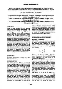
This building will contain laboratories to conduct various experiments using precision equipment. The site is surrounded by potential vibration the worse of which is a surface railway on which heavy freight vehicles cross the site a few times a day, which can be clearly seen in Figure 9.
- 307 -
An arrangement of masses, springs and dampers is used to simulate a locomotive and a series of masses is used to represent the freight car axles moving along the rails. Sprung Mass
Figure 9 MIT Brain & Cognitive Science Project
Train wheel with surface roughness
This study made extensive use of numerical simulation to predict the effect of different foundation types on the vibration entering the building and to compare mitigation options. Measured soil properties, current building geometry and measured railway data were used.
UN - sprung Mass travels along track Track with surface roughness
The basic model shown in Figure 10 below represents a large volume of soil at the site approximately 165ft long by 165ft wide by 130ft deep. The model was created and analysed in the finite element program LS-DYNA.
Figure 11 Train/Track representation A roughness profile is applied to each rail, as shown in Figure 12(a). The wheel roughness assumed for the study is shown in Figure 12(b).
Wheel Roughness
T rack Roughness - T rack 1
As this model represents a finite section of ground at the site, non reflecting boundaries were used at the sides and base of the soil block to allow the stress waves to pass out of the model without spurious reflections at the cut surfaces.
12
12
10
10
8
8 6
6
4
Profile (mm)
4
Profile (mm)
The block of soil is made up of a series of different layers representing the strata present at the site. Their individual properties and thicknesses were determined from seismic cone penetration tests at the site.
Sprung Mass Suspension (Damper and Spring)
2 0 -2
2 0 -2
-4
-4
-6
-6 -8
-8
-10
-10
-12
-12 0
50
100
150
200
250
300
350
400
450
500
Chainage (m)
Figure 12(a )
0
3
6
9
12
15
18
Chainage (m)
12(b)
As the train model moves along the track, vertical relative movements between the wheel center and the rail centerline are induced by the rough wheels moving over the rough rails. The inertia forces generated by these movements are the source of the vibration. The analytical process is thus a direct simulation of the processes that cause the vibrations in practice. The finite element model was calibrated against the measured data. It is always important to measure actual beahvior where possible to imporve the accuracy of the simulation models.
Figure 10 Finite Element Simulation Model The railway track is modeled as a series of beam elements, making up a track approximately 1600ft long sitting on a thin layer of ballast material. The model of the train for this phase of the study represents typical vehicles using the track at this site.
A cost benefit assessment of each option was produced so that the client was able to make an informed decision based on the risk and cost of each scheme.
- 308 -
Beijing Aquatic Center (“The Water Cube”) The Beijing Aquatic Centre (Figure 13) is an excellent example of the use of optimization within structural analysis. It consists of a 3-dimensional cellular structure following the tiling of WeairePhelan foam. The Weaire Phelan foam is currently the most efficient cellular tiling of space to minimize the surface area of the cells and is completely mathematically derived. This gives the feeling of an organic structure that is apparently random due to the cutting planes of the structure, but is actually completely regular.
Figure 13 Beijing Aquatic Center Architects render The Weaire Phelan foam structure consists of 22000 beams. The structure has no triangulation and therefore is a 3 dimensional vierendeel. Changing any one member size changes the distribution of the moments and forces in the surrounding members. The challenge is therefore how to design such a structure so that all members satisfy the strength, serviceability, and seismic ductility requirements for the 200 load combinations all at once, while achieving an optimized structural solution. Initially, gradient based optimization methods were considered, however, with 22000 variables and 50 million design constraints to be satisfied that was not feasible. The solution was to adopt a constraint satisfaction method of iterative design.
The optimized three group member sets were then fed into the global constraint satisfaction optimization routines. Initially all members were set to the smallest allowable member size for their group. An analysis was then performed and each member was checked for constraint compliance in the form of Chinese design code utilization. If a member was found to be overutilized its members size was increased by one size in is group member set. If a member suddenly became underutilized its size was reduced by one size in the group member set. It was very important to limit the size movement to only one step per iteration, due to the sensitivity of the 3d vierendeel to force redistribution when member size changed. Each member in a group could be any of the member sizes allocated for that group. This allowed for minimization of mass, a critical factor in long span roof structures. However, this meant that connections became complex, as every connection could be different. A complex set of rules was derived for the design of the connection sizes, and plate thicknesses as a result. The optimization converged quite rapidly in only 25 or so iterations, but this is really a function of the number of allowable member sizes in each group. In all, only 37 different member sizes make up the 22000 beam structure. The optimized structure is shown in Figure 14. The final step of the process was complete automation of tender documentation. The optimization process created an input data file which could be read into purpose written CAD scripts developed for the Beijing Aquatic Centre project. Full 3d solid CAD tender models and 2d drawings with beam mark annotation were able to be generated in less than 1 hour. This combined with the automated constraint satisfaction optimization meant that an entire design cycle from start of analysis and design to completion of tender drawings took 24 hours.
The superstructure consisted of three main types of members; surface members, edge members and internal members. The members were of different section types. Surface members ranged from 450x300 (18x12”) rectangular hollow section (RHS) to 180x300 (7x12”) RHS. Edge members were 300x300 (12x12”) RHS and internal members ranged from 200 (8”) circular hollow section (CHS) to 600 (24”) CHS. Each of the three groups of members was given a subset of allowable section sizes and plate thicknesses, ensuring compactness and ductile seismic behavior well into the plastic loading range. This selection of members sizes also involved optimization to pick the best distribution of group member sizes by simulated annealing techniques.
Figure 14 Beijing Aquatic Center optimized structure All automation and scripting for structural design and CAD documentation was developed by Arup specifically for the project, but in a way that made them general enough to be used for future projects.
- 309 -
Since the completion of Beijing Aquatic Centre the tools have been employed on several other projects in China, including the Beijing Olympic main stadium, and the new Beijing airport. The integration of simulation, optimization and CAD streamlined the design process and enabled this complex building to be designed efficiently and effectively.
through reducing code conservatisms and iterating and optimizing design solutions. Our industry should continue to push forward by transferring technology from other professions and should endeavor to work more harmoniously together towards a global building model that can be used by all parties including the contractor to design and build our buildings in a more efficient manner.
FUTURE TRENDS Analysis Farms
REFERENCES
Computing power continues to increase year by year, and will continue at least into the next decade. Grid computing looks likely to become more common, using the combined spare computing power in an office to run analyses. In addition, computing power as a commodity already exists in the form of "Render Farms" for the computer animation industry, and this may also be used by the construction industry.
Applied Technology Council. 1996. Seismic evaluation and retrofit of concrete buildings.
Optimization The ability to run more and bigger analyses will encourage the development of optimization tools for structures as well as lead to the requirement to perform simulations of extreme loading scenarios using non-linear software. Additionally, advances in software that take advantage of increased computing power will make multi-physics analyses more common. Visualization The development of visualization is driven by the computer graphics industry and is made possible by increases in available computing power. This will trickle across into the construction industry, possibly via other engineering fields. Interoperability
Federal Emergency Management Agency. 2000. Prestandard and commentary for the seismic rehabilitation of buildings. Field, C., 2003. Simulation of full-scale seismicresistant structural frame tests using LS-DYNA 960 Implicit Solver, LSDYNA European Conference. International Conference of Building Officials. 1997. Uniform Building Code. Mahin, S., Uriz, P., Aiken, I., Field, C., Ko, E., 2004. Seismic performance of buckling restrained braced frame systems, 13WCEE, Vancouver. Thomke, S. 2003. Experimentation Matters, Harvard Business School Press Wada, A., Saeki, E., Takeuchi, T., and Watanabe, A., c. 1998, "Development of Unbonded Brace," Nippon Steel's Unbonded Braces (promotional document), pp. 1-16, Nippon Steel Corporation Building Construction and Urban Development Division, Tokyo, Japan.
The transfer of information and building models between disciplines is something that will increase towards the goal of a global virtual building model which incorporates all of the information necessary to construct the building. These techniques are currently being adopted by computer-aided engineering packages.
CONCLUSION The use of advanced simulation tools is increasing in building engineering as technologies improve and clients demand more. The case studies have shown the benefits that can be gained from the use of advanced simulation in structural design. In particular, the reduction in risk associated with more accurate quantification of structural performance and the potential cost benefits
- 310 -