San Jose, CA 95134-1706. USA http://www.cisco.com. Tel: 408 526-4000. 800
553-NETS (6387) ..... Configuring Global Application Acceleration and
Optimization 14-10. CHAPTER 15 ..... Jcommon 1.2, Jfreechart 1.0.1. • The Cisco
..... Help button for providing context-sensitive help and a PDF version of the ANM
user guide.
User Guide for the Cisco Application Networking Manager 4.2 January 2011
Americas Headquarters Cisco Systems, Inc. 170 West Tasman Drive San Jose, CA 95134-1706 USA http://www.cisco.com Tel: 408 526-4000 800 553-NETS (6387) Fax: 408 527-0883
Customer Order Number: Text Part Number: OL-23969-01
THE SPECIFICATIONS AND INFORMATION REGARDING THE PRODUCTS IN THIS MANUAL ARE SUBJECT TO CHANGE WITHOUT NOTICE. ALL STATEMENTS, INFORMATION, AND RECOMMENDATIONS IN THIS MANUAL ARE BELIEVED TO BE ACCURATE BUT ARE PRESENTED WITHOUT WARRANTY OF ANY KIND, EXPRESS OR IMPLIED. USERS MUST TAKE FULL RESPONSIBILITY FOR THEIR APPLICATION OF ANY PRODUCTS. THE SOFTWARE LICENSE AND LIMITED WARRANTY FOR THE ACCOMPANYING PRODUCT ARE SET FORTH IN THE INFORMATION PACKET THAT SHIPPED WITH THE PRODUCT AND ARE INCORPORATED HEREIN BY THIS REFERENCE. IF YOU ARE UNABLE TO LOCATE THE SOFTWARE LICENSE OR LIMITED WARRANTY, CONTACT YOUR CISCO REPRESENTATIVE FOR A COPY. The Cisco implementation of TCP header compression is an adaptation of a program developed by the University of California, Berkeley (UCB) as part of UCB’s public domain version of the UNIX operating system. All rights reserved. Copyright © 1981, Regents of the University of California. NOTWITHSTANDING ANY OTHER WARRANTY HEREIN, ALL DOCUMENT FILES AND SOFTWARE OF THESE SUPPLIERS ARE PROVIDED “AS IS” WITH ALL FAULTS. CISCO AND THE ABOVE-NAMED SUPPLIERS DISCLAIM ALL WARRANTIES, EXPRESSED OR IMPLIED, INCLUDING, WITHOUT LIMITATION, THOSE OF MERCHANTABILITY, FITNESS FOR A PARTICULAR PURPOSE AND NONINFRINGEMENT OR ARISING FROM A COURSE OF DEALING, USAGE, OR TRADE PRACTICE. IN NO EVENT SHALL CISCO OR ITS SUPPLIERS BE LIABLE FOR ANY INDIRECT, SPECIAL, CONSEQUENTIAL, OR INCIDENTAL DAMAGES, INCLUDING, WITHOUT LIMITATION, LOST PROFITS OR LOSS OR DAMAGE TO DATA ARISING OUT OF THE USE OR INABILITY TO USE THIS MANUAL, EVEN IF CISCO OR ITS SUPPLIERS HAVE BEEN ADVISED OF THE POSSIBILITY OF SUCH DAMAGES. Cisco and the Cisco Logo are trademarks of Cisco Systems, Inc. and/or its affiliates in the U.S. and other countries. A listing of Cisco's trademarks can be found at www.cisco.com/go/trademarks. Third party trademarks mentioned are the property of their respective owners. The use of the word partner does not imply a partnership relationship between Cisco and any other company. (1005R) Any Internet Protocol (IP) addresses used in this document are not intended to be actual addresses. Any examples, command display output, and figures included in the document are shown for illustrative purposes only. Any use of actual IP addresses in illustrative content is unintentional and coincidental.
User Guide for the Cisco Application Networking Manager 4.2 © 2011 Cisco Systems, Inc. All rights reserved.
C O N T E N T S Preface
ix
Audience
ix
Organization
ix
Conventions
xi
Open-Source Software Included in the Cisco Application Networking Manager Obtaining Documentation and Submitting a Service Request
CHAPTER
1
Overview
1-1
Logging In To the Cisco Application Networking Manager Changing Your Account Password ANM Licenses
Using Homepage
1-5
2-1
Customizing the Default ANM Page 3
1-14
2-1
Information About Hompage
CHAPTER
1-3
1-4
ANM Interface Components 1-5 ANM Windows and Menus 1-7 ANM Buttons 1-9 Table Conventions 1-11 Filtering Entries 1-12 Customizing Tables 1-12 Using the Advanced Editing Option ANM Screen Conventions 1-15 2
xii
1-1
ANM Overview
CHAPTER
xi
Using ANM Guided Setup
3-1
Information About Guided Setup Guidelines and Limitations Using Import Devices
2-4
3-1
3-3
3-3
Using ACE Hardware Setup
3-4
Using Virtual Context Setup
3-9
Using Application Setup 3-11 ACE Network Topology Overview
3-11 User Guide for the Cisco Application Networking Manager 4.2
OL-23969-01
iii
Contents
Using Application Setup
CHAPTER
4
3-12
Importing and Managing Devices
4-1
Information About Device Management Information About Importing Devices
4-2 4-3
Preparing Devices for Import 4-4 Enabling SSH or Telnet Access on Catalyst 6500 Series Switches and Cisco 7600 Series Routers Enabling SSH Access and the HTTPS Interface on the ACE Module and Appliance 4-6 Enabling SNMP Polling from ANM 4-7 ANM Requirements for ACE High Availability 4-7
4-5
Importing Network Devices into ANM 4-9 Importing Cisco IOS Host Chassis and Chassis Modules 4-10 Importing Cisco IOS Devices with Installed Modules 4-10 Importing ACE Modules after the Host Chassis has been Imported 4-14 Importing CSM Devices after the Host Chassis has been Imported 4-18 Importing VSS 1440 Devices after the Host Chassis has been Imported 4-19 Importing ACE Appliances 4-19 Importing CSS Devices 4-20 Importing GSS Devices 4-21 Importing VMware vCenter Servers 4-23 Enabling a Setup Syslog for Autosync for Use With an ACE 4-25 Discovering Large Numbers of Devices Using IP Discovery Preparing Devices for IP Discovery 4-26 Configuring Device Access Credentials 4-27 Modifying Credential Pools 4-28 Running IP Discovery to Identify Devices 4-29 Monitoring IP Discovery Status 4-31
4-25
Configuring Devices 4-32 Configuring Device System Attributes 4-32 Configuring CSM Primary Attributes 4-32 Configuring CSS Primary Attributes 4-33 Configuring GSS Primary Attributes 4-34 Configuring Catalyst 6500 VSS 1440 Primary Attributes 4-36 Configuring Catalyst 6500 Series Chassis and Cisco 7600 Series Router Primary Attributes 4-36 Configuring Catalyst 6500 Series Chassis, Catalyst 6500 Virtual Switching System 1440 Devices, and Cisco 7600 Series Routers Static Routes 4-37 Configuring VMware vCenter Server Primary Attributes 4-39 Configuring Catalyst 6500 Series Chassis or Cisco 7600 Series Router Interfaces 4-39 Displaying Chassis Interfaces and Configuring High-Level Interface Attributes 4-40 User Guide for the Cisco Application Networking Manager 4.2
iv
OL-23969-01
Contents
Configuring Access Ports 4-41 Configuring Trunk Ports 4-42 Configuring Switch Virtual Interfaces 4-43 Configuring Routed Ports 4-44 Managing Catalyst 6500 Series Chassis or Cisco 7600 Series Router VLANs Adding Device VLANs 4-46 Displaying All Device VLANs 4-47 Configuring Device Layer 2 VLANs 4-48 Configuring Device Layer 3 VLANs 4-49 Modifying Device VLANs 4-49 Creating VLAN Groups 4-50 Configuring ACE Module and Appliance Role-Based Access Controls Configuring Device RBAC Users 4-51 Guidelines for Managing Users 4-51 Displaying a List of Device Users 4-52 Configuring Device User Accounts 4-52 Modifying Device User Accounts 4-53 Deleting Device User Accounts 4-54 Configuring Device RBAC Roles 4-54 Guidelines for Managing User Roles 4-55 Role Mapping in Device RBAC 4-55 Configuring Device User Roles 4-56 Modifying Device User Roles 4-58 Deleting Device User Roles 4-58 Adding, Editing, or Deleting Rules 4-59 Configuring Device RBAC Domains 4-59 Guidelines for Managing Domains 4-60 Displaying Domains for a Device 4-60 Configuring Device Domains 4-61 Modifying Device Domains 4-63 Deleting Device Domains 4-63 Managing Devices 4-64 Synchronizing Device Configurations 4-64 Synchronizing Chassis Configurations 4-65 Synchronizing Module Configurations 4-65 Mapping Real Servers to VMware Virtual Machines 4-66 Instructing ANM to Recognize an ACE Module Software Upgrade Configuring User-Defined Groups 4-70 Adding a User-Defined Group 4-70 Modifying a User-Defined Group 4-71
4-46
4-51
4-69
User Guide for the Cisco Application Networking Manager 4.2 OL-23969-01
v
Contents
Duplicating a User-Defined Group 4-72 Deleting a User-Defined Group 4-73 Updating Device Passwords 4-74 Changing ACE Module Passwords 4-75 Restarting Device Polling 4-76 Displaying All Devices 4-77 Displaying Modules by Chassis 4-78 Removing Modules from the ANM Database 4-79 Replacing an ACE Module Managed by ANM 4-80 Using the Preferred Method to Replace an ACE Module Using the Alternate Method to Replace an ACE Module
CHAPTER
5
Configuring Virtual Contexts
4-82
5-1
Information About Virtual Contexts Creating Virtual Contexts
4-80
5-2
5-2
Configuring Virtual Contexts
5-7
Configuring Virtual Context System Attributes
5-12
Configuring Virtual Context Primary Attributes
5-12
Configuring Virtual Context Syslog Settings 5-17 Configuring Syslog Log Hosts 5-21 Configuring Syslog Log Messages 5-22 Configuring Syslog Log Rate Limits 5-24 Configuring SNMP for Virtual Contexts 5-25 Configuring Basic SNMP Attributes 5-25 Configuring SNMPv2c Communities 5-26 Configuring SNMPv3 Users 5-27 Configuring SNMP Trap Destination Hosts 5-30 Configuring SNMP Notification 5-31 Applying a Policy Map Globally to All VLAN Interfaces Managing ACE Licenses 5-34 Viewing ACE Licenses 5-34 Installing ACE Licenses 5-35 Uninstalling ACE Licenses 5-37 Updating ACE Licenses 5-38 Displaying the File Contents of a License
5-33
5-40
Using Resource Classes 5-41 Global and Local Resource Classes 5-42 Resource Allocation Constraints 5-42
User Guide for the Cisco Application Networking Manager 4.2
vi
OL-23969-01
Contents
Using Global Resource Classes 5-44 Configuring Global Resource Classes 5-44 Deploying Global Resource Classes 5-46 Auditing Resource Classes 5-47 Modifying Global Resource Classes 5-48 Deleting Global Resource Classes 5-49 Using Local Resource Classes 5-49 Configuring Local Resource Classes 5-50 Deleting Local Resource Classes 5-51 Displaying Local Resource Class Use on Virtual Contexts Using the Configuration Checkpoint and Rollback Service Creating a Configuration Checkpoint 5-53 Deleting a Configuration Checkpoint 5-54 Rolling Back a Running Configuration 5-54 Displaying Checkpoint Information 5-54
5-52
5-52
Performing Device Backup and Restore Functions 5-56 Backing Up Device Configuration and Dependencies 5-59 Restoring Device Configuration and Dependencies 5-62 Performing Global Device Backup and Copy Functions 5-64 Backing Up Multiple Device Configuration and SSL Files 5-65 Associating a Global Backup Schedule with a Device 5-67 Managing Global Backup Schedules 5-69 Creating a Backup Schedule 5-69 Updating an Existing Backup Schedule 5-72 Deleting a Backup Schedule 5-72 Copying Existing Tarred Backup Files to a Remote Server 5-73 Configuring Security with ACLs 5-74 Creating ACLs 5-75 Setting Extended ACL Attributes 5-77 Resequencing Extended ACLs 5-81 Setting EtherType ACL Attributes 5-82 Displaying ACL Information and Statistics
5-83
Configuring Object Groups 5-84 Creating or Editing an Object Group 5-84 Configuring IP Addresses for Object Groups 5-85 Configuring Subnet Objects for Object Groups 5-86 Configuring Protocols for Object Groups 5-87 Configuring TCP/UDP Service Parameters for Object Groups 5-88 Configuring ICMP Service Parameters for an Object Group 5-91 User Guide for the Cisco Application Networking Manager 4.2 OL-23969-01
vii
Contents
Managing ACLs 5-93 Viewing All ACLs by Context 5-93 Editing or Deleting ACLs 5-93 Configuring Virtual Context Expert Options
5-94
Comparing Context and Building Block Configurations
5-94
Managing Virtual Contexts 5-96 Displaying All Virtual Contexts 5-96 Synchronizing Virtual Context Configurations 5-98 Managing Syslog Settings for Autosynchronization 5-98 Editing Virtual Contexts 5-99 Deleting Virtual Contexts 5-100 Upgrading Virtual Contexts 5-100 Restarting Virtual Context Polling 5-101
CHAPTER
6
Configuring Virtual Servers
6-1
Information About Load Balancing
6-1
Configuring Virtual Servers 6-2 Virtual Server Configuration and ANM 6-2 Using ANM to Configure Virtual Servers 6-4 Virtual Server Usage Guidelines 6-5 Virtual Server Testing and Troubleshooting 6-5 Virtual Server Configuration Procedure 6-7 Shared Objects and Virtual Servers 6-9 Virtual Server Protocols by Device Type 6-10 Configuring Virtual Server Properties 6-11 Configuring Virtual Server SSL Termination 6-17 Configuring Virtual Server Protocol Inspection 6-18 Configuring Virtual Server Layer 7 Load Balancing 6-30 Configuring Virtual Server Default Layer 7 Load Balancing 6-51 Configuring Application Acceleration and Optimization 6-53 Configuring Virtual Server NAT 6-64 Displaying Virtual Servers by Context 6-66 Displaying Virtual Server Statistics and Status Information 6-66 Managing Virtual Servers 6-67 Activating Virtual Servers 6-67 Suspending Virtual Servers 6-68 Managing GSS VIP Answers 6-69 Activating and Suspending DNS Rules Governing GSS Load Balancing Displaying Detailed Virtual Server Information 6-71
6-70
User Guide for the Cisco Application Networking Manager 4.2
viii
OL-23969-01
Contents
Displaying Virtual Servers 6-72 Using the Virtual Server Connection Statistics Graph 6-74 Using the Virtual Server Topology Map 6-74 Understanding CLI Commands Sent from Virtual Server Table
6-75
Deploying Virtual Servers 6-76 Deploying a Virtual Server 6-76 Displaying All Staged Virtual Servers 6-77 Modifying Deployed Virtual Servers 6-77 Modifying Staged Virtual Servers 6-78
CHAPTER
7
Configuring Real Servers and Server Farms
7-1
Information About Server Load Balancing 7-1 Load-Balancing Predictors 7-2 Real Servers 7-3 Dynamic Workload Scaling Overview 7-4 Server Farms 7-5 Configuring Real Servers 7-5 Configuring Load Balancing on Real Servers 7-5 Displaying Real Server Statistics and Status Information
7-8
Managing Real Servers 7-9 Activating Real Servers 7-9 Suspending Real Servers 7-10 Modifying Real Servers 7-11 Displaying Real Servers 7-12 Using the Real Server Connection Statistics Graph 7-14 Using the Real Server Topology Map 7-15 CLI Commands Sent from the Real Server Table 7-15 Server Weight Ranges 7-17 Configuring Dynamic Workload Scaling 7-18 Configuring and Verifying a Nexus 7000 Connection 7-19 Configuring and Verifying a VM Controller Connection 7-20 Configuring Server Farms 7-22 Configuring Load Balancing Using Server Farms 7-22 Adding Real Servers to a Server Farm 7-29 Configuring the Predictor Method for Server Farms 7-31 Configuring Server Farm HTTP Return Error-Code Checking 7-37 Displaying All Server Farms 7-39 Displaying Server Farm Statistics and Status Information 7-39 Configuring Health Monitoring
7-40 User Guide for the Cisco Application Networking Manager 4.2
OL-23969-01
ix
Contents
TCL Scripts 7-41 Configuring Health Monitoring for Real Servers 7-42 Configuring Probe Attributes 7-47 DNS Probe Attributes 7-48 Echo-TCP Probe Attributes 7-48 Echo-UDP Probe Attributes 7-49 Finger Probe Attributes 7-49 FTP Probe Attributes 7-50 HTTP Probe Attributes 7-50 HTTPS Probe Attributes 7-52 IMAP Probe Attributes 7-54 POP Probe Attributes 7-55 RADIUS Probe Attributes 7-56 RTSP Probe Attributes 7-56 Scripted Probe Attributes 7-57 SIP-TCP Probe Attributes 7-58 SIP-UDP Probe Attributes 7-59 SMTP Probe Attributes 7-59 SNMP Probe Attributes 7-60 TCP Probe Attributes 7-61 Telnet Probe Attributes 7-61 UDP Probe Attributes 7-62 VM Probe Attributes 7-62 Configuring DNS Probe Expect Addresses 7-63 Configuring Headers for HTTP and HTTPS Probes 7-64 Configuring Health Monitoring Expect Status 7-65 Configuring an OID for SNMP Probes 7-66 Displaying Health Monitoring Statistics and Status Information Configuring Secure KAL-AP
CHAPTER
8
Configuring Stickiness
7-67
7-68
8-1
Information About Stickiness
8-1
Sticky Types 8-2 HTTP Content Stickiness 8-3 HTTP Cookie Stickiness 8-3 HTTP Header Stickiness 8-4 IP Netmask Stickiness 8-4 Layer 4 Payload Stickiness 8-4 RADIUS Stickiness 8-5
User Guide for the Cisco Application Networking Manager 4.2
x
OL-23969-01
Contents
RTSP Header Stickiness 8-5 SIP Header Stickiness 8-5 Sticky Groups Sticky Table
8-6 8-6
Configuring Sticky Groups 8-7 Sticky Group Attribute Tables 8-9 HTTP Content Sticky Group Attributes 8-10 HTTP Cookie Sticky Group Attributes 8-11 HTTP Header Sticky Group Attributes 8-11 IP Netmask Sticky Group Attributes 8-12 Layer 4 Payload Sticky Group Attributes 8-12 RADIUS Sticky Group Attributes 8-13 RTSP Header Sticky Group Attributes 8-13 Displaying All Sticky Groups by Context Configuring Sticky Statics
CHAPTER
9
8-13
8-14
Configuring Parameter Maps
9-1
Information About Parameter Maps
9-1
Configuring Connection Parameter Maps Configuring Generic Parameter Maps Configuring HTTP Parameter Maps
9-3
9-8 9-9
Configuring Optimization Parameter Maps Configuring RTSP Parameter Maps Configuring SIP Parameter Maps
9-20 9-21
Configuring Skinny Parameter Maps Configuring DNS Parameter Maps Supported MIME Types
CHAPTER
10
Configuring SSL
10-1
SSL Overview
10-2
9-25
10-2
Summary of SSL Configuration Tasks Using SSL Certificates
9-23
9-26
SSL Configuration Prerequisites SSL Setup Sequence
9-12
10-3
10-4 10-5
Importing SSL Certificates Using SSL Keys 10-10 Importing SSL Key Pairs
10-7
10-11 User Guide for the Cisco Application Networking Manager 4.2
OL-23969-01
xi
Contents
Generating SSL Key Pairs
10-14
Exporting SSL Certificates 10-15 Exporting SSL Key Pairs 10-16 Configuring SSL Parameter Maps
10-18
Configuring SSL Chain Group Parameters Configuring SSL CSR Parameters Generating CSRs 10-26 Configuring SSL Proxy Service
10-23
10-24
10-27
Enabling Client Authentication 10-29 Configuring SSL Authentication Groups 10-29 Configuring CRLs for Client Authentication 10-31
CHAPTER
11
Configuring Network Access
11-1
Information About VLANs 11-2 ACE Module VLANs 11-2 ACE Appliance VLANs 11-2 Configuring VLANs Using Cisco IOS Software (ACE Module) 11-3 Creating VLAN Groups Using Cisco IOS Software 11-3 Assigning VLAN Groups to the ACE Module Through Cisco IOS Software Adding Switched Virtual Interfaces to the MSFC 11-5 Configuring VLAN Interfaces 11-5 Displaying All VLAN Interfaces 11-11 Displaying VLAN Interface Statistics and Status Information Configuring Virtual Context BVI Interfaces 11-13 Configuring BVI Interfaces for a Virtual Context. 11-13 Displaying All BVI Interfaces by Context 11-15 Displaying BVI Interface Statistics and Status Information Configuring VLAN Interface NAT Pools
11-4
11-12
11-15
11-16
Configuring Virtual Context Static Routes 11-18 Displaying All Static Routes by Context 11-19 Configuring Global IP DHCP
11-19
Configuring Static VLANs for Over 8000 Static NAT Configurations
11-20
Configuring Gigabit Ethernet Interfaces on the ACE Appliance 11-21 Configuring Gigabit Ethernet Interfaces 11-21 Displaying Gigabit Ethernet Interface Statistics and Status Information Configuring Port-Channel Interfaces for the ACE Appliance Why Use Port Channels? 11-24 Configuring a Port-Channel Interface 11-25
11-24
11-24
User Guide for the Cisco Application Networking Manager 4.2
xii
OL-23969-01
Contents
Configuring a Catalyst 6500 for an ACE Appliance Port-Channel Interface Connection Creating the Port Channel Interface on the Catalyst 6500 11-27 Adding Interfaces to the Port Channel 11-28 Displaying Port Channel Interface Statistics and Status Information 11-29
CHAPTER
12
Configuring High Availability
11-27
12-1
Understanding ANM High Availability 12-2 Understanding ANM High Availability Processes 12-3 Configuring ANM High Availability Overview 12-3 CLI Commands for ANM High Availability Processes 12-4 Recovering From an HA Database Replication Failure 12-5 Understanding ACE Redundancy 12-6 ACE High Availability Polling 12-7 ACE Redundancy Protocol 12-8 ACE Stateful Failover 12-9 ACE Fault-Tolerant VLAN 12-10 ACE Configuration Synchronization 12-10 ACE Redundancy Configuration Requirements and Restrictions ACE High Availability Troubleshooting Guidelines 12-12 Configuring ACE High Availability
12-11
12-13
Configuring ACE High Availability Peers Clearing ACE High Availability Pairs
12-14
12-16
Configuring ACE High Availability Groups 12-16 Editing High Availability Groups 12-18 Taking a High Availability Group Out of Service Enabling a High Availability Group 12-20
12-19
Switching Over an ACE High Availability Group 12-21 Displaying High Availability Group Statistics and Status Information Deleting ACE High Availability Groups
12-22
ACE High Availability Tracking and Failure Detection Overview Tracking ACE VLAN Interfaces for High Availability Tracking Hosts for High Availability
12-22
12-23
12-24
12-25
Configuring Host Tracking Probes 12-26 Deleting Host Tracking Probes 12-27 Configuring ACE Peer Host Tracking Probes 12-27 Deleting Peer Host Tracking Probes 12-28 Configuring ACE HSRP Groups
12-29
Synchronizing ACE High Availability Configurations
12-30
User Guide for the Cisco Application Networking Manager 4.2 OL-23969-01
xiii
Contents
Synchronizing Virtual Context Configurations in High Availability Mode Synchronizing SSL Certificate and Key Pairs on Both ACE Peers
CHAPTER
13
Configuring Traffic Policies Traffic Policy Overview
12-31
12-31
13-1
13-1
Class Map and Policy Map Overview 13-2 Class Maps 13-3 Policy Maps 13-4 Parameter Maps and Their Use in Layer 3 and Layer 4 Policy Maps Protocol Inspection Overview 13-6 Configuring Virtual Context Class Maps Deleting Class Maps 13-8
13-5
13-6
Setting Match Conditions for Class Maps 13-8 Setting Match Conditions for Layer 3/Layer 4 Network Traffic Class Maps 13-9 Setting Match Conditions for Layer 3/Layer 4 Management Traffic Class Maps 13-12 Setting Match Conditions for Layer 7 Server Load Balancing Class Maps 13-14 Setting Match Conditions for Layer 7 HTTP Deep Packet Inspection Class Maps 13-16 Setting Match Conditions for Layer 7 FTP Command Inspection Class Maps 13-22 Setting Match Conditions for Generic Server Load Balancing Class Maps 13-23 Setting Match Conditions for RADIUS Server Load Balancing Class Maps 13-24 Setting Match Conditions for RTSP Server Load Balancing Class Maps 13-26 Setting Match Conditions for SIP Server Load Balancing Class Maps 13-27 Setting Match Conditions for Layer 7 SIP Deep Packet Inspection Class Maps 13-29 Configuring Virtual Context Policy Maps
13-31
Configuring Rules and Actions for Policy Maps 13-34 Setting Policy Map Rules and Actions for Generic Server Load Balancing 13-34 Setting Policy Map Rules and Actions for Layer 3/Layer 4 Management Traffic 13-38 Setting Policy Map Rules and Actions for Layer 3/Layer 4 Network Traffic 13-40 Setting Policy Map Rules and Actions for Layer 7 FTP Command Inspection 13-48 Setting Policy Map Rules and Actions for Layer 7 HTTP Deep Packet Inspection 13-51 Setting Policy Map Rules and Actions for Layer 7 HTTP Optimization 13-57 Setting Policy Map Rules and Actions for Layer 7 Server Load-Balancing Traffic 13-61 Setting Policy Map Rules and Actions for Layer 7 SIP Deep Packet Inspection 13-67 Setting Policy Map Rules and Actions for Layer 7 Skinny Deep Packet Inspection 13-70 Setting Policy Map Rules and Actions for RADIUS Server Load Balancing 13-72 Setting Policy Map Rules and Actions for RDP Server Load Balancing 13-74 Setting Policy Map Rules and Actions for RTSP Server Load Balancing 13-75 Setting Policy Map Rules and Actions for SIP Server Load Balancing 13-78 Special Characters for Matching String Expressions 13-82 User Guide for the Cisco Application Networking Manager 4.2
xiv
OL-23969-01
Contents
Configuring Actions Lists 13-83 Configuring an HTTP Header Modify Action List 13-83 Configuring HTTP Header Insertion, Deletion, and Rewrite Configuring SSL URL Rewrite 13-86 Configuring SSL Header Insertion 13-87
CHAPTER
14
Configuring Application Acceleration and Optimization Optimization Overview
14-1
14-2
Optimization Traffic Policies and Typical Configuration Flow Configuring an HTTP Optimization Action List Configuring Optimization Parameter Maps
15
14-6
Configuring Traffic Policies for HTTP Optimization
14-7
Enabling HTTP Optimization Using Virtual Servers
14-10
Using Configuration Building Blocks 15-1 Building Block Versions and Tagging 15-4 Creating Building Blocks 15-5 Extracting Building Blocks from Virtual Contexts Configuring Building Blocks 15-7 Configuring Building Block Primary Attributes Tagging Building Blocks
14-2
14-3
Configuring Global Application Acceleration and Optimization
CHAPTER
13-83
14-10
15-7
15-8
15-9
Applying Building Blocks 15-9 Applying a Building Block to a Single Virtual Context 15-10 Applying a Building Block to Multiple Virtual Contexts 15-10 Displaying Building Block Use
CHAPTER
16
Monitoring Your Network
15-11
16-1
Setting Up Devices for Monitoring Device Monitoring Features
16-2
16-3
Using Dashboards to Monitor Devices and Virtual Contexts 16-4 ACE Dashboard 16-5 Device Information Table 16-6 License Status Table 16-6 High Availability Table 16-7 Device Configuration Summary Table 16-7 Context With Denied Resource Usage Detected Table 16-8 Device Resource Usage Graph 16-9 User Guide for the Cisco Application Networking Manager 4.2 OL-23969-01
xv
Contents
Top 10 Current Resources Table 16-10 Control Plane CPU/Memory Graphs 16-11 ACE Virtual Context Dashboard 16-12 Device Configuration Summary Table 16-13 Context With Denied Resource Usage Detected Table Context Resource Usage Graph 16-15 Load Balancing Servers Performance Graphs 16-15 ANM Group Dashboard 16-16 Managed Devices Table 16-17 Context With Denied Resource Usage Detected Table Device Configuration Summary Table 16-18 Top 10 Current Resources Table 16-20 Latest 5 Alarms Notifications Table 16-21 Latest 5 Critical Events Table 16-21 Contexts Performance Overview Graph 16-22 Monitoring Device Groups Monitoring Devices
16-14
16-18
16-23
16-24
Monitoring the System
16-25
Monitoring Resource Usage 16-26 Monitoring Virtual Context Resource Usage 16-26 Monitoring System Traffic Resource Usage 16-27 Monitoring System Non-Connection Based Resource Usage Monitoring Traffic 16-30 Displaying Device-Specific Traffic Data
16-29
16-31
Monitoring Load Balancing 16-33 Monitoring Load Balancing on Virtual Servers 16-33 Monitoring Load Balancing on Real Servers 16-37 Monitoring Load Balancing on Probes 16-40 Monitoring Load Balancing Statistics 16-41 Monitoring Application Acceleration
16-43
Setting Polling Parameters 16-44 Enabling Polling on Specific Devices 16-44 Disabling Polling on Specific Devices 16-45 Enabling Polling on All Devices 16-45 Disabling Polling on All Devices 16-46 Configuring Historical Trend and Real Time Graphs for Devices Exporting Historical Data Monitoring Events
16-46
16-49
16-52
User Guide for the Cisco Application Networking Manager 4.2
xvi
OL-23969-01
Contents
Configuring Alarm Notifications
16-55
Displaying Alarm Notifications 16-60 Displaying Alarms in ANM 16-61 Displaying Email Notifications 16-62 Displaying Traps 16-63 Configuring SMTP for Email Notifications Displaying Network Topology Maps Testing Connectivity
CHAPTER
17
16-63
16-64
16-66
Administering the Cisco Application Networking Manager Overview of the Admin Function
17-1
17-2
Controlling Access to Cisco ANM 17-3 Types of Users 17-5 Understanding Roles 17-6 Understanding Operations Privileges Understanding Domains 17-7 Understanding Organizations 17-7
17-6
How ANM Handles Role-Based Access Control
17-8
Configuring User Authentication and Authorization 17-40 Adding a New Organization 17-41 Changing Authentication Server Passwords 17-45 Changing the Admin Password 17-45 Modifying Organizations 17-45 Duplicating an Organization 17-46 Displaying Authentication Server Organizations 17-47 Deleting Organizations 17-47 Managing User Accounts 17-48 Guidelines for Managing User Accounts 17-48 Displaying a List of Users 17-49 Creating User Accounts 17-49 Duplicating a User Account 17-50 Modifying User Accounts 17-51 Resetting Another User’s Password 17-52 Deleting User Accounts 17-52 Displaying or Terminating Current User Sessions
17-53
Managing User Roles 17-54 Guidelines for Managing User Roles 17-54 Understanding Predefined Roles 17-55
User Guide for the Cisco Application Networking Manager 4.2 OL-23969-01
xvii
Contents
Displaying User Role Relationships Displaying User Roles 17-57 Creating User Roles 17-57 Duplicating a User Role 17-59 Modifying User Roles 17-59 Deleting User Roles 17-60
17-56
Managing Domains 17-60 Guidelines for Managing Domains 17-61 Displaying Network Domains 17-61 Creating a Domain 17-62 Duplicating a Domain 17-63 Modifying a Domain 17-64 Deleting a Domain 17-65 Authenticating ANM Users with an AAA Server
17-66
Configuring a TACACS+ Server for ANM User Authorization
17-72
Managing ANM 17-75 Checking the Status of the ANM Server 17-75 Using ANM License Manager to Manage ANM Server or Demo Licenses 17-79 Displaying and Adding ANM Licenses to License Management 17-79 Removing an ANM License File 17-80 Displaying ANM Server Statistics 17-81 Configuring ANM Statistics Collection 17-81 Configuring Audit Log Settings 17-82 Performing Device Audit Trail Logging 17-83 Displaying Change Audit Logs 17-85 Configuring Auto Sync Settings 17-85 Configuring Advanced Settings 17-86 Configuring the Overwrite ACE Logging device-id for the Syslog Option 17-86 Configuring the Enable Write Mem on the Config > Operations Option 17-87 Enabling the ACE Real Server Details Pop-up Window Option 17-88 Enabling the ACE Server Farm Details Pop-up Window Option for Virtual Servers Lifeline Management
CHAPTER
18
17-89
17-90
Troubleshooting Cisco Application Networking Manager Problems Changing ANM Software Configuration Attributes 18-1 Changing ANM Configuration Properties 18-2 Example ANM Standalone Configuration 18-3 Example ANM HA Configuration 18-4 Example ANM Advanced Options Configuration Session
18-1
18-6
User Guide for the Cisco Application Networking Manager 4.2
xviii
OL-23969-01
Contents
Discovering and Adding a Device Does Not Work
18-7
Cisco License Manager Server Not Receiving Syslog Messages
18-7
Using Lifeline 18-7 Guidelines for Using Lifeline 18-8 Creating a Lifeline Package 18-8 Downloading a Lifeline Package 18-9 Adding a Lifeline Package 18-10 Deleting a Lifeline Package 18-10 Backing Up and Restoring Your ANM Configuration
APPENDIX
A
ANM Ports Reference
APPENDIX
B
Using the ANM Plug-In With Virtual Data Centers
18-11
A-1
B-1
Information About Using ANM With VMware vCenter Server
B-2
Information About the Cisco ACE SLB Tab in vSphere Client
B-3
Prerequisites for Using ANM With VMware vSphere Client
B-4
Guidelines and Restrictions
B-5
Registering or Unregistering the ANM Plug-in
B-5
Logging In To ANM from VMware vSphere Client Using the Cisco ACE SLB Tab
B-7
B-8
Managing ACE Real Servers From vSphere Client B-12 Adding a Real Server B-12 Deleting a Real Server B-14 Activating Real Servers B-15 Suspending Real Servers B-16 Modifying Real Server Weight Value B-17 Monitoring Real Server Details B-19 Refreshing the Displayed Real Server Information B-20 Using the VMware vSphere Plug-in Manager
B-21
GLOSSARY
INDEX
User Guide for the Cisco Application Networking Manager 4.2 OL-23969-01
xix
Contents
User Guide for the Cisco Application Networking Manager 4.2
xx
OL-23969-01
Preface Date: 2/21/11
This guide describes the Cisco Application Networking Manager and explains how to use it to manage your network. This preface provides information about using this guide. The topics include: •
Audience, page ix
•
Organization, page ix
•
Conventions, page xi
•
Open-Source Software Included in the Cisco Application Networking Manager, page xi
•
Obtaining Documentation and Submitting a Service Request, page xii
Audience This guide is intended for experienced system and network administrators. Depending on the configuration required, readers should have specific knowledge in the following areas: •
Networking and data communications
•
Network security
•
Router configuration
Organization This documentation contains the following sections: •
Chapter 1, “Overview” summaries key features and provides an look into some general topics such as the interface.
•
Chapter 2, “Using Homepage” describes ANM Homepage, a launching point for quick access to selected areas within ANM.
•
Chapter 3, “Using ANM Guided Setup” describes how to use the guided setup pages to simplify configuration of ANM.
•
Chapter 4, “Importing and Managing Devices” describes how to add and manage your supported network devices.
User Guide for the Cisco Application Networking Manager 4.2 OL-23969-01
ix
Preface
•
Chapter 5, “Configuring Virtual Contexts” describes how to configure virtual contexts on the ACE so that you can effectively and efficiently manage and allocate resources, users, and services.
•
Chapter 6, “Configuring Virtual Servers” contains procedures for configuring virtual servers for load balancing on the ACE.
•
Chapter 7, “Configuring Real Servers and Server Farms”provides an overview of server load balancing and procedures for configuring real servers and server farms for load balancing on the ACE.
•
Chapter 8, “Configuring Stickiness” provides information about sticky behavior and procedures for configuring stickiness with the ANM.
•
Chapter 9, “Configuring Parameter Maps” describes how to configure parameter maps so that the ACE can perform actions on incoming traffic based on certain criteria, such as protocol or connection attributes.
•
Chapter 10, “Configuring SSL” describes how to configure your ACE (both the ACE module and the ACE appliance) as a virtual Secure Sockets Layer (SSL) server for SSL initiation or termination.
•
Chapter 11, “Configuring Network Access” describes how to configure network access using ANM.
•
Chapter 12, “Configuring High Availability”describes how to configure redundancy to ensure that your network remains operational even if one of the ACE devices becomes unresponsive.
•
Chapter 13, “Configuring Traffic Policies” describes how to configure class maps and policy maps to provide a global level of filtering traffic received by or passing through the ACE.
•
Chapter 14, “Configuring Application Acceleration and Optimization” describes how to configure application acceleration and optimization options on the ACE.
•
Chapter 15, “Using Configuration Building Blocks” provides an overview of configuration building blocks and describes how to configure them, tag them for version control, and apply them to virtual contexts.
•
Chapter 16, “Monitoring Your Network” describes the ANM monitoring functions, including the various ANM dashboards, and explains how to configure thresholds and configure alarm notifications.
•
Chapter 17, “Administering the Cisco Application Networking Manager” describes how to administer, maintain, and manage the ANM management system.
•
Chapter 18, “Troubleshooting Cisco Application Networking Manager Problems” describes some procedures and tips on common troubleshooting scenarios.
•
Appendix A, “ANM Ports Reference”identifies the TCP and UDP ports used by the ANM as well as well-known TCP and UDP port numbers and key words.
•
Appendix B, “Using the ANM Plug-In With Virtual Data Centers”describes how to integrate ANM with VMware vCenter Server and VMware vSphere Client.
•
Glossary
User Guide for the Cisco Application Networking Manager 4.2
x
OL-23969-01
Preface
Conventions This document uses the following conventions:
Note
Caution
Item
Convention
Commands and keywords
boldface font
Variables for which you supply values
italic font
Displayed session and system information
screen
Information you enter
boldface screen font
Variables you enter
italic screen
Menu items and button names
boldface font
Choosing a menu item in paragraphs
Option > Network Preferences
Choosing a menu item in tables
Option > Network Preferences
font font
Means reader take note. Notes contain helpful suggestions or references to material not covered in the publication.
Means reader be careful. In this situation, you might do something that could result in equipment damage or loss of data.
Open-Source Software Included in the Cisco Application Networking Manager •
The Cisco Application Networking Manager includes the following open-source software, which is covered by the Apache 2.0 license (http://www.apache.org/): Ant, Avalon Logkit, Commons, Ehcache, Jetty, Log4J, Oro, Commons_Logging, Xmlrpc.
•
The Cisco Application Networking Manager includes the following open-source software, which is covered by The Legion of the Bouncy Castle (http://www.bouncycastle.org/licence.html) license: BouncyCastle.
•
The Cisco Application Networking Manager includes the following open-source software, which is covered by the GNU Lesser General Public License Version 2.1 (http://www.gnu.org/licenses/lgpl.html): c3p0-0.9.0.2.jar, Enterprise DT, Jasperreports 1.2, Jcommon 1.2, Jfreechart 1.0.1
•
The Cisco Application Networking Manager includes the following open-source software, which is covered by the Mozilla Public License Version 1.1 (http://www.mozilla.org/MPL/MPL-1.1.html): Itext 1.4.
User Guide for the Cisco Application Networking Manager 4.2 OL-23969-01
xi
Preface
Obtaining Documentation and Submitting a Service Request For information on obtaining documentation, submitting a service request, and gathering additional information, see the monthly What’s New in Cisco Product Documentation, which also lists all new and revised Cisco technical documentation, at: http://www.cisco.com/en/US/docs/general/whatsnew/whatsnew.html Subscribe to the What’s New in Cisco Product Documentation as a Really Simple Syndication (RSS) feed and set content to be delivered directly to your desktop using a reader application. The RSS feeds are a free service and Cisco currently supports RSS version 2.0.
User Guide for the Cisco Application Networking Manager 4.2
xii
OL-23969-01
CH A P T E R
1
Overview Date: 2/21/11
This chapter provides an overview of Cisco Application Networking Manager (ANM), which is a networking management application. This chapter includes the following sections: •
ANM Overview, page 1-1
•
Logging In To the Cisco Application Networking Manager, page 1-3
•
Changing Your Account Password, page 1-4
•
ANM Licenses, page 1-5
•
ANM Interface Components, page 1-5
ANM Overview ANM is a client server application that enables you to perform the following functions: •
Configure, monitor, and troubleshoot the functions of supported data center devices.
•
Create policies for operations, applications owners, and server administration staff to activate and suspend network-based services without knowledge of, or ability to, change network configuration or topology.
•
Manage the following product types: – Cisco Application Control Engine (ACE) module or appliance – Cisco Global Site Selector (GSS) – Cisco Content Services Switch (CSS) – Cisco Catalyst 6500 Virtual Switching System (VSS) 1440 – Cisco Catalyst 6500 series switch – Cisco 7600 series router – Cisco Content Switching Module (CSM) – Cisco Content Switching Module with SSL (CSM-S) – VMware vCenter Server
User Guide for the Cisco Application Networking Manager 4.2 OL-23969-01
1-1
Chapter 1
Overview
ANM Overview
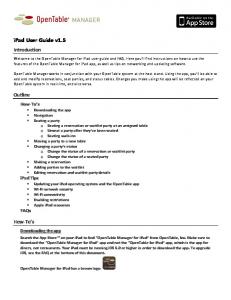
You can install the ANM server software on a standalone server or on a VMware virtual machine as shown in Figure 1-1. The capabilities and functions of the ANM software are the same regardless of which application you use. This guide uses the following terms to reference the two ANM applications: •
ANM server: Dedicated server with ANM server software and Red Hat Enterprise Linux (RHEL) operating system installed on it. For information about installing this type of ANM application, see the Installation Guide for the Cisco Application Networking Manager 4.2.
•
ANM Virtual Appliance: VMware virtual appliance with ANM server software and Cisco Application Delivery Engine Operating System (ADE OS) installed on it. Cisco distributes ANM Virtual Appliance in Open Virtual Appliance (.OVA) format. For information about installing this type of ANM application, see the Installation Guide for the Cisco Application Networking Manager 4.2 Virtual Appliance.
Figure 1-1
Sample ANM Network Deployment
Client Client
Physical Servers
Client
Cisco ANM
VMware vSphere Client
Cisco Nexus 7000
Cisco ACE
Standalone Server or Virtual Appliance
OTV/DCI Link (Dynamic Workload Scaling)
Virtual Machines
VM VMware vCenter
VM
VM VM VM
VM
VMware VMware ESX (i) Host ESX (i) Host
Virtual Machines
Cisco Nexus 7000
VM
VM
VM
VMware ESX (i) Host
Remote Data Center 300038
Local Data Center
Figure 1-1 shows how ANM and the ACE can be integrated with VMware, allowing you to create and manage server farms for application delivery that consist of real servers that are a combination of physical servers and VMware virtual machines (VMs). The sample network application also illustrates the following ANM and ACE features: •
Dynamic Workload Scaling—ACE feature that permits on-demand access to remote resources, such as VMs, that you own or lease from an Internet service provider (or cloud service provider). This feature uses Cisco’s Nexus 7000 series switches with Cisco’s Overlay Transport Virtualization (OTV), which is a Data Center Interconnect (DCI) technology used to create a Layer 2 link over an existing IP network between geographically distributed data centers. For more information, see the “Dynamic Workload Scaling Overview” section on page 7-4.
User Guide for the Cisco Application Networking Manager 4.2
1-2
OL-23969-01
Chapter 1
Overview Logging In To the Cisco Application Networking Manager
Note
•
Dynamic Workload Scaling requires ACE module or appliance software version A4(2.0) or later and the Cisco Nexus 7000 series switch.
ANM plug-in for vCenter Server—Enabling the plug-in on an ANM server or ANM Virtual Appliance permits access to ANM’s ACE server load-balancing functions from a VMware vSphere Client. For more information, see Appendix B, “Using the ANM Plug-In With Virtual Data Centers.”
Logging In To the Cisco Application Networking Manager You access ANM features and functions through a web-based interface. The following sections describe logging in, the interface, and terms used in ANM. The ANM login window allows you to do the following tasks: •
Log into the ANM server
•
Change the password for your account (see the “Changing Your Account Password” section on page 1-4)
•
Obtain online help by clicking Help
Procedure Step 1
Choose one the following: •
Note
Caution
To log in after a new install, which uses the default web ports of 443 and 80, enter https://host.
You do not have to explicitly enter the default ports 443 and 80.
If you log in using HTTP, you must change the properties file. See the “Changing ANM Software Configuration Attributes” section on page 18-1 for details. If you enable HTTP, you make your connection to ANM less secure. •
To log in after an upgrade, enter https://:10443 or https://:10080.
Note
You must explicitly enter the nondefault ports 10443 and 10080.
Note
All browsers require that cookies, Javascript/scripting, and popup windows are enabled. If you reinstall a subsequent ANM release, you must delete the cookies and clear the browser cache. For example, enter https://192.168.10.10:10443. The login window appears.
Step 2
In the User Name field, enter admin, which is the predefined user account that comes with a new installation.
User Guide for the Cisco Application Networking Manager 4.2 OL-23969-01
1-3
Chapter 1
Overview
Changing Your Account Password
Note
If you are logging in using ACS authentication (TACACS or RADIUS), you must add '@ to the username on the login page, or you will not be able to log in.
Once you are logged in using this account, you can create additional user accounts. For information on changing account passwords, see the “Modifying User Accounts” section on page 17-51. Step 3
In the Password field, enter the password that you configured the admin account with when installing ANM.
Step 4
Press Enter or click Login. When you log in, the default page that appears is the ANM Homepage (see the “ANM Windows and Menus” section on page 1-7). You can change your default page by making a different selection from the Homepage. See the “Customizing the Default ANM Page” section on page 2-4 for details. For a description of the user interface, see Figure 1-2 on page 1-6. The interface will not contain data until you add devices by one of the methods described in the “Importing Network Devices into ANM” section on page 4-9.
.
Related Topics •
Changing Your Account Password, page 1-4
•
ANM Interface Components, page 1-5
Changing Your Account Password You can change your account password. Procedure Step 1
Using a web browser, navigate to the ANM login window by typing the IP address or hostname where ANM is installed. For example, enter https://192.168.10.10. The login window appears.
Step 2
In the User Name field, enter your account username.
Step 3
Click Change Password. The Change password configuration window appears.
Step 4
In the User Name field, enter the username of the account that you want to modify.
Step 5
In the Old Password field, enter the current password for this account.
Step 6
In the New Password field, enter the new password for this account. Password attributes such as minimum and maximum length or accepted characters are defined at the organizational level. For more information on configuring passwords, see the “Configuring User Authentication and Authorization” section on page 17-40.
Step 7
In the Confirm New Password field, reenter the new password for this account.
Step 8
Do one of the following: •
Click OK to save your entries and to return to the login window.
•
Click Cancel to exit this procedure without saving your entries and to return to the login window.
User Guide for the Cisco Application Networking Manager 4.2
1-4
OL-23969-01
Chapter 1
Overview ANM Licenses
Related Topics •
Logging In To the Cisco Application Networking Manager, page 1-3
•
ANM Interface Components, page 1-5
ANM Licenses An ANM server license, which is available with the software at the time of purchase, must be uploaded to ANM after the installation in order for ANM to work properly. This license allows ANM to manage any number of supported devices and any number of ACE virtual contexts. The ANM demo license is also available, which allows ANM to perform all the functions associated with the ANM server license; however, the demo license has an expiration date associated with it. You can order a demo license if you do not know the PAK number required to order the ANM server license. When you install the ANM software, you also install the ANM license using the CLI as described in the Installation Guide for Cisco Application Networking Manager 4.2 or the Installation Guide for the Cisco Application Networking Manager 4.2 Virtual Appliance. After the initial installation of the ANM software and license, you can use ANM License Manager to check the status of the license or to add a new license, which you would need to do when converting from a demo license to an ANM server license. For more information, see the “Using ANM License Manager to Manage ANM Server or Demo Licenses” section on page 17-79. Related Topics •
Using ANM License Manager to Manage ANM Server or Demo Licenses, page 17-79
ANM Interface Components This section includes the following topics: •
ANM Windows and Menus, page 1-7
•
ANM Buttons, page 1-9
•
Table Conventions, page 1-11
•
ANM Screen Conventions, page 1-15
When you log in to ANM, the default window that appears is the Homepage from which you can access the operational and monitoring features of ANM. For details about using Homepage, see the “Information About Hompage” section on page 2-1). Figure 1-2 shows the Devices window (Config > Devices), which is an example ANM work window where you view the network device tree and perform network management tasks. Table 1-1 describes the numbered fields.
User Guide for the Cisco Application Networking Manager 4.2 OL-23969-01
1-5
Chapter 1
Overview
ANM Interface Components
Figure 1-2
Table 1-1
ANM Interface Components
ANM Interface Components Descriptions
Field
Description
1
Navigation pane, which contains the following components: •
High-level navigation path within the ANM interface, which includes Config, Monitor, and Admin. You can click an item in the navigation path to view that window.
•
Logout button.
•
Help button for providing context-sensitive help and a PDF version of the ANM user guide.
•
About button that provides ANM version information.
2
Second-level Navigation pane, which contains another level of navigation. Clicking an option in this pane displays the associated window in the content area.
3
Content area, which contains the display and input area of the window. It can include tables, configuration items, buttons, or combinations of these items.
4
Status bar, which indicates the date and time of the ANM server machine. ANM frequently updates the status bar. Related Topics •
ANM Windows and Menus, page 1-7
•
ANM Interface Components, page 1-5
•
Using Homepage, page 2-1
User Guide for the Cisco Application Networking Manager 4.2
1-6
OL-23969-01
Chapter 1
Overview ANM Interface Components
ANM Windows and Menus Figure 1-3 contains many common window elements found in ANM and described in Table 1-2. Not all windows contain all buttons. Figure 1-3
Example ANM Window
User Guide for the Cisco Application Networking Manager 4.2 OL-23969-01
1-7
Chapter 1
Overview
ANM Interface Components
Table 1-2
Example ANM Window Descriptions
Number Description 1
Device tree that appears when you click Config or Monitor. The device tree includes All Devices and Groups: folders •
The All Devices folder expands to show the names of imported Cisco devices and their associated modules or virtual contexts. When you click the plus sign (+) in front of a chassis icon, you can see a list of the modules in the chassis. When you expand an ACE appliance or ACE module, you can see the list of existing virtual contexts for that device. For more information about adding devices, see the “Importing Network Devices into ANM” section on page 4-9.
•
The Groups folder contains the list of user-defined groups. For more information about user-defined groups, see the “Configuring User-Defined Groups” section on page 4-70.
The Organization tree displays when you click Admin > Role-Based Access Control. The organization tree includes all organizations in ANM. Choosing an organization name displays its details. To expand folders in the device tree, click the plus sign (+) to the right of an option. To collapse the structure, click the minus sign (-). At the top of the tree are the following buttons: •
Refresh—Refreshes the device tree after you have imported devices or made changes to the User Groups.
•
Plus sign (+) —Allows you to add an item to the selected option in the device tree.
•
Garbage can—Deletes the selected entry.
Note
Menus are based on device types. Although menu labels are the same for different device types, the actual menu definition is different. For example, you cannot preserve the menu state while traversing back an forth from a module to a virtual context in the device tree.
2
Option menus, which appear in Config windows. Click the icon on the bar to show or hide the options.
3
Object selector. Use this field to choose a device, context, building block, or other object that you want to view information on or configure.
4
Command buttons. Use these buttons to perform the action identified by the button label.
5
Input fields. Use these fields to make selections and provide information. When there are more than three choices for any field, the field displays as a drop-down list. Otherwise, selections display with radio buttons.
6
Feature panel that contains functions that correspond to what is selected in the device or organization tree. Click on a command to expand the list of options that correspond to that command. Related Topics •
ANM Buttons, page 1-9
•
ANM Screen Conventions, page 1-15
User Guide for the Cisco Application Networking Manager 4.2
1-8
OL-23969-01
Chapter 1
Overview ANM Interface Components
ANM Buttons Table 1-3 describes the buttons that appear in some of the Config, Monitor, and Admin windows. Table 1-3
Button
Button Descriptions
Name
Description
ACL table (expand)
Allows you to expand all ACL table entries.
ACL table (collapse)
Allows you to collapse all ACL table entries.
ACL table (resequence)
Allows you to open the resequence popup window that allows you to reorder the ACL table entries.
Add
Allows you to add an entry to the displayed table.
Add another
Saves the current entries and refreshes the window so that you can add another entry.
Advanced editing mode
Allows you to view or enter advanced arguments for the chosen display.
Auto refresh (pause)
Allows you to interrupt the table data autorefresh process.
Auto refresh (resume)
Indicates that the table data autorefresh process is on pause and allows you to resume.
Customize
Allows you to customize the table to suit your needs. (See the “Customizing Tables” section on page 1-12.)
Delete
Deletes the chosen entry in the table.
Duplicate
Duplicates the chosen entry in the table.
User Guide for the Cisco Application Networking Manager 4.2 OL-23969-01
1-9
Chapter 1
Overview
ANM Interface Components
Table 1-3
Button
Button Descriptions (continued)
Name
Description
Edit
Opens the configuration window of a chosen entry in the table.
Filter
Filters the displayed list of items according to the criteria that you specify. (See the “Filtering Entries” section on page 1-12.) Also displays a filter text box where strings can be entered.
Go
Appears when filtering is enabled; updates the table with the filtering criteria.
Key
Indicates that the associated field is a foreign key field. This field takes its values from another table.
Plus
Displays a table with information related to the field where Plus appears. For example, if Plus appears next to the field label VLAN Group, clicking Plus displays a list of all VLAN groups in a separate window.
Refresh
Refreshes the content area.
Save
Displays the current information in a new window in either raw data or Microsoft Excel format so you can save it to a file or print it.
Full window view
Allows you to adopt a larger (full) window view for a table or dashboard window.
Reduced window view (normal)
Allows you to adopt a smaller window view for a table or dashboard window.
Sort
Sorts a column alphabetically up or down.
Stop
Stops the current process. If a process is only partially complete, it will finish its current operation and exit. For example, when stop is used during the import of two modules, it will complete only the first of two module imports.
User Guide for the Cisco Application Networking Manager 4.2
1-10
OL-23969-01
Chapter 1
Overview ANM Interface Components
Table 1-3
Button
Button Descriptions (continued)
Name
Description
Switch between configure and browse modes
Displays the subtables for those items that have additional sets of parameters that can be configured, such as Config > Devices > Network > VLAN Interfaces. Note
This button is not available on single-row tables such as Config > Devices > System > Syslog or Config > Devices > System > SNMP. To switch between these modes, navigate to another window where the button appears (for example, Config > Devices > Load Balancing > Server Farms), click the button to enter desired mode, then return to the window on which the button was missing. You will remain in the mode you chose.
View Excel
Displays the raw data in Microsoft Excel format in a separate browser window.
View raw data
Displays the raw data in table format.
Show as image
Displays the historical data object graph in a separate browser window.
View as chart
Toggles the display of a historical data object as a graph in the monitoring window.
View as grid
Toggles the display of a historical data object as a numerical grid in the monitoring window. From this display, you can export the data in Microsoft Excel format.
Related Topics •
ANM Windows and Menus, page 1-7
•
ANM Screen Conventions, page 1-15
Table Conventions This section describes the ANM GUI table conventions, including how to filter the information displayed and how to customize a table’s appearance. This section includes the following topics: •
Filtering Entries, page 1-12
•
Customizing Tables, page 1-12
•
Using the Advanced Editing Option, page 1-14
User Guide for the Cisco Application Networking Manager 4.2 OL-23969-01
1-11
Chapter 1
Overview
ANM Interface Components
Filtering Entries You can filter the information that a table displays. Click Filter to view table entries using the criteria that you chose. When filtering is enabled, a filter row appears above the first table entry that allows you to filter entries in the following ways: •
In fields with drop-down lists, choose one of the ANM-identified categories (see Figure 1-4). The table refreshes automatically with the entries that match the chosen criterion.
•
In fields without drop-down lists, enter the string that you want to match, and then click Go above the first table entry. The table refreshes with the entries that match your input.
•
Enter the string in the filter box. For example, by entering the string gold and clicking Go, only the gold Resource Class virtual contexts appear (see Figure 1-4).
Figure 1-4
Example Table with Filtering Enabled
Related Topics •
ANM Interface Components, page 1-5
•
Customizing Tables, page 1-12
•
Using the Advanced Editing Option, page 1-14
Customizing Tables You can customize a table for your use. Click Customize in a table to configure the table to suit your needs. When you place the cursor over Customize, the following items appear: •
Default—When chosen with a check mark, this item indicates that the ANM default table format is being used by the current table.
•
Configure—When chosen, this item opens a dialog box that allows you to create a new customized table format or to modify the table format currently in use.
Procedure Step 1
When viewing a table, choose Customize > Configure. The List Configuration dialog box appears.
Step 2
In the List Configuration dialog box, enter the information in Table 1-4.
Note
Depending on the table that you chose, the available fields in the configuration table differ. Table 1-4 includes sample fields that might appear.
User Guide for the Cisco Application Networking Manager 4.2
1-12
OL-23969-01
Chapter 1
Overview ANM Interface Components
Note
Table 1-4
You can be as inclusive or as restrictive as you like when setting table configuration options.
Table Configuration Attributes
Field
Description
List Customization Name
Unique name for a new table configuration.
Fields
Fields that you can include in the table, choose the fields from the Available Items list, and click Add. To remove fields from the table, choose the fields from the Selected Items list, and then click Remove.
Up/Down
Location of a column in the table that you can change. Choose its name in the column on the right, then click Up or Down to place it in the desired location.
Group By
Field that you want to group entries by. When you choose a field for grouping, one or more entries appears in the table with + at the beginning of the entry, the name of the field, the grouping criteria, and the number of items in the group. Click + to view all entries in the group.
Descending
Descending check box to sort the groups in reverse order. Clear the Descending check box to sort the groups in ascending order.
Sort By
Field that you want to sort entries by. When you choose a field for sorting, all entries in the table are sorted according to the values in the selected field.
Name Filter
Name that represents the name of each field in the table. Enter the string or value that you want to filter the results by. You can enter complete or partial strings or values to be matched. Do not include wildcard characters.
Version Filter
Version that represents the name of each field in the table. Enter the string or value that you want to filter the results by. You can enter complete or partial strings or values to be matched. Do not include wildcard characters.
Step 3
Do one of the following: •
Click Save to save your entries under a new name and to close the List Configuration dialog box. If a table using this format is displayed, the table is updated automatically.
•
Click Cancel to exit the procedure without saving your entries and to close the List Configuration dialog box.
•
Click Apply to apply your current entries to the table that you are viewing, to save your entries, and to close the List Configuration dialog box.
•
Click Delete to delete the currently selected customized table format. It no longer appears as an option when you click Customize.
User Guide for the Cisco Application Networking Manager 4.2 OL-23969-01
1-13
Chapter 1
Overview
ANM Interface Components
Related Topics •
ANM Interface Components, page 1-5
•
Filtering Entries, page 1-12
•
Using the Advanced Editing Option, page 1-14
Using the Advanced Editing Option By default, tables include columns that contain configured attributes or a subset of columns related to a key field. To view all configurable attributes in table format, click Advanced Editing Mode (the highlighted button in Figure 1-5). When advanced editing mode is enabled, all columns appear for your review (see Figure 1-5). Figure 1-5
Advanced Editing Enabled Window
Related Topics •
ANM Interface Components, page 1-5
•
Filtering Entries, page 1-12
•
Customizing Tables, page 1-12
User Guide for the Cisco Application Networking Manager 4.2
1-14
OL-23969-01
Chapter 1
Overview ANM Interface Components
ANM Screen Conventions Table 1-5 describes other conventions used in ANM screens. Table 1-5
ANM Window Conventions
Convention
Example
Description
Dimmed field
If no items are selected, buttons are dimmed. If an item is selected, only operational buttons appear.
Red asterisk
A red asterisk indicates a required field.
Yellow field with red font
Incorrect, invalid, or incomplete entries appear as red font against a yellow background with the reason for that error. In the example, an IP address cannot begin with four digits, which results in this display.
Drop-down lists
When there are more than three choices for any field, the field displays as a drop-down list. Otherwise, selections display with radio buttons.
Related Topics •
Table Conventions, page 1-11
•
ANM Interface Components, page 1-5
User Guide for the Cisco Application Networking Manager 4.2 OL-23969-01
1-15
Chapter 1
Overview
ANM Interface Components
User Guide for the Cisco Application Networking Manager 4.2
1-16
OL-23969-01
CH A P T E R
2
Using Homepage This section describes how to use Homepage, which is a launching point for quick access to selected areas within Cisco Application Networking Manager (ANM). This chapter includes the following sections: •
Information About Hompage, page 2-1
•
Customizing the Default ANM Page, page 2-4
Information About Hompage Homepage allows you to have quick access to the following operations and guided setup tasks in ANM: •
Operational tasks that you can access: – The Real Servers table to view information for each configured real server, activate or suspend
real servers listed in the table, or modify server weight and connection limits. – The Virtual Servers table to view information for each configured virtual server and to activate
or suspend virtual servers listed in the table. – The Cisco Global Site Selector (GSS) Answer table to manage GSS VIP answers (resources that
respond to content queries) by specifying virtual IP (VIP) addresses associated with a server load balancer (SLB) such as the Cisco Content Services Switch (CSS), Cisco Content Switching Module (CSM), Cisco IOS-compliant SLB, LocalDirector, or a web server. – The DNS Rules table to specify actions in the DNS rules table for the GSS to take when it
receives a request from a known source (a member of a source address list) for a known hosted domain (a member of a domain list). •
Monitoring—Connect to the central Device Dashboard where you can quickly view device and virtual context monitoring results and track potential issues; view detailed context-level resource usage information; and monitor load balancing statistics for virtual servers.
•
Guided setup tasks that you can launch: – The Import Devices guided setup task to establish communication between ANM and hardware
devices. – The Cisco Application Control Engine (ACE) Hardware Setup task to configure ACE devices
that are new to the network by establishing network connectivity in either standalone or high-availability (HA) deployments. – The Virtual Context Setup task to create and connect an ACE virtual context. – The Application Setup task to configure end-to-end load-balancing for your application.
User Guide for the Cisco Application Networking Manager 4.2 OL-23969-01
2-1
Chapter 2
Using Homepage
Information About Hompage
•
Configuration—Tasks that allow you to configure system attributes for a virtual context, control a user’s access to ANM, and display configuration and deployment changes logged in the ANM database.
•
Documentation—Quick links to ANM, ACE module, and ACE appliance user documentation on www.cisco.com.
•
System Summary—Tasks that allow you to display critical alarm notifications when the value for a specific statistic rises above the specified setting or display all critical events received from an ACE device for syslog and SNMP traps from all virtual contexts.
By default, the ANM Homepage (see Figure 2-1) is the first page that appears in ANM after you log in. To access the Homepage from other locations within ANM, click the Home menu option at the top of the window. From the Homepage, you can customize which page you want to display for subsequent logins into ANM. See the “Customizing the Default ANM Page” section on page 2-4 for details.
Note
All menu options on the Homepage are under Role-Based Access Control (RBAC). Menu options will be grayed if proper permission has not been granted to the logged in user by the administrator. See the “How ANM Handles Role-Based Access Control” section on page 17-8 for more information about RBAC in ANM. Figure 2-1
Homepage Window
User Guide for the Cisco Application Networking Manager 4.2
2-2
OL-23969-01
Chapter 2
Using Homepage Information About Hompage
Table 2-1 identifies the Homepage links, associated pages in ANM, and related topics that can be found in this document. Table 2-1
Homepage Links
Homepage Link
ANM Page
Related Topics
Manage Real Servers
Config > Operations > Real Servers
Managing Real Servers, page 7-9
Manage Virtual Servers
Config > Operations > Virtual Servers
Managing Virtual Servers, page 6-67
Manage GSS VIP Answers
Config > Operations > GSS VIP Answers
Managing GSS VIP Answers, page 6-69
Manage GSS DNS Rules
Config > Operations > DNS Rules
Activating and Suspending DNS Rules Governing GSS Load Balancing, page 6-70
Dashboard
Monitor > Devices > Dashboard
Using Dashboards to Monitor Devices and Virtual Contexts, page 16-4
Resource Usage Summary
Monitor > Devices > Resource Usage > Connections
Monitoring System Traffic Resource Usage, page 16-27
Application Performance Summary
Monitor > Devices > Load Balancing > Virtual Servers
Monitoring Load Balancing, page 16-33
Import a Device
Config > Guided Setup > Import Devices
Using Import Devices, page 3-3
Configure ACE Hardware
Config > Guided Setup > ACE Hardware Setup
Using ACE Hardware Setup, page 3-4
Create a Virtual Context
Config > Guided Setup > Virtual Context Setup
Using Virtual Context Setup, page 3-9
Provision an Application
Config > Guided Setup > Application Setup
Using Application Setup, page 3-11
Configure Devices
Config > Devices > System > Primary Attributes
Configuring Virtual Context Primary Attributes, page 5-12
ANM Role-Based Access Control
Admin > Role-Based Access Control > Users
Managing User Accounts, page 17-48
Device Audit
Config > Device Audit
Performing Device Audit Trail Logging, page 17-83
Critical Alarms
Monitor > Alarm Notifications > Alarms
Displaying Alarms in ANM, page 16-61
High Priority Syslogs
Monitor > Events > Events
Monitoring Events, page 16-52
Operational Tasks
Monitoring
Guided Setup
Configuration
System Summary
Documentation Cisco ANM Documentation N/A (link to documentation set on www.cisco.com)
N/A
Cisco ACE Appliance N/A Documentation (link to documentation set on www.cisco.com)
N/A
User Guide for the Cisco Application Networking Manager 4.2 OL-23969-01
2-3
Chapter 2
Using Homepage
Customizing the Default ANM Page
Table 2-1
Homepage Links (continued)
Homepage Link
ANM Page
Related Topics
Operational Tasks Cisco ACE Module N/A Documentation (link to documentation set on www.cisco.com)
N/A
Cisco ACE Module Troubleshooting Wiki (link to DocWiki)
N/A
N/A
Customizing the Default ANM Page You can choose the default page that you access after logging in to ANM. By default, the ANM Homepage is the first page that appears after you log in. From the ANM Homepage, you can specify a different page that appears as the default page after you log in. Procedure Step 1
If the Homepage is not active in ANM, click the Home tab. The Homepage appears.
Step 2
From the Select a New Default Page drop-down list, choose one of the following pages that you want to appear after you log in to ANM: •
Home > Welcome
•
Config > Guided Setup
•
Config > Devices
•
Config > Operations > Real Servers
•
Config > Operations > Virtual Servers
•
Config > Operations > GSS VIP Answers
•
Config > Operations > GSS DNS Rules
•
Config > Deploy
•
Config > Device Audit
•
Monitor > Devices > Dashboard
•
Monitor > Devices > Resource Usage
•
Monitor > Devices > Traffic Summary
•
Monitor > Devices > Load Balancing > Real Servers
•
Monitor > Devices > Load Balancing > Probes
•
Monitor > Devices > Load Balancing > Statistics
•
Monitor > Devices > Load Balancing > Application Acceleration (ACE appliance only)
•
Monitor > Events
•
Monitor > Alarm Notifications > Alarms
User Guide for the Cisco Application Networking Manager 4.2
2-4
OL-23969-01
Chapter 2
Using Homepage Customizing the Default ANM Page
Step 3
Click Save to save your new selection as the default page the next time that you log in to ANM.
User Guide for the Cisco Application Networking Manager 4.2 OL-23969-01
2-5
Chapter 2
Using Homepage
Customizing the Default ANM Page
User Guide for the Cisco Application Networking Manager 4.2
2-6
OL-23969-01
CH A P T E R
3
Using ANM Guided Setup Date: 2/21/11
This chapter describes how to use Cisco Application Networking Manager (ANM) Guided Setup.
Note
When naming ACE objects (such as a real server, virtual server, parameter map, class map, health probe, and so on), enter an alphanumeric string of 1 to 64 characters, which can include the following special characters: underscore (_), hyphen (-), dot (.), and asterisk (*). Spaces are not allowed. If you are using ANM with an ACE module or ACE appliance and you configure a named object at the ACE CLI, keep in mind that ANM does not support all of the special characters that the ACE CLI allows you to use when configuring a named object. If you use special characters that ANM does not support, you may not be able to import or manage the ACE using ANM. This chapter includes the following sections: •
Information About Guided Setup, page 3-1
•
Guidelines and Limitations, page 3-3
•
Using Import Devices, page 3-3
•
Using ACE Hardware Setup, page 3-4
•
Using Virtual Context Setup, page 3-9
•
Using Application Setup, page 3-11
Information About Guided Setup ANM Guided Setup provides a series of setup sequences that offer GUI window guidance and networking diagrams to simplify the configuration of ANM and the network devices that it mananges. Guided Setup allows you to quickly perform the following tasks: •
Establish communication between ANM and Application Control Engine (ACE) hardware devices.
•
Configure ACE devices that are new to the network by establishing network connectivity in either standalone or high-availability (HA) deployments.
•
Create and connect to an ACE virtual context.
•
Set up load balancing application from an ACE to a group of back-end servers.
To access Guided Setup, click the Config tab located at the top of the window, then click Guided Setup.
User Guide for the Cisco Application Networking Manager 4.2 OL-23969-01
3-1
Chapter 3
Using ANM Guided Setup
Information About Guided Setup
Note
The available menu and button options on the Guided Setup tasks are under Role-Based Access Control (RBAC). Menu and button options will be grayed if proper permission has not been granted to the logged in user by the administrator. See the “How ANM Handles Role-Based Access Control” section on page 17-8 for more information about RBAC in ANM. Table 3-1 identifies the individual guided setup tasks and related topics.
Table 3-1
Guided Setup Tasks and Related Topics
Guided Setup Tasks
Purpose
Import devices
Launch the Import Devices setup task to establish communication between ANM and hardware devices. Imported devices can include: ACE modules, ACE appliances, Catalyst 6500 series chassis, Catalyst 6500 Virtual Switching System (VSS) 1440, Cisco 7600 series routers, Content Services Switches (CSS) devices, Content Switching Module (CSM) devices, or Global Site Selector (GSS) devices.
•
Using Import Devices, page 3-3
•
Information About Importing Devices, page 4-3
•
Preparing Devices for Import, page 4-4
•
Importing Network Devices into ANM, page 4-9
•
Discovering Large Numbers of Devices Using IP Discovery, page 4-25
Launch the ACE Hardware Setup task to help you configure ACE devices that are new to the network by establishing network connectivity in either standalone or high-availability (HA) deployments.
•
Using ACE Hardware Setup, page 3-4
•
Configuring Devices, page 4-32
•
Configuring ACE Module and Appliance Role-Based Access Controls, page 4-51
•
Managing Devices, page 4-64
•
Configuring ACE High Availability Peers, page 12-14
•
Using Virtual Context Setup, page 3-9
•
Using Resource Classes, page 5-41
•
Creating Virtual Contexts, page 5-2
•
Configuring Virtual Contexts, page 5-7
•
Configuring VLANs Using Cisco IOS Software (ACE Module), page 11-3
•
Using Application Setup, page 3-11
•
Configuring VLAN Interfaces, page 11-5
•
Configuring Virtual Context BVI Interfaces, page 11-13
•
Configuring Virtual Context Static Routes, page 11-18
•
Configuring Virtual Context BVI Interfaces, page 11-13
•
Configuring Security with ACLs, page 5-74
•
SSL Setup Sequence, page 10-4
ACE hardware setup
Virtual context setup
Application setup
Launch the Virtual Context Setup task to create and connect an ACE virtual context.
Launch the Application Setup task to configure load balancing for your application. This task guides you through a complete end-to-end configuration of the ACE for many common server load-balancing situations.
Related Topics
User Guide for the Cisco Application Networking Manager 4.2
3-2
OL-23969-01
Chapter 3
Using ANM Guided Setup Guidelines and Limitations
Guidelines and Limitations As you perform a Guided Setup task, use the following operating conventions: •
To move between steps, click the name of the step in the menu to the left.
•
The steps for each task are listed in an order that is designed to prevent problems during later steps; however, you can skip steps if you know they are not applicable to your application.
•
Depending on your user privileges, ANM may prevent you from making changes on certain steps.
•
You must save and deploy any changes you want to keep before leaving each page.
•
Each task can be run as many times as you like.
Using Import Devices You can use the Import Device task to import ACE modules, ACE appliances, Catalyst 6500 series chassis, Catalyst 6500 Virtual Switching System (VSS) 1440, Cisco 7600 series routers, CSS devices, CSM devices, or GSS devices into ANM. You must import the hardware devices before ANM can manage them. Before You Begin •
Because ANM communicates with network devices through Secure Shell (SSH) and other protocols, you must set up your devices to allow ANM to collect data from them. See the “Preparing Devices for Import” section on page 4-4.
•
Before ANM can import a device, you must ensure that the device has a management interface that ANM can access. Also, you need the IP address and credentials for the device's management interface in order to import it.
•
If the ACE module is new and retains its factory settings, you can configure basic management during the import process by using the Bare Blade option.
Procedure Step 1
Choose Config > Guided Setup > Import Devices. The Import Devices window appears, which includes the All Devices table.
Step 2
At the top of the All Devices table, click Add (+) to import a new device. The New Device window appears.
Step 3
Enter the information for the specific device and complete the import devices procedure as described in “Importing Network Devices into ANM” section on page 4-9.
Note
To manage modules inside a Catalyst 6500 series switch, you must first import the Catalyst into the All Devices table. To import modules from a Catalyst that is already imported, choose the Catalyst switch from the All Devices table and click Modules below the All Devices table.
User Guide for the Cisco Application Networking Manager 4.2 OL-23969-01
3-3
Chapter 3
Using ANM Guided Setup
Using ACE Hardware Setup
Note
Step 4
The time required to import depends on the size of the existing configuration on each device. The process can range from a few minutes to 30 minutes or more for a very large configuration.
After you finish importing the ACE devices (module or appliance) into ANM, continue to the ACE Hardware Setup task to guide you through the basic device setup and network configuration. See the “Using ACE Hardware Setup” section on page 3-4.
Related Topics •
Information About Importing Devices, page 4-3
•
Preparing Devices for Import, page 4-4
•
Importing Network Devices into ANM, page 4-9
•
Discovering Large Numbers of Devices Using IP Discovery, page 4-25
•
Using ACE Hardware Setup, page 3-4
Using ACE Hardware Setup You can use the ACE Hardware Setup task to configure ACE devices that are new to the network by establishing network connectivity in either standalone or high-availability (HA) deployments. Before You Begin
Before you can set up the ACE hardware using ANM, you must use the Import Devices task to import the ACE into ANM if you have not already. See the “Using Import Devices” section on page 3-3. Assumptions •
Note
You can extend the functionality of the ACE by installing licenses. If you plan to extend the ACE functionality, ensure that you have received the proper software license key for the ACE, that ACE licenses are available on a remote server for importing to the ACE, or you have received the software license key and have copied the license file to the disk0: file system on the ACE using the copy path/]filename1 disk0: CLI command.
See either the Cisco Application Control Engine Module Administration Guide or Cisco 4700 Series Application Control Engine Appliance Administration Guide for details on the copy path/]filename1 disk0: CLI command.
•
You must be in the Admin virtual context on an ACE device (ACE module or ACE appliance) to configure ACE devices that are new to the network.
•
When importing an ACE HA pair into ANM, you should follow one of the following configuration requirements so that ANM can uniquely identify the ACE HA pair: – Use a unique combination of FT interface VLAN and FT IP address/peer IP address for every
ACE HA pair imported into ANM. For HA, it is critical that the combination of FT interface VLAN and IP address/peer IP address is always unique across every pair of ACE peer devices.
User Guide for the Cisco Application Networking Manager 4.2
3-4
OL-23969-01
Chapter 3
Using ANM Guided Setup Using ACE Hardware Setup
– Define a peer IP address in the management interface using the management IP address of the
peer ACE (module or appliance). The management IP address and management peer IP address used for this definition should be the management IP address used to import both ACE devices into ANM.
Note
•
For more information about the use of HA pairs imported into ANM, see “ANM Requirements for ACE High Availability” section on page 4-7. When you are configuring the ACE, changes to the physical interfaces (including Gigabit Ethernet ports or port channels) can result in a loss of connectivity between ANM and the ACE. Use caution when following the ACE Hardware Setup task if you are modifying the interface that management traffic is traversing.
Procedure Step 1
Choose Config > Guided Setup > ACE Hardware Setup. The ACE Hardware Setup window appears, which includes the ACE Device and Configuration Type drop-down lists.
Step 2
From the ACE Device drop-down list, choose an ACE device (module or appliance).
Step 3
From the Configuration Type drop-down list, choose whether to set up the ACE as a standalone device or as a member of a high-availability (HA) ACE pair: •
Standalone—The ACE is not to be used in an HA configuration.
•
HA Secondary—The ACE is to be the secondary peer in an HA configuration.
•
HA Primary—The ACE is to be the primary peer in an HA configuration.
Note
Step 4
Ensure that you complete the ACE hardware setup task for the secondary device before you set up the primary device.
Click Start Setup. The License window appears (Config > Guided Setup > ACE Hardware Setup > Licenses). Cisco offers licenses for ACE modules and appliances that allows you to increase the number of default contexts, bandwidth, and SSL TPS (transactions per second). For more information, see either the Cisco Application Control Engine Module Administration Guide or to the Cisco 4700 Series Application Control Engine Appliance Administration Guide on cisco.com. If you need to install licenses at this point, go to Step 5. If you do not need to install licenses at this point, go to Step 6.
Step 5
Install one or more ACE licenses (see the “Managing ACE Licenses” section on page 5-34).
Note
For an ACE primary and secondary HA pair, because each ACE license is only valid on a single hardware device, licenses are not synchronized between HA peer devices. You must install an appropriate version of each license independently on both the primary and secondary ACE devices.
User Guide for the Cisco Application Networking Manager 4.2 OL-23969-01
3-5
Chapter 3
Using ANM Guided Setup
Using ACE Hardware Setup
Step 6
Click SNMP v2c Read-Only Community String under ACE Hardware Setup (Config > Guided Setup > ACE Hardware Setup > SNMP v2c Read-Only Community String). The SNMP v2c Read-Only Community String window appears. Perform the following actions to configure an SNMP community string (a requirement for an ACE to be monitored by ANM): a.
Click Add (+) at the top of the SNMP v2c Read-Only Community String table to create an SNMP community string. The New SNMP v2c Community window appears.
Note
b.
For ANM to monitor an ACE, you must configure an SNMPv2c community string in the Admin virtual context.
In the Read-Only Community field, enter the SNMP read-only community string name. Valid entries are unquoted text strings with no spaces and a maximum of 32 characters.
Additional SNMP configuration selections are available under Config > Devices > context > System > SNMP. See the “Configuring SNMP for Virtual Contexts” section on page 5-25. Step 7
If you are configuring an ACE appliance, to group physical ports together on the ACE appliance to form a logical Layer 2 interface called the port-channel (sometimes known as EtherChannels), click Port Channel Interfaces under ACE Hardware Setup. The Port Channel Interfaces window appears (Config > Guided Setup > ACE Hardware Setup > Port Channel Interfaces).
Note
You must configure port channels on both the ACE appliance and the switch that the ACE is connected to.
Perform the following actions to configure a port channel interface: a.
If you want to poll the devices and display the current values, click Poll Now, and then OK when prompted if you want to poll the devices for data now.
b.
At the top of the Port Channel Interfaces table, click Add (+) to add a port channel interface, or choose an existing port channel interface and click Edit to modify it. The New Port Channel Interface window appears.
Note
If you click Edit, not all of the fields can be modified.
c.
Enter the port channel interface attributes as described in the “Configuring Port-Channel Interfaces for the ACE Appliance” section on page 11-24.
d.
Click Deploy Now to deploy this configuration on the ACE and save your entries to the running-configuration and startup-configuration files.
e.
To display statistics and status information for a port-channel interface, choose the interface from the Port Channel Interfaces table and click Details. The show interface port-channel CLI command output appears. See the “Displaying Port Channel Interface Statistics and Status Information” section on page 11-29 for details.
User Guide for the Cisco Application Networking Manager 4.2
3-6
OL-23969-01
Chapter 3
Using ANM Guided Setup Using ACE Hardware Setup
Step 8
Step 9
If you are configuring an ACE appliance, to configure one or more of the Gigabit Ethernet ports on the appliance, click GigabitEthernet Interfaces under ACE Hardware Setup. The GigabitEthernet Interfaces window appears (Config > Guided Setup > ACE Hardware Setup > GigabitEthernet Interfaces). a.
If you want to poll the devices and display the current values, click Poll Now, and then OK when prompted if you want to poll the devices for data now.
b.
Choose an existing Gigabit Ethernet interface and click Edit to modify it.
c.
Enter the Gigabit Ethernet physical interface attributes as described in the “Configuring Gigabit Ethernet Interfaces on the ACE Appliance” section on page 11-21.
d.
Click Deploy Now when completed to deploy this configuration on the ACE and save your entries to the running-configuration and startup-configuration files.
e.
Repeat Steps a through c for each Gigabit Ethernet interface that you want to configure.
f.
To display statistics and status information for a particular Gigabit Ethernet interface, choose the interface from the GigabitEthernet Interfaces table, then click Details. The show interface gigabitEthernet CLI command output appears. See the “Displaying Gigabit Ethernet Interface Statistics and Status Information” section on page 11-24 for details.
If the ACE is a member of an HA ACE pair, click VLAN Interfaces under ACE Hardware Setup. The VLAN Interfaces window appears (Config > Guided Setup > ACE Hardware Setup > VLAN Interfaces).
Note
To prevent loss of management connectivity during an HA configuration, you must configure the IP addresses of the management VLAN interface correctly for your HA setup. During this procedure, choose the management VLAN interface (and click the Edit button) and make sure its IP address, alias IP address, and peer IP address are all set correctly. You can repeat this process for any VLAN interfaces that you want. If the management VLAN is properly configured before establishing HA, you will be able to return later to reconfigure other VLANs.
a.
If you want to poll the devices and display the current values, click Poll Now, and then OK when prompted if you want to poll the devices for data now.
b.
Click Add to add a new VLAN interface, or choose an existing VLAN interface and click Edit to modify it.
Note
If you click Edit, not all of the fields can be modified.
c.
Enter the VLAN interface attributes as described in the “Configuring VLAN Interfaces” section on page 11-5. Click More Settings to access the additional VLAN interface attributes. By default, ANM hides the default VLAN interface attributes and the VLAN interface attributes which are not commonly used.
d.
Click Deploy Now to deploy this configuration on the ACE and save your entries to the running-configuration and startup-configuration files.
e.
To display statistics and status information for a VLAN interface, choose the VLAN interface from the VLAN Interface table, then click Details. The show interface vlan CLI command output appears. See the “Displaying VLAN Interface Statistics and Status Information” section on page 11-12 for details.
User Guide for the Cisco Application Networking Manager 4.2 OL-23969-01
3-7
Chapter 3
Using ANM Guided Setup
Using ACE Hardware Setup
Step 10
If the ACE is the primary peer in a high availability (HA) configuration, click HA Peering under ACE Hardware Setup (Config > Guided Setup > ACE Hardware Setup > HA Peering). a.
Click Edit below the HA Management section to configure the primary ACE and the secondary ACE as described in the “Configuring ACE High Availability Peers” section on page 12-14. There are two columns, one for the selected ACE and another for a peer ACE. You can specify the following information: – Identify the two members of a HA pair. – Assign IP addresses to the peer ACEs. – Assign an HA VLAN to HA peers and bind a physical Gigabit Ethernet interface to the FT
VLAN. – Configure the heartbeat frequency and count on the peer ACEs in a fault-tolerant VLAN.
When completed, click Deploy Now to deploy this configuration on the ACE and save your entries to the running-configuration and startup-configuration files.
Note
b.
For ACE modules, the HA VLAN specified for ACE HA Groups must also be set up on the Catalyst 6500 series switch using the svclc command. See the “Configuring VLANs Using Cisco IOS Software (ACE Module)” section on page 11-3 for details.
Click Add below the ACE HA group table to add a new high availability group. Enter the information in the configurable fields as described in the “Configuring ACE High Availability Peers” section on page 12-14. When completed, click Deploy Now to deploy this configuration on the ACE and save your entries to the running-configuration and startup-configuration files. The HA State field displays FT VLAN Compatible once HA setup has been successfully completed.
Note
Step 11
To display statistics and status information for a particular HA group, choose the group from the ACE HA Groups table and click Details. The show ft group group_id detail CLI command output appears. See the “Displaying High Availability Group Statistics and Status Information” section on page 12-22 for details.
Once the HA State field in the ACE HA Groups table shows a successful state, the ACE is ready for further configuration as follows: •
To set up additional virtual contexts, continue to the Virtual Context Setup task to create and connect an ACE virtual context. See the “Using Virtual Context Setup” section on page 3-9.
•
To set up an application in an existing virtual context, continue to the Application Setup task to set up load-balancing for an application from an ACE to a group of back-end servers. See the “Using Application Setup” section on page 3-11.
Related Topics •
Using Import Devices, page 3-3
•
Configuring Devices, page 4-32
•
Configuring ACE Module and Appliance Role-Based Access Controls, page 4-51
•
Managing Devices, page 4-64
User Guide for the Cisco Application Networking Manager 4.2
3-8
OL-23969-01
Chapter 3
Using ANM Guided Setup Using Virtual Context Setup
Using Virtual Context Setup You can use the Virtual Context Setup task to create and connect an ACE virtual context. Virtual contexts use virtualization to partition your ACE appliance or module into multiple virtual devices, or contexts. Each context contains its own set of policies, interfaces, resources, and administrators. Before You Begin
You must be in the Admin context on the ACE to create a new user context. Procedure Step 1
Choose Config > Guided Setup > Virtual Context Setup. The Virtual Context Setup window appears.
Step 2
From the ACE Device drop-down list, choose an ACE.
Step 3
Click Start Setup. The Resource Classes window appears (Config > Guided Setup > Virtual Context Setup > Resource Classes). Perform the following tasks to create or modify a resource class: a.
If you want to create a resource class, click Add (+). The New Resource Class configuration window appears. Enter the resource information as described in the “Configuring Global Resource Classes” section on page 5-44.
b.
If you want to modify an existing resource, choose the resource class that you want to modify, then click Edit. The Edit Resource Class configuration window appears. Enter the resource information as described in the “Modifying Global Resource Classes” section on page 5-48.
c.
Click OK to save your entries and to return to the Resource Classes table.
Make note of the resource class that you want to use because you will need it in Step 5. Step 4
Click Virtual Context Management under Virtual Context Setup. The Virtual Context window appears (Config > Guided Setup > Virtual Context Setup > Virtual Context Management). Perform the following actions to create or modify a virtual context:
Step 5
a.
If you want to create a virtual context, click Add (+). The New Virtual Context window appears. Configure the virtual context as described in the “Configuring Virtual Contexts” section on page 5-7.
b.
If you want to modify an existing virtual context, choose the virtual context that you want to modify and click Edit. The Edit Resource Class configuration window appears. Enter the resource information as described in the “Modifying Global Resource Classes” section on page 5-48.
To create or modify the attributes of a virtual context, configure the virtual context as described in the “Configuring Virtual Contexts” section on page 5-7. When completed, click Deploy Now to deploy this configuration on the ACE and save your entries to the running-configuration and startup-configuration files. Follow these guidelines when creating or modifying the virtual context: •
To connect the virtual context to the available VLANs, specify one or more VLANs in the Allocated VLANs field. You can specify multiple VLAN values and ranges (for example, “10, 14, 70-79”).
•
For virtual contexts configured for an ACE, do the following:
User Guide for the Cisco Application Networking Manager 4.2 OL-23969-01
3-9
Chapter 3
Using ANM Guided Setup
Using Virtual Context Setup
– For an ACE appliance, you must set up all VLANs used in this step as trunk or access VLANs
on the port channel or Gigabit Ethernet interfaces. If you did not set up these VLANs during the ACE Hardware Setup task, you can return to the ACE Hardware Setup window to configure the required VLANs. See the “Using ACE Hardware Setup” section on page 3-4. – For an ACE module, you must set up all VLANs used in this step as trunk or access VLANs on
the Catalyst 6500 series switch using the svclc command. See the “Configuring VLANs Using Cisco IOS Software (ACE Module)” section on page 11-3 for details. •
When specifying the resource class for the virtual context, choose the resource class that you created or specified in Step 3.
Note
•
If HA has been correctly configured for this ACE device, the High Availability checkbox will be checked. If the checkbox is unchecked, check it to instruct ANM to automatically configure synchronization for this virtual context.
Note
•
Step 6
If you are unsure of the resource class to use for this virtual context, choose default. You can change the resource class setting at a later time.
The High Availability checkbox is available only if HA Peering has previously been completed for the ACE hardware.
If you want to set up a separate management VLAN interface for the virtual context, under Management Settings, configure the management interface for this virtual context and create an admin user. Each context also has its own management VLAN that you can access using the ANM GUI. In this case, you would assign an independent VLAN and IP address for management traffic to access the virtual context.
To edit the load-balancing configuration for a virtual context, continue to the Application Setup task. See the “Using Application Setup” section on page 3-11. Related Topics •
Using Import Devices, page 3-3
•
Using ACE Hardware Setup, page 3-4
•
Information About Virtual Contexts, page 5-2
•
Using Resource Classes, page 5-41
•
Creating Virtual Contexts, page 5-2
•
Configuring Virtual Contexts, page 5-7
•
Configuring VLANs Using Cisco IOS Software (ACE Module), page 11-3
•
Using Application Setup, page 3-11
User Guide for the Cisco Application Networking Manager 4.2
3-10
OL-23969-01
Chapter 3
Using ANM Guided Setup Using Application Setup
Using Application Setup This section includes the following topics on application setup: •
ACE Network Topology Overview, page 3-11
•
Using Application Setup, page 3-12
ACE Network Topology Overview With respect to ACE configuration, the network topology describes where—which VLAN or subnet—client traffic comes into the ACE and where this traffic is sent to real servers. Network configuration for ACE load balancing depends on the surrounding topology. By specifying to ANM the topology that is appropriate for your networking application, ANM can present more relevant options and guidance. The network topology is often determined solely by your existing network; however, the goals for your ACE deployment can also play a role. For example, when ACE acts as a router between clients and servers, it provides a level of protection by effectively hiding the servers from the clients. On the other hand, for a routed topology to work, each of those servers must be configured to route back through the ACE, which can be a significant change to the network routing. The ACE is also capable of bridging the client and server VLANs, which does not affect server routing. However, it does require the network to have VLANs set up appropriately. If you are not sure what topology to use, or do not want to make topology decisions immediately, use the “one-armed” topology. The one-armed topology does not typically require any changes to an existing network and can be set up with minimal knowledge of the network. You can then expand your ACE network topology to routed mode or bridged mode to better suit your networking requirements. Figure 3-1illustrates the one-armed network topology. Example of a One-Armed Network Topology
Client to ACE Request Client IP (src): VIP (dst): 172.16.5.10
Router/ Switch
Client Network
Client to ACE Request Nat Pool IP (src): 172.16.5.101 Server IP (dst): 192.168.1.11 Server VLAN e.g. 192.168.1.0/16
ACE VLAN e.g. 172.16.5.0/16
ACE Virtual Context
Real Servers
247750
Figure 3-1
User Guide for the Cisco Application Networking Manager 4.2 OL-23969-01
3-11
Chapter 3
Using ANM Guided Setup
Using Application Setup
Figure 3-2illustrates the routed mode network topology. Example of a Routed Mode Network Topology
Client Network
Real Server Default Routes
ACE Virtual Context
Server VLAN e.g. 192.168.1.0/16
Client VLAN e.g. 172.16.5.0/16
Real Servers
247751
Router/ Switch
Real Servers
247752
Figure 3-2
Figure 3-3illustrates the bridged mode network topology. Figure 3-3
Example of a Bridged Mode Network Topology
Real Server Default Routes Router/ Switch Client Network
ACE Virtual Context Client VLAN
Server VLAN
BVI e.g. 192.168.1.0/16
Using Application Setup You use the Application Setup task to set up load balancing for an application. Procedure Step 1
Choose Config > Guided Setup > Application Setup. The Application Setup window appears.
Step 2
From the Select Virtual Context drop-down list, choose an existing ACE virtual context.
Step 3
If your ACE is to use HTTPS when communicating with either the client or with real servers, in the Use HTTPS (SSL) field, choose Yes to specify that the ACE should be set up for secure (SSL) Hypertext Transfer Protocol (HTTP).
Step 4
Choose the network topology that reflects the relationship of the selected ACE virtual context to the real servers in the network. Topology choices include one-armed, routed, or bridged. See the “ACE Network Topology Overview” section on page 3-11 for background details on networking topology.
Step 5
Click Start Setup.
Step 6
If you selected either the one-armed or routed topology, the VLAN Interfaces window appears (Config > Guided Setup > Application Setup > VLAN Interfaces).
User Guide for the Cisco Application Networking Manager 4.2
3-12
OL-23969-01
Chapter 3
Using ANM Guided Setup Using Application Setup
To communicate with the client and real servers, a VLAN interface must be specified for client and server traffic to be sent and received. Perform the following actions to configure a VLAN interface: a.
If you want to poll the devices and display the current values, click Poll Now, and then click OK when prompted to poll the devices for data.
b.
Click Add to add a new VLAN interface, or choose an existing VLAN interface and click Edit to modify it.
c.
Enter the VLAN interface attributes as described in the “Configuring VLAN Interfaces” section on page 11-5. Click More Settings to access the additional VLAN interface attributes. By default, ANM hides the default VLAN interface attributes and the VLAN interface attributes which are not commonly used.
Note
Step 7
After you define the VLAN, write down the VLAN number. You will need this VLAN number in the ACL and virtual server steps (Steps 9 and 11) of this procedure.
d.
Click Deploy Now to deploy this configuration on the ACE and save your entries to the running-configuration and startup-configuration files.
e.
To display statistics and status information for a VLAN interface, choose the VLAN interface from the VLAN Interface table, then click Details. The show interface vlan CLI command output appears. See the “Displaying VLAN Interface Statistics and Status Information” section on page 11-12 for details.
If you selected the bridged topology, the BVI Interfaces window appears (Config > Guided Setup > Application Setup > BVI Interfaces). Perform the following actions to configure a BVI interface: a.
If you want to poll the devices and display the current values, click Poll Now, and then OK when prompted if you want to poll the devices for data now.
b.
Click Add to add a new BVI interface, or choose an existing BVI interface, then click Edit to modify it.
c.
Enter the BVI interface attributes as described in the “Configuring Virtual Context BVI Interfaces” section on page 11-13.
Note
Step 8
After you define the BVI, write down the client-side VLAN number. You will need this BVI number in the ACL and virtual server steps (Steps 9 and 11) of this procedure.
d.
Click Deploy Now to deploy this configuration on the ACE and save your entries to the running-configuration and startup-configuration files.
e.
To display statistics and status information for a BVI interface, choose the BVI interface from the BVI Interface table, then click Details. The show interface bvi CLI command output appears. See the “Displaying VLAN Interface Statistics and Status Information” section on page 11-12 for details.
If you selected the one-armed topology, click NAT Pools under Application Setup. The NAT Pools window appears (Config > Guided Setup > Application Setup > NAT Pools). To set up a one-armed topology, you need a NAT pool to provide the set of IP addresses that ACE can use as source addresses when sending requests to the real servers.
User Guide for the Cisco Application Networking Manager 4.2 OL-23969-01
3-13
Chapter 3
Using ANM Guided Setup
Using Application Setup
Note
You must configure the NAT pool on the same VLAN interface that you configured in Step 6.
Perform the following actions to create or modify a NAT pool for a VLAN: a.
Click Add to add a new NAT pool entry, or choose an existing NAT pool entry and click Edit to modify it. The NAT Pool configuration window appears.
b.
Configure the NAT pool attributes as described in the “Configuring VLAN Interface NAT Pools” section on page 11-16.
Note
c. Step 9
After you define the NAT pool, write down the NAT pool ID. You will specify the NAT pool ID in the virtual server step (Step 11) of this procedure.
Click Deploy Now to deploy this configuration on the ACE and save your entries to the running-configuration and startup-configuration files.
Click ACLs under Application Setup. The ACLs window appears (Config > Guided Setup > Application Setup > ACLs). An ACL applies to one or more VLAN interfaces. Each ACL consists of a list of entries, each of which defines a source, a destination, and whether to permit or deny traffic between those locations. Perform the following actions to create or modify an ACL:
Step 10
a.
Click Add to add a new ACL entry, or choose an existing ACL entry and click Edit to modify it. The Access List configuration window appears.
b.
Add or edit the required fields as described in the “Configuring Security with ACLs” section on page 5-74.
c.
Click Deploy to save this configuration.
d.
To display statistics and status information for an ACL, choose an ACL from the ACLs table, then click Details. The show access-list access-list detail CLI command output appears. See the “Displaying ACL Information and Statistics” section on page 5-83 for details.
Click SSL Proxy under Application Setup. This selection appears only if you specified in Step 3 that the ACE is to use HTTPS when communicating with either the client or with real servers. The SSL Proxy window appears (Config > Guided Setup > Application Setup > SSL Proxy).
Note
To terminate or initiate HTTPS connections with ACE, the virtual context must have at least one SSL proxy service. An SSL proxy contains the certificate and key information needed to terminate HTTPS connections from the client or initiate them to the servers.
Perform the following actions to create or modify an SSL proxy service: a.
To create an SSL proxy service, click SSL Proxy Setup.
Note
To edit an existing SSL proxy service, choose it from the SSL Proxy table, and click Edit to modify the SSL proxy service. The SSL Proxy Service configuration window appears. Edit the required fields as described in the “Configuring SSL Proxy Service” section on page 10-27.
User Guide for the Cisco Application Networking Manager 4.2
3-14
OL-23969-01
Chapter 3
Using ANM Guided Setup Using Application Setup
Step 11
b.
Add required fields as described in the “Configuring SSL Proxy Service” section on page 10-27.
c.
Click Deploy Now to deploy this configuration on the ACE and save your entries to the running-configuration and startup-configuration files.
Click Virtual Server under Application Setup. The Virtual Servers window appears (Config > Guided Setup > Application Setup > Virtual Server). The virtual server defines the load-balancing configuration for an application. Perform the following actions to create or modify a virtual server: a.
If you want to poll the devices and display the current values, click Poll Now, and then OK when prompted if you want to poll the devices for data now.
b.
Click Add to add a new virtual server, or choose an existing virtual server, and click Edit to modify it. The Virtual Server configuration window appears with a number of configuration subsets. The subsets that you see depend on whether you use the Basic View or the Advanced View and entries you make in the Properties subset. Change views by using the View object selector at the top of the configuration pane.
c.
Add or edit required fields as described in the “Virtual Server Configuration Procedure” section on page 6-7. Table 6-1 identifies and describes virtual server configuration subsets with links to related topics for configuration information. Virtual servers have many configuration options. At a minimum, you need to configure the following attributes: – Set the VIP, port number (TCP or UDP), and application protocol for your application.
Note
If the ACE is to terminate the client HTTPS connections, choose HTTPS as the Application Protocol.
– (One-Armed Topology) For VLAN, choose the VLAN from Step 6. – (Routed Topology) For VLAN, choose the client-side VLAN from Step 6. – (Bridged Topology) For VLAN, choose the client-side VLAN from Step 6. – If the ACE is to terminate client HTTPS connections, then under the SSL Termination header,
specify the SSL proxy defined in Step 10. – Under the Default L7 Loadbalancing Action, set Primary Action to Loadbalance. – Create a server farm that contains one or more real servers for this application (see Table 6-13
in the “Configuring Virtual Server Layer 7 Load Balancing” section for details on setting server farm attributes). – If the ACE is to initiate HTTPS connections to the real servers, choose the desired SSL proxy
for initiation to this application from the menu next to SSL Initiation. – (One-Armed Topology) Under NAT, enter the NAT pool ID from Step 8.
After you set up a base virtual server, you can test it to validate your configuration and isolate any issues in your networking application. You can then add these more advanced load balancing options to your networking application: – Additional real servers to a server farm. See Table 6-13 in the “Configuring Virtual Server Layer
7 Load Balancing” section for details. – Health monitoring probes and attributes for the specific probe type. See Table 6-14 in the
“Configuring Virtual Server Layer 7 Load Balancing” section for details.
User Guide for the Cisco Application Networking Manager 4.2 OL-23969-01
3-15
Chapter 3
Using ANM Guided Setup
Using Application Setup
– Stickiness, where client requests for content are to be handled by a sticky group when match
conditions are met. See Table 6-15 in the “Configuring Virtual Server Layer 7 Load Balancing” section for details. – Application protocol inspection, where the ACE allows the virtual server to verify protocol
behavior and identify unwanted or malicious traffic passing through the ACE. See the “Configuring Virtual Server Protocol Inspection” section for details. d.
Click Deploy Now to deploy this configuration on the ACE and save your entries to the running-configuration and startup-configuration files.
e.
To display statistics and status information for an existing virtual server, choose a virtual server from the Virtual Servers table, then click Details. The show service-policy global detail CLI command output appears. See the “Displaying Virtual Server Statistics and Status Information” section on page 6-66 for details.
Related Topics •
Using Import Devices, page 3-3
•
Using ACE Hardware Setup, page 3-4
•
Using Virtual Context Setup, page 3-9
•
Configuring VLAN Interfaces, page 11-5
•
Configuring Virtual Context BVI Interfaces, page 11-13
•
Configuring Virtual Context Static Routes, page 11-18
•
Configuring Virtual Context BVI Interfaces, page 11-13
•
Configuring Security with ACLs, page 5-74
•
SSL Setup Sequence, page 10-4
User Guide for the Cisco Application Networking Manager 4.2
3-16
OL-23969-01
CH A P T E R
4
Importing and Managing Devices Date: 2/21/11
This chapter describes how to import and manage Cisco Application Networking Manager (ANM) devices. You can import the following Cisco devices to ANM: •
Application Control Engine (ACE) module or appliance
•
Global Site Selector (GSS)
•
Content Services Switch (CSS)
•
Catalyst 6500 Virtual Switching System (VSS) 1440
•
Catalyst 6500 series switch
•
Cisco 7600 series router
•
Cisco Content Switching Module (CSM)
•
Cisco Content Switching Module with SSL (CSM-S)
•
VMware vCenter Server
Note
The terms add and import are interchangeable in this document.
Note
When naming ACE objects (such as a real server, virtual server, parameter map, class map, health probe, and so on), enter an alphanumeric string of 1 to 64 characters, which can include the following special characters: underscore (_), hyphen (-), dot (.), and asterisk (*). Spaces are not allowed. If you are using ANM with an ACE module or ACE appliance and you configure a named object at the ACE CLI, keep in mind that ANM does not support all of the special characters that the ACE CLI allows you to use when configuring a named object. If you use special characters that ANM does not support, you may not be able to import or manage the ACE using ANM. This chapter includes the following sections: •
Information About Device Management, page 4-2
•
Information About Importing Devices, page 4-3
•
Preparing Devices for Import, page 4-4
•
Importing Network Devices into ANM, page 4-9
•
Discovering Large Numbers of Devices Using IP Discovery, page 4-25
User Guide for the Cisco Application Networking Manager 4.2 OL-23969-01
4-1
Chapter 4
Importing and Managing Devices
Information About Device Management
•
Configuring Devices, page 4-32
•
Configuring ACE Module and Appliance Role-Based Access Controls, page 4-51
•
Managing Devices, page 4-64
•
Replacing an ACE Module Managed by ANM, page 4-80
Information About Device Management ANM includes many device management features. You can import devices and then configure them for use in your network. In addition to configuring ports, VLANs, and routes, you can modify device configurations, and manage them. Table 4-1 identifies common management categories and related topics. Table 4-1
Device Management Options
Device Management Activities Importing devices
Configuring device attributes
Related Topics •
Information About Importing Devices, page 4-3
•
Preparing Devices for Import, page 4-4
•
Enabling SSH or Telnet Access on Catalyst 6500 Series Switches and Cisco 7600 Series Routers, page 4-5
•
Importing Network Devices into ANM, page 4-9
•
Importing Cisco IOS Host Chassis and Chassis Modules, page 4-10
•
Importing ACE Appliances, page 4-19
•
Importing CSS Devices, page 4-20
•
Importing GSS Devices, page 4-21
•
Importing VMware vCenter Servers, page 4-23
•
Discovering Large Numbers of Devices Using IP Discovery, page 4-25
•
Configuring Devices, page 4-32
•
Configuring CSM Primary Attributes, page 4-32
•
Configuring CSS Primary Attributes, page 4-33
•
Configuring GSS Primary Attributes, page 4-34
•
Configuring Catalyst 6500 Series Chassis and Cisco 7600 Series Router Primary Attributes, page 4-36
•
Configuring Catalyst 6500 Series Chassis, Catalyst 6500 Virtual Switching System 1440 Devices, and Cisco 7600 Series Routers Static Routes, page 4-37
•
Configuring VMware vCenter Server Primary Attributes, page 4-39
•
Displaying Chassis Interfaces and Configuring High-Level Interface Attributes, page 4-40
•
Managing Catalyst 6500 Series Chassis or Cisco 7600 Series Router VLANs, page 4-46
•
Creating VLAN Groups, page 4-50
User Guide for the Cisco Application Networking Manager 4.2
4-2
OL-23969-01
Chapter 4
Importing and Managing Devices Information About Importing Devices
Table 4-1
Device Management Options (continued)
Device Management Activities Configuring device role-based access control (RBAC)
Managing devices
Related Topics •
Configuring Device RBAC Users, page 4-51
•
Configuring Device RBAC Roles, page 4-54
•
Configuring Device RBAC Domains, page 4-59
•
Synchronizing Device Configurations, page 4-64
•
Mapping Real Servers to VMware Virtual Machines, page 4-66
•
Instructing ANM to Recognize an ACE Module Software Upgrade, page 4-69
•
Configuring User-Defined Groups, page 4-70
•
Updating Device Passwords, page 4-74
•
Changing ACE Module Passwords, page 4-75
•
Restarting Device Polling, page 4-76
•
Displaying All Devices, page 4-77
•
Displaying Modules by Chassis, page 4-78
•
Removing Modules from the ANM Database, page 4-79
Information About Importing Devices The quickest and easiest way to add devices to ANM is to import them individually using the Add function available at Config > Devices. If you already know the device IP address, you can use this procedure to add your devices to ANM. Before you begin importing, you need to set up your network devices so that ANM can communicate and monitor them. In the sections that follow, you will perform the following two steps to prepare and import devices: 1.
Enable SSH access (see the “Preparing Devices for Import” section on page 4-4).
2.
Import devices (see the “Importing Network Devices into ANM” section on page 4-9).
To add large numbers of devices, you can use IP Discovery before you import your devices. This process is not as efficient as using the Add function. IP Discovery shows where devices are but does not add the devices to ANM. We recommend that you use the Config > Devices > Device Management > Add function. For details on IP Discovery, see the “Discovering Large Numbers of Devices Using IP Discovery” section on page 4-25.
Note
Before importing a device, the ANM server pings the IP address of the device. If you have a firewall between the ANM server and the device that you want to import, your network administrator needs to modify the firewall to allow the ping traffic to reach the device or ACE.
User Guide for the Cisco Application Networking Manager 4.2 OL-23969-01
4-3
Chapter 4
Importing and Managing Devices
Preparing Devices for Import
Preparing Devices for Import This section describes how to set up your devices to allow ANM to communicate with them and also describes the requirements for adding ACE devices that are high availability peers. ANM uses the following protocols for communication: •
For communication to an ACE module or appliance: – XML over HTTPS – SSHv2 (read and write) – SNMP V2C (read-only) – Syslog over User Datagram Protocol (UDP) (inbound notifications only)
•
For communication to the Catalyst 6500 Virtual Switching System (VSS) 1440: – SSHv2 and Telnet (read and write) – SNMP V2C (read-only) – Syslog over UDP (inbound notifications only)
•
For communication to a Catalyst 6500 series switch, Cisco 7600 series router, CSM, or CSM-S: – SSHv2 and Telnet (read and write) – SNMP V2C (read-only) – Syslog over UDP (inbound notifications only)
•
For communication to the CSS: – Telnet (read and write) – SNMP V2C (read-only) – Syslog over UDP (inbound notifications only)
•
For communication to the GSS: – SSHv2 – Remote Method Invocation (RMI) over SSL
Note
•
Before you import a GSS device into ANM, you need to set the GSS communication on the GSS Ethernet interface that will be used to import the GSS into ANM. See the Cisco Global Site Selector Command Reference on Cisco.com for instructions on using the gss-communications command.
For communication to a VMware vCenter Server, HTTPS is used.
Note
For more information about communication between ANM and a VMware vCenter Server, see the “Prerequisites for Using ANM With VMware vSphere Client” section on page B-4 and “Guidelines and Restrictions” section on page B-5.
This section includes the following topics: •
Enabling SSH or Telnet Access on Catalyst 6500 Series Switches and Cisco 7600 Series Routers, page 4-5
•
Enabling SSH Access and the HTTPS Interface on the ACE Module and Appliance, page 4-6
User Guide for the Cisco Application Networking Manager 4.2
4-4
OL-23969-01
Chapter 4
Importing and Managing Devices Preparing Devices for Import
•
Enabling SNMP Polling from ANM, page 4-7
•
ANM Requirements for ACE High Availability, page 4-7
Enabling SSH or Telnet Access on Catalyst 6500 Series Switches and Cisco 7600 Series Routers You can choose to use Telnet or SSH to import a Catalyst 6500 series switch or Cisco 7600 series router in ANM. Telnet is enabled by default on the Catalyst 6500 series chassis. If you have disabled Telnet on the device, you need to enable it to perform the initial setup and import of an ACE module. If you plan to directly import an ACE module into ANM, Telnet is not mandatory on a Catalyst 6500 series switch.
Note
If you choose Telnet, the Use Telnet checkbox will be checked in the Primary Attributes window (see the “Configuring Catalyst 6500 Series Chassis and Cisco 7600 Series Router Primary Attributes” section on page 4-36). If you use SSH to communicate with the device, you must do the following: •
SSHv2 must be enabled on the chassis, as well as the ACE, in order for ANM to add device information about the chassis.
•
Ensure that the chassis has a K9 (Triple Data Encryption Standard [3DES]) software image in order to enable the SSH server. The ANM requires SSHv2 to be enabled on the chassis.
To enable SSH or Telnet access on Catalyst 6500 series switches or Cisco 7600 series routers, use the following commands: Command
Purpose
Step 1
ip ssh version 2
Enables SSHv2.
Step 2
ip domain-name abc.com
Step 3
crypto key generate rsa general-keys modulus 1024
Generates the key.
Step 4
username password
Enters the username and password.
Step 5
line vty 0 4
Step 6
session-timeout 60
Step 7
login local
This is an example only. This commands works for Cisco IOS 12.2.18SXF(10), but not for 12.2.18SXF(8).
Step 8
transport input telnet ssh
Allows SSH and Telnet to the chassis.
Step 9
transport output telnet ssh
Allows SSH and Telnet from the chassis to the ACE module.
User Guide for the Cisco Application Networking Manager 4.2 OL-23969-01
4-5
Chapter 4
Importing and Managing Devices
Preparing Devices for Import
Enabling SSH Access and the HTTPS Interface on the ACE Module and Appliance You can enable SSH access and the HTTPS interface on the ACE modules and appliances. ANM uses SSH and XML over HTTPS to communicate with the ACE devices. You need to enable both SSH access and HTTPS as explained in this section. These settings can be enabled during device import as described in the “Importing Network Devices into ANM” section on page 4-9 or in the CLI.
Note
If the ACE module or appliance is new and still has its factory settings, you do not need to perform the procedure in this section because SSH is enabled by default.
Note
Ensure that the management policy applied on the management interface permits SSH. To enable SSH access and the HTTPS interface on an ACE module or appliance, enter the following commands in config mode in the Admin context:
Command
Purpose
Step 1
ssh key rsa 1024 force
Configures SSH access on the ACE.
Step 2
access-list acl line 10 extended permit ip any any
Step 3
class-map type management match-any ANM_management 2 match protocol ssh any 3 match protocol telnet any
Configures discovery for ANM. The following comments apply to the line number specified before the command text in the left column:
4 match protocol https any
•
Line 2 classifies the SSH traffic.
5 match protocol snmp any
•
Line 4 is needed by ANM for making configuration changes on the ACE.
•
Line 5 is needed by ANM for periodic statistics.
•
Line 6 is not mandatory but useful for network and route validation.
•
Line 7 is needed only for ACE 4710 devices.
6 match protocol icmp any 7 match protocol xml-https
Step 4
policy-map type management first-match ANM_management class ANM_management permit
Allows protocols matched in the management class map.
Step 5
interface vlan 30 ip address 192.168.65.131 255.255.255.0 access-group input acl service-policy input ANM_management no shutdown
Configures a management interface with the ACL and specifies the management service policy. This configuration is not recommended for a client or server interface.
Step 6
username admin password 5 $1$faXJEFBj$TJR1Nx7sLPTi5BZ97v08c/ role Admin domain default-domain
Defined by the administrator.
Step 7
ip route 0.0.0.0 0.0.0.0 192.168.0.1
Specifies the default route (or appropriate route) for traffic to reach ANM using the management interface if ANM is not on the same subnet.
User Guide for the Cisco Application Networking Manager 4.2
4-6
OL-23969-01
Chapter 4
Importing and Managing Devices Preparing Devices for Import
For more information about configuring SSH access on the ACE, see either the Cisco Application Control Engine Module Administration Guide or the Cisco 4700 Series Appliance Administration Guide on Cisco.com.
Enabling SNMP Polling from ANM You can enable SNMP polling from ANM.
Note
To send SNMP traps to ANM, configure the SNMP trap host to the ANM server so that it can receive traps from ANM. For the ACE, in order for ANM to successfully perform SNMP polling, you must configure the ACE Admin context with a management IP with a suitable management policy that permits SNMP traffic. All other contexts can be polled using this Admin context management IP. For each device type (ACE, CSS, CSM, or CSM-S), see the corresponding configuration guide to configure the device to permit SNMP traffic.
ANM Requirements for ACE High Availability ANM automatically identifies ACE high availability (HA) peers if both peers are imported into ANM. For ANM to identify two ACE devices (ACE modules or ACE appliances) as high availability peers, ANM looks for two ACE devices with the same fault-tolerant (FT) interface VLAN configuration and whose peer IP addresses are reversed. For example, ANM would consider Peer 1 with the following configuration: ft interface vlan 4000 ip address 10.10.10.1 255.255.255.0 peer ip address 10.10.10.4 255.255.255.0
and Peer 2 with the following configuration: ft interface vlan 4000 ip address 10.10.10.4 255.255.255.0 peer ip address 10.10.10.1 255.255.255.0
as HA peers because they both use FT interface VLAN 4000 and their IP and peer IP addresses are reversed. However, it is possible that multiple ACE devices imported into ANM have the same FT interface VLAN and IP address/peer IP address combinations. In this case, ANM is not able to identify the ACE HA pair correctly. To resolve this issue, ANM uses the following logic to determine that two ACE devices are an HA pair: 1.
Two ACE devices could be identified as a HA pair if their FT interface VLAN IDs match and their FT interface IP and peer IP addresses are reversed.
2.
If the Admin context management interface peer IP address is already defined, ANM will conclusively identify its HA peer if the other Admin context management interface reversely matches the management IP and peer IP addresses.
3.
If both ACE Admin context management interface peer IP addresses are not defined, and their FT interface configuration combination is unique across all ACE devices, ANM will then identify them as an HA pair.
User Guide for the Cisco Application Networking Manager 4.2 OL-23969-01
4-7
Chapter 4
Importing and Managing Devices
Preparing Devices for Import
4.
An ACE HA peer is identified as Inconclusive if there is a non unique FT interface configuration combination across all ACE devices and its Admin context management interface peer IP is not defined.
When importing an ACE HA pair into ANM, you should follow one of the following configuration requirements so that ANM can uniquely identify the ACE HA pair: •
Use a unique combination of FT interface VLAN and FT IP address/peer IP address for every ACE HA pair imported into ANM. For HA, it is critical that the combination of FT interface VLAN and IP address/peer IP address is always unique across every pair of ACE peer devices.
•
Define a peer IP address in the management interface using the management IP address of the peer ACE (module or appliance). The management IP address and management peer IP address used for this definition should be the management IP address used to import both ACE devices into ANM.
An example is as follows: •
ACE1 is imported into ANM with management IP 10.10.10.10.
•
ACE2 is imported into ANM with management IP 10.10.10.12.
In this case, you would perform the following actions for both ACE1 and ACE2: •
Update the management interface on ACE1 with IP address 10.10.10.10. to have 10.10.10.12 as the peer IP address.
•
Update the management interface on ACE2 with IP address 10.10.10.12 to have 10.10.10.10 as the peer IP address.
An ACE module or appliance may have many other management interfaces defined, but ANM is particularly interested only in the management interface whose IP address is used for importing into ANM. When ANM is unable to determine a unique ACE HA peer pair, it displays an Inconclusive state in the ACE HA State column of the All Virtual Contexts table (Config > Devices > Virtual Context Management) or the Virtual Contexts listing page. The Inconclusive state indicates that ANM was able to determine that the given ACE was configured in HA; however, ANM was able to find more than one ACE module or ACE appliance that appeared to be a peer. In this case, ANM was unable to conclusively find a unique HA peer for the given ACE module or ACE appliance. You must then perform the actions outlined in this section to fix the ACE that is in this state. More information will appear in the tooltip for the Inconclusive state to specify whether this state was reached because the FT interface VLAN and the IP address/peer IP address was not unique, or because the peer IP address on the management interface was not unique. Based on the information provided to you in the tooltip for the Inconclusive state, you must update the ACE configuration as described in the configuration requirements outlined above. After you make these configuration changes, resynchronize the affected ACE devices in ANM to update the configuration and HA mapping. For more information about synchronizing virtual contexts, see the “Creating Virtual Contexts” procedure on page 5-2.
User Guide for the Cisco Application Networking Manager 4.2
4-8
OL-23969-01
Chapter 4
Importing and Managing Devices Importing Network Devices into ANM
Importing Network Devices into ANM ANM allows you to add the following devices individually to its database: •
ACE appliances
•
ACE modules
•
Catalyst 6500 series chassis
•
Catalyst 6500 Virtual Switching System (VSS) 1440
•
Cisco 7600 series routers
•
Cisco Content Services Switch (CSS) devices
•
Cisco Content Switching Module (CSM) devices
•
Cisco Global Site Selector (GSS) devices
•
VMware vCenter Servers
We recommend that you use the procedures in this section to add your devices to ANM because they are faster and more efficient than running IP Discovery (see “Discovering Large Numbers of Devices Using IP Discovery” section on page 4-25). Guidelines and Restrictions
This topic includes the following guidelines and restrictions: •
When adding a module device, such as an ACE module or a CSM, you first import the host chassis device, such as a ACE Catalyst 6500 series chassis, and then you add the installed modules. The chassis device is referred to as a Cisco IOS device during the device import process.
•
The time required to import devices depends on the number of appliances, chassis, modules, and contexts that you are importing. For example, an ACE appliance with 20 virtual contexts takes longer than an ACE appliance with 5 contexts. While ANM imports devices, you cannot perform other activities in the same session. You can, however, establish a new session with the ANM server and perform activities on other appliances, chassis, modules, or virtual contexts.
Prerequisites
This topic includes the following prerequisites: •
Before adding a device or ACE module, the ANM server pings the IP address of the device or ACE module. If you have a firewall between the ANM server and the device you want to import, your network administrator needs to modify the firewall to allow the ping traffic to reach the device or ACE module
•
To import your devices successfully, ensure the following: – The ACE module or CSM has booted successfully and is in the OK/Pass state (enter the show
module Supervisor IOS CLI command to verify this action). – The ACE appliance or the CSS state is up and running. There is no command to validate whether
these devices are up and running.
User Guide for the Cisco Application Networking Manager 4.2 OL-23969-01
4-9
Chapter 4
Importing and Managing Devices
Importing Network Devices into ANM
This section includes the following topics: •
Importing Cisco IOS Host Chassis and Chassis Modules, page 4-10
•
Importing ACE Appliances, page 4-19
•
Importing CSS Devices, page 4-20
•
Importing GSS Devices, page 4-21
•
Importing VMware vCenter Servers, page 4-23
Importing Cisco IOS Host Chassis and Chassis Modules This section shows how to import a Cisco IOS host chassis into ANM, such as the Catalyst 6500 series chassis or the Cisco 7600 series router. After you define the IOS device during the import process, you import the ACE or CSM modules that currently reside in the chassis and are detected by ANM. When you add additional modules to the IOS device, you import the new modules into ANM without having to redefine the host chassis. This section includes the following topics: •
Importing Cisco IOS Devices with Installed Modules, page 4-10
•
Importing ACE Modules after the Host Chassis has been Imported, page 4-14
•
Importing CSM Devices after the Host Chassis has been Imported, page 4-18
•
Importing VSS 1440 Devices after the Host Chassis has been Imported, page 4-19‘
Importing Cisco IOS Devices with Installed Modules This section shows how to import the following Cisco IOS chassis devices into ANM along with any installed ACE modules or CSMs that ANM detects in the chassis: •
Catalyst 6500 series chassis
•
Catalyst 6500 Virtual Switching System (VSS) 1440
•
Cisco 7600 series routers
Procedure Step 1
Choose Config > Devices > All Devices. The Device Management window appears.
Step 2
In the device tree or in the All Devices table, click Add. The New Device window appears.
Step 3 Table 4-2
Enter the information for the device using the information in Table 4-2.
New Device Attributes
Field
Description
Name
Unique name for the device. Valid entries are unquoted text strings with no spaces and a maximum of 26 alphanumeric characters.
Model
Type of device to import. From the Model drop-down list, choose Cisco IOS Device.
User Guide for the Cisco Application Networking Manager 4.2
4-10
OL-23969-01
Chapter 4
Importing and Managing Devices Importing Network Devices into ANM
Table 4-2
New Device Attributes (continued)
Field
Description
Primary IP
IP address for the device in dotted-decimal format.
Access Protocol
Protocol to use for communication with the device. Choose Secure/SSH2 (default setting) or Telnet as the protocol that ANM uses to access the Cisco IOS devices.
User Name
Account name for device access. Note
If you did not configure an account on the chassis before starting this procedure, you can enter an alphanumeric string with no spaces to complete this procedure. However, we recommend that you configure an account on the device to prevent unauthorized access.
Password
Password for the account.
Enable Password
Provides an extra level of security.
SNMP v2c Enabled
Check the SNMP v2c Enabled checkbox to configure SNMP access.
Description
Field that appears if you check the SNMP v2c Enabled checkbox. Enter the community string for the device. Note
If you are adding a Catalyst 6500 series chassis, in the Community field, enter the SNMP community string already configured on the Catalyst 6500 series chassis. ANM uses this string to query device status information such as VLAN and interface status. This SNMP community string is also used for any CSM devices contained in the specified Catalyst 6500 series chassis.
For Catalyst 6500 series chassis, CSS, and CSM devices, the SNMP community string already configured on the device is used by ANM for polling. For ACE modules and ACE appliances, the SNMP community string entered into ANM is configured on the ACE module/appliance and is used for polling the devices. Custom Prompt Settings Custom Username Prompt
Optional field for use with the Cisco Catalyst 6500 series switch and Cisco 7600 series router only. With either device, if you have it configured to use a TACACS+ server for remote authentication, you can also configure it to display a custom username prompt during the login process rather than the default username prompt. If you have the device configured to use a custom username prompt, enter the custom prompt in this field.
Custom Password Prompt
Optional field for use with the Cisco Catalyst 6500 series switch and Cisco 7600 series router only. With either device, if you have it configured to use a TACACS+ server for remote authentication, you can also configure it to display a custom password prompt during the login process rather than the default password prompt. If you have the device configured to use a custom password prompt, enter the custom prompt in this field.
Step 4
Do one of the following: •
Click Next to save your entries and import device information. A progress bar displays while ANM establishes a session with the chassis and collects information about the installed modules. When the information has been collected, ANM displays one of the following windows: – If no CSM devices or ACE or modules are associated with the chassis device, the All Devices
table refreshes with the chassis information. – If CSM devices or ACE modules are associated with the chassis device, the Modules
configuration window appears and displays information about the first detected module. To view the detected modules, continue to Step 5.
User Guide for the Cisco Application Networking Manager 4.2 OL-23969-01
4-11
Chapter 4
Importing and Managing Devices
Importing Network Devices into ANM
•
Step 5
Table 4-3
Click Cancel to exit the procedure without saving your entries and to return to the All Devices table. Clicking Cancel prevents device information from being imported and prevents ACE module discovery.
In the Modules window, verify the information of the first detected chassis module as described in Table 4-3 and use the Next and Previous buttons to navigate through the list of detected chassis modules.
Detected Modules in Imported Chassis Device
Item
Description
Card Slot
Chassis IP address, detected module type, and chassis slot number. For example, 10.10.10.1:ACE:2.
Card Type
Version information about the detected module. For example, ACE v2.3. This field displays major release information only. For example, 8.2x might be supported by a module, but only 8.2 displays.
Module Has Been Imported Into ANM
Read only information to indicate that the module has already been imported (checked) or that it has not been imported (unchecked).
Operation To Perform
Drop down list to specify the action to take as follows:
Step 6
•
Do Not Import (default setting)
•
Import
•
Perform Initial Setup and Import
To import a displayed module, in the Operation to Perform field, choose one of the following: •
Import—ANM is to import the CSM device or ACE module. For the ACE module, ANM displays additional configuration fields when the Import option is selected. For both modules types, skip to Step 7 after selecting Import.
•
Perform Initial Setup And Import—(ACE module only) Allows you to perform initial setup manually required for ANM to communicate with the ACE module and imports ACE module configuration. Skip to Step 8.
Note
Step 7
We recommend that you choose this option for ACE modules that are configured only with factory defaults.
If you chose Import for a CSM device or ACE module, do one of the following: •
To import a CSM device, no further device information is required. Click Next or Previous to navigate to the next module to specify to import or click Finish to import the specified modules.
•
To import an ACE module, perform the following steps: a. In the Admin Context IP field, enter the module IP address. b. In the User Name field, enter the username for accessing this module. Valid entries are unquoted
text strings with a maximum of 24 characters. The default admin credentials are admin/admin.
Note
For security reasons, we recommend that you change the username and password on your ACE device (and modules) after you import them. The security on your ACE module can be compromised because the administrative username and password are configured to be the same for every ACE module shipped from Cisco. See the “Changing ACE Module Passwords” procedure on page 4-75.
User Guide for the Cisco Application Networking Manager 4.2
4-12
OL-23969-01
Chapter 4
Importing and Managing Devices Importing Network Devices into ANM
c. In the Password field, enter the password for accessing this module. Reenter the password in the
Confirm field. Valid entries are unquoted text strings with a maximum of 64 characters. The default admin credentials are admin/admin. d. Click Next or Previous to navigate to the next module to specify to import or click Finish to
import the specified modules. Skip to Step 10. Step 8
If you chose Perform Initial Setup And Import for an ACE module, perform the following steps: a.
In the Host Name field, enter a unique name for this ACE module. Valid entries are alphanumeric strings with no spaces and a maximum of 32 characters.
b.
In the Admin Context IP field, enter the IP address for this ACE module.
c.
In the Netmask field, from the drop-down list, choose the subnet mask to apply to this IP address.
d.
In the Gateway field, enter the IP address of the gateway router to use.
e.
In the VLAN field, choose the VLAN to which this module belongs.
f.
Check the Blade Is Configured With Factory Default Admin Credentials check box if the ACE module is currently configured with the default admin credentials (admin/admin).
g.
In the User Name field, enter the username for accessing this module. Valid entries are unquoted text strings with a maximum of 24 characters. The default admin credentials are admin/admin.
Note
h.
Step 9
In the Password field, enter the password for accessing this module. Reenter the password in the Confirm field. Valid entries are unquoted text strings with a maximum of 64 characters. The default admin credentials are admin/admin.
Do one of the following: •
Click OK to save your entries and to continue with the device configuration. A progress bar reports status and the Device configuration window appears.
•
Click Cancel to exit the procedure without importing ACE modules and to return to the All Devices table.
Note Step 10
For security reasons, we recommend that you change the username and password on your ACE after you import it. The security on your ACE module can be compromised because the administrative username and password are configured to be the same for every ACE shipped from Cisco. See the “Changing ACE Module Passwords” procedure on page 4-75.
Clicking Cancel in this window does not cancel the chassis importing process.
(Optional) To confirm that the virtual contexts on the ACE module were successfully imported into ANM, do the following: a.
Choose Config > Devices. The device tree appears.
b.
In the device tree, choose the chassis device and ACE module that you just imported. The Virtual Contexts table appears, listing the contexts for that device.
c.
Confirm that the contexts imported successfully: – If OK appears in the Config Status column, it means that the context imported successfully. – If Import Failed appears in the Config Status column, it means that the context did not import
successfully.
User Guide for the Cisco Application Networking Manager 4.2 OL-23969-01
4-13
Chapter 4
Importing and Managing Devices
Importing Network Devices into ANM
d.
To synchronize the configurations for the context import that failed, choose the context, and then click Sync. ANM will synchronize the context by uploading it from the ACE device. For more information on synchronizing virtual contexts, see the “Creating Virtual Contexts” procedure on page 5-2.
Note
If you receive authentication errors or incorrect username/password errors when trying to import ACE devices, refer to the ACE documentation regarding username and password settings and limitations.
Tip
After you add an ACE module, see the “Enabling a Setup Syslog for Autosync for Use With an ACE” section on page 4-25 to enable auto sync, which allows ANM to synchronization with the ACE CLI when ANM receives a syslog message from the ACE rather wait the default polling period. Relate Topics •
Importing ACE Modules after the Host Chassis has been Imported, page 4-14
•
Importing CSM Devices after the Host Chassis has been Imported, page 4-18
•
Importing ACE Appliances, page 4-19
•
Importing CSS Devices, page 4-20
•
Importing GSS Devices, page 4-21
•
Importing VMware vCenter Servers, page 4-23
•
Removing Modules from the ANM Database, page 4-79
•
Synchronizing Module Configurations, page 4-65
Importing ACE Modules after the Host Chassis has been Imported You can add ACE modules into the ANM database at any time after the host chassis been added. Before You Begin •
Ensure that the module to be imported has booted successfully and is in OK/Pass state. To check the module state, enter the show module Supervisor IOS CLI command.
•
Note that time needed to import ACE modules depends on the number of modules and contexts that you are importing. For example, an ACE module with 20 virtual contexts takes longer than an ACE module with 5 contexts. While ANM imports the module, you cannot perform other activities in the same session. You can, however, establish a new session with the ANM server and perform activities on other devices, modules, or virtual contexts.
•
If you receive authentication errors or incorrect username/password errors when you try to import an ACE module, see the ACE documentation regarding username and password settings and limitations.
•
If you physically replace an ACE module in a chassis, you need to synchronize the chassis in ANM. We recommend you start by adjusting syslog settings to facilitate the ANM auto synchronization process as described in the “Enabling a Setup Syslog for Autosync for Use With an ACE” section on page 4-25.
User Guide for the Cisco Application Networking Manager 4.2
4-14
OL-23969-01
Chapter 4
Importing and Managing Devices Importing Network Devices into ANM
Guidelines and Restrictions
ANM 3.0 and greater releases do not support the importing of an ACE module that contains an A1(6.x) software release or an ACE appliance that contains an A1(7.x) or A1(8.x) software release. If you attempt to import an ACE that supports one of these releases, ANM displays a message to instruct you that it failed to import the unrecognized ACE configuration and that device discovery failed. However, if you perform an ANM upgrade (for example, from ANM 2.2 to ANM 3.0), and the earlier ANM release contained an inventory with an ACE module that supported the A1(6x) software release or an ACE appliance that supported the A1(7.x) or A1(8.x) software release, ANM 3.0 (and greater) allows the A1(x) software release to reside in the ANM database and will support operations for the release. ANM prevents a new import of an ACE module or ACE appliance that contains the unsupported software version. We strongly recommend that you upgrade your ACE module or ACE appliance to a supported ACE software release, and that you instruct ANM to recognize the updated release. See the “Instructing ANM to Recognize an ACE Module Software Upgrade” section on page 4-69. See the Supported Device Tables for the Cisco Application Networking Manager 3.0 for a complete list of supported ACE module and ACE appliance software releases. Prerequisites
The host chassis of the ACE module that you are adding has been imported (see the “Importing Cisco IOS Host Chassis and Chassis Modules” section on page 4-10). Procedure Step 1
Choose Config > Devices > All Devices. The All Devices table appears.
Step 2
In the All Devices table, choose the host device that contains the ACE module you want to import and click Modules. The Modules table appears, which displays a list of the installed modules.
Step 3
In the Modules table, choose the module that you want to import and click Import. The Modules configuration window appears.
Step 4 Table 4-4
In the Modules window, verify the information of the selected module as described in Table 4-4.
Importing ACE Modules
Item
Description
Card Slot
Chassis IP address, detected module type, and chassis slot number. For example, 10.10.10.1:ACE:2.
Card Type
Version information about the detected module. For example, ACE v2.3. This field displays major release information only. For example, 8.2x might be supported by a module, but only 8.2 displays.
Module Has Been Imported Into ANM
Read only information to indicate that the module has already been imported (checked) or that it has not been imported (unchecked).
Operation To Perform
Drop down list to specify the action to take as follows: •
Do Not Import (default setting)
•
Import
•
Perform Initial Setup and Import
User Guide for the Cisco Application Networking Manager 4.2 OL-23969-01
4-15
Chapter 4
Importing and Managing Devices
Importing Network Devices into ANM
Step 5
To import a displayed module, in the Operation to Perform field, choose one of the following: •
Import—ANM is to import the ACE module. ANM displays additional configuration fields when the Import option is selected. For both modules types, skip to Step 6 after selecting Import.
•
Perform Initial Setup And Import—Allows you to perform initial setup manually required for ANM to communicate with the ACE module and imports ACE module configuration. Skip to Step 7.
Note
Step 6
We recommend that you choose this option for ACE modules that are configured only with factory defaults.
If you chose Import, perform the following steps: a.
In the Admin Context IP field, enter the module IP address.
b.
In the User Name field, enter the username for accessing this module. Valid entries are unquoted text strings with a maximum of 24 characters. The default admin credentials are admin/admin.
Note
For security reasons, we recommend that you change the username and password on your ACE device (and modules) after you import them. The security on your ACE module can be compromised because the administrative username and password are configured to be the same for every ACE module shipped from Cisco. See the “Changing ACE Module Passwords” procedure on page 4-75.
c.
In the Password field, enter the password for accessing this module. Reenter the password in the Confirm field. Valid entries are unquoted text strings with a maximum of 64 characters. The default admin credentials are admin/admin.
d.
Click Next or Previous to navigate to the next module to specify to import or click Finish to import the specified modules.
Skip to Step 9. Step 7
If you chose Perform Initial Setup And Import, perform the following steps: a.
In the Host Name field, enter a unique name for this ACE module. Valid entries are alphanumeric strings with no spaces and a maximum of 32 characters.
b.
In the Admin Context IP field, enter the IP address for this ACE module.
c.
In the Netmask field, from the drop-down list, choose the subnet mask to apply to this IP address.
d.
In the Gateway field, enter the IP address of the gateway router to use.
e.
In the VLAN field, choose the VLAN to which this module belongs.
f.
Check the Blade Is Configured With Factory Default Admin Credentials check box if the ACE module is currently configured with the default admin credentials (admin/admin).
g.
In the User Name field, enter the username for accessing this module. Valid entries are unquoted text strings with a maximum of 24 characters. The default admin credentials are admin/admin.
Note
For security reasons, we recommend that you change the username and password on your ACE after you import it. The security on your ACE module can be compromised because the administrative username and password are configured to be the same for every ACE shipped from Cisco. See the “Changing ACE Module Passwords” procedure on page 4-75.
User Guide for the Cisco Application Networking Manager 4.2
4-16
OL-23969-01
Chapter 4
Importing and Managing Devices Importing Network Devices into ANM
h.
Step 8
Do one of the following: •
Click OK to save your entries and to continue with the device configuration. A progress bar reports status and the Device configuration window appears.
•
Click Cancel to exit the procedure without importing ACE modules and to return to the All Devices table.
Note Step 9
In the Password field, enter the password for accessing this module. Reenter the password in the Confirm field. Valid entries are unquoted text strings with a maximum of 64 characters. The default admin credentials are admin/admin.
Clicking Cancel in this window does not cancel the chassis importing process.
(Optional) To confirm that the virtual contexts on the ACE module were successfully imported into ANM, do the following: a.
Choose Config > Devices. The device tree appears.
b.
In the device tree, choose the chassis device and ACE module that you just imported. The Virtual Contexts table appears, listing the contexts for that device.
c.
Confirm that the contexts imported successfully: – If OK appears in the Config Status column, it means that the context imported successfully. – If Import Failed appears in the Config Status column, it means that the context did not import
successfully. d.
To synchronize the configurations for the context import that failed, choose the context, and then click Sync. ANM will synchronize the context by uploading it from the ACE device. For more information on synchronizing virtual contexts, see the “Creating Virtual Contexts” procedure on page 5-2.
Note
If you receive authentication errors or incorrect username/password errors when trying to import ACE devices, refer to the ACE documentation regarding username and password settings and limitations.
Tip
After you add ACE devices, see the “Enabling a Setup Syslog for Autosync for Use With an ACE” section on page 4-25 to enable auto sync, which allows ANM to synchronization with the ACE CLI when ANM receives a syslog message from the ACE rather wait the default polling period. Related Topics •
Importing Cisco IOS Host Chassis and Chassis Modules, page 4-10
•
Importing ACE Appliances, page 4-19
•
Importing CSS Devices, page 4-20
•
Importing GSS Devices, page 4-21
•
Importing VMware vCenter Servers, page 4-23
•
Removing Modules from the ANM Database, page 4-79
•
Synchronizing Module Configurations, page 4-65
User Guide for the Cisco Application Networking Manager 4.2 OL-23969-01
4-17
Chapter 4
Importing and Managing Devices
Importing Network Devices into ANM
Importing CSM Devices after the Host Chassis has been Imported You can import CSM devices into the ANM database at any time after the host chassis or router has been imported.
Note
ANM assigns the device type CSM to both CSM and CSM-S devices. This assignment has to do with how ANM collects and assigns the information that it receives from the device and does not affect functionality. To differentiate between these devices, see the description information in the user interface. Prerequisites
The host chassis of the CSM that you are adding has been imported (see the “Importing Cisco IOS Host Chassis and Chassis Modules” section on page 4-10). Procedure Step 1
Choose Config > Devices > All Devices. The All Devices table appears.
Step 2
In the All Devices table, choose the host device that contains the CSM that you want to import, and then click Modules. The Modules table appears.
Step 3
In the Modules table, choose the CSM that you want to import, and then click Import. The Modules configuration window appears.
Step 4
Verify that the information is correct in the following read-only fields: •
Card Slot—The slot in the chassis in which the module resides.
•
Card Type—The device type; in this instance, CSM.
•
Module Has Been Imported Into ANM—The checkbox is checked to indicate that the module has already been imported or cleared to indicate that it has not been imported.
Step 5
In the Operation to Perform field, choose Import.
Step 6
Do one of the following: •
Click OK to save your entries. A progress bar reports status and the Modules table refreshes with updated information.
•
Click Cancel to exit the procedure without importing the device and to return to the Modules table.
Related Topics •
Importing Cisco IOS Host Chassis and Chassis Modules, page 4-10
•
Importing ACE Appliances, page 4-19
•
Importing CSS Devices, page 4-20
•
Importing GSS Devices, page 4-21
•
Importing VMware vCenter Servers, page 4-23
•
Removing Modules from the ANM Database, page 4-79
User Guide for the Cisco Application Networking Manager 4.2
4-18
OL-23969-01
Chapter 4
Importing and Managing Devices Importing Network Devices into ANM
•
Synchronizing Module Configurations, page 4-65
Importing VSS 1440 Devices after the Host Chassis has been Imported Catalyst 6500 Virtual Switching Systems (VSS) 1440 devices allow for the combination of two switches into a single, logical network entity from the network control plane and management perspectives. To the neighboring devices, the Cisco Virtual Switching System appears as a single, logical switch or router. VSS devices will be discovered as normal Cisco IOS devices in ANM if the devices are already converted to virtual switch mode.
Note
ANM does not recognize failure scenarios as discussed in the “Configuring Virtual Switching System” section of the “Catalyst 6500 Release 12.2SXH and Later Software Configuration Guide” on Cisco.com at http://www.cisco.com/en/US/docs/switches/lan/catalyst6500/ios/12.2SX/configuration/guide/vss.html# wp1062314. Related Topics •
Importing Cisco IOS Host Chassis and Chassis Modules, page 4-10
Importing ACE Appliances This section shows how to import an ACE appliance into ANM. Procedure Step 1
Choose Config > Devices > All Devices. The All Devices table appears.
Step 2
In the All Devices table, choose the Add button. The New Device window appears.
Step 3 Table 4-5
In New Device window, define the ACE appliance to import using the information in Table 4-5.
ACE Appliance Configuration Options
Field
Description
Name
Name assigned to the ACE appliance.
Model
Drop-down list to specify the device type. From the Model drop-down list, choose ACE 4710 (appliance).
Primary IP
ACE appliance IP address.
User Name
Username that has the administrator role.
Password
Password that corresponds to the username.
Confirm
Confirmation of the password.
Description
Brief device description.
User Guide for the Cisco Application Networking Manager 4.2 OL-23969-01
4-19
Chapter 4
Importing and Managing Devices
Importing Network Devices into ANM
Step 4
Do one of the following: •
Click OK to save your entries. After ANM adds the specified device, the Primary Attributes window for the device appears.
•
Click Cancel to exit the procedure without importing the device and to return to the Modules table.
Related Topics •
Importing Network Devices into ANM, page 4-9
•
Importing Cisco IOS Host Chassis and Chassis Modules, page 4-10
•
Importing CSS Devices, page 4-20
•
Importing GSS Devices, page 4-21
•
Importing VMware vCenter Servers, page 4-23
Importing CSS Devices This section shows how to import CSS devices into ANM. Procedure Step 1
Choose Config > Devices > All Devices. The All Devices table appears.
Step 2
In the All Devices table, choose the Add button. The New Device window appears.
Step 3 Table 4-6
In New Device window, define the CSS device to import using the information in Table 4-5.
CSS Configuration Options
Field
Description
Name
Name assigned to the device.
Model
Drop-down list to specify the device type. From the Model drop-down list, choose CSS.
Primary IP
Device IP address.
Access Protocol
Protocol that ANM is to use when communicating with the CSS. Choose one of the following: •
Secure/SSH (default setting)
•
Telnet
User Name
Username that has the administrator role.
Password
Password that corresponds to the username.
Confirm
Confirmation of the password.
SNMP v2c Enabled
Checkbox to enable SNMP v2c.
Description
Brief device description.
User Guide for the Cisco Application Networking Manager 4.2
4-20
OL-23969-01
Chapter 4
Importing and Managing Devices Importing Network Devices into ANM
Step 4
Do one of the following: •
Click OK to save your entries. After ANM adds the specified device, the Primary Attributes window for the device appears (see the “Configuring CSS Primary Attributes” section on page 4-33).
•
Click Cancel to exit the procedure without importing the device and to return to the Modules table.
Related Topics •
Importing Network Devices into ANM, page 4-9
•
Importing Cisco IOS Host Chassis and Chassis Modules, page 4-10
•
Importing ACE Appliances, page 4-19
•
Importing GSS Devices, page 4-21
•
Importing VMware vCenter Servers, page 4-23
Importing GSS Devices This section shows how to import GSS devices into ANM. Guidelines and Restrictions
Follow these guidelines for importing GSS devices into ANM: •
You only need to import the primary GSSM into ANM—You are not required or permitted to add either the standby GSSM or GSS device. ANM communicates only with the primary GSSM for activation and suspension of DNS rules and virtual IP (VIP) answers and for collecting statistics.
•
GSS graphical user interface (GUI) and CLI must have matching passwords—The username that you configure while adding a GSS device to ANM must be the same on both the GSS GUI and GSS CLI.
•
Communication between ANM and the primary GSSM is accomplished using GSS Communication Ethernet Interface—This interface is used for internal communication between the primary GSSM and the other GSS devices in the GSS cluster.
Table 4-7 lists the TCP ports that are used by ANM to communicate with GSS. Table 4-7
Note
TCP Ports Used by ANM for GSS
Port
Description
22
SSH
2001
Java RMI
3009
Secure RMI
Terminal length settings will be set to 0 during import, synchronization, and background polling. The previous terminal length settings you had before import, synchronization, and background polling is performed will not be preserved.
User Guide for the Cisco Application Networking Manager 4.2 OL-23969-01
4-21
Chapter 4
Importing and Managing Devices
Importing Network Devices into ANM
Procedure Step 1
Choose Config > Devices > All Devices. The All Devices table appears.
Step 2
In the All Devices table, choose the Add button. The New Device window appears.
Step 3 Table 4-8
In New Device window, define the GSS device to import using the information in Table 4-8.
GSS Configuration Options
Field
Description
Name
Name assigned to the device.
Model
Drop-down list to specify the device type. From the Model drop-down list, choose GSS.
Primary IP
Device IP address.
Access Protocol
Protocol that ANM is to use when communicating with the GSS. Choose one of the following: •
Secure/SSH (default setting)
•
Telnet
User Name
Username that has the administrator role.
Password
Password that corresponds to the username.
Confirm
Confirmation of the password.
Enable Password
Password for remote authorization. When the GSS is configured for remote authorization with the enable command in the user privilege, then the enable password is not used.
Confirm
Confirmation of the enable password.
Description
Brief description for this device. Step 4
Do one of the following: •
Click OK to save your entries. After ANM adds the specified device, the Primary Attributes window for the device appears (see the “Configuring GSS Primary Attributes” section on page 4-34).
•
Click Cancel to exit the procedure without importing the device and to return to the Modules table.
Related Topics •
Importing Network Devices into ANM, page 4-9
•
Importing Cisco IOS Host Chassis and Chassis Modules, page 4-10
•
Importing ACE Appliances, page 4-19
•
Importing CSS Devices, page 4-20
•
Importing VMware vCenter Servers, page 4-23
User Guide for the Cisco Application Networking Manager 4.2
4-22
OL-23969-01
Chapter 4
Importing and Managing Devices Importing Network Devices into ANM
Importing VMware vCenter Servers This sections shows how to import VMware vCenter Servers that are part of a VMware virtual datacenter containing virtual machines (VM). When you import a VMware vCenter Server, ANM discovers the following network entities associated with the server: datacenters, VMs, and hosts (VMware ESX servers). During the VMware vCenter Server import process, you can enable the ANM plug-in that allows you to access ANM ACE real server functionality from a VMware vSphere Client. Registering the plug-in provides the client with a URL to access ANM and retrieve the required XML definition file. ANM uses HTTPS for communication with VMware vCenter Server. Before You Begin
ANM does not recognize all the special characters that VMware allows you to use in a VM name. If you import a VMware vCenter Server containing VM names that use certain special characters, ANM encounters issues that affect the VM Mappings window (Config > Devices > vCenter > System > VM Mappings). This window shows how VMs map to real servers. The issues associated with certain special characters in VM names are as follows: •
When a VM name contains a double quote (“), ANM is not able to display the VM Mappings window (a blank window displays).
•
When a VM name contains a percent sign (%), backslash (\), or forward slash (/), ANM displays the VM name in the VM Mappings window; however, these special characters display as hex values (%25 for %, %5c for \, and %2f for /).
To avoid these issues, remove these special characters from the VM name before you use the following procedure to import the VMware vCenter Server in to ANM. Procedure Step 1
Choose Config > Devices > All Devices. The All Devices table appears.
Step 2
In the All Devices table, choose the Add button. The New Device window appears.
Step 3 Table 4-9
In New Device window, configure the VMware vCenter Server using the information in Table 4-9.
VMware vCenter Server Configuration Options
Field
Description
Name
Name assigned to the device.
Model
Drop-down list of available device types. From the Model drop-down list, choose vCenter.
Primary IP
VMware vCenter Server IP address.
HTTPS Port
Port that the VMware vCenter Server uses to communicate with ANM using HTTPS.
User Name
VMware vCenter Server username that has the administrator role or an equivalent role that has privilege on "Extention," "Global->Manage custom attribute," and "Global->Set custom attribute."
Password
Password that corresponds to the VMware vCenter Server username.
User Guide for the Cisco Application Networking Manager 4.2 OL-23969-01
4-23
Chapter 4
Importing and Managing Devices
Importing Network Devices into ANM
Table 4-9
VMware vCenter Server Configuration Options (continued)
Field
Description
ANM vCenter Plug-in
Registers the ANM plug-in when adding the VMware vCenter Server. Registering the plug-in provides the VMware vCenter Server and associated VMware vSphere Clients with a URL to access ANM and retrieve the required XML definition file. ANM uses HTTPS for communication with the VMware vCenter Server and vSphere Clients. When the plug-in is registered, you can access ANM ACE real server functionality from a VMware vSphere Client. Choose one of the following options: •
Import vCenter and register plug-in
•
Import vCenter and but do not register plug-in (default setting)
To register or unregister the ANM plug-in at a later time, see the “Registering or Unregistering the ANM Plug-in” section on page B-5. ANM Server
DNS name or IP address of the ANM server that will be used by the VMware vCenter Server and vSphere Client. By default, ANM populates this field with the virtual IP address or hostname or all of the available IP addresses. If you enter a DNS name, make sure that the name can be resolved on the VMware vSphere Client side of the network.
Note
Step 4
For ANM servers operating in an HA configuration, choose the shared alias IP address or VIP address for the HA pair so that the plug-in can still be used after an HA failover occurs.
Do one of the following: •
Click OK to save your entries. After ANM adds the VMware vCenter Server, the Primary Attributes window for the VMware vCenter Server appears (see “Configuring VMware vCenter Server Primary Attributes” section on page 4-39).
•
Click Cancel to exit the procedure without importing the device and to return to the Modules table.
Related Topics •
Configuring VMware vCenter Server Primary Attributes, page 4-39
•
Using the ANM Plug-In With Virtual Data Centers, page B-1
•
Mapping Real Servers to VMware Virtual Machines, page 4-66
•
Importing Network Devices into ANM, page 4-9
•
Importing Cisco IOS Host Chassis and Chassis Modules, page 4-10
•
Importing ACE Appliances, page 4-19
•
Importing CSS Devices, page 4-20
•
Importing GSS Devices, page 4-21
User Guide for the Cisco Application Networking Manager 4.2
4-24
OL-23969-01
Chapter 4
Importing and Managing Devices Discovering Large Numbers of Devices Using IP Discovery
Enabling a Setup Syslog for Autosync for Use With an ACE You can set up auto synchronization to occur when ANM receives a syslog message from ACE devices. This feature allows a faster, more streamlined synchronization process between ANM and any out-of-band configuration changes. Rather than wait the default polling period, ANM will synchronize when a syslog message is received if you enable the Autosync feature.
Note
ANM does not support Autosync for GSS devices. Procedure
Step 1
Choose Config > Devices. From the device tree, select either an ACE module or an ACE appliance.
Step 2
Choose Setup Syslog for Autosync. The Setup Syslog for Autosync window appears.
Step 3
Choose one or more virtual contexts for which you want to receive Autosync syslog messages.
Step 4
Click the Setup Syslog button. A progress bar window appears. The following CLI commands are sent to the enabled ACE devices: logging enable logging trap 2 logging device-id string /Admin logging host
udp/514
logging message 111008 level 2
Step 5
If the setup is successful, a checkbox with check mark will appear in the Setup Syslog for Autosync? column for each virtual context that you selected. If there are any errors, the errors will be shown in a pop-up window.
Discovering Large Numbers of Devices Using IP Discovery The IP Discovery feature allows you to discover and import Cisco chassis and ACEs into the ANM database as follows: 1.
Preparing devices for discovery. This process involves enabling SSH and XML over HTTPS and adding device credentials. See the “Preparing Devices for IP Discovery” section on page 4-26.
2.
Discovering devices residing on your network. The ANM uses SSH, XML over HTTPS, and Telnet to discover its supported devices. When you run IP Discovery, you locate IP addresses of ACE chassis and appliances. See the “Running IP Discovery to Identify Devices” section on page 4-29. After discovery, devices do not appear in the Devices table until device import is completed. To import a specific chassis into the ANM database, you need to enter IP and credentials information for the chassis and then import it and any associated modules. While this discovery method requires you to add more information initially, it provides more control over the discovery process.
User Guide for the Cisco Application Networking Manager 4.2 OL-23969-01
4-25
Chapter 4
Importing and Managing Devices
Discovering Large Numbers of Devices Using IP Discovery
3.
Importing the device information into the ANM database to add the device into the Devices table. See the “Importing Network Devices into ANM” section on page 4-9.
4.
After importing a module host device, such as a Catalyst 6500 series chassis, you can add ACE modules and CSMs into the ANM database. See the “Importing ACE Modules after the Host Chassis has been Imported” section on page 4-14 or the “Importing CSM Devices after the Host Chassis has been Imported” section on page 4-18.
5.
After you start a discovery job, you can monitor its status. See the “Monitoring IP Discovery Status” section on page 4-31.
ANM offers multiple ways to accomplish some of these steps. For example, you can either run a discovery job to identify the available chassis, and then choose the ones to import, or you can import a specific chassis into the ANM database. To add a chassis without running discovery, see the “Importing Cisco IOS Host Chassis and Chassis Modules” section on page 4-10. See the Supported Devices Table for Cisco Application Networking Manager 3.0 for more information about the devices that ANM supports. This section contains the following topics: •
Preparing Devices for IP Discovery, page 4-26
•
Running IP Discovery to Identify Devices, page 4-29
•
Monitoring IP Discovery Status, page 4-31
Preparing Devices for IP Discovery This section describes how to prepare your Cisco devices for IP Discovery by enabling SSH and Telnet on each device and by configuring device SSH and Telnet credentials though ANM. These tasks enable ANM to communicate with the devices and collect data from them.
Caution
IP Discovery sends unencrpyted credentials (Telnet and SNMP) to all devices on the specified subnet who respond to the associated ports. This is a potential security risk because credentials are broadcast out to one or more networks. IP Discovery may also find devices that cannot be imported or may not be able to locate devices that could be imported. Before You Begin
Ensure that you have enabled SSH and Telnet in your Cisco network devices by performing the tasks described in the following sections: •
Enabling SSH or Telnet Access on Catalyst 6500 Series Switches and Cisco 7600 Series Routers, page 4-5
•
Enabling SSH Access and the HTTPS Interface on the ACE Module and Appliance, page 4-6
This section contains the following topics: •
Configuring Device Access Credentials, page 4-27
•
Modifying Credential Pools, page 4-28
User Guide for the Cisco Application Networking Manager 4.2
4-26
OL-23969-01
Chapter 4
Importing and Managing Devices Discovering Large Numbers of Devices Using IP Discovery
Configuring Device Access Credentials You can add device credentials to ANM before running IP Discovery. Procedure Step 1
Choose Config > Tools > Credential Pool Management. The New Credential Pool window appears.
Step 2
In the Name field, enter the name of the new credential pool.
Step 3
Click Save to save this entry and to proceed with credentials configuration. The configuration window appears.
Step 4
Table 4-10
Set the Telnet credentials as follows: a.
Choose Configuration > Telnet Credentials. The Telnet Credentials table appears.
b.
In the table, click Add to add a set of credentials to this credential pool, or choose an existing set of credentials, and click Edit to modify it.
c.
Enter the credentials (see Table 4-10).
Telnet Credentials
Field
Description
IP Address
Specific IP address in dotted-decimal notation or use an asterisk (*) as a wildcard character to identify a number of devices, such as 192.168.11.*.
User Name
Telnet username for the specified devices.
Password
Telnet password for the specified devices.
Confirm
Telnet password that you reenter.
Enable Password
Telnet enable password for the specified devices. ANM uses this password during the Catalyst 6500 series chassis and Catalyst 6500 Virtual Switching System (VSS) 1440 import process.
Confirm
Telnet enable password that you reeenter. d.
Do one of the following: – Click OK to save your entries and to return to the Telnet Credentials table. – Click Cancel to exit this procedure without saving your entries and to return to the Telnet
Credentials table. – Click Next to deploy your entries and to add another set of Telnet credentials. Step 5
Set the SNMP credentials as follows: a.
Choose Configuration > SNMP Credentials. The SNMP Credentials table appears.
b.
Click Add to add a set of credentials to this credential pool, or choose an existing set of credentials, and click Edit to modify it.
c.
Enter the SNMP credentials (see Table 4-11).
User Guide for the Cisco Application Networking Manager 4.2 OL-23969-01
4-27
Chapter 4
Importing and Managing Devices
Discovering Large Numbers of Devices Using IP Discovery
Table 4-11
SNMP Credentials
Field
Description
IP Address
Specific IP address in dotted-decimal notation is used or an asterisk (*) is used as a wildcard character to identify a number of devices, such as 192.168.11.*.
Mode
Default version of SNMP is selected for this credential pool. Snmpv2 indicates that SNMP version 2 is to be used for this credential pool for the specified devices.
RO Community
SNMP read-only string for the specified devices. This entry is case sensitive.
Timeout
Time, in seconds, that the ANM is to wait for response from a device before performing the first retry.
Retries
Number of times that the ANM is to attempt to communicate with a device before declaring that the device has timed out. Step 6
Do one of the following: •
Click OK to save your entries and to return to the SNMP Credentials table.
•
Click Cancel to exit without saving your entries and to return to the SNMP Credentials table.
•
Click Next to deploy your entries and to configure another set of SNMP credentials.
After establishing the Telnet and SNMP credentials, you are ready to run IP Discovery. See the “Running IP Discovery to Identify Devices” section on page 4-29. Related Topics •
Running IP Discovery to Identify Devices, page 4-29
•
Configuring Device Access Credentials, page 4-27
•
Discovering Large Numbers of Devices Using IP Discovery, page 4-25
Modifying Credential Pools You can modify existing Telnet or SNMP credentials. Procedure Step 1
Choose Config > Tools > Credential Pool Management. The Credential Pools configuration window appears.
Step 2
Choose the credential pool that you want to modify. The Edit Credential Pool configuration window appears.
Step 3
Click Edit.
Step 4
To modify the existing Telnet credentials, do the following: a.
Choose Configuration > Telnet Credentials. The Telnet Credentials table appears.
b.
In the table, click Add to add a set of credentials to this credential pool, or choose an existing set of credentials, and click Edit to modify it.
c.
Enter the Telnet credentials (see Table 4-10).
User Guide for the Cisco Application Networking Manager 4.2
4-28
OL-23969-01
Chapter 4
Importing and Managing Devices Discovering Large Numbers of Devices Using IP Discovery
d.
Do one of the following: – Click OK to save your entries and to return to the Telnet Credentials table. – Click Cancel to exit this procedure without saving your entries and to return to the Telnet
Credentials table. – Click Next to deploy your entries and to add another set of Telnet credentials. Step 5
To modify the existing SNMP credentials, do the following: a.
Choose Configuration > SNMP Credentials. The SNMP Credentials table appears.
b.
Click Add to add a set of credentials to this credential pool, or choose an existing set of credentials, and click Edit to modify it.
c.
Enter the SNMP credentials (see Table 4-11).
d.
Do one of the following: – Click OK to save your entries and to return to the SNMP Credentials table. – Click Cancel to exit without saving your entries and to return to the SNMP Credentials table. – Click Next to deploy your entries and to configure another set of SNMP credentials.
Related Topics •
Running IP Discovery to Identify Devices, page 4-29
•
Configuring Device Access Credentials, page 4-27
•
Discovering Large Numbers of Devices Using IP Discovery, page 4-25
Running IP Discovery to Identify Devices You can run IP Discovery to locate IP addresses of the Catalyst 6500 series chassis (hosting the ACE module), ACE appliance, and Catalyst 6500 Virtual Switching System (VSS) devices. After establishing Telnet and SNMP credentials (see the “Configuring Device Access Credentials” section on page 4-27), use this procedure to identify chassis and ACEs on your network.
Caution
IP Discovery sends unencrpyted credentials (Telnet and SNMP) to all devices on the specified subnet that respond to the associated ports. This is a potential security risk because credentials are broadcast out to one or more networks. IP Discovery may also find devices that cannot be imported or be unable to find devices that could be imported. Before You Begin
For this procedure, you need the follow items: •
IP address for the discovery process.
•
Applicable subnet mask.
•
Valid credentials for this discovery (see the “Configuring Device Access Credentials” section on page 4-27).
User Guide for the Cisco Application Networking Manager 4.2 OL-23969-01
4-29
Chapter 4
Importing and Managing Devices
Discovering Large Numbers of Devices Using IP Discovery
•
Verification that the devices have SSH enabled (see the “Preparing Devices for IP Discovery” section on page 4-26).
Procedure Step 1
Choose Config > Tools > IP Discovery. The Discovery Jobs table appears.
Tip
Step 2
If you already know the IP address of your devices, use the Config > Devices > Add function. See the “Importing Network Devices into ANM” section on page 4-9.
To create a discovery job, click Add. The Discovery Jobs window appears.
Step 3
In the IP Address field, enter the IP address of a specific device in dotted-decimal notation such as 192.168.11.1.
Step 4
In the Netmask field, choose the subnet mask to be used. When you specify a subnet mask, the discovery process discovers all devices in the range of the IP address and its subnet mask. The default netmask is 255.255.255.0.
Note
Choose a higher subnet mask only if you are certain that it is appropriate for your network and you understand the impact. If you choose the subnet mask for a class A or class B network, the discovery process becomes extensive and can take a substantial amount of time to complete.
Step 5
In the Credential Pool field, choose the credential pool to be used for this discovery.
Step 6
Click Discover to run discovery now or Cancel to exit this procedure without running discovery. When you run IP Discovery, the Discovery Jobs table reflects the state of the discovery as it runs. The amount of time to finish a discovery job depends on the size of your network and network activity. If necessary, click Stop to stop the discovery process. When the process has stopped, the Discovery Jobs table appears with the discovery job in the table with the state Aborted.
Tip
Click Refresh during IP Discovery to see the number of devices found as the discovery process progresses.
Step 7
(Optional) View the discovery process status (see the “Monitoring IP Discovery Status” section on page 4-31).
Step 8
(Optional) Import ACE devices into the ANM when the discovery process is complete (see the “Importing Network Devices into ANM” section on page 4-9).
Related Topics •
Creating Virtual Contexts, page 5-2
•
Importing Network Devices into ANM, page 4-9
•
Using Configuration Building Blocks, page 15-1
User Guide for the Cisco Application Networking Manager 4.2
4-30
OL-23969-01
Chapter 4
Importing and Managing Devices Discovering Large Numbers of Devices Using IP Discovery
Monitoring IP Discovery Status You can monitor device discovery status after starting a discovery job. Procedure Step 1
Click Config > Tools > IP Discovery. The Discovery Jobs table appears with the following information for each discovery job:
Step 2
•
IP address
•
Subnet mask
•
Start Time in the format hh:mm:ss.nnn
•
End Time, if available, in the format hh:mm:ss.nnn
•
Credential Pool being used
•
State of the discovery job, such as Running or Completed
•
Number of devices found
Locate your discovery job to see its current status. If necessary, click Stop to stop the discovery process. When the process has stopped, the Discovery Jobs table appears with the discovery job in the table with the state Aborted.
Step 3
When discovery is complete, choose the discovery job in the table. A list of the discovered devices appears below the Discovery Jobs table. You can now populate the ANM with chassis and ACEs. See the “Importing Network Devices into ANM” section on page 4-9.
Related Topics •
Importing Network Devices into ANM, page 4-9
•
Running IP Discovery to Identify Devices, page 4-29
•
Information About Importing Devices, page 4-3
User Guide for the Cisco Application Networking Manager 4.2 OL-23969-01
4-31
Chapter 4
Importing and Managing Devices
Configuring Devices
Configuring Devices This section describes how to configure the devices that you add to ANM and includes the following topics:
Note
•
Configuring Device System Attributes, page 4-32
•
Configuring Catalyst 6500 Series Chassis or Cisco 7600 Series Router Interfaces, page 4-39
•
Managing Catalyst 6500 Series Chassis or Cisco 7600 Series Router VLANs, page 4-46
The ANM does not detect changes made to a chassis device though the CLI. Be sure to synchronize chassis configurations whenever chassis configuration has been modified via the CLI.
Configuring Device System Attributes This section shows how to configure the device system attributes. For the CSM, CSS, and GSS devices, the system attributes consist of the primary attributes only. For the Catalyst 6500 series chassis, Catalyst 6500 Virtual Switching System (VSS) 1440 devices, and Cisco 7600 series routers, the system attributes also include the static route attributes. This section includes the following topics: •
Configuring CSM Primary Attributes
•
Configuring CSS Primary Attributes
•
Configuring GSS Primary Attributes
•
Configuring Catalyst 6500 VSS 1440 Primary Attributes
•
Configuring Catalyst 6500 Series Chassis and Cisco 7600 Series Router Primary Attributes
•
Configuring Catalyst 6500 Series Chassis, Catalyst 6500 Virtual Switching System 1440 Devices, and Cisco 7600 Series Routers Static Routes
•
Configuring VMware vCenter Server Primary Attributes
Configuring CSM Primary Attributes You can configure primary attributes for CSM devices. Procedure Step 1
Choose Config > Devices > All Devices. The device tree appears.
Step 2
In the device tree, choose the CSM that you want to configure, and then choose System > Primary Attributes. The Primary Attributes window appears.
Step 3
In the Description field, enter a brief description of the module.
Step 4
Choose another CSM for high availability pairing from the Redundant Device field, which displays any other CSM devices that have been imported into ANM.
User Guide for the Cisco Application Networking Manager 4.2
4-32
OL-23969-01
Chapter 4
Importing and Managing Devices Configuring Devices
Step 5
Click Deploy Now to deploy this configuration on the CSM and save your entries to the running-configuration and startup-configuration files. To exit this procedure without deploying your entries, choose another device in the device tree or in the object selector above the configuration pane.
Related Topics •
Configuring Devices, page 4-32
•
Importing ACE Modules after the Host Chassis has been Imported, page 4-14
Configuring CSS Primary Attributes You can configure primary attributes for CSS devices. Procedure Step 1
Choose Config > Devices > All Devices. The All Devices table appears.
Step 2
In the All Devices table, choose the CSS that you want to configure, and then choose System > Primary Attributes. The Primary Attributes window appears with information about the device.
Step 3
Configure the CSS using the information in Table 4-12.
Note
Table 4-12
Most of the information is read directly from the device during the import process and cannot be changed using the ANM interface.
CSS Primary Attributes Configuration Options
Field
Description
Description
Brief description for this device.
Device Type
Read-only field that has the device type in gray.
Use Telnet
Read-only field that will be checked if the device was imported using Telnet.
IP Address
Read-only field with the device IP address.
Redundant Device
Field that displays any other CSS devices that have been imported into the ANM database. Choose another CSS for high availability pairing.
User Guide for the Cisco Application Networking Manager 4.2 OL-23969-01
4-33
Chapter 4
Importing and Managing Devices
Configuring Devices
Table 4-12
CSS Primary Attributes Configuration Options (continued)
Field
Description
SNMP v2c Enabled
Checkbox to enable SNMP version 2c access. Uncheck the checkbox to disable this feature. If you enable this feature, in the SNMP Trap Community string field, enter the SNMP community string.
SNMP v3 Enabled
Checkbox to enable SNMP Version 3 access. Uncheck the checkbox to disable this feature. If you enable this feature, do the following: 1.
In the SNMP V3 User Name field, enter the SNMP username.
2.
In the SNMP V3 Mode field, choose the level of security to be used when accessing the chassis:
3.
•
NoAuthNoPriv—SNMP uses neither authentication nor encryption in its communications.
•
AuthNoPriv—SNMP uses authentication, but the data is not encrypted.
If you choose AuthNoPriv, do the following: a. In the SNMP V3 Auth Proto field, choose MD5 or DES to specify the authentication
mechanism. b. In the SNMP V3 Auth Pass field, enter the user authentication password. Valid entries are
unquoted text strings with no spaces and a maximum of 130 characters. c. In the Confirm field, reenter the user authentication password. Step 4
Click Deploy Now to deploy this configuration on the CSS and to save your entries to the running-configuration and startup-configuration files. To exit this procedure without deploying your entries, choose another device in the device tree or in the object selector above the configuration pane.
Related Topics •
Configuring Devices, page 4-32
•
Importing Network Devices into ANM, page 4-9
Configuring GSS Primary Attributes You can configure primary attributes for Cisco Global Site Selector devices. Procedure Step 1
Choose Config > Devices > All Devices. The All Devices table appears.
Step 2
In the All Devices table, choose the GSS that you want to configure, and then choose System > Primary Attributes. The Primary Attributes window appears with information about the device.
Step 3
Configure the GSS using the information in Table 4-13.
User Guide for the Cisco Application Networking Manager 4.2
4-34
OL-23969-01
Chapter 4
Importing and Managing Devices Configuring Devices
Table 4-13
Step 4
GSS Primary Attributes Configuration Options
Field
Description
Description
Brief description for this device.
Device Type
Read-only field that has the device type, in this case GSS, in gray.
IP Address
Device IP address.
(Optional) To update the IP address and/or password for the GSS on the ANM server only, click Update IP Address/Password. The Update IP Address/Password window appears.
The password changes are for the ANM server only. The Password/Enable password on the device will not be changed.
Note
Enter new credentials in the Update IP Address/Password window using the information in Table 4-14. Table 4-14
Step 5
GSS Change IP Address and Password Options
Field
Description
Old Primary IP Address
Read-only field displaying the device IP address.
New Primary IP Address
IP address that you wish to have GSS associated with on the server.
Update
Available password update choices are as follows: •
Both—Update both the password and enable passwords.
•
Enable Password Only—Update only the enable password.
•
Password Only—Update only the password.
New Password
New password.
Confirm New Password
New password that you reenter.
New Enable Password
New enable password.
Confirm New Enable Password
New enable password that you reenter.
Do one of the following: •
Click OK to save any changes made to GSS server IP address or password to the ANM server.
•
Click Cancel.
You return to the Primary Attributes Page. Step 6
Click Deploy Now to deploy this configuration save your entries to the gslb-configuration file. To exit this procedure without deploying your entries, choose another device in the device tree or in the object selector above the configuration pane.
User Guide for the Cisco Application Networking Manager 4.2 OL-23969-01
4-35
Chapter 4
Importing and Managing Devices
Configuring Devices
Related Topics •
Configuring Devices, page 4-32
•
Importing ACE Appliances, page 4-19
Configuring Catalyst 6500 VSS 1440 Primary Attributes You can configure primary attributes for VSS devices. Procedure Step 1
Choose Config > Devices > All Devices. The device tree appears.
Step 2
In the device tree, choose the device you want to configure, then choose System > Primary Attributes. The Primary Attributes window appears with information about the chassis. Most of the information is read directly from the device during the import process and cannot be changed using the ANM interface. For example, a VSS-enabled checkbox will display as a read-only field. You can, however, add a description and configure the device for SNMPv2 or SNMPv3 access.
Note
For the ACE devices in VSS, the slot number is represented in the format switch number/slot number.
Step 3
In the Description field, enter a brief description for the device.
Step 4
To enable SNMPv2c access, do the following:
Step 5
a.
Check the SNMPv2c Enabled checkbox.
b.
In the SNMP Trap Community string field, enter the SNMP community string.
Click Deploy Now to deploy this configuration on the ACE and save your entries to the running-configuration and startup-configuration files. You return to the All Devices table.
Related Topics •
Displaying Chassis Interfaces and Configuring High-Level Interface Attributes, page 4-40
•
Displaying Modules by Chassis, page 4-78
•
Managing Catalyst 6500 Series Chassis or Cisco 7600 Series Router VLANs, page 4-46
Configuring Catalyst 6500 Series Chassis and Cisco 7600 Series Router Primary Attributes You can configure primary attributes for Catalyst 6500 series chassis and Cisco 7600 series routers. Procedure Step 1
Choose Config > Devices > All Devices. The device tree appears.
Step 2
In the device tree, choose the device that you want to configure, and choose System > Primary Attributes.
User Guide for the Cisco Application Networking Manager 4.2
4-36
OL-23969-01
Chapter 4
Importing and Managing Devices Configuring Devices
The Primary Attributes window appears. Most of the information is read directly from the device during the import process and cannot be changed using the ANM interface. However, you can add a description and configure the device for SNMPv2 or SNMPv3 access. Step 3
In the Description field, enter a brief description for the device.
Step 4
To enable SNMPv2c access, do the following:
Step 5
a.
Check the SNMPv2c Enabled checkbox.
b.
In the SNMP Trap Community string field, enter the SNMP community string.
Click Deploy Now to deploy this configuration on the ACE and save your entries to the running-configuration and startup-configuration files. You return to the All Devices table.
Related Topics •
Displaying Chassis Interfaces and Configuring High-Level Interface Attributes, page 4-40
•
Displaying Modules by Chassis, page 4-78
•
Managing Catalyst 6500 Series Chassis or Cisco 7600 Series Router VLANs, page 4-46
Configuring Catalyst 6500 Series Chassis, Catalyst 6500 Virtual Switching System 1440 Devices, and Cisco 7600 Series Routers Static Routes You can configure static routes for the Catalyst 6500 Series Chassis, Catalyst 6500 Virtual Switching System 1440 Devices, and Cisco 7600 Series Routers. Though interfaces can be shared across contexts, the ACE supports only static routes for virtual contexts. You can configure static routes for Catalyst 6500 series chassis, Catalyst 6500 Virtual Switching System (VSS) 1440 devices, and Cisco 7600 series routers.
Note
After a device static route has been created, you can modify only its administrative distance.
Procedure Step 1
Choose Config > Devices > All Devices. The device tree appears.
Step 2
In the device tree, choose the device that you want to configure, and choose Network > Static Routes. The Static Routes table appears.
Step 3
In the Static Routes table, click Add to configure a new static route for the device, or choose an existing static route, and click Edit to modify it. The Static Routes configuration window appears.
Step 4
In the Destination Prefix field, enter the IP address for the route. The address that you specify for the static route is the address that is in the packet before entering the ACE and performing network address translation.
Step 5
In the Destination Prefix Mask field, choose the subnet for the static route.
Step 6
In the Next Hop field, enter the IP address of the gateway router for the route.
User Guide for the Cisco Application Networking Manager 4.2 OL-23969-01
4-37
Chapter 4
Importing and Managing Devices
Configuring Devices
The gateway address must be on the same network as a VLAN interface for the device. Step 7
In the Admin Distance field, enter the administrative distance value of the route. The administrative distance is the first criterion that a router uses to determine which routing protocol to use if two protocols provide route information for the same destination. The administrative distance is a measure of the trustworthiness of the source of the routing information. A lower administrative distance value indicates that the protocol is more reliable. Valid entries are from 0 to 255, with lower numbers indicating greater reliability. For example, a static route has an administrative distance value of 1 while an unknown protocol has an administrative distance value of 255. Table 4-15 lists default distance values of the protocols that Cisco supports. Table 4-15
Step 8
Cisco Default Distance Value Table
Route Source
Administrative Distance Value
Connected interface
0
Static route
1
Enhanced Interior Gateway Routing Protocol (EIGRP) summary route
5
External Border Gateway Protocol (BGP)
20
Internal EIGRP
90
IGRP
100
OSPF (Open Shortest Path First)
110
Intermediate System-to-Intermediate System (IS-IS)
115
Routing Information Protocol (RIP)
120
Exterior Gateway Protocol (EGP)
140
On-Demand Routing (ODR)
160
External EIGRP
170
Internal BGP
200
Unknown
255
Do one of the following: •
Click Deploy Now to deploy this configuration on the ACE and save your entries to the running-configuration and startup-configuration files. You return to the Static Route table.
•
Click Cancel to exit the procedure without saving your entries and to return to the Static Route table.
•
Click Next to deploy your entries and to add another static route.
Related Topics •
Managing Catalyst 6500 Series Chassis or Cisco 7600 Series Router VLANs, page 4-46
•
Displaying All Device VLANs, page 4-47
•
Importing Network Devices into ANM, page 4-9
User Guide for the Cisco Application Networking Manager 4.2
4-38
OL-23969-01
Chapter 4
Importing and Managing Devices Configuring Devices
Configuring VMware vCenter Server Primary Attributes This procedure shows how to configure the primary attributes for a selected VMware vCenter Server. Procedure Step 1
Choose Config > Devices > All Devices. The device tree appears.
Step 2
In the device tree, choose the VMware vCenter Server that you want to configure, and choose System > Primary Attributes. The Primary Attributes window appears.
Step 3
Table 4-16
In the Primary Attributes window, configure the VMware vCenter Server primary attributes as described in Table 4-16:
VMware vCenter Server Primary Attributes
Item
Description
Description
Brief description for the VMware vCenter Server.
Version
VMware vCenter Server version number.
IP Address
IP address of the VMware vCenter Server.
HTTPS Port
Port number used by the VMware vCenter Server.
ANM vCenter Plug-in Registration Status
Current status of the ANM plug-in: •
Registered
•
Not Registered
For more information about ANM plug-in registration or to change the plug-in registration status, see the “Registering or Unregistering the ANM Plug-in” section on page B-5. ANM IP Address Step 4
IP address of the ANM server. Click Deploy Now to deploy this configuration on the VMware vCenter Server and return to the All Devices table.
Related Topics •
Importing VMware vCenter Servers
Configuring Catalyst 6500 Series Chassis or Cisco 7600 Series Router Interfaces This section shows how to configure the interface attributes for the Catalyst 6500 series chassis or Cisco 7600 series router. This section includes the following topics: •
Displaying Chassis Interfaces and Configuring High-Level Interface Attributes
•
Configuring Access Ports
User Guide for the Cisco Application Networking Manager 4.2 OL-23969-01
4-39
Chapter 4
Importing and Managing Devices
Configuring Devices
•
Configuring Trunk Ports
•
Configuring Switch Virtual Interfaces
•
Configuring Routed Ports
Displaying Chassis Interfaces and Configuring High-Level Interface Attributes You can display a complete list of interfaces on a selected Catalyst 6500 series chassis or Cisco 7600 series router. From this display, you can configure the following high-level attributes for a specified interface: interface description, operating mode, and administrative state. Procedure Step 1
Choose Config > Devices > All Devices. The device tree appears.
Step 2
In the device tree, choose the device, and choose Interfaces > Summary. The Interfaces table appears, listing all interfaces on the device and related information as follows:
Step 3
•
Interface name
•
Description, if available
•
Configured state, such as Up or Down
•
Current operational state, if known
•
Mode of operation, such as Access, Routed, or Trunk
•
Interface hardware type
Choose the interface to configure, and click Edit. The configuration window appears.
Step 4
Enter the following: a.
In the Description field, enter a brief description of the interface.
b.
In the Administrative State field, choose Up or Down to indicate whether the port should be up or down.
c.
In the Mode field, choose the operational mode of the interface: Trunk, Access, or Routed.
d.
Click Apply to save your changes or Cancel to exit the procedure without saving your changes. The Interfaces table appears.
Related Topics •
Configuring Access Ports, page 4-41
•
Configuring Trunk Ports, page 4-42
•
Configuring Routed Ports, page 4-44
•
Configuring Switch Virtual Interfaces, page 4-43
•
Creating VLAN Groups, page 4-50
•
Managing Catalyst 6500 Series Chassis or Cisco 7600 Series Router VLANs, page 4-46
User Guide for the Cisco Application Networking Manager 4.2
4-40
OL-23969-01
Chapter 4
Importing and Managing Devices Configuring Devices
Configuring Access Ports You can configure access port attributes for a selected device. An access port receives and sends traffic in native formats with no VLAN tagging. Traffic that arrives on an access port is assumed to belong to the VLAN assigned to the port. If an access port receives a tagged packet (Inter-Switch Link [ISL] or 802.1Q tagged), the packet is dropped, and the source address is not learned. Procedure Step 1
Choose Config > Devices > All Devices. The device tree appears.
Step 2
In the device tree, choose the device that you want to configure an access port for, and choose Interfaces > Access Ports. The Interfaces table appears.
Step 3
From the Interfaces table, choose the port that you want to configure, and click Edit. The Access Ports configuration window appears.
Step 4
In the Description field, enter a description for the port. Valid entries are unquoted text strings with a maximum of 240 characters including spaces.
Step 5
In the Administrative State field, choose Up or Down to indicate whether the port should be up or down.
Step 6
In the Speed field, either specify the speed at which the interface is to operate or that the interface is to automatically negotiate its speed:
Step 7
Step 8
•
Auto—The interface is to automatically negotiate speed with the connected device.
•
10 Mbps—The interface is to operate at 10 Mbps.
•
100 Mbps—The interface is to operate at 100 Mbps.
•
1000 Mbps—The interface is to operate at 1000 Mbps.
In the Duplex Mode field, specify whether the interface is to automatically negotiate its duplex mode or use full- or half-duplex mode: •
Auto—The interface is to automatically negotiate duplex mode with the connected device.
•
Full—The interface is to operate in full-duplex mode. In this mode, two connected devices can send and receive traffic at the same time.
•
Half—The interface is to operate in half-duplex mode. In this mode, two connected devices can either send or receive traffic.
In the VLANs field, enter individual names for each VLAN to which the interface belongs. The allowable range is 1 to 4094.
Step 9
Do one of the following: •
Click Apply to save your entries and to return to the Interfaces table.
•
Click Cancel to exit the procedure without saving your entries and to return to the Interfaces table.
Related Topics •
Configuring Trunk Ports, page 4-42
•
Configuring Switch Virtual Interfaces, page 4-43
User Guide for the Cisco Application Networking Manager 4.2 OL-23969-01
4-41
Chapter 4
Importing and Managing Devices
Configuring Devices
•
Configuring Routed Ports, page 4-44
•
Managing Catalyst 6500 Series Chassis or Cisco 7600 Series Router VLANs, page 4-46
Configuring Trunk Ports You can configure trunk ports for a selected device. A trunk port carries the traffic of multiple VLANs and by default is a member of all VLANs in the VLAN database. Two types of trunk ports are as follows: •
In an Inter-Switch Link (ISL) trunk port, all received packets are expected to be encapsulated with an ISL header, and all transmitted packets are sent with an ISL header. Native (nontagged) frames received from an ISL trunk port are dropped.
•
An IEEE 802.1Q trunk port supports simultaneous tagged and untagged traffic. An 802.1Q trunk port is assigned a default port VLAN ID or native VLAN, and all untagged traffic travels on the native VLAN. All untagged traffic and tagged traffic with a NULL VLAN ID are assumed to belong to the native VLAN. A packet with a VLAN ID that is equal to the outgoing port native VLAN is sent untagged. All other traffic is sent with a VLAN tag.
Procedure Step 1
Choose Config > Devices > All Devices. The device tree appears.
Step 2
In the device tree, choose the device that you want to configure, and choose Interfaces > Trunk Ports. The Interfaces table appears.
Step 3
In the Interfaces table, choose the port that you want to configure, and click Edit. The Trunk Port configuration window appears.
Step 4 Table 4-17
Configure the port using the information in Table 4-17.
Trunk Port Configuration Attributes
Field
Description
Description
Description for the port. Valid entries are unquoted text strings with a maximum of 240 characters including spaces.
Administrative State
Up or Down to indicate whether the port should be up or down.
Speed
Speed at which the interface is to operate or that the interface is to automatically negotiate its speed:
Duplex Mode
•
Auto—The interface is to automatically negotiate speed with the connected device.
•
10 Mbps—The interface is to operate at 10 Mbps.
•
100 Mbps—The interface is to operate at 100 Mbps.
•
1000 Mbps—The interface is to operate at 1000 Mbps.
Whether the interface is to automatically negotiate its duplex mode or use full-duplex or half-duplex mode: •
Auto—The interface is to automatically negotiate duplex mode with the connected device.
•
Full—The interface is to operate in full-duplex mode. In this mode, two connected devices can send and receive traffic at the same time.
•
Half—The interface is to operate in half-duplex mode. In this mode, two connected devices can either send or receive traffic.
User Guide for the Cisco Application Networking Manager 4.2
4-42
OL-23969-01
Chapter 4
Importing and Managing Devices Configuring Devices
Table 4-17
Trunk Port Configuration Attributes
Field
Description
Trunk Mode
How the interface is to interact with neighboring interfaces:
Desired Encapsulation
•
Dynamic—The interface is to convert a link to a trunk link if the neighboring interface is set to trunk or desirable mode.
•
Dynamic Desirable—The interface is to actively attempt to convert a link to a trunk link. The interface becomes a trunk interface if the neighboring interface is set to trunk, desirable, or auto mode.
•
Static—The interface is to enter permanent trunking mode and to negotiate converting a link into a trunk link. The interface becomes a trunk interface even if the neighboring interface does not change.
Type of encapsulation to be used on the trunk port: •
Dot1Q—The interface is to use 802.1Q encapsulation.
•
Negotiate—The interface is to negotiate with the neighboring interface to use ISL (Inter-Switch Link) (preferred) or 802.1Q encapsulation, depending on the configuration and capabilities of the neighboring interface.
•
ISL—The interface is to use ISL encapsulation.
Native VLAN
VLAN to use as the native VLAN for the trunk in 802.1Q trunking mode. VLAN 1 (1) is the default native VLAN.
VLANs
VLANs to which the interface belongs (allowable range is 1-4094). You can also enter ranges of VLANs, such as 101-120, 130.
Prune VLANs
VLANs that can be pruned (allowable range is 1-4094). VTP pruning blocks unneeded flooded traffic to VLANs on trunk ports that are included in this field. Only VLANs included in this field can be pruned. You can also specify ranges of VLANs that can be pruned, such as 75, 121-250, 351.
Step 5
Do one of the following: •
Click Apply to save your entries and to return to the Interfaces table.
•
Click Cancel to exit the procedure without saving your entries and to return to the Interfaces table.
Related Topics •
Configuring Access Ports, page 4-41
•
Configuring Switch Virtual Interfaces, page 4-43
•
Configuring Routed Ports, page 4-44
•
Managing Catalyst 6500 Series Chassis or Cisco 7600 Series Router VLANs, page 4-46
Configuring Switch Virtual Interfaces You can configure a switch virtual interface on a Multilayer Switch Feature Card. A VLAN defined on the Multilayer Switch Feature Card (MSFC) is called a switch virtual interface (SVI). If you assign the VLAN used for the SVI to an ACE, then the MSFC routes between the ACE and other Layer 3 VLANs. By default, only one SVI can exist between an MSFC and an ACE. However, for multiple contexts, you might need to configure multiple SVIs for unique VLANs on each context.
User Guide for the Cisco Application Networking Manager 4.2 OL-23969-01
4-43
Chapter 4
Importing and Managing Devices
Configuring Devices
Procedure Step 1
Choose Config > Devices > All Devices. The device tree appears.
Step 2
In the device tree, choose the device that you want to configure, and choose Interfaces > Switched Virtual Interfaces. The Interfaces table appears.
Step 3
In the Interfaces table, click Add to add a new SVI, or choose the interface you want to configure, and click Edit. The Switched Virtual Interfaces configuration window appears.
Step 4
In the VLANs field, specify the VLAN to use in one of the following ways: •
To specify a new VLAN, choose the first radio button, and then enter a new VLAN.
•
To choose an existing VLAN, choose the second radio button, and choose one of the existing VLANs.
Note
You cannot modify a VLAN for an existing SVI.
Step 5
In the Description field, enter a description for the SVI. Valid entries are unquoted text strings with a maximum of 240 characters including spaces.
Step 6
In the Administrative State field, choose Up or Down to indicate whether the SVI should be up or down.
Step 7
In the IP Address field, enter the IP address to be used for the interface on the MSFC in dotted-decimal format.
Step 8
In the Netmask field, choose the subnet mask to be used for the IP address.
Step 9
Do one of the following: •
Click Apply to save your entries and to return to the Interfaces table.
•
Click Cancel to exit the procedure without saving your entries and to return to the Interfaces table.
Related Topics •
Configuring Access Ports, page 4-41
•
Configuring Trunk Ports, page 4-42
•
Configuring Routed Ports, page 4-44
•
Managing Catalyst 6500 Series Chassis or Cisco 7600 Series Router VLANs, page 4-46
Configuring Routed Ports You can configure routed ports on a specified device. A routed port is a physical port that acts like a port on a router; however, it does not have to be connected to a router. A routed port is not associated with a particular VLAN, as is an access port. A routed port behaves like a regular router interface, except that it does not support VLAN subinterfaces. Routed ports can be configured with a Layer 3 routing protocol. A routed port is a Layer 3 interface only and does not support Layer 2 protocols, such as Dynamic Trunking Protocol (DTP) and Spanning Tree Protocol (STP).
User Guide for the Cisco Application Networking Manager 4.2
4-44
OL-23969-01
Chapter 4
Importing and Managing Devices Configuring Devices
Procedure Step 1
Choose Config > Devices > All Devices. The device tree appears.
Step 2
In the device tree, choose the device that you want to configure, and choose Interfaces > Routed Ports. The Interfaces table appears.
Step 3
In the Interfaces table, choose the interface that you want to configure, and click Edit. The Routed Ports configuration window appears.
Step 4
In the Description field, enter a description for the interface. Valid entries are unquoted text strings with a maximum of 240 characters including spaces.
Step 5
In the Administrative State field, choose Up or Down to indicate whether the interface should be up or down.
Step 6
In the Speed field, either specify the speed at which the interface is to operate or that the interface is to automatically negotiate its speed:
Step 7
•
Auto—The interface is to automatically negotiate speed with the connected device.
•
10 Mbps—The interface is to operate at 10 Mbps.
•
100 Mbps—The interface is to operate at 100 Mbps.
•
1000 Mbps—The interface is to operate at 1000 Mbps.
In the Duplex Mode field, specify whether the interface is to automatically negotiate its duplex mode, or use full- or half-duplex mode: •
Auto—The interface is to automatically negotiate duplex mode with the connected device.
•
Full—The interface is to operate in full-duplex mode. In this mode, two connected devices can send and receive traffic at the same time.
•
Half—The interface is to operate in half-duplex mode. In this mode, two connected devices can either send or receive traffic.
Step 8
In the IP Address field, enter the IP address to be used for the interface in dotted-decimal format.
Step 9
In the Netmask field, choose the subnet mask to be used for the IP address.
Step 10
Do one of the following: •
Click Apply to apply your entries and to return to the Interfaces table.
•
Click Cancel to exit the procedure without saving your entries and to return to the Interfaces table.
Related Topics •
Configuring Trunk Ports, page 4-42
•
Configuring Switch Virtual Interfaces, page 4-43
•
Configuring Access Ports, page 4-41
•
Managing Catalyst 6500 Series Chassis or Cisco 7600 Series Router VLANs, page 4-46
User Guide for the Cisco Application Networking Manager 4.2 OL-23969-01
4-45
Chapter 4
Importing and Managing Devices
Configuring Devices
Managing Catalyst 6500 Series Chassis or Cisco 7600 Series Router VLANs You can add a VLANs and VLAN groups to a Catalyst 6500 series chassis or Cisco 7600 series router that you use when configuring the interfaces for an installed ACE module, which does not have any external physical interfaces. Instead, the ACE module uses internal VLAN interfaces. For information about configuring VLANs for use with virtual contexts, see the “Configuring VLAN Interfaces” section on page 11-5. For more information about VLANs and their use with ACE modules, see the Cisco Application Control Engine Module Routing and Bridging Configuration Guide. This section contains the following topics: •
Adding Device VLANs, page 4-46
•
Displaying All Device VLANs, page 4-47
•
Configuring Device Layer 3 VLANs, page 4-49
•
Configuring Device Layer 2 VLANs, page 4-48
•
Displaying All Device VLANs, page 4-47
•
Creating VLAN Groups, page 4-50
Adding Device VLANs You can add a VLAN to a Catalyst 6500 series chassis or Cisco 7600 series router. Procedure Step 1
Choose Config > Devices > All Devices. The device tree appears.
Step 2
In the device tree, choose the device that you want to configure, and choose VLANs > Layer 2 or VLANs > Layer 3. The VLANs table appears.
Step 3
From the VLANs table, click Add. The VLAN configuration window appears.
Step 4 Table 4-18
Configure the VLAN using the information in Table 4-18.
Device VLAN Configuration Attributes
Field
Description
VLAN
Unique identifier for the VLAN. Valid entries are from 1 to 4094.
Name
Name for the VLAN.
Description
Description for the VLAN. Valid entries are unquoted text strings with a maximum of 240 characters including spaces.
Access Ports
Access ports. From the Available Items list, click Add.To remove a port that you do not want to use, choose the port from the Selected Items list, and click Remove.
Trunk Ports
Trunk ports. From the Available Items list, click Add.To remove a port that you do not want to use, choose the port from the Selected Items list, and click Remove.
User Guide for the Cisco Application Networking Manager 4.2
4-46
OL-23969-01
Chapter 4
Importing and Managing Devices Configuring Devices
Table 4-18
Device VLAN Configuration Attributes (continued)
Field
Description
VTP Domain
Name of the VTP domain to which the VLAN belongs. A VTP domain is made up of one or more interconnected network devices that share the same VTP domain name. A network device can be configured to be in one and only one VTP domain.
IP Address
Field that appears for Layer 3 VLANs only. Enter the IP address to be used for the VLAN interface. Enter the IP address in dotted-decimal notation, such as 192.168.1.1.
Mask
Field that appears for Layer 3 VLANs only. Choose the subnet mask to apply to the IP address. Step 5
Do one of the following: •
Click Apply to apply your entries and to return to the VLAN Management table.
•
Click Cancel to exit the procedure without saving your entries and to return to the VLAN Management table.
Related Topics •
Managing Catalyst 6500 Series Chassis or Cisco 7600 Series Router VLANs, page 4-46
•
Configuring Device Layer 2 VLANs, page 4-48
•
Configuring Device Layer 3 VLANs, page 4-49
•
Displaying All Device VLANs, page 4-47
•
Creating VLAN Groups, page 4-50
Displaying All Device VLANs You can display all configured VLANs on a Catalyst 6500 series chassis or Cisco 7600 series router. Procedure Step 1
Choose Config > Devices > All Devices. The device tree appears.
Step 2
In the device tree, choose the device with VLANs that you want to display, and choose VLANs > Summary. The VLANs table appears, listing all VLANs on the selected chassis and related information: •
VLAN number
•
Name given to the VLAN
•
VLAN type, such as Layer 2 or Layer 3
•
Number of access ports
•
Number of trunk ports
User Guide for the Cisco Application Networking Manager 4.2 OL-23969-01
4-47
Chapter 4
Importing and Managing Devices
Configuring Devices
•
VLAN Trunking Protocol (VTP) domain to which the VLAN belongs
Related Topics •
Managing Catalyst 6500 Series Chassis or Cisco 7600 Series Router VLANs, page 4-46
•
Configuring Device Layer 2 VLANs, page 4-48
•
Configuring Device Layer 3 VLANs, page 4-49
•
Displaying All Device VLANs, page 4-47
•
Creating VLAN Groups, page 4-50
Configuring Device Layer 2 VLANs You can add or modify a Layer 2 VLAN on a Catalyst 6500 series chassis or Cisco 7600 series router. Procedure Step 1
Choose Config > Devices > All Devices. The device tree appears.
Step 2
In the device tree, choose the device that you want to configure a Layer 2 VLAN for, and choose VLANs > Layer 2. The VLANs table appears, listing all Layer 2 VLANs associated with the chassis.
Step 3
Click Add to add a new VLAN, or choose an existing VLAN, and then click Edit to modify it. The VLAN configuration window appears.
Step 4
Configure the VLAN using the information in Table 4-18.
Step 5
Do one of the following: •
Click Apply to apply your entries and to return to the VLAN Management table.
•
Click Cancel to exit the procedure without saving your entries and to return to the VLAN Management table.
Related Topics •
Managing Catalyst 6500 Series Chassis or Cisco 7600 Series Router VLANs, page 4-46
•
Adding Device VLANs, page 4-46
•
Configuring Device Layer 3 VLANs, page 4-49
•
Displaying All Device VLANs, page 4-47
•
Creating VLAN Groups, page 4-50
User Guide for the Cisco Application Networking Manager 4.2
4-48
OL-23969-01
Chapter 4
Importing and Managing Devices Configuring Devices
Configuring Device Layer 3 VLANs You can add or modify a Layer 3 VLAN on a Catalyst 6500 series chassis or Cisco 7600 series router. Procedure Step 1
Choose Config > Devices > All Devices. The device tree appears.
Step 2
In the device tree, choose the device that you want to configure a Layer 3 VLAN for, and choose VLANs > Layer 3. The VLANs table appears, listing all Layer 3 VLANs associated with the chassis.
Step 3
In the VLANs table, click Add to add a new VLAN, or choose an existing VLAN, and click Edit to modify it. The VLAN configuration window appears.
Step 4
Configure the VLAN using the information in Table 4-18.
Step 5
Do one of the following: •
Click Apply to apply your entries and to return to the VLAN Management table.
•
Click Cancel to exit the procedure without saving your entries and to return to the VLAN Management table.
Related Topics •
Managing Catalyst 6500 Series Chassis or Cisco 7600 Series Router VLANs, page 4-46
•
Information About Virtual Contexts, page 5-2
Modifying Device VLANs You can modify VLANs for a specific device. Procedure Step 1
Choose Config > Devices > All Devices. The device tree appears.
Step 2
In the device tree, choose the device with the VLAN that you want to modify, and choose VLANs > Layer 2 or VLANs > Layer 3. The VLANs table appears.
Step 3
Choose the VLAN you want to modify, and then click Edit. The VLAN configuration window appears.
Step 4
Modify the VLAN configuration using the information in Table 4-18.
Step 5
Do one of the following: •
Click Apply to save your entries and to return to the VLANs table.
User Guide for the Cisco Application Networking Manager 4.2 OL-23969-01
4-49
Chapter 4
Importing and Managing Devices
Configuring Devices
•
Click Cancel to exit the procedure without saving your entries and to return to the VLANs table.
Related Topics •
Managing Catalyst 6500 Series Chassis or Cisco 7600 Series Router VLANs, page 4-46
•
Displaying All Device VLANs, page 4-47
•
Adding Device VLANs, page 4-46
•
Creating VLAN Groups, page 4-50
Creating VLAN Groups You can create VLAN groups on a Catalyst 6500 series chassis or Cisco 7600 series router and assign each group an ACE module. For an ACE module to receive traffic from the Catalyst supervisor module and VSS devices, you must create VLAN groups on the supervisor module, and then assign the groups to the ACE module. When the VLANs are configured on the supervisor module to the ACE module, you can configure the VLANs on the ACE module. You cannot assign the same VLAN to multiple groups; however, you can assign multiple groups to an ACE module. VLANs that you want to assign to multiple ACE modules, for example, can reside in a separate group from VLANs that are unique to each ACE module. Procedure Step 1
Choose Config > Devices > All Devices. The device tree appears.
Step 2
In the device tree, choose the device that you want to create a VLAN group for, and choose VLANs > Groups. The Groups table appears.
Step 3
Click Add to add a new VLAN group, or choose an existing VLAN group, and click Edit to modify it. The Groups configuration window appears.
Step 4
In the VLAN Group Id field, enter a unique numerical identifier for the VLAN group. Valid entries are unquoted number strings with any value between 1-65535. Available Module Slot numbers will appear underneath this field.
Step 5
In the Module Slot Numbers field, select the ACE module(s) that you want to associate with the VLAN group.
Step 6
Double click or the number, or single click the arrow to the right of the Available Modules field for the slot numbers to the Selected field.
Step 7
In the VLANs field, enter the VLANs to be included in the VLAN group. Valid entries are individual names for each VLAN or ranges of VLANs (allowable range is 1-4094), such as 10, 50-110.
Step 8
Do one of the following: •
Click Deploy Now to deploy this configuration on the ACE and save your entries to the running-configuration and startup-configuration files. You return to the Groups table.
•
Click Cancel to exit the procedure without saving your entries and to return to the Groups table.
User Guide for the Cisco Application Networking Manager 4.2
4-50
OL-23969-01
Chapter 4
Importing and Managing Devices Configuring ACE Module and Appliance Role-Based Access Controls
•
Click Next to deploy your entries and to add another VLAN group.
Related Topics •
Managing Catalyst 6500 Series Chassis or Cisco 7600 Series Router VLANs, page 4-46
•
Configuring Device Layer 3 VLANs, page 4-49
•
Configuring Device Layer 2 VLANs, page 4-48
•
Displaying All Device VLANs, page 4-47
Configuring ACE Module and Appliance Role-Based Access Controls ANM provides an interface to allow you to configure device Role-Based Access Control (RBAC) on the device only. The RBAC feature applies to ACE modules and appliances only and is applicable only on the device and is not enforced by ANM. If you want to set up authorization in ANM, go to Admin > Role-Based Access Control. This section includes the following topics: •
Configuring Device RBAC Users, page 4-51
•
Configuring Device RBAC Roles, page 4-54
•
Configuring Device RBAC Domains, page 4-59
Configuring Device RBAC Users ANM provides an interface that allows you to configure user access to your device through role-based access controls on the device only. This configuration is applicable only on the device and will not be enforced by ANM. Use the Role-Based Access Control feature to specify the people that are allowed to log onto a device. This section includes the following topics: •
Guidelines for Managing Users, page 4-51
•
Displaying a List of Device Users, page 4-52
•
Configuring Device User Accounts, page 4-52
•
Modifying Device User Accounts, page 4-53
•
Deleting Device User Accounts, page 4-54
Guidelines for Managing Users Follow these guidelines for managing users: •
For users that you create in the Admin context, the default scope of access is for the entire ACE.
•
If you do not assign a role to a new user, the default user role is Network-Monitor. For users that you create in other contexts, the default scope of access is the entire context.
•
Users cannot log in until they are associated with a domain and a user role.
User Guide for the Cisco Application Networking Manager 4.2 OL-23969-01
4-51
Chapter 4
Importing and Managing Devices
Configuring ACE Module and Appliance Role-Based Access Controls
•
You cannot delete roles and domains that are associated with an existing user.
Related Topics •
Configuring Device RBAC Users, page 4-51
•
Configuring ACE Module and Appliance Role-Based Access Controls, page 4-51
Displaying a List of Device Users You can display of list of users that can access an ACE context. Procedure Step 1
Choose Config > Devices > context > Role-Based Access Control > Users. The Users table appears with the following fields:
Step 2
•
User Name
•
Expiry Date
•
Role
•
Domains
(Optional) You can use the options in this window to create a new user or modify or delete any existing user to which you have access (see Table 4-19).
Related Topics •
Configuring Device RBAC Users, page 4-51
•
Configuring ACE Module and Appliance Role-Based Access Controls, page 4-51
Configuring Device User Accounts You can add or modify a user account in a selected ACE context.
Note
This configuration is applicable only on the device or building block and is not enforced by ANM. To manipulate ANM RBAC, go to Admin > Role-Based Access Control. Procedure
Step 1
Choose the item to configure: •
To configure a virtual context, choose Config > Devices > context > Device RBAC > Users.
•
To configure a configuration building block, choose Config > Global > Building Blocks > building_block > Role-Based Access Control > Users.
A list of users appears. Step 2
In the Users table, click Add to add a new user, or choose the user that you want to configure and click Edit. The Users configuration window appears.
User Guide for the Cisco Application Networking Manager 4.2
4-52
OL-23969-01
Chapter 4
Importing and Managing Devices Configuring ACE Module and Appliance Role-Based Access Controls
Step 3 Table 4-19
Configure the user attributes using the information in Table 4-19.
User Attributes
Field
Description
User Name
Name by which the user is to be identified (up to 24 characters). Only letters, numbers, and an underscore can be used. The field is case sensitive.
Expiry Date
Date that user account expires (optional).
Password Entered As
Password for this user account. You can choose Clear Text or Encrypted Text.
Password
Password for the user account.
Confirm Password
Password for this account that you reenter.
Encryption
Password in either clear or encrypted text.
Role
Role that you customize or accept as an existing role. To enter the Role for this user, see the “Configuring Device User Roles” section on page 4-56. See Table 4-20 for details about setting up new roles.
Domains
Domains to which this user belongs. Use the Add and Remove buttons. Step 4
Click Deploy Now to deploy this configuration on the ACE and save your entries to the running-configuration and startup-configuration files. The Users table appears.
Related Topics •
Configuring Device RBAC Users, page 4-51
•
Configuring ACE Module and Appliance Role-Based Access Controls, page 4-51
Modifying Device User Accounts You can modify an existing user account in a selected ACE context.
Note
This configuration is applicable only on the device or building block and will not be enforced by ANM. To manipulate ANM RBAC, go to Admin > Role-Based Access Control. Procedure
Step 1
Choose the item to configure: •
To configure a virtual context, choose Config > Devices > context > Device RBAC > Users.
•
To configure a configuration building block, choose Config > Global > Building Blocks > building_block > Role-Based Access Control > Users.
A table of users, expiration dates, roles, and domains appears. Step 2
Choose the user account that you want to modify.
Step 3
Click Edit.
Step 4
Modify any of the attributes in the table (see Table 4-19).
User Guide for the Cisco Application Networking Manager 4.2 OL-23969-01
4-53
Chapter 4
Importing and Managing Devices
Configuring ACE Module and Appliance Role-Based Access Controls
Step 5
Click Deploy Now to deploy this configuration on the ACE and save your entries to the running-configuration and startup-configuration files. The Users table appears.
Related Topics •
Configuring Device RBAC Users, page 4-51
•
Configuring ACE Module and Appliance Role-Based Access Controls, page 4-51
Deleting Device User Accounts You can delete an existing device RBAC user account in a selected ACE context.
Note
This configuration is applicable only on the device or building block and will not be enforced by ANM. To manipulate ANM RBAC, go to Admin > Role-Based Access Control. Procedure
Step 1
Choose the item to configure: •
To configure a virtual context, choose Config > Devices > context > Device RBAC > Users.
•
To configure a configuration building block, choose Config > Global > Building Blocks > building_block > Role-Based Access Control > Users.
A table of users, roles, and domains appears. Step 2
In the table, choose the user account to delete, and click Delete. A confirmation window appears.
Step 3
In the confirmation window, do one of the following: •
Click OK to remove the user account from the ANM database and return to the Users table.
•
Click Cancel to return to the Users table without deleting the user account.
Related Topics •
Configuring Device RBAC Users, page 4-51
•
Configuring ACE Module and Appliance Role-Based Access Controls, page 4-51
Configuring Device RBAC Roles This section shows how to configure RBAC roles and includes the following topics: •
Guidelines for Managing User Roles, page 4-55
•
Role Mapping in Device RBAC, page 4-55
•
Configuring Device User Roles, page 4-56
•
Modifying Device User Roles, page 4-58
User Guide for the Cisco Application Networking Manager 4.2
4-54
OL-23969-01
Chapter 4
Importing and Managing Devices Configuring ACE Module and Appliance Role-Based Access Controls
•
Deleting Device User Roles, page 4-58
Guidelines for Managing User Roles Follow these guidelines to manage user roles: •
Administrators can view and modify all roles.
•
Other users can view only the roles assigned to them.
•
You cannot change the default roles.
•
Role permissions are different based on whether they were created in either an Admin context or in a user context. If you want to allow users to switch between contexts, ensure that they have a predefined role. If you want to restrict a user to only their home context, assign them a customized user role.
•
Certain role features are available only to default roles, for example, an Admin role in the Admin context would have changeto and system permissions to perform tasks such as license management, resource class management, HA setup, and so on. User-created roles cannot use these features.
Related Topics •
Role Mapping in Device RBAC, page 4-55
•
Controlling Access to Cisco ANM, page 17-3
•
Configuring Device RBAC Users, page 4-51
•
Configuring Device RBAC Roles, page 4-54
•
Configuring Device RBAC Domains, page 4-59
•
How ANM Handles Role-Based Access Control, page 17-8
Role Mapping in Device RBAC When you are logged into a specific device RBAC, you see the tasks that you have been given permission to access. Features and menus that are not applicable for your role will not display. Since the predefined roles encompass all the role types you may need, we encourage you to use them. If you choose to define your own roles, be aware that rules features are not a one-to-one mapping from a CLI feature to ANM menu task. Defining the proper rules for your user-defined role will require you to create a mapping between the features in Device RBAC and the ANM menu tasks. For example, in order to manage virtual servers, you must choose the following six menu features (Real Servers, Server Farms, VIP, Probes, Loadbalance, NAT, and Interface) in your role.
Note
Certain features in ANM do not have a corresponding feature mapping on the CLI. For example, class maps and SNMP do not have a corresponding feature mapping. To modify these features, you need to choose a predefined role that a contains at least one feature with the Modify permission on it. Related Topics •
How ANM Handles Role-Based Access Control, page 17-8
•
Understanding Roles, page 17-6
User Guide for the Cisco Application Networking Manager 4.2 OL-23969-01
4-55
Chapter 4
Importing and Managing Devices
Configuring ACE Module and Appliance Role-Based Access Controls
Configuring Device User Roles You can edit the predefined roles, or you can create or edit user-defined roles. When you create a new role, you specify a name and description of the new role, and then choose the operations privileges for each task. You can also assign this role to one or more users.
Note
This configuration is applicable only on the device or building block and will not be enforced by the ANM. To manipulate the ANM RBAC, go to Admin > Role-Based Access Control. Procedure
Step 1
Choose the item to configure: •
To configure a virtual context, choose Config > Devices > context > Device RBAC > Roles.
•
To configure a configuration building block, choose Config > Global > Building Blocks > building_block > Role-Based Access Control > Roles.
A table of the defined roles and their settings appears. Step 2
In the table, choose the type of configuration that you want to perform as follows: •
To add a new role, click Add, enter the following attributes, and then click Deploy Now to deploy this configuration on the ACE and save your entries to the running-configuration and startup-configuration files.
Table 4-20
Role Attributes
Attribute
Description
Name
Name of the role.
Description
Brief description of the role.
•
To edit an existing role, choose the role, and click Edit. The Roles configuration window appears.
Step 3
Click Edit. The Rule table appears.
Step 4
In the Rule table, click Add to create rules for this role, or choose the rule that you want to configure, and click Edit. See Table 4-21 for rule attribute descriptions.
User Guide for the Cisco Application Networking Manager 4.2
4-56
OL-23969-01
Chapter 4
Importing and Managing Devices Configuring ACE Module and Appliance Role-Based Access Controls
Table 4-21
Rule Attributes
Attribute
Description
Rule Number
Number assigned to this rule.
Permission
Permit or deny the specified operation.
Operation
Create, debug, modify1, and monitor the specified feature.
Feature
AAA, Access List, Change To Context, Config Copy, Connection, DHCP, Exec-Commands, Fault Tolerant, Inspect, Interface, Load Balance, NAT, PKI, Probe, Real Inservice, Routing, Real Server, Server Farm, SSL2, Sticky, Syslog, and VIP. The Changeto feature allows you to move from the Admin context to another virtual context and maintain the same role with the same privileges in the new context that you had in the Admin context. This feature applies only to the Admin context and to the following ACE software versions: •
ACE module software version A2(1.3) and later releases.
•
ACE appliance software version A3(2.2) and later releases.
The Exec-commands feature enables all default custom role commands in the ACE. The default custom role commands are capture, debug, gunzip, mkdir, move, rmkdir, tac-pac, untar, write, and undebug. This feature applies to both Admin and user contexts and to the following ACE software versions: •
ACE module software version A2(1.3) and later releases.
•
ACE appliance software version A3(2.2) and later releases.
1. Certain features are not available for certain operations. For modify, the following features cannot be used: Changeto, config-copy, DHCP, Exec-commands, NAT, real-inservice, routing, and syslog. 2. For all SSL-related operations, a user with a custom role should include the following two rules: A rule that includes the SSL feature, and a rule that includes the PKI feature.
Step 5
Click Deploy Now to update the rule for this role or click Next to deploy this rule and move to another rule.
Step 6
Click Deploy Now to update this role and save this configuration to the running-configuration and startup-configuration files.
Related Topics •
Configuring Device RBAC Roles, page 4-54
•
Configuring ACE Module and Appliance Role-Based Access Controls, page 4-51
User Guide for the Cisco Application Networking Manager 4.2 OL-23969-01
4-57
Chapter 4
Importing and Managing Devices
Configuring ACE Module and Appliance Role-Based Access Controls
Modifying Device User Roles You can modify any user-defined role.
Note
This configuration is applicable only on the device or building block and will not be enforced by ANM. To manipulate ANM RBAC, go to Admin > Role-Based Access Control. Procedure
Step 1
Choose the item to configure: •
To configure a virtual context, choose Config > Devices > context > Device RBAC > Roles.
•
To configure a configuration building block, choose Config > Global > Building Blocks > building_block > Role-Based Access Control > Roles.
A table of the defined roles and their settings appears. Step 2
In the table, choose the role that you want to modify.
Step 3
Click Edit. For details on updating role rules, see Table 4-21.
Step 4
Make the changes. For details on updating role rules, see the “Adding, Editing, or Deleting Rules” section on page 4-59.
Step 5
Click Deploy Now to update the rules for this role and save this configuration to the running-configuration and startup-configuration files.
Related Topics •
Configuring Device RBAC Roles, page 4-54
•
Configuring ACE Module and Appliance Role-Based Access Controls, page 4-51
Deleting Device User Roles You can delete any user-defined roles.
Note
This configuration is applicable only on the device or building block and will not be enforced by ANM. To manipulate ANM RBAC, go to Admin > Role-Based Access Control. Procedure
Step 1
Choose the item to configure: •
To configure a virtual context, choose Config > Devices > context > Device RBAC > Roles.
•
To configure a configuration building block, choose Config > Global > Building Blocks > building_block > Role-Based Access Control > Roles.
The Roles table appears. Step 2
In the Roles table, choose the role to delete, and click Delete.
User Guide for the Cisco Application Networking Manager 4.2
4-58
OL-23969-01
Chapter 4
Importing and Managing Devices Configuring ACE Module and Appliance Role-Based Access Controls
Step 3
Click OK to confirm the deletion. Users that have the deleted role no longer have that access.
Related Topics •
Configuring Device RBAC Roles, page 4-54
•
Configuring ACE Module and Appliance Role-Based Access Controls, page 4-51
Adding, Editing, or Deleting Rules You can change or delete rules to redefine what feature access a specific role contains.
Note
This configuration is applicable only on the device or building block and will not be enforced by ANM. To manipulate ANM RBAC, go to Admin > Role-Based Access Control. Procedure
Step 1
After selecting the user-defined role, click Edit. The Rule window appears.
Step 2
Step 3
Do one of the following: •
To create a new rule, click Add. Enter the rule information (see Table 4-21 on page 4-57), and then click Deploy Now to add the rule or Next to deploy this rule and add another rule.
•
To change an existing rule, choose a rule and click Edit. Click Deploy Now to save this rule to the running-configuration and startup-configuration files.
•
To remove rules from a role, choose the rules to remove, and click Delete. Click OK to confirm its deletion.
Click Deploy Now to deploy this configuration on the ACE and save your entries to the running-configuration and startup-configuration files.
Related Topics •
Configuring Device RBAC Roles, page 4-54
•
Configuring ACE Module and Appliance Role-Based Access Controls, page 4-51
Configuring Device RBAC Domains You can configure device RBAC domains. This section includes the following topics: •
Guidelines for Managing Domains, page 4-60
•
Displaying Domains for a Device, page 4-60
•
Configuring Device Domains, page 4-61
•
Modifying Device Domains, page 4-63
User Guide for the Cisco Application Networking Manager 4.2 OL-23969-01
4-59
Chapter 4
Importing and Managing Devices
Configuring ACE Module and Appliance Role-Based Access Controls
•
Deleting Device Domains, page 4-63
Related Topics •
Information About Device Management, page 4-2
•
How ANM Handles Role-Based Access Control, page 17-8
•
Configuring ACE Module and Appliance Role-Based Access Controls, page 4-51
Guidelines for Managing Domains Follow these guidelines for managing domains: •
Devices and their components must already be configured in order for them to be added to a domain.
•
Domains are logical concepts. You do not delete a member of a domain when you delete the domain.
•
The predefined default domain cannot be modified or deleted.
•
Normally, a user is associated with the default domain, which allows the user to see all configurations within the context. When a user is configured with a customized domain, then the user can see only what is in the domain.
Related Topics •
Configuring Device RBAC Domains, page 4-59
•
Configuring ACE Module and Appliance Role-Based Access Controls, page 4-51
Displaying Domains for a Device You can display domains for a device.
Note
Your user role determines whether you can use this option. Procedure
Step 1
Choose the item to view: •
To view a domain for the device’s virtual context, choose Config > Devices > context > Device RBAC > Domains.
•
To view a domain for a configuration building block, choose Config > Global > Building Blocks > building block > Role-Based Access Control > Domains.
The Domains table appears. Step 2
Expand the Domains table until you can see all the network domains.
Step 3
Choose a domain to display the settings for that domain. You can also perform these tasks from this window: •
Configuring Device Domains, page 4-61
•
Modifying Device Domains, page 4-63
•
Deleting Device Domains, page 4-63
User Guide for the Cisco Application Networking Manager 4.2
4-60
OL-23969-01
Chapter 4
Importing and Managing Devices Configuring ACE Module and Appliance Role-Based Access Controls
Related Topics •
Configuring Device RBAC Domains, page 4-59
•
Configuring ACE Module and Appliance Role-Based Access Controls, page 4-51
Configuring Device Domains You can add or modify domains on a selected device, such as a Catalyst 6500 series chassis.
Note
This configuration is applicable only on the device or building block and will not be enforced by ANM. To manipulate ANM RBAC, go to Admin > Role-Based Access Control. Procedure
Step 1
Choose the item to configure: •
To configure a virtual context, choose Config > Devices > context > Device RBAC > Domains.
•
To configure a configuration building block, choose Config > Global > Building Blocks > building_block > Role-Based Access Control > Domains.
The Domains table appears. Step 2
In the Domains table, choose the type of configuration that you want to perform: •
To add a new domain, click Add, enter the Domain Name, and then click Deploy Now to deploy this configuration on the ACE and save your entries to the running-configuration and startup-configuration files.
•
To edit a domain, choose the domain that you want to configure, and then click Edit.
The Domain Object field appears below the Domain Name in the content area. Step 3
Click Edit to enter the Domain Object table.
User Guide for the Cisco Application Networking Manager 4.2 OL-23969-01
4-61
Chapter 4
Importing and Managing Devices
Configuring ACE Module and Appliance Role-Based Access Controls
In the Domain Object table, choose the type of configuration that you want to perform:
Step 4
Table 4-22
•
Click Add to create domain objects for this domain. See Table 4-22 for Domain Object attributes.
•
To remove an object, choose the object that you want to remove, and then click Delete.
Domain Attributes
Field
Description
Name
Field that appears when any specific object type is selected. Name of an existing object defined.
All Objects
Collection of objects in this domain. The following options may be available depending on your virtual context:
Step 5
•
All
•
Access List EtherType
•
Access List Extended
•
Class Map
•
Interface VLAN
•
Interface BVI
•
Parameter Map
•
Policy Map
•
Probe
•
Real Server
•
Script
•
Server Farm
•
Sticky Click Deploy Now to deploy this configuration on the ACE and save your entries to the running-configuration and startup-configuration files. The Domains Edit window updates and displays the total object number next to the object name.
Related Topics •
Configuring Device RBAC Domains, page 4-59
•
Configuring ACE Module and Appliance Role-Based Access Controls, page 4-51
User Guide for the Cisco Application Networking Manager 4.2
4-62
OL-23969-01
Chapter 4
Importing and Managing Devices Configuring ACE Module and Appliance Role-Based Access Controls
Modifying Device Domains You can change the settings in a domain.
Note
This configuration is applicable only on the device or building block and will not be enforced by ANM. To manipulate ANM RBAC, go to Admin > Role-Based Access Control. Procedure
Step 1
Choose the item to configure: •
To configure a virtual context, choose Config > Devices > context > Device RBAC > Domains.
•
To configure a configuration building block, choose Config > Global > Building Blocks > building_block > Role-Based Access Control > Domains.
Step 2
Choose the domain that you want to edit.
Step 3
Click Edit. The Edit Domain window appears.
Step 4
Edit the object fields (see Table 4-22).
Step 5
Click Deploy Now to deploy this configuration on the ACE and save your entries to the running-configuration and startup-configuration files.
Related Topics •
Configuring Device RBAC Domains, page 4-59
•
Configuring ACE Module and Appliance Role-Based Access Controls, page 4-51
Deleting Device Domains You can delete a network domain from ANM, and all the devices and subdomains that it contains.
Note
This configuration is applicable only on the device or building block and will not be enforced by ANM. To manipulate ANM RBAC, go to Admin > Role-Based Access Control. Procedure
Step 1
Choose the item to configure: •
To configure a virtual context, choose Config > Devices > context > Device RBAC > Domains.
•
To configure a configuration building block, choose Config > Global > Building Blocks > building_block > Role-Based Access Control > Domains.
The Domains table appears. Step 2
In the Domains table, choose the domain that you want to delete.
Step 3
Click Delete. A prompt asks you to confirm this action.
User Guide for the Cisco Application Networking Manager 4.2 OL-23969-01
4-63
Chapter 4
Importing and Managing Devices
Managing Devices
Step 4
Click OK. The domain is removed from the ANM database.
Related Topics •
Configuring Device RBAC Domains, page 4-59
•
Configuring ACE Module and Appliance Role-Based Access Controls, page 4-51
Managing Devices This section describes how to manage devices. This section includes the following topics: •
Synchronizing Device Configurations, page 4-64
•
Mapping Real Servers to VMware Virtual Machines, page 4-66
•
Instructing ANM to Recognize an ACE Module Software Upgrade, page 4-69
•
Configuring User-Defined Groups, page 4-70
•
Updating Device Passwords, page 4-74
•
Changing ACE Module Passwords, page 4-75
•
Restarting Device Polling, page 4-76
•
Displaying All Devices, page 4-77
•
Displaying Modules by Chassis, page 4-78
•
Removing Modules from the ANM Database, page 4-79
Synchronizing Device Configurations ANM provides three levels of synchronization. You can choose to synchronize from the device to ANM as follows:
Caution
•
From the chassis level—Use this level when you want to synchronize Catalyst 6500 series chassis and module updates. See the “Synchronizing Chassis Configurations” section on page 4-65.
•
From the ACE module level—Use this level when you want to synchronize changes to your ACE or CSM modules, such as new virtual contexts. See the “Synchronizing Module Configurations” section on page 4-65.
•
From the virtual context level —Use this level in the Admin context to synchronize all current and new virtual contexts or at the user context level to synchronize a specific user context. See the “Synchronizing Virtual Context Configurations” section on page 5-98.
If you see a difference in device information between what ANM displays and what you see by directly accessing the device through the CLI, ANM displays the data that is the least accurate. This condition can occur when the device is modified outside of ANM by using the CLI. We recommend that you synchronize the network devices up to the ANM using the synchronization option, which makes the ANM data more accurate.
User Guide for the Cisco Application Networking Manager 4.2
4-64
OL-23969-01
Chapter 4
Importing and Managing Devices Managing Devices
Synchronizing Chassis Configurations You can manually synchronize the configuration for Catalyst 6500 series switches, CSS devices, GSS devices and ACE appliances when there have been changes to a device that are not tracked in ANM.
Note
ANM does not support auto synchronization for the Catalyst 6500 series switches, Cisco 7600 series routers, CSM, CSS, GSS, or VSS devices. Be sure to synchronize configurations on these devices after import, and whenever their configurations have been modified through the CLI. The following require synchronization: •
Upgrading chassis hardware or software
•
Adding new modules to the chassis
•
Removing a module from a chassis
•
Rearranging modules within the chassis
•
Upgrading module software
•
Changing the chassis configuration using the CLI instead of the ANM
Procedure Step 1
Choose Config > Devices > All Devices. The All Devices table appears.
Step 2
In the All Devices table, choose the device with the configuration that you want to synchronize, and click CLI Sync. A popup confirmation window appears asking you to confirm the synchronization.
Step 3
In the confirmation window, click OK to synchronize the configuration or Cancel to cancel the synchronization. ANM displays the status while synchronization is in progress and returns to the All Devices table when synchronization is complete.
Related Topics •
Configuring Devices, page 4-32
•
Synchronizing Module Configurations, page 4-65
•
Restarting Device Polling, page 4-76
Synchronizing Module Configurations You can synchronize configurations for ACE modules or CSM modules when changes are made that have not been tracked in ANM. The following module changes require synchronization: •
Upgrading module software
•
Changing the module configuration using the CLI instead of the ANM
User Guide for the Cisco Application Networking Manager 4.2 OL-23969-01
4-65
Chapter 4
Importing and Managing Devices
Managing Devices
Procedure Step 1
Choose Config > Devices > All Devices. The All Devices table appears.
Step 2
In the All Devices table, choose the chassis that contains the module with the configuration that you want to synchronize, and click Modules. The Modules table appears.
Step 3
In the Modules table, choose the module with the configuration you want to synchronize, and click Sync. A popup confirmation window appears asking you to confirm the synchronization.
Step 4
In the confirmation window, click OK to synchronize the configuration or Cancel to cancel the synchronization. ANM displays the status while synchronization is in progress and returns to the Modules table when synchronization is complete.
Related Topics •
Configuring Devices, page 4-32
•
Managing Devices, page 4-64
•
Synchronizing Device Configurations, page 4-64
Mapping Real Servers to VMware Virtual Machines This section describes how ANM maps ACE, CSS, CSM, or CSM-S real servers to VMware vCenter Server VMs when you integrate ANM with a VMware virtual data center. This section also shows how you can display and manage the mappings associated with a VMware vCenter Server.
Note
To map a real server to a VM, the real server must be associated with a server farm (see the “Configuring Server Farms” section on page 7-22). ANM uses the following methods to map a real server to a VM: •
IP Match—ANM matching the real server IP addresses to the VM IP address. This is the default mapping method that ANM uses and requires the following items: – Before you import a VMware vCenter Server into ANM along with its associated VMs,
configure a real server in ANM for each VM about to be imported with the vCenter Server. Configure each real server with the IP address of a VM. For more information, see the “Configuring Real Servers” section on page 7-5 and the “Importing VMware vCenter Servers” section on page 4-23. – ANM must be able to determine the IP address of a VM, which is accomplished by installing
VMware Tools on the guest operating system (OS) of the VM. •
Name Match—ANM matches the real server name to the VM name. This is the backup mapping method that ANM uses if it cannot match any IP address for the VM. This method requires consistent use of the device names throughout the network.
User Guide for the Cisco Application Networking Manager 4.2
4-66
OL-23969-01
Chapter 4
Importing and Managing Devices Managing Devices
Note
For the CSM and CSM-S, the VM name must be in uppercase because the CSM and CSM-S real server names are always in upper case and the mapping is case sensitive though the CSM and CSM-S is case insensitive. From vSphere Client, you can change a VM name to uppercase by right-clicking on the VM in the VM tree and choosing Rename.
•
Override—You specify the real server-to-VM mapping.
•
Ignore—ANM ignores any mapping method.
ANM can detect when VMs are added or deleted to a VMware vCenter Server by listening to the server events or by polling the server. When a new VM is detected, ANM uses the IP match method to try and match the new VM with a real server. Prerequisites
This topic includes the following prerequisites: •
Import the VMware vCenter Server into ANM (see the Importing VMware vCenter Servers, page 4-23).
•
Register the ANM plug-in with the VMware vCenter Servers that you want to view and manage.
Procedure Step 1
Choose Config > Devices > All Devices. The All Devices table appears.
Step 2
In the All Devices table, choose the VMware vCenter Server that contains the VMs that you want to display and map. The Primary Attribute table appears.
Step 3
Click VM Mappings. The VM Mappings table appears.
Table 4-23
VM Mappings Table
Item
Description
VM Name
Name of the VM associated with the selected VMware vCenter Server.
IP Address(es)
IP address of the VM.
Full Path
Path of the VM on the VMware vCenter Server.
Rule Currently Applied
Mapping rule applied: IP Match, Name Match, Override, or Ignore. This field is blank if ANM is unable to find a real server match for the VM. You can manually map a real server to the VM using the Edit Mapping feature (see Step 5).
User Guide for the Cisco Application Networking Manager 4.2 OL-23969-01
4-67
Chapter 4
Importing and Managing Devices
Managing Devices
Table 4-23
VM Mappings Table
Item
Description
ACE Real Server(s)
ACE real server that the VM maps to on ANM. Note the following:
Last Updated Time
•
This field is blank if ANM is unable to find a real server match for the VM. You can manually map a real server to the VM using the Edit Mapping feature (see Step 5).
•
If the VM has been deleted in the vCenter Server but ANM still has the mapping, a delete icon (red circle with an “x”) appears at the end of the real server ID. Click the icon to remove the mapping from the table.
Timestamp when the mapping information was obtained.
Note
If the VM Mappings window does not display or a VM name contains hex values rather than certain special characters, these conditions indicate that VM names associated with a vCenter Server that you imported in to ANM contain special characters that ANM does not recognize. For example, a VM name that contains a double quote (“) prevents ANM from displaying the VM Mappings window. If a VM name contains a percent sign (%), backslash (\), or forward slash (/), ANM displays the VM name in the VM Mappings window; however, these special characters display as hex values (%25 for %, %5c for \, and %2f for /). To correct these issues, remove the special characters from the VM names and then manually perform a CLI synchronization (see Step 4).
Step 4
(Optional) To update the displayed real server to VM mapping information, manually perform a CLI synchronization with the vCenter Server as follows: a.
Choose Config > Devices > All Devices. The All Devices table appears.
b.
From the All Devices table, click the radio button associated with the desired vCenter Server.
c.
Click CLI Sync.
Note
Step 5
You must perform this step to update the display if you import a Cisco device after you import an associated vCenter Server.
(Optional) To change the mapping rule applied to a VM, in the VM Mappings window, check the checkbox next to the VM names to edit and click Edit Mappings. The VM Mappings edit window appears, providing a list of the selected VMs and the mapping rule options.
Step 6
From the VM Mappings edit window, choose one of the following options from the Mapping Rule drop-down list: •
IP Match—Map the VMs to ACE real servers based on matching IP addresses. Skip to Step 8.
•
Name Match—Map the VMs to ACE real servers based on matching device names. Skip to Step 8.
•
Ignore—Ignore any mapping rule and do not map the VM to an ACE real server. Skip to Step 8.
User Guide for the Cisco Application Networking Manager 4.2
4-68
OL-23969-01
Chapter 4
Importing and Managing Devices Managing Devices
•
Step 7
Table 4-24
Override—Map the VMs the specified ACE real servers. This option is available only when you have one VM selected from the All Devices table (see Step 2). When you choose Override, ANM displays the Select Real Server(s) table of available ACE real servers that includes the device information, real server name, IP address, port number, and server farm to which the real server belongs.
If you chose the Override mapping rule, do one or both of the following: •
Check the checkbox next to the real servers to map the selected real servers to the VM. To select all of the available real servers, check the Device checkbox located at the top of the table.
•
Click Add to add a new real server. The Add a Real Server pop-up window appears. Define the new real server as described in Table 4-24 and click Deploy Now.
Adding a Real Server for VM Mapping
Item
Description
Real Server Name
Unique name for this server or accept the automatically incremented value in this field. Valid entries are unquoted text strings with no spaces and a maximum of 64 characters.
Real Server IP Address
Unique IP address in dotted-decimal format (such as 192.168.11.1). The IP address cannot be an existing virtual IP address (VIP).
Real Server Port
Port used for communication with the real server.
Real Server Weight
Weight to be assigned to this real server in a server farm. Valid entries are from 1 to 100, and the default is 8.
Real Server State
State of the real server when deployed: •
In Service—The real server is in service.
•
Out Of Service—The real server is out of service.
ACE Virtual Context
Virtual context that is associated with the real server.
Serverfarm
Server farm to which the real server belongs.
Virtual Servers
Virtual server that is associated with the real server.
Step 8
In the VM Mappings window, click OK to save the new mapping rule or Cancel to cancel the change.
Related Topics •
Configuring Real Servers, page 7-5
•
Importing VMware vCenter Servers, page 4-23
•
Configuring VMware vCenter Server Primary Attributes, page 4-39
Instructing ANM to Recognize an ACE Module Software Upgrade When you upgrade the software of an ACE module that has been imported to the ANM database, perform the procedure outlined in this section to enable ANM to recognize the updated release and display features and functions in the ANM GUI that are appropriate for the ACE module software upgrade. For example, if an imported ACE module contains software release A2(2.1), and you wish to upgrade to software release A2(3.0) to take advantage of features such as backup and restore, you must perform the steps outlined below to instruct ANM to recognize the upgraded ACE module software version and
User Guide for the Cisco Application Networking Manager 4.2 OL-23969-01
4-69
Chapter 4
Importing and Managing Devices
Managing Devices
display the features and functions associated with this release. If you do not instruct ANM to recognize an ACE module software upgrade, the ACE module import will occur without issue but the new features and functions associated a specific ACE module software release will not appear in the ANM GUI. Procedure Step 1
After you upgrade an ACE module software image, perform a CLI sync on the module’s host device (see the “Synchronizing Chassis Configurations” section on page 4-65).
Step 2
After you complete the CLI sync, whenever ANM detects an upgrade on an imported ACE module, ANM issues a warning to instruct you to perform a CLI sync on the ACE module to recognize the upgrade. Perform the procedure described in the “Synchronizing Module Configurations” section on page 4-65. The ACE software upgrade sequence is completed.
Configuring User-Defined Groups You can create logical groupings of virtual contexts or chassis for ease of management. These logical groups are known as user-defined groups and appear in the device tree (Config > Devices) in the folder named Groups for quick access. Users can create their own groups, add and remove members, and assign group names that suit their environment and are meaningful to them. This section includes the following topics:
Note
•
Adding a User-Defined Group, page 4-70
•
Modifying a User-Defined Group, page 4-71
•
Duplicating a User-Defined Group, page 4-72
•
Deleting a User-Defined Group, page 4-73
Device groups continue to display device information even after you remove that device from ANM, which allows the device group information to be easily reassociated if you reimport the device. The device name must remain the same.
Adding a User-Defined Group You can add a user-defined group. Procedure Step 1
Choose Config > Devices > All Devices. The device tree appears.
Step 2
In the device tree, choose Groups. The Groups table appears.
Step 3
Click Add to add a new group, or choose an existing group, and click Edit to modify it.
User Guide for the Cisco Application Networking Manager 4.2
4-70
OL-23969-01
Chapter 4
Importing and Managing Devices Managing Devices
The Group configuration window appears. Step 4
In the Name field of the Group configuration window, enter a unique name for this group. Valid entries are unquoted text strings with no spaces and a maximum of 26 alphanumeric characters. The window identifies the objects by type and provides a search field for each:
Step 5
•
Virtual Context Members
•
Device Members
•
Module Members
•
CSM Members
To add objects to the group, for each object type, choose the object in the Available Items list, and click Add. The selected objects appear in the Selected Items list. To remove objects that you do not want to include, choose the objects in the Selected Items list, and click Remove. The items then appear in the Available Items list. To search for specific objects, enter a search string that contains the object name or part of the object name in the Search field, and then click Search. The Available Items list refreshes with the objects that meet the search criteria.
Step 6
In the Description field, enter a description for this group.
Step 7
Do one of the following: •
Click Save to accept your entries and to return to the Groups table.
•
Click Cancel to exit this procedure without saving your entries and to return to the Groups table.
Related Topics •
Configuring User-Defined Groups, page 4-70
•
Modifying a User-Defined Group, page 4-71
•
Duplicating a User-Defined Group, page 4-72
•
Deleting a User-Defined Group, page 4-73
Modifying a User-Defined Group You can change the members or the description of a user-defined group. You cannot change the name of an existing user-defined group. Procedure Step 1
Choose Config > Devices > All Devices. The device tree appears.
Step 2
In the device tree, click Groups. The Groups table appears.
Step 3
In the Groups table, choose the group that you want to modify, and click Edit. The Group configuration window appears.
User Guide for the Cisco Application Networking Manager 4.2 OL-23969-01
4-71
Chapter 4
Importing and Managing Devices
Managing Devices
Step 4
In each Members field of the Group configuration window, add or remove group members as follows: •
Choose the items that you want to add to this group in the Available Items list, and click Add.
•
Choose the items that you want to remove from this group in the Selected Items list, and click Remove.
Step 5
In the Description field, modify the description as needed.
Step 6
Do one of the following: •
Click Save to accept your entries and to return to the Groups table.
•
Click Cancel to exit this procedure without saving your entries and to return to the Groups table.
Related Topics •
Configuring User-Defined Groups, page 4-70
•
Adding a User-Defined Group, page 4-70
•
Duplicating a User-Defined Group, page 4-72
•
Deleting a User-Defined Group, page 4-73
Duplicating a User-Defined Group You can duplicate a user-defined group. Procedure Step 1
Choose Config > Devices > All Devices. The device tree appears.
Step 2
In the device tree, click Groups. The Groups table appears.
Step 3
In the Groups table, choose the user-defined group that you want to duplicate, and click Duplicate. A popup window appears asking you to enter a new name.
Step 4
In the popup window, type the new group name, and click OK. The Groups table refreshes and the duplicated group name appears in the list.
Related Topics •
Configuring User-Defined Groups, page 4-70
•
Adding a User-Defined Group, page 4-70
•
Modifying a User-Defined Group, page 4-71
•
Deleting a User-Defined Group, page 4-73
User Guide for the Cisco Application Networking Manager 4.2
4-72
OL-23969-01
Chapter 4
Importing and Managing Devices Managing Devices
Deleting a User-Defined Group You can delete a user-defined group. Procedure Step 1
Choose Config > Devices > All Devices. The device tree appears.
Step 2
In the device tree, click Groups. The Groups table appears.
Step 3
In the Groups table, choose the user-defined group that you want to remove, and click Delete. A popup confirmation window appears asking you to confirm the deletion.
Step 4
In the popup confirmation window, do one of the following: •
Click OK to delete the selected user-defined group. The Groups table refreshes and the deleted group no longer appears.
•
Click Cancel to exit this procedure without deleting the group. The Groups table refreshes.
Related Topics •
Configuring User-Defined Groups, page 4-70
•
Adding a User-Defined Group, page 4-70
•
Modifying a User-Defined Group, page 4-71
•
Duplicating a User-Defined Group, page 4-72
User Guide for the Cisco Application Networking Manager 4.2 OL-23969-01
4-73
Chapter 4
Importing and Managing Devices
Managing Devices
Updating Device Passwords If you change the device password using the CLI, you can update the passwords in ANM without rediscovering or reimporting the chassis information. This includes the following devices that have been imported into ANM: •
ACE appliance
•
Global Site Selector (GSS)
•
Content Services Switch (CSS)
•
Catalyst 6500 Virtual Switching System (VSS) 1440
•
Catalyst 6500 series switch
•
Cisco 7600 series router
Use this option to update the device password or enable password in ANM after they have been changed on the device. Note the following usage guidelines when updating device passwords: •
When you update the password for an ACE appliance in the ANM server, ANM also sends the updated password to the device CLI and changes the password on the device.
•
For the Catalyst 6500 chassis, Cisco 7600 series chassis, Catalyst 6500 Virtual Switching System (VSS), GSS, or CSS, the password changes made in the user interface apply to the ANM server only. Changing passwords in the Update Password window does not change the Password/Enable password on the device.
Procedure Step 1
Choose Config > Devices > All Devices. The All Devices table appears.
Step 2
In the All Devices table, choose the device with the passwords that you want to update in ANM, and click Update Password. The Update Password window appears.
User Guide for the Cisco Application Networking Manager 4.2
4-74
OL-23969-01
Chapter 4
Importing and Managing Devices Managing Devices
Step 3
Table 4-25
In the Update Password window, update the device passwords in ANM using the information in Table 4-25.
Update Chassis Password Options
Field
Description
Update
Passwords that you want to update in the ANM: •
Both—Update both the device password and the device enable password.
•
Enable Password Only—Update the device enable password only.
•
Password Only—Update the device password only.
New Password
Updated device password.
Confirm New Password
Updated device password that you reenter.
New Enable Password
Updated device password.
Confirm New Enabled Password
Updated device password that you reenter.
Related Topics •
Changing ACE Module Passwords, page 4-75
•
Managing Devices, page 4-64
•
Configuring Devices, page 4-32
Changing ACE Module Passwords You can change the ACE module card password. All ACE modules shipped from Cisco are configured with the same administrative username and password. Because this can compromise network security, we recommend that you change the username and passwords of the ACE modules after you import them into the ANM database.
Note
This functionality is available only in Admin contexts. Before You Begin
Import the ACE module into ANM and ensure that it is operational (see the “Importing ACE Modules after the Host Chassis has been Imported” section on page 4-14). Procedure Step 1
Choose Config > Devices > All Devices. The device tree appears.
Step 2
In the device tree, choose the chassis device containing the ACE module with the password that you want to change. The Modules table appears.
User Guide for the Cisco Application Networking Manager 4.2 OL-23969-01
4-75
Chapter 4
Importing and Managing Devices
Managing Devices
Step 3
In the Modules table, choose the module whose password that you want to change, and click Change Card Password. The Modules configuration window appears.
Step 4
In the Card Slot field, confirm that the correct module is selected.
Step 5
In the Card Type field, confirm that the correct version appears.
Step 6
In the Module Has Been Imported Into ANM field, confirm that the checkbox is checked to indicate that the module has been imported. This is a read-only field.
Step 7
In the Operation To Perform field, choose Change card password.
Step 8
In the User Name field, enter the username of the account whose password you want to change.
Step 9
In the Password field, enter the existing password for the account.
Step 10
In the New Password field, enter the new password for the account. Valid passwords are unquoted text strings with a maximum of 64 characters. Reenter the password in the Confirm field.
Step 11
Do one of the following: •
Click OK to accept your entries and to return to the Modules table.
•
Click Cancel to exit the procedure without saving your entries and to return to the Modules table.
Related Topics •
Configuring Devices, page 4-32
•
Managing Devices, page 4-64
•
Importing ACE Modules after the Host Chassis has been Imported, page 4-14
•
Updating Device Passwords, page 4-74
Restarting Device Polling You can restart monitoring on a device that has stopped or failed to start. Procedure Step 1
Choose Config > Devices > All Devices. The All Devices table appears.
Step 2
In the All Devices table, choose the device whose monitoring has stopped or failed, and click Restart Polling. The All Devices table refreshes with updated polling status. For a description of the various polling status variables see Table 4-26 on page 4-77. If ANM cannot monitor the selected device, it displays an error message stating the reason.
Related Topics •
Configuring Devices, page 4-32
User Guide for the Cisco Application Networking Manager 4.2
4-76
OL-23969-01
Chapter 4
Importing and Managing Devices Managing Devices
Displaying All Devices You can display all devices that have been imported into the ANM database. Procedure
Choose Config > Devices.
Step 1
The device tree appears. In the device tree, choose All Devices.
Step 2
The All Devices table displays information for the devices being managed by the ANM (see Table 4-26). Table 4-26
All Devices Table Attributes
Field
Description
Name
Name assigned to the device.
Type
Type of the device, such as Chassis, ACE 4710, or CSS.
Version
Version of the software running on the device, if available.
IP Address
Device IP address.
Polling Status
Current polling status of the device: •
Missing SNMP Credentials—SNMP credentials are not configured for this device; therefore, statistics are not collected. Add SNMPv2C credentials to fix this error.
•
Not Polled—SNMP polling has not started. Add SNMP V2C credentials to fix this error.
•
Monitoring Not Supported—This status appears at the device level only and applies to Catalyst 6500 series chassis, Cisco 7600 series routers, and ACE appliances.
•
Polling Failed—SNMP polling failed due to some internal error. Try enabling the SNMP collection again.
•
Polling Started—No action is required; everything is working properly. Polling states will display the activity.
•
Polling Timed Out—SNMP polling has timed out. This situation might occur if the wrong credentials were configured or an internal error exists, such as the SNMP protocol is configured incorrectly or the destination is not reachable. Verify that SNMP credentials are correct. If the problem persists, enable SNMP collection again.
•
Unknown—SNMP polling is not working due to one of the above-mentioned conditions. Check the SNMPv2C credential configuration.
Related Topics •
Importing Network Devices into ANM, page 4-9
•
Configuring Catalyst 6500 Series Chassis and Cisco 7600 Series Router Primary Attributes, page 4-36
•
Displaying Chassis Interfaces and Configuring High-Level Interface Attributes, page 4-40
User Guide for the Cisco Application Networking Manager 4.2 OL-23969-01
4-77
Chapter 4
Importing and Managing Devices
Managing Devices
Displaying Modules by Chassis You can display all modules on a specific chassis. Procedure Step 1
Choose Config > Devices > All Devices. The All Devices table appears.
Step 2
In the All Devices table, choose the chassis containing the modules that you want to view, and click Modules. The Modules table appears, listing all modules on that chassis with the following information: •
Slot number
•
Service module model
•
Module type, such as Cisco Content Switching Module (CSM), ACE module and version, or other modules, such as supervisor modules
•
Serial number
•
Module operational state, such as Up, Powered Off, or Not Imported
•
Version of software the module is running
•
Brief description
•
For ACE modules, the number of virtual contexts configured on the module
•
For VSS devices, a Virtual Switch number column indicating the switch, slot, and port number. For example, command interface 1/5/4 specifies port 4 of the switching module in slot 5 of switch 1.
Depending on the type of module selected, such as CSM or ACE modules, the following options are available from this window:
Step 3
•
Import—Imports a CSM or ACE module that resides in the selected chassis but has not been imported into the ANM database. For more information, see the “Importing ACE Modules after the Host Chassis has been Imported” section on page 4-14 or the “Importing CSM Devices after the Host Chassis has been Imported” section on page 4-18.
•
Change Card Password—Changes the administrative password on an ACE module that has been imported into the ANM database. For more information, see the “Changing ACE Module Passwords” section on page 4-75.
•
Do Not Manage—Removes a selected ACE module from the ANM database. For more information, see the “Removing Modules from the ANM Database” section on page 4-79.
(Optional) To display the modules of another chassis, choose another chassis in the device tree or use the chassis selector field at the top of the window.
Related Topics •
Displaying Chassis Interfaces and Configuring High-Level Interface Attributes, page 4-40
•
Managing Catalyst 6500 Series Chassis or Cisco 7600 Series Router VLANs, page 4-46
•
Importing ACE Modules after the Host Chassis has been Imported, page 4-14
•
Importing CSM Devices after the Host Chassis has been Imported, page 4-18
User Guide for the Cisco Application Networking Manager 4.2
4-78
OL-23969-01
Chapter 4
Importing and Managing Devices Managing Devices
Removing Modules from the ANM Database You can remove a module from the ANM database.
Note
If you physically replace an ACE module in a chassis, you need to synchronize the chassis in the ANM. See the “Synchronizing Chassis Configurations” section on page 4-65 for more information. Procedure
Step 1
Choose Config > Devices > All Devices. The All Devices table appears.
Step 2
In the All Devices table, choose the device containing the module that you want to remove, and click Modules. The Modules table appears.
Step 3
In the Modules table, choose the module that you want to remove from ANM management, and click Do Not Manage. The Modules configuration window appears.
Step 4
In the Modules configuration window, confirm the information in the following fields: •
Card Slot
•
Card Type
•
Module Has Been Imported Into ANM
Step 5
In the Operation To Perform field, choose Do Not Manage.
Step 6
Do one of the following: •
Click OK to confirm removal of the module. The Modules table refreshes and the removed module appears with the state Not Imported. You can import the module again when desired (see the “Importing ACE Modules after the Host Chassis has been Imported” section on page 4-14).
•
Click Cancel to exit the procedure without removing the ACE module and to return to the Modules table.
Related Topics •
Importing Network Devices into ANM, page 4-9
•
Changing ACE Module Passwords, page 4-75
User Guide for the Cisco Application Networking Manager 4.2 OL-23969-01
4-79
Chapter 4
Importing and Managing Devices
Replacing an ACE Module Managed by ANM
Replacing an ACE Module Managed by ANM This section describes the process that you must follow when replacing an ACE module that is currently managed by ANM.You may need to replace an ACE module to perform a hardware upgrade or replace a device associated with a Return Materials Authorization (RMA).
Note
If you currently use an ACE10 or ACE20 module, you must upgrade to the ACE30 module with ACE software version A4(2.0) to use the new features associated with the A4(2.0) release in ANM 4.2. For more information about a module upgrade, see the Cisco Application Control Engine (ACE30) Module Installation Note.
Caution
When replacing an ACE module that is part of a redundant pair providing high availability, be sure that the ACE module being replaced is operating in the standby state and not in the active state. Replacing an active redundant ACE module is a service-affecting operation. The state information is displayed in the HA State and HA Autosync fields when you choose Config > Devices > virtual_context. Force a switchover if needed to place the ACE module in the standby state before you replace it. The procedures in this section show how to replace an ACE module using either the preferred method, which uses the ANM GUI, or the alternate method, which uses a combination of the ACE CLI and the ANM GUI. The replacement process includes creating a backup of the device being removed, installing the backup on the replacement device, and then editing existing ANM domains to include the real servers, virtual servers, and virtual contexts configured on the replacement device. Editing the ANM domains is required after you replace an ACE module because the domain attributes (real servers, virtual servers, and so forth) are keyed to the ACE module serial number. Because the new module has a different serial number, when you restore the backup on the replacement ACE module, existing ANM domains are not able to map to the original ACE module real servers, virtual servers, or virtual contexts. You must add these attributes to the required domains. Prerequisites
To perform the procedures in this section, you need a copy of the Cisco Application Control Engine (ACE30) Module Installation Note which you can obtain on Cisco.com This section includes the following topics: •
Using the Preferred Method to Replace an ACE Module, page 4-80
•
Using the Alternate Method to Replace an ACE Module, page 4-82
Using the Preferred Method to Replace an ACE Module This procedure describes the ANM GUI-based method to replace an ACE module currently managed by ANM.
Note
For details about any of the ANM GUI functions discussed in the following procedure, click Help to display the context-sensitive help associated with the current GUI window.
User Guide for the Cisco Application Networking Manager 4.2
4-80
OL-23969-01
Chapter 4
Importing and Managing Devices Replacing an ACE Module Managed by ANM
Procedure Step 1
From the ANM GUI, create a backup the ACE module that you are replacing using one of the following methods: •
Choose Config > Devices > context > System > Backup / Restore. The Backup/Restore window appears.
•
Choose Config > Global > All Backups. The Backup window appears.
Note
The Backup/Restore feature requires ACE module software version A2(3.0) or later.
Save or copy the backup to a network location. Step 2
Note the module management information, including IP address, netmask, gateway, VLAN, and credentials of the Admin Context. You need this information later in this procedure for the replacement module.
Step 3
From the Cisco IOS host chassis, remove the ACE module that you want to replace (see the Cisco Application Control Engine (ACE30) Module Installation Note).
Step 4
From the ANM GUI, do the following to perform a CLI synchronization with the Cisco IOS host chassis by doing the following: a.
Choose Config > Devices > All Devices. The Device Management window appears.
b.
From the Device Management window, click the radio button associated with the host chassis.
c.
Click CLI Sync. A message similar to the following appears: Warning: The module has been removed: serial#=SAL1413E2YK
Step 5
From the Cisco IOS host chassis, insert the replacement ACE module into the chassis (see the Cisco Application Control Engine (ACE30) Module Installation Note).
Step 6
Using the CLI, verify that the software on the replacement ACE is equal to or greater than the software version used in the original ACE. Upgrade the ACE software on the new device if needed. After the upgrade, reboot the ACE module and verify that it is running with the correct software image to ensure that ANM can recognize it.
Step 7
From the ANM GUI, do the following to perform a CLI synchronization with the Cisco IOS host chassis by doing the following: a.
Choose Config > Devices > All Devices. The Device Management window appears.
b.
From the Device Management window, click the radio button associated with the host chassis.
c.
Click CLI Sync. A message similar to the following appears: The module has been added: serial#=SAD140102XR
Step 8
From the Device Management window, import the replacement module in to ANM as follows: a.
Click the radio button associated with the host chassis and click Modules. The Modules window appears.
User Guide for the Cisco Application Networking Manager 4.2 OL-23969-01
4-81
Chapter 4
Importing and Managing Devices
Replacing an ACE Module Managed by ANM
b.
From the Modules window, click the radio button associated with the replacement module and click Import. The Module configuration window appears.
c.
From the configuration window, choose Perform Initial Setup and Import from the Operation To Perform drop-down list and enter the module configuration information that you recorded in Step 2.
d.
Click OK to save the module configuration information.
Step 9
Install a license in the replacement module that is consistent with the removed module by choosing Config > Devices > chassis > module > Admin > System > Licenses. The Licenses window appears.
Step 10
Copy and restore the saved ACE configuration to the replacement module by choosing Config > Devices > chassis > module > Admin > System > Backup / Restore.
Note Step 11
The Backup/Restore feature requires ACE module software version A2(3.0) or later.
Edit the ANM domains that need to include module-relate items (such as module real servers or virtual servers) as follows: a.
Choose Admin > Role-Based Access Control > Organization > Domains. The Domains table appears.
b.
From the Domains table, click the radio button associated with the domain that requires editing. The Domain Edit window appears.
c.
Edit the domain as needed with the replacement ACE real server, virtual server, and virtual context information.
Related Topics •
Importing ACE Modules after the Host Chassis has been Imported, page 4-14
Using the Alternate Method to Replace an ACE Module This procedure describes the alternate method for replacing an ACE module currently managed by ANM. This method uses a combination of the ACE CLI and ANM GUI during the replacement process. To see the preferred method for replacing an ACE module, see the “Using the Preferred Method to Replace an ACE Module” section on page 4-80.
Note
For details about using the ACE CLI to perform the procedures discussed in the following procedure, see the Cisco Application Control Engine (ACE30) Module Installation Note). For details about any ANM GUI function discussed in the following procedure, click Help to display the context-sensitive help associated with the current GUI window. Procedure
Step 1
Referring to the Cisco Application Control Engine (ACE30) Module Installation Note, do the following: a.
SSH in to the ACE and backup all contexts from the Admin context (requires ACE module software version A2(3.0) or later).
b.
Copy the backup to a network location (requires ACE module software version A2(3.0) or later).
User Guide for the Cisco Application Networking Manager 4.2
4-82
OL-23969-01
Chapter 4
Importing and Managing Devices Replacing an ACE Module Managed by ANM
Step 2
c.
From the Cisco IOS host chassis, remove the ACE module that you want to replace.
d.
From the Cisco IOS host chassis, insert the replacement ACE module into the chassis.
e.
Verify that the software on the replacement ACE is equal to or greater than the software version used in the original ACE. Upgrade the ACE software on the new device if needed.
f.
SSH in to the chassis and session in to the ACE module.
g.
Configure basic ACE module connectivity.
h.
Copy and install necessary licenses.
i.
Copy and restore the ACE backup.
From the ANM GUI, delete the Cisco IOS host chassis that hosts the replacement ACE module as follows: a.
Choose Config > Devices > All Devices. The Device Management window appears.
b.
Click the radio button associated with the chassis in which the module was replaced.
c.
Click Delete.
Step 3
From the Device Management window, import the Cisco IOS host chassis and associated chassis modules, including the replacement ACE module by clicking Add. The Add New Device window appears; complete the required chassis and module information.
Step 4
Edit the ANM domains that need to include items related to the replacement module (such as module real servers or virtual servers) as follows: a.
Choose Admin > Role-Based Access Control > Organization > Domains. The Domains table appears.
b.
From the Domains table, click the radio button associated with the domain that requires editing. The Domain Edit window appears.
c.
Edit the domain as needed with the replacement ACE information.
Related Topics •
Importing ACE Modules after the Host Chassis has been Imported, page 4-14
User Guide for the Cisco Application Networking Manager 4.2 OL-23969-01
4-83
Chapter 4
Importing and Managing Devices
Replacing an ACE Module Managed by ANM
User Guide for the Cisco Application Networking Manager 4.2
4-84
OL-23969-01
CH A P T E R
5
Configuring Virtual Contexts Date: 2/21/11
This chapter describes how to configure and manage the Cisco Application Control Engine (ACE) using Cisco Application Networking Manager (ANM).
Note
When naming ACE objects (such as a real server, virtual server, parameter map, class map, health probe, and so on), enter an alphanumeric string of 1 to 64 characters, which can include the following special characters: underscore (_), hyphen (-), dot (.), and asterisk (*). Spaces are not allowed. If you are using ANM with an ACE module or ACE appliance and you configure a named object at the ACE CLI, keep in mind that ANM does not support all of the special characters that the ACE CLI allows you to use when configuring a named object. If you use special characters that ANM does not support, you may not be able to import or manage the ACE using ANM. This chapter includes the following sections: •
Information About Virtual Contexts, page 5-2
•
Creating Virtual Contexts, page 5-2
•
Configuring Virtual Contexts, page 5-7
•
Configuring Virtual Context System Attributes, page 5-12
•
Configuring Virtual Context Primary Attributes, page 5-12
•
Configuring Virtual Context Syslog Settings, page 5-17
•
Configuring SNMP for Virtual Contexts, page 5-25
•
Applying a Policy Map Globally to All VLAN Interfaces, page 5-33
•
Managing ACE Licenses, page 5-34
•
Using Resource Classes, page 5-41
•
Using Global Resource Classes, page 5-44
•
Using Local Resource Classes, page 5-49
•
Using the Configuration Checkpoint and Rollback Service, page 5-52
•
Performing Device Backup and Restore Functions, page 5-56
•
Performing Global Device Backup and Copy Functions, page 5-64
•
Configuring Security with ACLs, page 5-74
User Guide for the Cisco Application Networking Manager 4.2 OL-23969-01
5-1
Chapter 5
Configuring Virtual Contexts
Information About Virtual Contexts
•
Configuring Object Groups, page 5-84
•
Managing ACLs, page 5-93
•
Configuring Virtual Context Expert Options, page 5-94
•
Comparing Context and Building Block Configurations, page 5-94
•
Managing Virtual Contexts, page 5-96
Information About Virtual Contexts Virtual contexts use the concept of virtualization to partition your ACE into multiple virtual devices or contexts. Each context contains its own set of policies, interfaces, resources, and administrators. This feature enables you to more closely and efficiently manage resources, users, and the services you provide to your customers. There are two types of virtual contexts; the admin context and the user context. The ACE comes preconfigured with the default Admin context, which you can modify but you cannot delete. From the Admin context, you can create user contexts. You also use the Admin context to configure High Availability (HA or fault tolerance between ACE devices), configure resource classes, and manage ACE licenses.
Note
If you restore the ANM database from a backup repository and if a virtual context that is in the repository has been removed from the device, ANM removes that context from the database and the context does not appear in the ANM interface. Related Topics •
Creating Virtual Contexts, page 5-2
•
Configuring Virtual Contexts, page 5-7
•
Deleting Virtual Contexts, page 5-100
•
Comparing Context and Building Block Configurations, page 5-94
•
Restarting Virtual Context Polling, page 5-101
•
Managing Virtual Contexts, page 5-96
Creating Virtual Contexts You can create virtual contexts.
Note
You must have the ability to create virtual contexts in your role and an Admin context in your domain before you can create virtual contexts. For more information about configuring roles and domains, see the “Managing User Roles” section on page 17-54 and the “Managing Domains” section on page 17-60. Procedure
Step 1
Choose Config > Devices, and choose the ACE to which you want to add a virtual context. The Virtual Contexts table appears.
User Guide for the Cisco Application Networking Manager 4.2
5-2
OL-23969-01
Chapter 5
Configuring Virtual Contexts Creating Virtual Contexts
Step 2
In the Virtual Contexts table, click Add. The New Virtual Context window appears.
Step 3
Configure the virtual context using the information in Table 5-1. Click Basic Settings, Management Settings, or More Setting to access the additional configuration attributes. By default, ANM hides the Management Settings and More Settings groups of configuration attributes until you specify a VLAN identifier in the Management Settings group.
Table 5-1
Virtual Context Configuration Attributes
Field
Description
Basic Settings Name
Unique name for the virtual context. Valid entries are unquoted text strings with no spaces and a maximum of 64 alphanumeric characters. This field is read-only for existing contexts.
Device
Device to associate with this context. This field appears for new contexts only.
Description
Brief description of the virtual context. Enter a description as an unquoted text string with a maximum of 240 alphanumeric characters.
Module
Field that appears when a chassis contains multiple ACE modules and for new contexts only. Choose the module to associate with this context.
Resource Class
Resource class that this virtual context is to use.
Allocated VLANs
Number of a VLAN or a range of VLANs used by the traffic that the context is to receive. You can specify VLANs in any of the following ways: •
For a single VLAN, enter an integer from 2 to 4096.
•
For multiple, nonsequential VLANs, use comma-separated entries, such as 101, 201, 302.
•
For a range of VLANs, use the format -, such as 101-150.
Note
Default Gateway IP
VLANs cannot be modified in an Admin context.
IP address of the default gateway. Use a comma-separated list to specify multiple IP addresses, such as 192.168.65.1, 192.168.64.2. Default static routes with a netmask and IP address of 0.0.0.0 previously configured on the ACE appear in this field.
Enable High Availability
Context to be used in a high availability (HA) group. Note
This field is unavailable if the associated FT interface is not configured or if the ACE peer is not known. See Chapter 12, “Configuring High Availability” for details on ACE HA groups.
Management Settings
User Guide for the Cisco Application Networking Manager 4.2 OL-23969-01
5-3
Chapter 5
Configuring Virtual Contexts
Creating Virtual Contexts
Table 5-1
Virtual Context Configuration Attributes (continued)
Field
Description
VLAN Id
VLAN number that you want to assign to the management interface. Valid values are from 2 to 4094. The VLAN ID should be available in the allocated VLAN interface list. By default, all devices are assigned to VLAN1, known as the default VLAN.
Note
You must enter a VLAN ID before the other Management Settings attribute fields are enabled for configuring.
VLAN Description
Description for the management interface. Enter an unquoted text string that contains a maximum of 240 alphanumeric characters including spaces.
Interface Mode
Topology that reflects the relationship of the selected ACE virtual context to the real servers in the network:
Management IP
•
Routed—The ACE virtual context acts as a router between the client-side network and the server-side network. In this topology, every real server for the application must be routed through the ACE virtual context, either by setting the default gateway on each real server to the virtual context server-side VLAN interface address, or by using a separate router with appropriate routes configured between the ACE virtual context and the real servers.
•
Bridged—The virtual ACE bridges two VLANs—a client-side VLAN and a real-server VLAN—on the same subnet using a bridged virtual interface (BVI). The real server routing does not change to accommodate the ACE virtual context. Instead the virtual ACE transparently handles traffic to and from the real servers.
IP address that is to be used for remote management of the context. Note
ANM considers an interface as a management interface if it has a management policy map associated with the VLAN interface. See the “Configuring VLAN Interfaces” section on page 11-5.
Management Netmask
Subnet mask to apply to this IP address.
Alias IP Address
IP address of the alias this interface is associated with.
Peer IP Address
IP address of the remote peer.
Access Permission
List of source IP addresses that are allowed on the management interface: •
Allow All—Allows all configured client source IP addresses on the management interface as the network traffic matching criteria.
•
Deny All—Denies all configured client source IP addresses on the management interface as the network traffic matching criteria.
•
Match—Displays the Match Conditions table, where you specify the match criteria that the ACE is to use for traffic on the management interface.
User Guide for the Cisco Application Networking Manager 4.2
5-4
OL-23969-01
Chapter 5
Configuring Virtual Contexts Creating Virtual Contexts
Table 5-1
Virtual Context Configuration Attributes (continued)
Field
Description
Match Conditions
Match Conditions table that appears when you choose Match as the Access Permission selection. To add or modify the protocols allowed on this management VLAN, do the following: 1.
Click Add to choose a protocol for the management interface, or choose an existing protocol entry listed in the Match Conditions table and click Edit to modify it.
2.
In the Protocol drop-down list, choose a protocol: – HTTP—Specifies the Hypertext Transfer Protocol (HTTP). – HTTPS—Specifies the secure (SSL) Hypertext Transfer Protocol (HTTP) for
connectivity with the ANM interface using port 443. – ICMP—Specifies the Internet Control Message Protocol (ICMP), commonly
referred to as ping. – KALAP-UDP—Specifies the Keepalive Appliance Protocol over UDP. – SNMP—Specifies the Simple Network Management Protocol (SNMP).
Note
If SNMP is not selected, ANM will not be able to poll the context.
– SSH—Specifies a Secure Shell (SSH) connection to the ACE. – TELNET—Specifies a Telnet connection to the ACE. – XML-HTTPS—Specifies HTTPS as the transfer protocol for sending and receiving
XML documents between the ACE appliance and a Network Management System (NMS) using port 10443. This option is available for ACE appliances only. 3.
In the Allowed From field, specify the matching criteria for the client source IP address: – Any—Specifies any client source address for the management traffic classification. – Source Address—Specifies a client source host IP address and subnet mask as the
network traffic matching criteria. 4. Note
Click OK to accept the protocol selection (or click Cancel to exit without accepting your entries). To remove a protocol from the management VLAN, choose the entry in the Match Conditions table, and click Delete.
Enable SNMP Get
Check box that you can check to add an SNMP Get community string to enable SNMP polling on this context.
SNMP v2c Read-Only Community String
Field that appears when you check the Enable SNMP Get check box.
Enable SNMP Trap
Check box that you can check to add an SNMP community string for ANM to receive traps from this context.
SNMP Community
Field that appears when you check the Enable SNMP Trap check box.
Enter the SNMPv2c read-only community string to be used as the SNMP Get community string.
Enter the SNMP version 1 or 2c read-only community string or the SNMP version 3 user name that is to be used as the SNMP trap.
User Guide for the Cisco Application Networking Manager 4.2 OL-23969-01
5-5
Chapter 5
Configuring Virtual Contexts
Creating Virtual Contexts
Table 5-1
Virtual Context Configuration Attributes (continued)
Field
Description
Enable Syslog Notification
Check box that you can check to enable syslog logging or uncheck to disable syslog logging.
Add Admin User
Check box that you can check to add a user with an administrator role and default-domain access.
User Name
Field that appears when you check the Add Admin User check box. Specifies the name by which the user is to be identified (up to 24 characters). Only letters, numbers, and underscore can be used. The field is case sensitive.
Password
Field that appears when you check the Add Admin User check box. Enter the password for the Admin user account.
Confirm Password
Field that appears when you check the Add Admin User check box. Renter the password for the Admin user account.
More Settings Switch Mode
Feature that applies only to the ACE module A2(1.1), ACE appliance A4(1.0), or later releases of either device type. Choose Switch Mode to change the way that the ACE processes TCP connections that are not destined to a VIP or that do not have any policies associated with their traffic. For such traffic, the ACE still creates connection objects, but processes the connections as stateless connections, which means that they do not undergo any TCP normalization checks. With this option enabled, the ACE also creates stateless connections for non-SYN TCP packets if they satisfy all other configured requirements. This process ensures that a long-lived persistent connection passes through the ACE successfully (even if it times out) by being reestablished by any incoming packet related to the connection. By default, these stateless connections time out after 2 hours and 15 minutes unless you configure the inactivity timeout otherwise in a parameter map. When a stateless connection times out, the ACE does not send a TCP RST packet but silently closes the connection. Even though these connections are stateless, the TCP RST and FIN-ACK flags are honored and the connections are closed when the ACE sees these flags in the received packets.
Building Block To Apply Step 4
Configuration building block to apply to this context.
Do one of the following: •
Click Deploy Now to deploy this context and save this configuration to the running-configuration and startup-configuration files. The window refreshes and you can continue with virtual context configuration (see the “Configuring Virtual Contexts” section on page 5-7).
•
Click Cancel to exit this procedure without saving your entries. The Virtual Contexts table appears.
Related Topics •
Information About Virtual Contexts, page 5-2
•
Configuring Virtual Contexts, page 5-7
User Guide for the Cisco Application Networking Manager 4.2
5-6
OL-23969-01
Chapter 5
Configuring Virtual Contexts Configuring Virtual Contexts
Configuring Virtual Contexts After creating a virtual context, you can configure it. Configuring a virtual context involves configuring a number of attributes, grouped into configuration subsets. The options that appear when you choose Config > Devices > context depend on the following: •
Type of ACE device associated with the context: ACE module or ACE appliance.
•
Role associated with your account, such as Admin, Network-Admin, or SSL-Admin.
•
Context that you are configuring; an Admin context or a user context.
Table 5-2 describes configuration options for Admin contexts for ACE modules and ACE appliances although not all options are available for both types of devices. Table 5-3 identifies the configuration options that are available for each ACE device type.
Note
Table 5-2
You cannot modify a virtual context when its CLI Sync Status is in the Import Failed state. You must synchronize the context before you can make changes to it. You can view CLI Sync Status and synchronize contexts from the Virtual Contexts table (Config > Devices > ACE).
Virtual Context Configuration Options
Configuration Subset Description System
Related Topics
The System configuration subset includes the following:
•
Configuring Virtual Context Primary Attributes, page 5-12
•
Primary attributes such as building block, resource class, and VLAN options
•
Configuring Virtual Context Syslog Settings, page 5-17
•
Syslog attributes that allow you to identify the type and severity of syslog messages that are to be logged, the syslog log host, log messages, and log rate limits
•
Configuring SNMP for Virtual Contexts, page 5-25
•
Applying a Policy Map Globally to All VLAN Interfaces, page 5-33
•
Managing ACE Licenses, page 5-34
•
Using Resource Classes, page 5-41
•
Using the Configuration Checkpoint and Rollback Service, page 5-52
•
Performing Device Backup and Restore Functions, page 5-56
•
Performing Global Device Backup and Copy Functions, page 5-64
•
SNMP attributes
•
Global policy maps for all VLANs on a virtual context
•
ACE license attributes that allow you to view, install, remove, update, and copy licenses for ACE hardware
•
Resource classes that allow you to manage virtual context access to individual ACE devices
•
Checkpoint (snapshot in time) of a known stable running configuration
•
Back up or restore the configuration and dependencies of an entire ACE or of a particular virtual context
Note
ACE licenses and resource classes can be configured in an Admin context only.
User Guide for the Cisco Application Networking Manager 4.2 OL-23969-01
5-7
Chapter 5
Configuring Virtual Contexts
Configuring Virtual Contexts
Table 5-2
Virtual Context Configuration Options (continued)
Configuration Subset Description Load Balancing
SSL
Load-balancing attributes allow you to do the following: •
Configure virtual servers, real servers, and server farms for load balancing
•
Establish the predictor method and return code checking
•
Implement sticky groups for session persistence
•
Information About Load Balancing, page 6-1
•
Configuring Virtual Servers, page 6-2
•
Configuring Server Farms, page 7-22
•
Configuring Health Monitoring for Real Servers, page 7-42
•
Configuring Sticky Groups, page 8-7
•
Configuring Parameter Maps, page 9-1
•
Configure parameter maps to combine related actions for policy maps
•
Configuring VLAN Interface NAT Pools, page 11-16
•
Configure NAT so that only one address for the entire network to the outside world is advertised
•
Configuring Secure KAL-AP, page 7-68
•
Configure a secure keepalive-appliance protocol (KAL-AP) associated with a virtual context to enable communication between the ACE and a Global Site Selector (GSS)
Secure Sockets Layer (SSL) configuration options allow you to import and export SSL certificates and keys, set up SSL parameter maps and chain group parameters, generate certificate signing requests for submission to a certificate authority, authenticate peer certificates, and configure certificate revocation lists for use during client authentication.
•
Configuring SSL, page 10-1
•
Using SSL Certificates, page 10-5
•
Using SSL Keys, page 10-10
•
Generating CSRs, page 10-26
•
Configuring SSL Parameter Maps, page 10-18
You cannot configure all SSL options in a building block. Instead, configure them in an Admin virtual context.
•
Configuring SSL Chain Group Parameters, page 10-23
•
Configuring SSL Proxy Service, page 10-27
•
Configuring SSL Authentication Groups, page 10-29
•
Configuring CRLs for Client Authentication, page 10-31
•
Configuring Security with ACLs, page 5-74
•
Creating ACLs, page 5-75
•
Configuring Object Groups, page 5-84
Note
Security
Related Topics
Security configuration options enable you to create access control lists, set access control list (ACL) attributes, resequence ACLs, delete ACLs, and configure object groups.
User Guide for the Cisco Application Networking Manager 4.2
5-8
OL-23969-01
Chapter 5
Configuring Virtual Contexts Configuring Virtual Contexts
Table 5-2
Virtual Context Configuration Options (continued)
Configuration Subset Description Network
High Availability
Network configuration options allow you to configure the following:
Role-Based Access Control
Configuring VLAN Interfaces, page 11-5
•
Configuring Virtual Context BVI Interfaces, page 11-13
VLAN interfaces
•
Bridged-group virtual interfaces (BVI)
•
•
Network Address Translation (NAT) pools for a VLAN interface
Configuring VLAN Interface NAT Pools, page 11-16
•
Configuring Virtual Context Static Routes, page 11-18
•
Configuring Virtual Context BVI Interfaces, page 11-13
•
Configuring Port-Channel Interfaces for the ACE Appliance, page 11-24
•
Configuring Gigabit Ethernet Interfaces on the ACE Appliance, page 11-21
•
Configuring Static VLANs for Over 8000 Static NAT Configurations, page 11-20
•
Configuring ACE High Availability, page 12-13
•
Configuring ACE High Availability Peers, page 12-14
•
Configuring ACE High Availability Groups, page 12-16
•
ACE High Availability Tracking and Failure Detection Overview, page 12-23
•
Tracking ACE VLAN Interfaces for High Availability, page 12-24
•
Tracking Hosts for High Availability, page 12-25
•
Configuring ACE HSRP Groups, page 12-29
•
Configuring Device RBAC Users, page 4-51
•
Configuring Device RBAC Roles, page 4-54
•
Configuring Device RBAC Domains, page 4-59
•
Configuring Virtual Context Class Maps, page 13-6
•
Configuring Virtual Context Policy Maps, page 13-31
•
Configuring an HTTP Optimization Action List, page 14-3
•
Static routes
•
Dynamic host configuration protocol (DHCP) relay agents
•
Port channel interfaces
•
Gigabit Ethernet interfaces
•
Over 8,000 static network address translation (NAT) configurations
High availability (HA) attributes allow you to configure two ACE devices for fault-tolerant redundancy and the tracking and detection of failures for timely switchover. You can set up high availability in an Admin context only.
HA tracking and failure detection attributes allow you to configure tracking processes that can help ensure reliable fault tolerance.
Role-based access control (RBAC) attributes allow you to configure RBAC for individual virtual contexts. Note
Expert
•
•
Note
HA Tracking and Failure Detection
Related Topics
Virtual context RBAC is separate from ANM RBAC. For information about ANM RBAC, see the “How ANM Handles Role-Based Access Control” section on page 17-8.
Expert attributes allow you to configure traffic policies and configure optimization action lists.
User Guide for the Cisco Application Networking Manager 4.2 OL-23969-01
5-9
Chapter 5
Configuring Virtual Contexts
Configuring Virtual Contexts
Table 5-3
Configuration Options by Device Type
ACE Device Type ACE ACE 4710 Module Appliance
Menu Option
Related Topic
System
Primary Attributes
X
X
Configuring Virtual Context Primary Attributes, page 5-12
Syslog
X
X
Configuring Virtual Context Syslog Settings, page 5-17
SNMP
X
X
Configuring SNMP for Virtual Contexts, page 5-25
Global Policies
X
X
Applying a Policy Map Globally to All VLAN Interfaces, page 5-33
Licenses
X
X
Managing ACE Licenses, page 5-34
Application Acceleration and Optimization
–
X
Configuring Global Application Acceleration and Optimization, page 14-10
Resource Classes
X
X
Using Resource Classes, page 5-41
Checkpoints
X
X
Using the Configuration Checkpoint and Rollback Service, page 5-52
Backup/Restore
X
X
Performing Device Backup and Restore Functions, page 5-56
Virtual Servers
X
X
Configuring Virtual Servers, page 6-2
Real Servers
X
X
Configuring Real Servers, page 7-5
Server Farms
X
X
Configuring Server Farms, page 7-22
Health Monitoring
X
X
Configuring Health Monitoring for Real Servers, page 7-42
Stickiness
X
X
Configuring Sticky Groups, page 8-7
HTTP Parameter Maps
X
X
Configuring HTTP Parameter Maps, page 9-9
Connection Parameter Maps
X
X
Configuring Connection Parameter Maps, page 9-3
Optimization Parameter Maps
–
X
Configuring Optimization Parameter Maps, page 9-12
Generic Parameter Maps
X
X
Configuring Generic Parameter Maps, page 9-8
RTSP Parameter Maps
X
X
Configuring RTSP Parameter Maps, page 9-20
SIP Parameter Maps
X
X
Configuring SIP Parameter Maps, page 9-21
Skinny Parameter Maps
X
X
Configuring Skinny Parameter Maps, page 9-23
Secure KAL-AP
X
X
Configuring Secure KAL-AP, page 7-68
Setup Sequence
X
X
SSL Setup Sequence, page 10-4
Certificates
X
X
Using SSL Certificates, page 10-5
Keys
X
X
Using SSL Keys, page 10-10
Parameter Map
X
X
Configuring SSL Parameter Maps, page 10-18
Chain Group Parameters
X
X
Configuring SSL Chain Group Parameters, page 10-23
CSR Parameters
X
X
Configuring SSL CSR Parameters, page 10-24
Proxy Service
X
X
Configuring SSL Proxy Service, page 10-27
Load Balancing
SSL
User Guide for the Cisco Application Networking Manager 4.2
5-10
OL-23969-01
Chapter 5
Configuring Virtual Contexts Configuring Virtual Contexts
Table 5-3
Configuration Options by Device Type (continued)
ACE Device Type Menu Option
ACE ACE 4710 Module Appliance
Related Topic
Auth Group Parameters
X
X
Configuring SSL Authentication Groups, page 10-29
Certificate Revocation Lists (CRLs)
X
X
Configuring CRLs for Client Authentication, page 10-31
ACLs
X
X
Creating ACLs, page 5-75
Object Groups
X
X
Configuring Object Groups, page 5-84
Port Channel Interfaces
–
X
Configuring Port-Channel Interfaces for the ACE Appliance, page 11-24
Gigabit Ethernet Interfaces
–
X
Configuring Gigabit Ethernet Interfaces on the ACE Appliance, page 11-21
VLAN Interfaces
X
X
Configuring VLAN Interfaces, page 11-5
BVI Interfaces
X
X
Configuring Virtual Context BVI Interfaces, page 11-13
NAT Pools
X
X
Configuring VLAN Interface NAT Pools, page 11-16
Static Routes
X
X
Configuring Virtual Context Static Routes, page 11-18
Global IP DHCP
X
X
Configuring Global IP DHCP, page 11-19
Static NAT Overwrite
X
–
Configuring Static VLANs for Over 8000 Static NAT Configurations, page 11-20
NAT Pools
X
X
Configuring VLAN Interface NAT Pools, page 11-16
X
X
Configuring ACE High Availability Peers, page 12-14
Interfaces
X
X
Tracking ACE VLAN Interfaces for High Availability, page 12-24
Hosts
X
X
Tracking Hosts for High Availability, page 12-25
HSRP Groups
X
X
Configuring ACE HSRP Groups, page 12-29
Users
X
X
Configuring Device RBAC Users, page 4-51
Roles
X
X
Configuring Device RBAC Roles, page 4-54
Domains
X
X
Configuring Device RBAC Domains, page 4-59
Class Maps
X
X
Configuring Virtual Context Class Maps, page 13-6
Policy Maps
X
X
Configuring Virtual Context Policy Maps, page 13-31
Action List
X
X
Configuring an HTTP Header Modify Action List, page 13-83
Security
Network
High Availability
Setup HA Tracking And Failure Detection
Role-Based Access Control
Expert
Configuring an HTTP Optimization Action List, page 14-3
User Guide for the Cisco Application Networking Manager 4.2 OL-23969-01
5-11
Chapter 5
Configuring Virtual Contexts
Configuring Virtual Context System Attributes
Configuring Virtual Context System Attributes This section shows how to configure the ACE virtual context system attributes, which are as follows: •
Virtual context primary attributes—See Configuring Virtual Context Primary Attributes, page 5-12.
•
Syslog – Configuring Virtual Context Syslog Settings, page 5-17 – Configuring Syslog Log Hosts, page 5-21 – Configuring Syslog Log Messages, page 5-22 – Configuring Syslog Log Rate Limits, page 5-24
•
SNMP – Configuring SNMP for Virtual Contexts, page 5-25 – Configuring SNMPv2c Communities, page 5-26 – Configuring SNMPv3 Users, page 5-27 – Configuring SNMP Trap Destination Hosts, page 5-30 – Configuring SNMP Notification, page 5-31
•
Global policy maps for all VLANs on a virtual context—See Applying a Policy Map Globally to All VLAN Interfaces, page 5-33.
•
ACE licenses—See Managing ACE Licenses, page 5-34.
•
ACE resource classes—See Using Resource Classes, page 5-41.
For ACE appliances, you can also configure global application acceleration and optimization. See the “Configuring Global Application Acceleration and Optimization” section on page 14-10.
Configuring Virtual Context Primary Attributes Primary attributes allow you to configure essential information for each virtual context including a name, VLANs, a management IP address, and allowed protocols. After providing this information, you can configure other attributes, such as interfaces, load-balancing, or SSL. For a complete list of the configurable items, see the “Configuring Virtual Contexts” section on page 5-7. Procedure Step 1
Choose Config > Devices > context > System > Primary Attributes. The Primary Attributes configuration window appears.
Step 2
In the Primary Attributes configuration window, enter the primary attributes for this virtual context using the information in Table 5-4. Certain attribute fields are read-only for existing contexts. Click Basic Settings, Management Settings, or More Setting to access the additional configuration attributes. By default, ANM hides these groups of configuration attributes.
User Guide for the Cisco Application Networking Manager 4.2
5-12
OL-23969-01
Chapter 5
Configuring Virtual Contexts Configuring Virtual Context Primary Attributes
Table 5-4
Primary Attributes Configuration Attributes
Field
Description
Basic Settings Name
Unique name for the virtual context. This field is read-only for existing contexts.
Description
Brief description of the virtual context. Enter a description as an unquoted text string with a maximum of 240 alphanumeric characters.
Resource Class
Resource class that this virtual context is to use. Click View to see the details of the selected resource class (Resource, Minimum, and Maximum).
Allocated VLANs
Number of a VLAN or a range of VLANs that contain traffic for the context to receive. You can specify VLANs in any of the following ways: •
For a single VLAN, enter an integer from 2 to 4096.
•
For multiple, nonsequential VLANs, use comma-separated entries, such as 101, 201, 302.
•
For a range of VLANs, use the format -, such as 101-150.
Note
VLANs cannot be modified in an Admin context.
This field is read-only if configured for existing contexts. Default Gateway IP
IP address of the default gateway. Use a comma-separated list to specify multiple IP addresses, such as 192.168.65.1, 192.168.64.2. Default static routes with a netmask and IP address of 0.0.0.0 previously configured on the ACE appear in this field.
Enable High Availability
Context for use in a high availability (HA) group. Note
This field is unavailable if the associated FT interface is not configured or if the ACE peer is not known. See Chapter 12, “Configuring High Availability” for details on ACE HA groups.
Management Settings VLAN Id
VLAN number that you want to assign to the management interface. Valid values are from 2 to 4094. By default, all devices are assigned to VLAN1, known as the default VLAN. ANM identifies the management class maps and policy maps associated with the selected VLAN ID assigned to the management interface. This field is read-only if configured for existing contexts.
VLAN Description
Description for the management interface. Enter an unquoted text string that contains a maximum of 240 alphanumeric characters including spaces.
User Guide for the Cisco Application Networking Manager 4.2 OL-23969-01
5-13
Chapter 5
Configuring Virtual Contexts
Configuring Virtual Context Primary Attributes
Table 5-4
Primary Attributes Configuration Attributes (continued)
Field
Description
Interface Mode
Topology that reflects the relationship of the selected ACE virtual context to the real servers in the network: •
Routed—The ACE virtual context acts as a router between the client-side network and the server-side network. In this topology, every real server for the application must be routed through the ACE virtual context, either by setting the default gateway on each real server to the virtual context server-side VLAN interface address, or by using a separate router with appropriate routes configured between the ACE virtual context and the real servers.
•
Bridged—The virtual ACE bridges two VLANs—a client-side VLAN and a real-server VLAN—on the same subnet using a bridged virtual interface (BVI). In this case, the real server routing does not change to accommodate the ACE virtual context. Instead, the virtual ACE transparently handles traffic to and from the real servers.
This field is read-only if configured for existing contexts. Management IP
IP address that is to be used for remote management of the context. Note
ANM considers an interface as a management interface if it has a management policy map associated with the VLAN interface. See the “Configuring VLAN Interfaces” section on page 11-5.
Management Netmask
Subnet mask to apply to this IP address.
Alias IP Address
IP address of the alias this interface is associated with.
Peer IP Address
IP address of the remote peer.
Access Permission
List of source IP addresses that are allowed on the management interface: •
Allow All—Allows all configured client source IP addresses on the management interface as the network traffic matching criteria.
•
Deny All—Denies all configured client source IP addresses on the management interface as the network traffic matching criteria.
•
Match—Displays the Match Conditions table, where you specify the match criteria that the ACE is to use for traffic on the management interface.
User Guide for the Cisco Application Networking Manager 4.2
5-14
OL-23969-01
Chapter 5
Configuring Virtual Contexts Configuring Virtual Context Primary Attributes
Table 5-4
Primary Attributes Configuration Attributes (continued)
Field
Description
Match Conditions
Match Conditions table that appears when you choose Match as the Access Permission selection. To add or modify the protocols allowed on this management VLAN, do the following: 1.
Click Add to choose a protocol for the management interface, or choose an existing protocol entry listed in the Match Conditions table and click Edit to modify it.
2.
In the Protocol drop-down list, choose a protocol: – HTTP—Specifies the Hypertext Transfer Protocol (HTTP). – HTTPS—Specifies the secure (SSL) Hypertext Transfer Protocol (HTTP) for
connectivity with the ANM interface using port 443. – ICMP—Specifies the Internet Control Message Protocol (ICMP), commonly
referred to as ping. – KALAP-UDP—Specifies the Keepalive Appliance Protocol over UDP. – SNMP—Specifies the Simple Network Management Protocol (SNMP).
Note
If SNMP is not selected, ANM cannot poll the context.
– SSH—Specifies a Secure Shell (SSH) connection to the ACE. – TELNET—Specifies a Telnet connection to the ACE. – XML-HTTPS—Specifies HTTPS as the transfer protocol for sending and receiving
XML documents between the ACE appliance and a Network Management System (NMS) using port 10443. This option is available for ACE appliances only. 3.
In the Allowed From field, specify the matching criteria for the client source IP address: – Any—Specifies any client source address for the management traffic classification. – Source Address—Specifies a client source host IP address and subnet mask as the
network traffic matching criteria. 4. Note
Enable SNMP Get
Click OK to accept the protocol selection (or click Cancel to exit without accepting your entries). To remove a protocol from the management VLAN, choose the entry in the Match Conditions table, and click Delete.
Check box to add an SNMP Get community string to enable SNMP polling on this context. This field is read-only if configured for existing contexts.
SNMP v2c Read-Only Community String
Field that appears when you check the Enable SNMP Get check box. Enter the SNMPv2c read-only community string to be used as the SNMP Get community string. This field is read-only if configured for existing contexts.
Enable SNMP Trap
Check box to add an SNMP community string for ANM to receive traps from this context. This field is read-only if configured for existing contexts.
User Guide for the Cisco Application Networking Manager 4.2 OL-23969-01
5-15
Chapter 5
Configuring Virtual Contexts
Configuring Virtual Context Primary Attributes
Table 5-4
Primary Attributes Configuration Attributes (continued)
Field
Description
SNMP Community
Field that appears when you check the Enable SNMP Trap check box. Enter the SNMPv1 or SNMPv2c read-only community string or the SNMPv3 user name that is to be used as the SNMP trap. This field is read-only if configured for existing contexts.
Enable Syslog Notification
Check box to either enable or disable syslog logging.
More Settings Switch Mode
Feature that applies only to the ACE module A2(1.1), ACE appliance A4(1.0), or later releases of either device type. Choose Switch Mode to change the way that the ACE processes TCP connections that are not destined to a VIP or that do not have any policies associated with their traffic. For such traffic, the ACE still creates connection objects but processes the connections as stateless connections, which means that they do not undergo any TCP normalization checks. With this option enabled, the ACE also creates stateless connections for non-SYN TCP packets if they satisfy all other configured requirements. This process ensures that a long-lived persistent connection passes through the ACE successfully (even if it times out) by being reestablished by any incoming packet related to the connection. By default, these stateless connections time out after 2 hours and 15 minutes unless you configure the inactivity timeout otherwise in a parameter map. When a stateless connection times out, the ACE does not send a TCP RST packet but silently closes the connection. Even though these connections are stateless, the TCP RST and FIN-ACK flags are honored and the connections are closed when the ACE sees these flags in the received packets.
Shared VLAN Host Id
Field that is available in the Admin context only.Specific bank of MAC addresses that the ACE uses. Enter a number from 1 to 16. Be sure to configure different bank numbers for multiple ACEs.
Tagged Building Block To Apply
Configuration building block to apply to this context.
Step 3
Click Deploy Now to deploy this configuration on the ACE and save your entries to the running-configuration and startup-configuration files. You return to the Virtual Contexts table.
Related Topics •
Information About Virtual Contexts, page 5-2
•
Configuring VLAN Interfaces, page 11-5
•
Configuring Virtual Context BVI Interfaces, page 11-13
•
Configuring Virtual Context Syslog Settings, page 5-17
•
Configuring Traffic Policies, page 13-1
User Guide for the Cisco Application Networking Manager 4.2
5-16
OL-23969-01
Chapter 5
Configuring Virtual Contexts Configuring Virtual Context Syslog Settings
Configuring Virtual Context Syslog Settings ANM uses syslog logging to send log messages to a process that logs messages to designated locations asynchronously to the processes that generated the messages. Procedure Step 1
Choose the item to configure: •
To configure a virtual context, choose Config > Devices > context > System > Syslog.
•
To configure a configuration building block, choose Config > Global > All Building Blocks > building_block > System > Syslog.
The Syslog configuration window appears. Step 2
In the Syslog configuration window, enter the syslog logging attributes in the displayed fields (see Table 5-6). All fields that require you to choose syslog severity levels use the values in Table 5-5.
5-
Table 5-5
Syslog Logging Levels
Severity
Description
0-Emergency
Unusable system
1-Critical
Critical condition
2-Warning
Warning condition
3-Alert
Immediate action required
4-Error
Error condition
5-Notification
Normal but significant condition
6-Information
Informational message only
7-Debug
Appears only during debugging
The severity level that you specify indicates that you want syslog messages at that level and the more severe levels. For example, if you specify Error, syslog displays Error, Critical, Alert, and Emergency messages.
Note
Setting all syslog levels to Debug during normal operations can degrade overall performance.
User Guide for the Cisco Application Networking Manager 4.2 OL-23969-01
5-17
Chapter 5
Configuring Virtual Contexts
Configuring Virtual Context Syslog Settings
Table 5-6
Virtual Context Syslog Configuration Attributes
Field
Description
Action
Enable Syslog
Option that determines whether syslog logging is enabled or disabled.
Check the check box to enable syslog logging or clear the check box to disable syslog logging.
Facility
Syslog daemon that uses the specified syslog facility to determine how to process the messages it receives. Syslog servers file or direct messages based on the facility number in the message.
Enter the facility appropriate for your network. Valid entries are 0 (LOCAL0) through 23 (LOCAL7). The default for ACE is 20 (LOCAL4).
For more information on the syslog daemon and facility levels, see your syslog daemon documentation. Buffered Level
Console Level
Option that enables system logging to a local buffer and limits the messages sent to the buffer based on severity.
Choose the desired level for sending system log messages to a local buffer.
Option that specifies the maximum level for system log messages sent to the console.
Choose the desired level for sending system log messages to the console.
By default, logging to a buffer is disabled on the ACE.
By default, ACE does not display syslog messages during console sessions. Note
History Level
Option that specifies the maximum level for system log messages sent as traps to an SNMP network management station.
Logging to the console can degrade system performance. We recommend that you log messages to the console only when you are testing or debugging problems. Do not use this option when the network is busy, because it can reduce ACE performance.
Choose the desired level for sending system log messages as traps to an SNMP network management station. By default, the ACE does not send traps and inform requests to an SNMP network management station.
Monitor Level
Option that specifies the maximum level Choose the desired level for sending system log for system log messages sent to a remote messages to a remote connection using SSH or Telnet connection using Secure Shell (SSH) or on the ACE. Telnet on the ACE. By default, logging to a remote connection using SSH or Telnet is disabled on the ACE. Note
You must enable remote access on the ACE and establish a remote connection using the SSH or Telnet protocol from a PC for this option to work.
User Guide for the Cisco Application Networking Manager 4.2
5-18
OL-23969-01
Chapter 5
Configuring Virtual Contexts Configuring Virtual Context Syslog Settings
Table 5-6
Virtual Context Syslog Configuration Attributes (continued)
Field
Description
Action
Persistence Level
Option that specifies the maximum level for system log messages sent to Flash memory.
Choose the desired level for sending system log messages to Flash memory. By default, logging to Flash memory is disabled on the ACE. Note
Trap Level
Supervisor Level
We recommend that you use a lower severity level, such as 3, because logging at a high rate to Flash memory on the ACE might impact performance.
Option that specifies the maximum level for system log messages sent to a syslog server.
Choose the desired level for sending system log messages to a syslog server.
Option that specifies the maximum level for system log messages sent to the supervisor module on the Catalyst 6500 series chassis.
Choose the desired level for sending system log messages to the supervisor module on the Catalyst 6500 series chassis.
Note
This option does not appear for ACE appliances or ACE 4710-type configuration building blocks.
By default, logging to a syslog server is disabled on the ACE.
Note
We recommend that you use a lower severity level, such as 3, because logging at a high rate to the supervisor module might impact performance of the Catalyst 6500 series chassis.
Queue Size
Option that specifies the size of the queue Enter the desired queue size. for storing syslog messages in the Valid entries are from 0 to 8192 messages. message queue while they await The default is 80 messages. processing.
Enable Timestamp
Option that determines whether syslog messages should include the date and time that the message was generated.
Choose the check box to enable time stamps on syslog messages or clear the check box to disable time stamps on syslog messages. By default, time stamps are not included on syslog messages.
Enable Standby
Enable Fastpath Logging
Option that determines whether or not logging is enabled or disabled on the failover standby ACE. When enabled: •
This feature causes twice the message traffic on the syslog server.
•
The standby ACE syslog messages remain synchronized if failover occurs.
Choose the check box to enable logging on the failover standby ACE or clear the check box to disable logging on the failover standby ACE.
Option that determines whether or not Check the check box to enable the logging of setup and connection setup and teardown messages teardown messages or clear the check box to disable are logged. the logging of setup and teardown messages. By default, the ACE does not log connection startup and teardown messages.
User Guide for the Cisco Application Networking Manager 4.2 OL-23969-01
5-19
Chapter 5
Configuring Virtual Contexts
Configuring Virtual Context Syslog Settings
Table 5-6
Virtual Context Syslog Configuration Attributes (continued)
Field
Description
Reject New Connection Option that indicates whether or not the When TCP Queue Full ACE rejects new connections when the TCP queue is full.
Action This option is not applicable to ACE 4710 appliances running image A3(x.x). Check the check box to reject new connections when the syslog daemon can no longer reach the TCP syslog server. Clear the check box to disable this feature. This option is enabled by default.
Reject New Connection Option that indicates whether or not the When Rate Limit ACE rejects new connections when the Reached syslog message rate is reached.
This option is not applicable to ACE 4710 appliances running image A3(x.x). Check the check box to reject new connections when the syslog message rate is reached. Clear the check box to disable this feature. This option is disabled by default.
Reject New Connection Option that indicates whether or not the When Control Plane ACE rejects new connections when the Buffer Full syslog daemon buffer is full.
This option is not applicable to ACE 4710 appliances running image A3(x.x). Check the check box to reject new connections when the syslog daemon buffer is full. This option is disabled by default.
Device Id Type
Option that specifies the type of unique Choose the type of device identifier to use: device identifier to be included in syslog • Any String—Text string that you specify to messages sent to the syslog server. uniquely identify the syslog messages sent from the ACE. If you choose this option, enter the text The device identifier does not appear in string to use in the Logging Device Id field. EMBLEM-formatted messages, SNMP traps, or on the ACE console, • Context Name—Name of the current virtual management session, or buffer. context used to uniquely identify the syslog messages sent from the ACE. •
Host Name—Hostname of the ACE used to uniquely identify the syslog messages sent from the ACE.
•
Interface—IP address of the interface used to uniquely identify the syslog messages sent from the ACE. If you choose this option, enter the name of the interface in the Device Interface Name field.
•
Undefined—No identifier is used.
User Guide for the Cisco Application Networking Manager 4.2
5-20
OL-23969-01
Chapter 5
Configuring Virtual Contexts Configuring Virtual Context Syslog Settings
Table 5-6
Virtual Context Syslog Configuration Attributes (continued)
Field
Description
Action
Device Interface Name
Field that appears when the Device ID Type is Interface.
Enter the device interface name to use to uniquely identify syslog messages sent from the ACE. Valid entries are 1 to 64 characters with no spaces.
This option specifies the interface to be used to uniquely identify syslog messages Syslog messages sent to an external server contain the sent from the ACE. IP address of the interface specified, regardless of which interface that the ACE uses to send the log data to the external server. Logging Device Id
Step 3
Field that appears when the Device ID Type is Any String.
Enter a text string that uniquely identifies the syslog messages sent from the ACE. The maximum string length is 64 characters without spaces. Do not use the This option specifies the text string to use following characters: & (ampersand), ‘ (single quote), to uniquely identify syslog messages sent “ (double quote), < (less than), > (greater than), or ? from the ACE. (question mark). Do the following: •
For virtual contexts, click Deploy Now to deploy this configuration on the ACE and save your entries to the running-configuration and startup-configuration files, or choose another option to exit the procedure without saving your entries.
•
For configuration building blocks, click Save to save your entries or Cancel to exit the procedure without saving your entries.
Related Topics •
Configuring Syslog Log Hosts, page 5-21
•
Configuring Syslog Log Messages, page 5-22
•
Configuring Syslog Log Rate Limits, page 5-24
Configuring Syslog Log Hosts You can configure syslog log hosts. After configuring basic syslog characteristics (see the “Configuring Virtual Context Syslog Settings” section on page 5-17), you can configure the log host, log messages, and log rate limits. Procedure Step 1
Choose the item to configure: •
To configure a virtual context, choose Config > Devices > context > System > Syslog.
•
To configure a configuration building block, choose Config > Global > All Building Blocks > building_block > System > Syslog.
The Syslog configuration window appears. Step 2
In the Syslog configuration window, click the Log Host tab. The Log Host table appears.
User Guide for the Cisco Application Networking Manager 4.2 OL-23969-01
5-21
Chapter 5
Configuring Virtual Contexts
Configuring Virtual Context Syslog Settings
Step 3
In the Log Host table, click Add to add a new log host, or choose an existing log host, and click Edit to modify it. The New Log Host configuration window appears.
Step 4
In the New Log Host configuration window IP Address field, enter the IP address of the host to use as the syslog server.
Step 5
In the Protocol field, choose TCP or UDP as the protocol to use.
Step 6
In the Protocol Port field, enter the number of the port that the syslog server listens to for syslog messages. Valid entries are from 1 to 65535.
Step 7
Check the Default UDP check box, which appears if TCP is selected in the Protocol field (Step 5), to specify that the ACE is to default to UDP if the TCP transport fails to communicate with the syslog server. Uncheck this check box to prevent the ACE from defaulting to UDP if the TCP transport fails.
Step 8
In the Format field, choose one of the following: •
N/A if you do not want to use EMBLEM-format logging.
•
Emblem to enable EMBLEM-format logging for each syslog server. If you use Cisco Resource Manager Essentials (RME) software to collect and process syslog messages on your network, enable EMBLEM-format logging so that RME can handle them. Similarly, UDP needs to be enabled because the Cisco Resource Manager Essentials (RME) syslog analyzer supports only UDP syslog messages.
Step 9
Do one of the following: •
Deploy Now to immediately deploy this configuration on the ACE and save your entries to the running-configuration and startup-configuration files. This option appears for virtual contexts.
•
OK to save your entry. This option appears for configuration building blocks.
•
Cancel to exit the procedure without saving your entries and to return to the Log Host table.
•
Next to configure another syslog host.
Related Topics •
Configuring Virtual Context Syslog Settings, page 5-17
•
Configuring Syslog Log Messages, page 5-22
•
Configuring Syslog Log Rate Limits, page 5-24
Configuring Syslog Log Messages You can configure syslog log messages. After configuring basic syslog characteristics (see the “Configuring Virtual Context Syslog Settings” section on page 5-17), you can configure the log host, log messages, and log rate limits. Procedure Step 1
Choose the item to configure: •
To configure a virtual context, choose Config > Devices > context > System > Syslog.
User Guide for the Cisco Application Networking Manager 4.2
5-22
OL-23969-01
Chapter 5
Configuring Virtual Contexts Configuring Virtual Context Syslog Settings
•
To configure a configuration building block, choose Config > Global > All Building Blocks > building_block > System > Syslog.
The Syslog configuration window appears. Step 2
In the Syslog configuration window, click the Log Message tab. The Log Message table appears.
Step 3
In the Log Message table, click Add to add a new entry to this table, or choose an existing entry, and click Edit to modify it. The Log Message configuration window appears.
Step 4
In the Message Id field, choose the system log message ID of the syslog messages that are to be sent to the syslog server or that are not to be sent to the syslog server.
Step 5
Check the Enable State check box to enable logging for the specified message ID or uncheck it to disable logging for the specified message ID. If you check the Enable State check box, the Log Level field appears.
Step 6
In the Log Level field, choose the desired level of syslog messages to be sent to the syslog server, using the levels identified in Table 5-5.
Step 7
Do one of the following: •
Click Deploy Now to immediately deploy this configuration on the ACE and save your entries to the running-configuration and startup-configuration files. This option appears for virtual contexts.
•
Click OK to save your entry. This option appears for configuration building blocks.
•
Click Cancel to exit the procedure without saving your entries and to return to the Log Message table.
•
Click Next to deploy your entries and to configure additional syslog message entries for this virtual context.
Related Topics •
Configuring Virtual Contexts, page 5-7
•
Configuring Virtual Context Syslog Settings, page 5-17
•
Configuring Syslog Log Hosts, page 5-21
•
Configuring Syslog Log Rate Limits, page 5-24
User Guide for the Cisco Application Networking Manager 4.2 OL-23969-01
5-23
Chapter 5
Configuring Virtual Contexts
Configuring Virtual Context Syslog Settings
Configuring Syslog Log Rate Limits You can configure syslog log rate limits after configuring basic syslog characteristics (see the “Configuring Virtual Context Syslog Settings” section on page 5-17). Procedure Step 1
Choose the item to configure: •
To configure a virtual context, choose Config > Devices > context > System > Syslog.
•
To configure a configuration building block, choose Config > Global > All Building Blocks > building_block > System > Syslog.
The Syslog configuration window appears. Step 2
Click the Log Rate Limit tab. The Log Rate Limit table appears.
Step 3
In the Log Rate Limit table, click Add to add a new entry to this table, or choose an existing entry, and click Edit to modify it. The Log Rate Limit configuration window appears.
Step 4
Step 5
In the Type field of the Log Rate Limit configuration window, choose the method by which syslog messages are to be limited: •
Level—Syslog messages are limited by syslog level. In the Level field, choose the level of syslog messages to be sent to the syslog server, using the levels identified in Table 5-5.
•
Message—Syslog messages are limited by message identification number. In the Message Id field, choose the syslog message ID for those messages you want to suppress reporting.
Check the Unlimited check box to apply no limits to system message logging or uncheck it to apply limits to system message logging. If you uncheck the Unlimited check box, the Rate and Time Interval fields appear.
Step 6
Step 7
(Optional) If you uncheck the Unlimited check box, specify the limits to apply to system message logging as follows: a.
In the Rate field, enter the number at which the system log messages are to be limited. When this limit is reached, the ACE rejects new syslog messages. Valid entries are from 0 to 2147483647.
b.
In the Time Interval (Seconds) field, enter the length of time (in seconds) over which the system message logs are to be limited. For example, if you enter 42 in the Rate field and 60 in the Time Interval field, the ACE rejects any syslog messages that arrive after the first 42 messages in that 60-second period. Valid entries are from 0 to 2147483647 seconds.
Do one of the following: •
Click Deploy Now to immediately deploy this configuration on the ACE and save your entries to the running-configuration and startup-configuration files. This option appears for virtual contexts.
•
Click OK to save your entry. This option appears for configuration building blocks.
•
Click Cancel to exit the procedure without saving your entries and to return to the Log Rate Limit table.
•
Click Next to deploy your entries and to add another entry to the Log Rate Limit table.
User Guide for the Cisco Application Networking Manager 4.2
5-24
OL-23969-01
Chapter 5
Configuring Virtual Contexts Configuring SNMP for Virtual Contexts
Related Topics •
Configuring Virtual Contexts, page 5-7
•
Configuring Virtual Context Syslog Settings, page 5-17
•
Configuring Syslog Log Hosts, page 5-21
•
Configuring Syslog Log Messages, page 5-22
Configuring SNMP for Virtual Contexts This section describes how to configure the SNMP attributes for a virtual context and contains the following topics: •
Configuring Basic SNMP Attributes, page 5-25
•
Configuring SNMPv2c Communities, page 5-26
•
Configuring SNMPv3 Users, page 5-27
•
Configuring SNMP Trap Destination Hosts, page 5-30
•
Configuring SNMP Notification, page 5-31
Configuring Basic SNMP Attributes You can configure the basic SNMP attributes for use with a virtual context. Procedure Step 1
Choose the item to configure: •
To configure a virtual context, choose Config > Devices > context > System > SNMP.
•
To configure a configuration building block, choose Config > Global > All Building Blocks > building_block > System > SNMP.
The SNMP configuration window appears. Step 2
Table 5-7
In the SNMP configuration window, configure the basic SNMP attributes using the information in Table 5-7.
SNMP Attributes
Field
Description
Contact Information
Contact information for the SNMP server as a text string with a maximum of 240 characters including spaces. In addition to a name, you might want to include a phone number or email address. If spaces are included, add quotation marks at the beginning and end of the entry.
Location
Physical location of the system as a text string with a maximum of 240 characters including spaces. If spaces are included, add quotation marks at the beginning and end of the entry.
Unmask Community
Checkbox that allows you to unmask the snmpCommunityName and snmpCommunitySecurityName OIDs of the SNMP-COMMUNITY-MIB. By default, they are masked (check box is unchecked). Check the checkbox to unmask them.
User Guide for the Cisco Application Networking Manager 4.2 OL-23969-01
5-25
Chapter 5
Configuring Virtual Contexts
Configuring SNMP for Virtual Contexts
Table 5-7
SNMP Attributes (continued)
Field
Description
Trap Source Interface
VLAN that identifies the interface from which SNMP traps originate.
IETF Trap
Check box to enable the ACE to send linkUp and linkDown traps with the IETF standard IF-MIB (RFC 2863) variable bindings, consisting of ifIndex, ifAdminStatus, and ifOperStatus. Uncheck the check box to not allow the ACE to send linkUp and linkDown traps with the IETF standard IF-MIB (RFC 2863) variable bindings. Instead, the ACE sends Cisco var-binds by default. Step 3
Do one of the following: •
For virtual contexts, click Deploy Now to deploy this configuration on the ACE and save your entries to the running-configuration and startup-configuration files, or choose another configuration option to exit the procedure without saving your entries.
•
For configuration building blocks, click OK to save your entries or choose another configuration option to exit the procedure without saving your entries.
Related Topics •
Configuring Virtual Contexts, page 5-7
•
Configuring SNMPv2c Communities, page 5-26
•
Configuring SNMPv3 Users, page 5-27
•
Configuring SNMP Trap Destination Hosts, page 5-30
•
Configuring SNMP Notification, page 5-31
Configuring SNMPv2c Communities You can configure SNMP communities for a virtual context or configuration building block after configuring basic SNMP information for a virtual context (see the “Configuring Basic SNMP Attributes” section on page 5-25).
Note
All SNMP communities in ANM are read-only communities and all communities belong to the group network monitors. Assumption
You have configured at least one SNMP contact (see “Configuring Basic SNMP Attributes” section on page 5-25). Procedure Step 1
Choose the item to configure: •
To configure a virtual context, choose Config > Devices > context > System > SNMP.
•
To configure a configuration building block, choose Config > Global > All Building Blocks > building_block > System > SNMP.
User Guide for the Cisco Application Networking Manager 4.2
5-26
OL-23969-01
Chapter 5
Configuring Virtual Contexts Configuring SNMP for Virtual Contexts
The SNMP configuration window appears. Step 2
In the SNMP configuration window, click the SNMPv2c Configuration tab. The SNMPv2c Configuration table appears.
Step 3
From the SNMPv2c Configuration table, configure a read-only community string as follows: •
To make “public” the read-only community string, click the associated radio button and click Deploy Now. By default, this radio button is selected.
•
To create a read-only community string, do the following:
a.
In the SNMPv2c Configuration table, click Add to add an SNMPv2c read-only community string. The New SNMPv2c Configuration window appears.
Note
b.
You cannot modify an existing SNMPv2c community string. Instead, delete the existing SNMP v2c community string, and then add a new one.
In the Read-Only Community field of the New SNMPv2c Configuration window, enter the SNMPv2c read-only community name. Valid entries are unquoted text strings with no spaces and a maximum of 32 characters.
c.
Do one of the following: – Click Deploy Now to immediately deploy this configuration on the ACE and save your entries
to the running-configuration and startup-configuration files. This option appears for virtual contexts. – Click OK to save your entry. This option appears for configuration building blocks. – Click Cancel to exit this procedure without saving your entry and to return to the SNMP v2c
Community String table. – Click Next to deploy your entry and to configure another SNMP community string. The window
refreshes and you can enter another community string.
Related Topics •
Configuring Virtual Contexts, page 5-7
•
Configuring Basic SNMP Attributes, page 5-25
•
Configuring SNMPv3 Users, page 5-27
•
Configuring SNMP Trap Destination Hosts, page 5-30
•
Configuring SNMP Notification, page 5-31
Configuring SNMPv3 Users You can configure SNMP version 3 users for a virtual context or configuration building block after configuring basic SNMP information for a virtual context (see the “Configuring Basic SNMP Attributes” section on page 5-25).
User Guide for the Cisco Application Networking Manager 4.2 OL-23969-01
5-27
Chapter 5
Configuring Virtual Contexts
Configuring SNMP for Virtual Contexts
Assumption
You have configured at least one SNMP contact (see the “Configuring Basic SNMP Attributes” section on page 5-25). Procedure Step 1
Choose the item to configure: •
To configure a virtual context, choose Config > Devices > context > System > SNMP.
•
To configure a configuration building block, choose Config > Global > All Building Blocks > building_block > System > SNMP.
The SNMP configuration window appears. Step 2
In the SNMP configuration window, click the SNMPv3 Configuration tab. The SNMP v3 Configuration table appears.
Step 3
In the SNMP v3 Configuration table, click Add to add users, or choose an existing entry in the SNMPv3 Configuration table, and click Edit to modify it. The SNMP v3 Configuration window appears.
Step 4 Table 5-8
In the SNMP v3 Configuration window, enter SNMP user attributes using the information in Table 5-8.
SNMP User Configuration Attributes
Field
Description
User Name
SNMP username. Valid entries are unquoted text strings with no spaces and a maximum of 24 characters.
Authentication Algorithm
Authentication algorithm to be used for this user:
Authentication Password
•
N/A—No authentication algorithm is used.
•
Message Digest 5 (MD5)—Message Digest 5 is used as the authentication mechanism.
•
Secure Hash Algorithm (SHA)—Secure Hash Algorithm is used as the authentication mechanism.
Field that appears if you choose an authentication algorithm. Enter the authentication password for this user. Valid entries are unquoted text strings with no spaces. This password can have a minimum of 8 characters. If use of a localized key is disabled or N/A, you can enter a maximum of 64 characters. If use of a localized key is enabled, you can enter a maximum of 130 characters. The ACE automatically updates the password for the CLI user with the SNMP authentication password.
Confirm
Field that appears if you choose an authentication algorithm. Reenter the authentication password.
Localized
Field that appears if you choose an authentication algorithm. Specify whether or not the password is in localized key format for security encryption: •
N/A—This option is not configured.
•
False—The password is not in localized key format for encryption.
•
True—The password is in localized key format for encryption.
User Guide for the Cisco Application Networking Manager 4.2
5-28
OL-23969-01
Chapter 5
Configuring Virtual Contexts Configuring SNMP for Virtual Contexts
Table 5-8
SNMP User Configuration Attributes (continued)
Field
Description
Privacy
Field that appears if you choose an authentication algorithm. Specify whether or not encryption attributes are to be configured for this user:
AES 128
•
N/A—This option is not configured.
•
False—Encryption parameters are not to be configured for this user.
•
True—Encryption parameters are to be configured for this user.
Field that appears if you set Privacy to True. Indicate whether the 128-byte Advanced Encryption standard (AES) algorithm is to be used for privacy. AES is a symmetric cipher algorithm and is one of the privacy protocols for SNMP message encryption. Choices are as follows:
Privacy Password
•
N/A—This option is not configured.
•
False—AES 128 is not used for privacy.
•
True—AES 128 is used for privacy.
Field that appears if you set Privacy to True. Enter the user encryption password. This password can have a minimum of 8 characters. If the passphrases are specified in clear text, you can enter a maximum of 64 characters. If use of a localized key is enabled, you can enter a maximum of 130 characters. Spaces are not allowed.
Confirm
Field that appears if you set Privacy to True. Reenter the privacy password. Step 5
Do one of the following: •
Click Deploy Now to immediately deploy this configuration on the ACE and save your entries to the running-configuration and startup-configuration files. This option appears for virtual contexts.
•
Click OK to save your entries. This option appears for configuration building blocks.
•
Click Cancel to exit this procedure without saving your entries and to return to the SNMP v3 Configuration table.
•
Click Next to deploy your entries and to add another entry to the SNMP v3 Configuration table. The window refreshes and you can enter another SNMP v3 user.
Related Topics •
Configuring Virtual Contexts, page 5-7
•
Configuring Basic SNMP Attributes, page 5-25
•
Configuring SNMPv2c Communities, page 5-26
•
Configuring SNMP Trap Destination Hosts, page 5-30
•
Configuring SNMP Notification, page 5-31
User Guide for the Cisco Application Networking Manager 4.2 OL-23969-01
5-29
Chapter 5
Configuring Virtual Contexts
Configuring SNMP for Virtual Contexts
Configuring SNMP Trap Destination Hosts You can configure SNMP trap destination hosts for a virtual context after configuring basic SNMP information for a virtual context (see the “Configuring Basic SNMP Attributes” section on page 5-25). To receive SNMP notifications you must configure the following attributes: •
At least one SNMP trap destination host.
•
At least one type of notification (see the “Configuring SNMP Notification” section on page 5-31).
Assumption
You have configured at least one SNMP contact (see the “Configuring Basic SNMP Attributes” section on page 5-25). Procedure Step 1
Choose the item to configure: •
To configure a virtual context, choose Config > Devices > context > System > SNMP.
•
To configure a configuration building block, choose Config > Global > All Building Blocks > building_block > System > SNMP.
The SNMP configuration window appears. Step 2
In the SNMP configuration window, click the Trap Destination Host tab. The Trap Destination Host table appears.
Step 3
In the Trap Destination Host table, click Add to add a host, or choose an existing entry in the table, and Edit to modify it. The Trap Destination Host configuration window appears.
Step 4
In the IP Address field of the Trap Destination Host configuration window, enter the IP address of the server that is to receive SNMP notifications. Enter the address in dotted-decimal format, such as 192.168.11.1.
Step 5
In the Port field, enter the port to use. The default port is 162.
Step 6
Step 7
In the Version field, choose the version of SNMP used to send traps: •
V1—SNMPv1 is used to send traps. This option is not available for use with SNMP inform requests.
•
V2c—SNMPv2c is used to send traps.
•
V3—SNMPv3 is used to send traps. This version is the most secure model because it allows packet encryption.
In the Community field, enter the SNMP community string or username to be sent with the notification operation. Valid entries are unquoted text strings with no spaces and a maximum of 32 characters.
Step 8
Do one of the following: •
Click Deploy Now to immediately deploy this configuration on the ACE and save your entries to the running-configuration and startup-configuration files. This option appears for virtual contexts.
•
Click OK to save your entries. This option appears for configuration building blocks.
User Guide for the Cisco Application Networking Manager 4.2
5-30
OL-23969-01
Chapter 5
Configuring Virtual Contexts Configuring SNMP for Virtual Contexts
•
Click Cancel to exit this procedure without saving your entries and to return to the Trap Destination Host table.
•
Click Next to deploy your entries and to add another entry to the Trap Destination Host table. The window refreshes and you can add another trap destination host.
Related Topics •
Configuring Virtual Contexts, page 5-7
•
Configuring Basic SNMP Attributes, page 5-25
•
Configuring SNMPv2c Communities, page 5-26
•
Configuring SNMPv3 Users, page 5-27
•
Configuring SNMP Notification, page 5-31
Configuring SNMP Notification You can configure SNMP notification for a virtual context after configuring basic SNMP information for a virtual context (see the “Configuring Basic SNMP Attributes” section on page 5-25). To receive SNMP notifications you must configure the following attributes: •
At least one SNMP trap destination host (see the “Configuring SNMP Trap Destination Hosts” section on page 5-30).
•
At least one type of notification.
Assumptions •
You have configured at least one SNMP contact (see the “Configuring Basic SNMP Attributes” section on page 5-25).
•
At least one SNMP server host has been configured (see the “Configuring SNMP Trap Destination Hosts” section on page 5-30).
Procedure Step 1
Choose the item to configure: •
To configure a virtual context, choose Config > Devices > context > System > SNMP.
•
To configure a configuration building block, choose Config > Global > All Building Blocks > building_block > System > SNMP.
The SNMP configuration window appears. Step 2
In the SNMP configuration window, click the SNMP Notification tab. The SNMP Notification table appears.
Step 3
In the SNMP Notification table, click Add to add a new entry, or choose an existing entry in the table, and click Edit to modify it. The SNMP Notification configuration window appears.
User Guide for the Cisco Application Networking Manager 4.2 OL-23969-01
5-31
Chapter 5
Configuring Virtual Contexts
Configuring SNMP for Virtual Contexts
Step 4
In the Options field of the SNMP Notification configuration window, choose the type of notifications to be sent to the SNMP host. Some options are available only in the Admin context.
Note
When configuring SNMP notification for ACE appliances, we recommend that you choose the more specific options. For example, choose Slb real or Slb vserver instead of Slb to ensure that the correct commands are issued on the ACE appliance.
Choices are as follows:
Step 5
•
License—SNMP license notifications are to be sent. This option is available only in the Admin context.
•
SLB—Server load-balancing notifications are to be sent.
•
SLB Real Server—Notifications of real server state changes are to sent.
•
SLB Virtual Server—Notifications of virtual server state changes are to be sent.
•
SNMP—SNMP notifications are to be sent.
•
SNMP Authentication—Notifications of incorrect community strings in SNMP requests are to be sent.
•
SNMP Cold-Start—SNMP agent restart notifications are to be sent after a cold restart (full power cycle) of the ACE. This option is available only in the Admin context.
•
SNMP Link-Down—Notifications are to be sent when a VLAN interface is down.
•
SNMP Link-Up—Notifications are to be sent when a VLAN interface is up.
•
Syslog—Error message notifications (Cisco Syslog MIB) are to be sent.
•
Virtual Context—Virtual context notifications are to be sent.
Do one of the following: •
Click Deploy Now to immediately deploy this configuration on the ACE and save your entries to the running-configuration and startup-configuration files. This option appears for virtual contexts.
•
Click OK to save your entries. This option appears for configuration building blocks.
•
Click Cancel to exit this procedure without saving your selection and to return to the SNMP Notification table.
•
Click Next to deploy your entries and to add another entry to the SNMP Notification table. The window refreshes and you can choose another SNMP notification option.
Related Topics •
Configuring Virtual Contexts, page 5-7
•
Configuring Basic SNMP Attributes, page 5-25
•
Configuring SNMPv2c Communities, page 5-26
•
Configuring SNMPv3 Users, page 5-27
•
Configuring SNMP Trap Destination Hosts, page 5-30
User Guide for the Cisco Application Networking Manager 4.2
5-32
OL-23969-01
Chapter 5
Configuring Virtual Contexts Applying a Policy Map Globally to All VLAN Interfaces
Applying a Policy Map Globally to All VLAN Interfaces You can apply a policy map globally to all VLAN interfaces in a selected context or configuration building block. To apply a policy map to a specific context VLAN interface only, see the Input Policies attribute in the “Configuring VLAN Interfaces” section on page 11-5.
Note
You cannot modify a policy map that is currently applied to an interface. To modify an applied policy map, you must first remove (delete) it from the interface, make the required modifications, and then apply it to the interface again.
Assumption
A Layer 3/Layer 4 or Management policy map has been configured for the selected context or building block. For more information, see the “Configuring Virtual Context Policy Maps” section on page 13-31. Procedure Step 1
Choose the item to configure: •
To configure a virtual context, choose Config > Devices > context > System > Global Policies.
•
To configure a configuration building block, choose Config > Global > All Building Blocks > building_block > System > Global Policies.
The Global Policies table appears. Step 2
In the Global Policies table, click Add to add a new global policy. The New Global Policy window appears.
Step 3
In the Policy Map field of the New Global Policy window, choose an existing policy map that you want to apply to all VLANs in this context.
Note Step 4
The Direction field displays the value “input” and cannot be modified.
Do one of the following: •
Click Deploy Now to immediately deploy this configuration on the ACE and save your entries to the running-configuration and startup-configuration files. This option appears for virtual contexts.
•
Click OK to save your entries. This option appears for configuration building blocks.
•
Click Cancel to exit the procedure without saving your entries and to return to the Global Policies table.
•
Click Next to deploy your entries and to configure another global policy.
Related Topics •
Information About Virtual Contexts, page 5-2
•
Configuring Virtual Context Primary Attributes, page 5-12
•
Configuring VLAN Interfaces, page 11-5
User Guide for the Cisco Application Networking Manager 4.2 OL-23969-01
5-33
Chapter 5
Configuring Virtual Contexts
Managing ACE Licenses
•
Configuring Virtual Context Syslog Settings, page 5-17
•
Configuring Traffic Policies, page 13-1
Managing ACE Licenses Note
This functionality is available for only Admin contexts. Cisco offers licenses for ACE modules and appliances that allow you to increase the number of default contexts, bandwidth, and SSL transactions per second (TPS). For more information about these licenses, see the Cisco Application Control Engine documentation on Cisco.com. If you install ACE licenses to increase the number of virtual contexts that you can create and manage on a device, you need to ensure that the installed ANM licenses support the increased number of virtual contexts. For example, if you install an upgrade ACE device license that allows you to create and manage 20 virtual contexts on the device, you must purchase and install the appropriate ANM license before you can manage the additional contexts using ANM. For more information about using and managing ANM licenses, see the “Using ANM License Manager to Manage ANM Server or Demo Licenses” section on page 17-79. You can view, install, remove, or update ACE device licenses using ANM. This section includes the following topics: •
Viewing ACE Licenses, page 5-34
•
Installing ACE Licenses, page 5-35
•
Uninstalling ACE Licenses, page 5-37
•
Updating ACE Licenses, page 5-38
•
Displaying the File Contents of a License, page 5-40
Viewing ACE Licenses Note
This functionality is available for only Admin contexts. You can view the licenses that are currently installed on an ACE. Procedure
Step 1
Choose Config > Devices. The device tree appears.
Step 2
In the device tree, choose the Admin context with the ACE licenses that you want to view, and click System > Licenses. The following license tables appear: •
License Status Table—Provides a summary of the license status for the ACE, including: – SSL transactions per second
User Guide for the Cisco Application Networking Manager 4.2
5-34
OL-23969-01
Chapter 5
Configuring Virtual Contexts Managing ACE Licenses
– Number of supported virtual contexts – ACE bandwidth in gigabits per second
For ACE appliances (all versions) and ACE module version A4(1.0) and later, it also displays the following: – Compression performance in megabits or gigabits per second – Web optimization in the number of connections per second •
Installed License Files Table—Lists all installed licenses with their filenames, vendors, and expiration dates.
Related Topics •
Managing ACE Licenses, page 5-34
•
Installing ACE Licenses, page 5-35
•
Uninstalling ACE Licenses, page 5-37
•
Updating ACE Licenses, page 5-38
•
Displaying the File Contents of a License, page 5-40
Installing ACE Licenses Note
This functionality is available for only Admin contexts. You can install an ACE license on the device after you copy the license from a remote network server to the disk0: file system in Flash memory on the ACE. You can use the ANM to perform both processes from a single dialog box. If you previously copied the license to disk0: on the ACE by using the copy disk0: CLI command, you can use this dialog box to install the new license or upgrade license on your ACE. Assumption
This topic assumes the following: •
You have received the proper software license key for the ACE.
•
ACE licenses are available on a remote server for importing to the ACE, or you have received the software license key and have copied the license file to the disk0: filesystem on the ACE using the copy disk0: CLI command. See either the Cisco Application Control Engine Module Administration Guide or Cisco 4700 Series Application Control Engine Appliance Administration Guide for details.
Procedure Step 1
Choose Config > Devices. The device tree appears.
User Guide for the Cisco Application Networking Manager 4.2 OL-23969-01
5-35
Chapter 5
Configuring Virtual Contexts
Managing ACE Licenses
Step 2
In the device tree, choose the Admin context that you want to import and install a license for, and click System > Licenses. The following license tables appear: •
License Status Table—Provides a summary of the license status for the ACE, including: – SSL transactions per second – Number of supported virtual contexts – ACE bandwidth in gigabits per second
For ACE appliances (all versions) and ACE module version A4(1.0) and later, it also displays the following: – Compression performance in megabits or gigabits per second – Web optimization in the number of connections per second • Step 3
Installed License Files Table—Lists all installed licenses with their filenames, vendors, and expiration dates.
Click Install. The Install an ACE License dialog box appears.
Step 4
(Optional) If the license currently exists on the ACE disk0: file system in Flash memory, do the following: a.
In the Select an Option to Locate a License File section of the dialog box, click the Select a license file on the ACE option.
b.
In the Select a License File on the Device (disk0) section of the dialog box, from the drop-down list, choose the name of the license file.
c.
Go to Step 10.
Step 5
(Optional) If the license must be copied to the disk0: file system in Flash memory, in the Select an Option to Locate a License File section of the dialog box, click the Import a license file from remote system option. Go to Step 6.
Step 6
In the Protocol To Connect To Remote System field, choose the protocol to be used to import the license file from the remote server to the ACE as follows:
Step 7
Step 8
•
If you choose FTP, the User Name and Password fields appear. Go to Step 7.
•
If you choose SFTP, the User Name and Password fields appear. Go to Step 7.
•
If you choose TFTP, go to Step 8.
(Optional) If you choose FTP or SFTP, do the following: a.
In the User Name field, enter the username of the account on the network server.
b.
In the Password field, enter the password for the user account.
In the Remote System IP Address field, enter the host IP address of the remote server. For example, your entry might be 192.168.11.2.
Step 9
In the License Path In Remote System field, enter the host path and filename of the license file on the remote server in the format /path/filename where: •
path represents the directory path of the license file on the remote server.
•
filename represents the filename of the license file on the remote server.
For example, your entry might resemble /usr/bin/ACE-VIRT-020.lic.
User Guide for the Cisco Application Networking Manager 4.2
5-36
OL-23969-01
Chapter 5
Configuring Virtual Contexts Managing ACE Licenses
Step 10
Step 11
Do one of the following: •
Click Install to accept your entries and to install the license file.
•
Click Cancel to exit this procedure without installing the license file and to return to the Licenses table.
(Optional) After installing an ACE license, Cisco recommends that you manually synchronize the ACE Admin context with the CLI to ensure that ANM accurately displays the monitored resource usage information (Monitor > Devices > ACE > Resource Usage > Connections). For information about synchronizing the Admin context, see the “Synchronizing Virtual Context Configurations” section on page 5-98.
Related Topics •
Managing ACE Licenses, page 5-34
•
Viewing ACE Licenses, page 5-34
•
Uninstalling ACE Licenses, page 5-37
•
Updating ACE Licenses, page 5-38
•
Displaying the File Contents of a License, page 5-40
Uninstalling ACE Licenses Note
This functionality is available for Admin contexts only. You can remove ACE licenses.
Caution
Removing licenses can affect the ACE bandwidth or performance. For detailed information on the effect of license removal on the ACE, see the Cisco Application Control Engine documentation on Cisco.com. Procedure
Step 1
Choose Config > Devices. The device tree appears.
Step 2
In the device tree, choose the Admin context with the license that you want to remove, and click System > Licenses.
Step 3
In the Installed License Files table, choose the license to be removed.
Step 4
Click Uninstall. A dialog box appears, asking you to confirm the license removal process.
Note
Before continuing, confirm that you have selected the correct license to be removed. When you click OK in the confirmation window, you cannot stop the removal process.
User Guide for the Cisco Application Networking Manager 4.2 OL-23969-01
5-37
Chapter 5
Configuring Virtual Contexts
Managing ACE Licenses
Note
Step 5
Removing licenses can affect the number of contexts, ACE bandwidth, or SSL TPS (transactions per second). Be sure you understand the effect on your environment before removing the license.
Click OK to confirm the removal or Cancel to stop the removal process. If you click OK, a status window appears with the status of license removal. When the license has been removed, the License table refreshes without the deleted license.
Step 6
(Optional) After uninstalling an ACE license, Cisco recommends that you manually synchronize the ACE Admin context with the CLI to ensure that ANM accurately displays the monitored resource usage information (Monitor > Devices > ACE > Resource Usage > Connections). For information about synchronizing the Admin context, see the “Synchronizing Virtual Context Configurations” section on page 5-98.
Related Topics •
Managing ACE Licenses, page 5-34
•
Installing ACE Licenses, page 5-35
•
Viewing ACE Licenses, page 5-34
•
Updating ACE Licenses, page 5-38
•
Displaying the File Contents of a License, page 5-40
Updating ACE Licenses Note
This functionality is available for Admin contexts only. You can convert demonstration licenses to permanent licenses and to upgrade permanent licenses to increase the number of virtual contexts. Assumption
This topic assumes the following: •
You have received the updated software license key for the ACE.
•
ACE licenses are available on a remote server for importing to the ACE, or you have received the updated software license key and have copied the license file to the disk0: filesystem on the ACE using the copy disk0: CLI command. See either the Cisco Application Control Engine Module Administration Guide or Cisco 4700 Series Application Control Engine Appliance Administration Guide for details.
Procedure Step 1
Choose Config > Devices. The device tree appears.
Step 2
In the device tree, choose the Admin context with the license that you want to update, and click System > Licenses.
User Guide for the Cisco Application Networking Manager 4.2
5-38
OL-23969-01
Chapter 5
Configuring Virtual Contexts Managing ACE Licenses
The following license tables appear: •
License Status Table—Provides a summary of the license status for the ACE, including: – SSL transactions per second – Number of supported virtual contexts – ACE bandwidth in gigabits per second
For ACE appliances (all versions) and ACE module version A4(1.0) and later, it also displays the following: – Compression performance in megabits or gigabits per second – Web optimization in the number of connections per second • Step 3
Installed License Files Table—Lists all installed licenses with their filenames, vendors, and expiration dates.
Choose the license to be updated, and click Update. The Update License dialog box appears.
Step 4
(Optional) If the update license currently exists on the ACE disk0: file system in Flash memory, do the following: a.
In the Select an Option to Locate a License File section of the dialog box, click the Select a license file on the ACE option.
b.
In the Select a License File on the Device (disk0) section of the dialog box, choose the name of the update license file from the drop-down list.
c.
Go to Step 10.
Step 5
(Optional) If the update license must be copied to the disk0: file system in Flash memory, in the Select an Option to Locate a License File section of the dialog box, click the Import a license file from remote system option. Go to Step 6.
Step 6
In the Protocol To Connect To Remote System field, choose the protocol to be used to import the update license file from the remote server to the ACE as follows:
Step 7
Step 8
•
If you choose FTP, the User Name and Password fields appear. Go to Step 7.
•
If you choose SFTP, the User Name and Password fields appear. Go to Step 7.
•
If you choose TFTP, go to Step 8.
(Optional) If you choose FTP or SFTP, do the following: a.
In the User Name field, enter the username of the account on the network server.
b.
In the Password field, enter the password for the user account.
In the Remote System IP Address field, enter the host IP address of the remote server. For example, your entry might be 192.168.11.2.
Step 9
In the Licence Path In Remote System field, enter the host path and filename of the license file on the remote server in the format /path/filename where: •
path represents the directory path of the license file on the remote server.
•
filename represents the filename of the license file on the remote server.
For example, your entry might be /usr/bin/ACE-VIRT-020.lic.
User Guide for the Cisco Application Networking Manager 4.2 OL-23969-01
5-39
Chapter 5
Configuring Virtual Contexts
Managing ACE Licenses
Step 10
Step 11
Do one of the following: •
Click Update to update the license and to return to the License table. The License table displays the updated information.
•
Click Cancel to exit this procedure without updating the license and to return to the License table.
(Optional) After updating an ACE license, Cisco recommends that you manually synchronize the ACE Admin context with the CLI to ensure that ANM accurately displays the monitored resource usage information (Monitor > Devices > ACE > Resource Usage > Connections). For information about synchronizing the Admin context, see the “Synchronizing Virtual Context Configurations” section on page 5-98.
Related Topics •
Managing ACE Licenses, page 5-34
•
Installing ACE Licenses, page 5-35
•
Viewing ACE Licenses, page 5-34
•
Uninstalling ACE Licenses, page 5-37
•
Displaying the File Contents of a License, page 5-40
Displaying the File Contents of a License Note
This functionality is available for only Admin contexts. You can display file content information about ACE licenses. Procedure
Step 1
Choose Config > Devices. The device tree appears.
Step 2
Choose the Admin context with the license information that you want to view, and choose System > Licenses. The following two license tables appear:
Step 3
•
License Status Table—Provides a summary of the license status for the ACE, including the supported features and capabilities.
•
Installed License Files Table—Lists all installed licenses with their filenames, vendors, and expiration dates.
Choose the installed license file with the information that you want to display, and click View. ANM displays the output of the show license file C LI command. For example: SERVER this_host ANY VENDOR cisco INCREMENT ACE-AP-C-2000-LIC cisco 1.0 permanent 1 \ NOTICE="lic.conf0 \
User Guide for the Cisco Application Networking Manager 4.2
5-40
OL-23969-01
Chapter 5
Configuring Virtual Contexts Using Resource Classes
dummyPak" SIGN=BBBDC344EAE8
Step 4
Click Close when you finish viewing the license file information.
Related Topics •
Managing ACE Licenses, page 5-34
•
Installing ACE Licenses, page 5-35
•
Viewing ACE Licenses, page 5-34
•
Uninstalling ACE Licenses, page 5-37
Using Resource Classes Resource classes are the means by which you manage virtual context access to ACE resources, such as concurrent connections or bandwidth rate. ACE devices are preconfigured with a default resource class that is applied to the Admin context and any user context upon creation. The default resource class is configured to allow a context to operate within a range that can vary from no resource access (0%) to complete resource access (100%). When you use the default resource class with multiple contexts, you run the risk of oversubscribing ACE resources. This means that the ACE permits all contexts to have full access to all resources on a first-come, first-served basis. When a resource is utilized to its maximum limit, the ACE denies additional requests made by any context for that resource. To avoid oversubscribing resources and to help guarantee access to a resource by any context, you can create customized resource classes that you associate with one or more contexts. A context becomes a member of the resource class when you make the association. Creating a resource class allows you to set limits on the minimum and maximum amounts of each ACE resource that a member context is entitled to use. You define the minimum and maximum values as a percentage of the whole. For example, you can create a resource class that allows its member contexts access to no less that 25% of the total number of SSL connections that the ACE supports. You can limit and manage the allocation of the following ACE resources: •
ACL memory
•
Buffers for syslog messages and TCP out-of-order (OOO) segments
•
Concurrent connections (through-the-ACE traffic)
•
Management connections (to-the-ACE traffic)
•
Proxy connections
•
Set resource limit as a rate (number per second)
•
Regular expression (regexp) memory
•
SSL connections
•
Sticky entries
•
Static or dynamic network address translations (Xlates)
When you discover ACE devices, the ANM detects the resource class information and imports it with other device information. If an ACE is not configured for a resource class, it inherits the resource class configuration of the virtual context it is associated with. If an ACE does have a resource class configuration but it differs from one configured in the ANM, the discrepancy is logged as an anomaly but otherwise has no impact on the import process or the ACE.
User Guide for the Cisco Application Networking Manager 4.2 OL-23969-01
5-41
Chapter 5
Configuring Virtual Contexts
Using Resource Classes
Table 5-9 identifies and defines the resources that you can establish for resource classes. Related Topics •
Global and Local Resource Classes, page 5-42
•
Resource Allocation Constraints, page 5-42
•
Using Global Resource Classes, page 5-44
•
Displaying Local Resource Class Use on Virtual Contexts, page 5-52
Global and Local Resource Classes ANM provides two levels of resource classes for ACE devices that operate independently of each other: •
Local or device-specific resource classes
•
Global resource classes
Local resource classes are initially imported from the ACE during the import process and appear in the ANM interface in the Admin virtual context where they can be managed, modified, or deleted by an Admin user. An Admin user can also create new, local resources classes by using ANM. Choose Config > Devices > Admin_context > System > Resource Classes to add, view, or modify local resource classes. Global resource classes are managed separately from local resource classes and require manual deployment to a specific ACE using the Admin virtual context before they take effect. If you deploy a global resource class to an ACE that does not have a resource class with the same name, ANM creates a new local resource class with the same name and properties as the global resource class. If you deploy a global resource class to an ACE that already has a resource class with the same name, ANM replaces the properties of the local resource class with the properties from the global resource class. Choose Config > Global > All Resource Classes to add, view, modify, audit, or delete global resource classes. Related Topics •
Using Resource Classes, page 5-41
•
Resource Allocation Constraints, page 5-42
•
Using Global Resource Classes, page 5-44
•
Using Local Resource Classes, page 5-49
•
Auditing Resource Classes, page 5-47
Resource Allocation Constraints The following resources are critical for maintaining connectivity to the Admin context: •
Rate Bandwidth
•
Rate Management Traffic
•
Rate SSL Connections
•
Rate Connections
•
Management Connections
•
Concurrent Connections
User Guide for the Cisco Application Networking Manager 4.2
5-42
OL-23969-01
Chapter 5
Configuring Virtual Contexts Using Resource Classes
Caution
If you allocate 100 percent of these resources to a resource class and then apply the resource class to virtual contexts, connectivity to the Admin context can be lost. We recommend that you create a resource class specifically for the Admin context and apply it to the context so that you can maintain IP connectivity.
Table 5-9
Resource Class Attributes
Resource
Definition
Default
Default percentage used for any resource parameter not explicitly set.
Acceleration Connections
Option that is available ACE appliances only.
ACL Memory
Percentage of memory allocated for ACLs.
Concurrent Connections
Percentage of simultaneous connections.
HTTP Compression
Percentage of compression for HTTP data.
Percentage of application acceleration connections.
Note
Note
If you consume all Concurrent Connections by allocating 100 percent to virtual contexts, IP connectivity to the Admin context can be lost. This option appears for ACE appliances (all versions) and ACE module version A4(1.0) and later only.
Management Connections
Percentage of management connections.
Proxy Connections
Percentage of proxy connections.
Regular Expression
Percentage of regular expression memory.
Sticky
Percentage of entries in the sticky table.
Note
Note
If you consume all Management Connections by allocating 100 percent to virtual contexts, IP connectivity to the Admin context can be lost.
(Pre ACE version A4(1.0) module or appliance only) You must configure a minimum value for sticky to allocate resources for sticky entries; the sticky software receives no resources under the unlimited setting.
Xlates
Percentage of network and port address translations entries.
Buffer Syslog
Percentage of the syslog buffer.
Rate Inspect Connection
Percentage of application protocol inspection connections.
Rate Bandwidth
Percentage of context throughput. This attribute limits the total ACE throughput in bytes per second for one or more contexts. Note
If you consume all Rate Bandwidth by allocating 100 percent to virtual contexts, IP connectivity to the Admin context can be lost.
The maximum bandwidth rate per context is determined by your ACE bandwidth license. Rate Connections
Percentage of connections of any kind. Note
If you consume all Rate Connections by allocating 100 percent to virtual contexts, IP connectivity to the Admin context can be lost.
User Guide for the Cisco Application Networking Manager 4.2 OL-23969-01
5-43
Chapter 5
Configuring Virtual Contexts
Using Global Resource Classes
Table 5-9
Resource Class Attributes (continued)
Resource
Definition
Rate Management Traffic
Percentage of management traffic connections. Note
If you consume all Rate Management Traffic by allocating 100 percent to virtual contexts, IP connectivity to the Admin context can be lost.
Rate SSL Connections Percentage of SSL connections. Note
If you consume all Rate SSL Connections by allocating 100percent to virtual contexts, IP connectivity to the Admin context can be lost.
Rate Syslog
Percentage of syslog messages per second.
Rate MAC Miss
Percentage of messages destined for the ACE that are sent to the control plane when the encapsulation is not correct in packets. Related Topics •
Using Global Resource Classes, page 5-44
•
Configuring Global Resource Classes, page 5-44
•
Configuring Local Resource Classes, page 5-50
•
Auditing Resource Classes, page 5-47
•
Deploying Global Resource Classes, page 5-46
Using Global Resource Classes Resource classes are used when provisioning services, establishing virtual contexts, managing devices, and monitoring virtual context resource consumption. Defining a new global resource class does not automatically update all configurations. A global resource class is applied only when the resource class is deployed to a specific Admin virtual context on an ACE. This section includes the following topics: •
Configuring Global Resource Classes, page 5-44
•
Deploying Global Resource Classes, page 5-46
•
Auditing Resource Classes, page 5-47
•
Modifying Global Resource Classes, page 5-48
•
Deleting Global Resource Classes, page 5-49
Configuring Global Resource Classes You can create a new global resource class and optionally deploy it on an ACE by using the Admin virtual context.
Caution
If you allocate 100 percent of these resources to a resource class and then apply the resource class to virtual contexts, connectivity to the Admin context can be lost. For more information, see the “Resource Allocation Constraints” section on page 5-42.
User Guide for the Cisco Application Networking Manager 4.2
5-44
OL-23969-01
Chapter 5
Configuring Virtual Contexts Using Global Resource Classes
Procedure Step 1
Choose Config > Global > All Resource Classes. The Resource Classes table appears.
Step 2
In the Resource Classes table, click Add to create a new resource class. The New Resource Class configuration window appears.
Step 3
In the Name field of the New Resource Class configuration window, enter a unique name for this resource class. Valid entries are unquoted text strings with no spaces and a maximum of 64 characters.
Step 4
In the Description field, enter a brief description for this resource class. Valid entries are unquoted text strings with a maximum of 240 alphanumeric characters.
Step 5
To use the same values for each resource, in the All row, enter the following information (see Table 5-9 for a description of the resources): a.
In the Min. field, enter the minimum percentage of each resource that you want to allocate to this resource class. Valid entries are numbers from 0 to 100 including those numbers with decimals.
b.
In the Max. field, choose the maximum percentage of each resource that you want to allocate to this resource class as follows: – Equal To Min—The maximum percentage allocated for each resource is equal to the minimum
specified in the Min. field. – Unlimited—There is no upper limit on the percentage of each resource that can be allocated for
this resource class. Step 6
Step 7
To use different values for the resources, for each resource, choose the method for allocating resources: •
Choose Default to use the values specified in Step 5.
•
Choose Min to enter a specific minimum value for the resource.
If you chose Min, do the following: a.
In the Min. field, enter the minimum percentage of this resource you want to allocate to this resource class. For example, for ACL memory, enter 10 in the Min. field to indicate that you want to allocate a minimum of 10 percentage of the available ACL memory to this resource class.
b.
In the Max. field, choose the maximum percentage of the resource that you want to allocate to this resource class: – Equal To Min—The maximum percentage allocated for this resource is equal to the minimum
specified in the Min. field. – Unlimited—There is no upper limit on the percentage of the resource that can be allocated for
this resource class. Step 8
To deploy the resource class to an Admin context, do the following: a.
Click Admin VCs To Deploy To to expand the configuration subset.
b.
In the Available Items list, choose the desired Admin context, and click Add. The items appear in the Selected Items list. In the Selected Items list, choose a context to remove and click Remove. The items appear in the Available Items list.
Step 9
Do one of the following: •
Click OK to save your entries and to return to the Resource Classes table.
User Guide for the Cisco Application Networking Manager 4.2 OL-23969-01
5-45
Chapter 5
Configuring Virtual Contexts
Using Global Resource Classes
•
Click Cancel to exit this procedure without saving your entries and to return to the Resource Classes table.
Related Topics •
Using Resource Classes, page 5-41
•
Modifying Global Resource Classes, page 5-48
•
Deleting Global Resource Classes, page 5-49
•
Auditing Resource Classes, page 5-47
Deploying Global Resource Classes You can apply a global resource class to Admin contexts on selected ACE devices. If you deploy a global resource class to an ACE that already has a resource class with the same name, ANM replaces the properties of the local resource class with the properties from the global resource class. If you deploy a global resource class to an ACE that does not have a resource class with the same name, ANM creates a new local resource class with the same name and properties as the global resource class. Assumptions
This topic assumes the following: •
At least one global resource class exists.
•
At least one ACE has been imported into the ANM.
Procedure Step 1
Choose Config > Global > All Resource Classes. The Resource Classes table appears.
Step 2
In the Resource Classes table, choose the global resource class that you want to apply to an ACE, and click Edit. The Edit Resource Class configuration window appears.
Step 3
In the Available Items list of the Edit Resource Class configuration window, choose the context that you want to apply this global resource class to, and click Add. The item appears in the Selected Items list. To remove contexts, choose them in the Selected Items list, and click Remove. The items appear in the Available Items list.
Step 4
Do one of the following: •
Click OK to save your entries and to return to the Resource Classes table. The context is updated with the resource class configuration.
•
Click Cancel to exit this procedure without saving your entries and to return to the Resource Classes table.
User Guide for the Cisco Application Networking Manager 4.2
5-46
OL-23969-01
Chapter 5
Configuring Virtual Contexts Using Global Resource Classes
Related Topics •
Using Resource Classes, page 5-41
•
Modifying Global Resource Classes, page 5-48
•
Using Local Resource Classes, page 5-49
•
Configuring Local Resource Classes, page 5-50
Auditing Resource Classes You can display any discrepancies that exist between the global resource class and the local resource class on the context after you apply a global resource class to an Admin context. Discrepancies occur when either global or context resource class attributes are modified independently of one another after the global resource class has been applied. Procedure Step 1
Choose Config > Global > All Resource Classes. The Resource Classes table appears.
Step 2
In the Resource Classes table, choose the resource class that you want to audit, and click Audit. ANM identifies the differences between the selected resource class and the Admin contexts being managed by ANM and displays the results in the Audit Differences table in a separate window. The table uses the following conventions: •
If the selected resource class has not been applied to an Admin context, the Admin context is listed with the comment “Resource class not defined.”
•
If the selected resource class has been applied to an Admin context, but there are no differences between the global and local resource classes, the context does not appear in the table.
•
If the selected resource class has been applied to an Admin context and there are differences between the global and local resource classes, the context appears in the table with the following information: – The resource attribute that has different values in the global and local resource classes. – The settings for the resource attribute in the local resource class. – The settings for the resource attribute in the global resource class.
The values displayed use the format min - max where min represents the minimum percentage configured for this attribute and max represents the maximum percentage configured for this attribute, such as 8% - 8% or 5% - 100%. Step 3
Do one of the following: •
Click Close to close this window and return to the Resource Classes table.
•
Click Refresh to update the information in the Audit Differences table.
Related Topics •
Using Global Resource Classes, page 5-44
•
Using Local Resource Classes, page 5-49
•
Configuring Global Resource Classes, page 5-44
User Guide for the Cisco Application Networking Manager 4.2 OL-23969-01
5-47
Chapter 5
Configuring Virtual Contexts
Using Global Resource Classes
•
Configuring Local Resource Classes, page 5-50
Modifying Global Resource Classes You can modify an existing global resource class. The changes are not applied to virtual contexts previously associated with the resource class. ANM only applies updated resource class properties to virtual contexts that are associated with the resource class going forward.
Caution
If you allocate 100 percent of these resources to a resource class and then apply the resource class to virtual contexts, connectivity to the Admin context can be lost. For more information, see the “Resource Allocation Constraints” section on page 5-42. Procedure
Step 1
Choose Config > Global > All Resource Classes. The Resource Classes table appears.
Step 2
Choose the resource class that you want to modify, and click Edit. The Edit Resource Class configuration window appears.
Step 3
In the Edit Resource Class configuration window, modify the values as desired. For details on setting values, see the “Configuring Global Resource Classes” section on page 5-44. For descriptions of the resources, see Table 5-9.
Step 4
To deploy the modified resource class to an Admin context, do the following: a.
Click Admin VCs To Deploy To to expand the configuration subset.
b.
Choose the desired context in the Available Items list, and click Add. The item appears in the Selected Items list.
Note
Step 5
ANM only applies the updated resource class to contexts that you choose and add to the Selected Items list. It does not apply the modified resource class to contexts previously associated with the resource class.
Do one of the following: •
Click OK to save your entries, apply them to the selected contexts, and return to the Resource Classes table.
•
Click Cancel to exit this procedure without saving your entries and to return to the Resource Classes table.
Related Topics •
Using Resource Classes, page 5-41
•
Using Global Resource Classes, page 5-44
•
Modifying Global Resource Classes, page 5-48
•
Auditing Resource Classes, page 5-47
User Guide for the Cisco Application Networking Manager 4.2
5-48
OL-23969-01
Chapter 5
Configuring Virtual Contexts Using Local Resource Classes
•
Deleting Global Resource Classes, page 5-49
Deleting Global Resource Classes You can remove global resource classes from the ANM database. Because global resource classes are managed separately from local resource classes, deleting a global resource class does not affect local resource classes deployed on individual contexts. Procedure Step 1
Choose Config > Global > All Resource Classes. The Resource Classes table appears.
Step 2
In the Resource Classes table, choose the resource class that you want to remove, and click Delete. A confirmation popup window appears, asking you to confirm the deletion.
Step 3
Click OK to delete the resource class or Cancel to retain the resource class. The Resource Classes table refreshes with the updated information.
Related Topics •
Using Resource Classes, page 5-41
•
Using Global Resource Classes, page 5-44
•
Modifying Global Resource Classes, page 5-48
•
Auditing Resource Classes, page 5-47
Using Local Resource Classes You can create local resource classes in ANM as follows:
Note
•
During the import process, from any ACE with a previously configured resource class. These resource classes appear in the ANM in the Admin virtual context associated with the imported ACE.
•
By an Admin user in ANM using the local Resource Class configuration option (Config > Devices > Admin_context > System > Resource Classes).
•
By creating a global resource class (Config > Global > All Resource Classes) and applying it to an Admin context.
Local resource class configuration options are available in Admin contexts only. This section includes the following topics: •
Configuring Local Resource Classes, page 5-50
•
Deleting Local Resource Classes, page 5-51
•
Displaying Local Resource Class Use on Virtual Contexts, page 5-52
User Guide for the Cisco Application Networking Manager 4.2 OL-23969-01
5-49
Chapter 5
Configuring Virtual Contexts
Using Local Resource Classes
Configuring Local Resource Classes Note
This functionality is available in Admin contexts only. You can create or modify a local resource class for use within the selected Admin context. Procedure
Step 1
Choose Config > Devices > Admin_context > System > Resource Classes. The Resource Classes table appears.
Step 2
In the Resource Classes table, click Add to create a new local resource class or choose an existing resource class, and click Edit to modify it. The Resource Class configuration window appears.
Step 3
In the Name field of the Resource Class configuration window, enter a unique name for this resource class. Valid entries are unquoted text strings with no spaces and a maximum of 64 characters.
Step 4
To use the same values for each resource, in the All row, enter the following information (see Table 5-9 for a description of the resources): a.
In the Min. field, enter the minimum percentage of each resource that you want to allocate to this resource class. Valid entries are numbers from 0 to 100 including those numbers with decimals.
b.
In the Max. field, choose the maximum percentage of each resource that you want to allocate to this resource class: – Equal To Min—The maximum percentage allocated for each resource is equal to the minimum
specified in the Min. field. – Unlimited—There is no upper limit on the percentage of each resource that can be allocated for
this resource class. Step 5
Step 6
To use different values for the resources, for each resource, choose one of the following methods for allocating resources: •
Choose Default to use the values specified in Step 5.
•
Choose Min to enter a specific minimum value for the resource.
(Optional) If you chose Min, do the following: a.
In the Min. field, enter the minimum percentage of this resource you want to allocate to this resource class. For example, for ACL memory, enter 10 in the Min. field to indicate that you want to allocate a minimum of 10 percent of the available ACL memory to this resource class.
b.
In the Max. field, choose the maximum percentage of the resource that you want to allocate to this resource class: – Equal To Min—The maximum percentage allocated for this resource is equal to the minimum
specified in the Min. field. – Unlimited—There is no upper limit on the percentage of the resource that can be allocated for
this resource class.
User Guide for the Cisco Application Networking Manager 4.2
5-50
OL-23969-01
Chapter 5
Configuring Virtual Contexts Using Local Resource Classes
Step 7
When you finish allocating resources for this resource class, do one of the following: •
Click OK to save your entries and to return to the Resource Classes table. The resource class can now be applied to other virtual contexts on the same ACE.
•
Click Cancel to exit this procedure without saving your entries and to return to the Resource Classes table.
Related Topics •
Using Resource Classes, page 5-41
•
Using Local Resource Classes, page 5-49
•
Displaying Local Resource Class Use on Virtual Contexts, page 5-52
•
Deleting Local Resource Classes, page 5-51
Deleting Local Resource Classes You can delete a local resource class. Because of the possible impact on virtual contexts of deleting a local resource class, you cannot delete a resource class that is associated with a virtual context. To display a resource class’s current deployment, see the “Displaying Local Resource Class Use on Virtual Contexts” section on page 5-52. Procedure Step 1
Choose Config > Devices > Admin_context > System > Resource Classes. The Resource Classes table lists all local resource classes and the number of virtual contexts using each resource class.
Step 2
Confirm that the resource class that you want to delete is not deployed on any virtual contexts. You cannot delete a resource class that is deployed on a context. To identify the contexts using a specific resource class, see the “Displaying Local Resource Class Use on Virtual Contexts” section on page 5-52.
Step 3
Choose the resource class that you want to remove, and click Delete. A confirmation popup window appears, asking you to confirm the deletion.
Step 4
Click OK to delete the resource class or Cancel to retain the resource class. The Resource Classes table refreshes with the updated information.
Related Topics •
Using Resource Classes, page 5-41
•
Configuring Local Resource Classes, page 5-50
•
Displaying Local Resource Class Use on Virtual Contexts, page 5-52
User Guide for the Cisco Application Networking Manager 4.2 OL-23969-01
5-51
Chapter 5
Configuring Virtual Contexts
Using the Configuration Checkpoint and Rollback Service
Displaying Local Resource Class Use on Virtual Contexts You can display local resource class usage on all virtual contexts on an ACE. Procedure Step 1
Choose Config > Devices. The device tree appears.
Step 2
In the device tree, choose the ACE with the resource class usage that you want to display. The Virtual Contexts table appears, listing all contexts on the selected ACE and the resource class in use for each context.
Step 3
(Optional) In the Virtual Contexts table, click the Resource Class column heading to sort the table by resource class.
Related Topics •
Using Resource Classes, page 5-41
•
Configuring Local Resource Classes, page 5-50
•
Deleting Local Resource Classes, page 5-51
Using the Configuration Checkpoint and Rollback Service At some point, you may want to modify your ACE running configuration. If you run into a problem with the modified configuration, you may need to reboot your ACE. To prevent having to reboot your ACE after unsuccessfully modifying a running configuration, you can create a checkpoint (a snapshot in time) of a known stable running configuration before you begin to modify it. If you encounter a problem with the modifications to the running configuration, you can roll back the configuration to the previous stable configuration checkpoint.
Note
Before you upgrade your ACE software, we strongly recommend that you create a checkpoint in your running configuration. For ACE module A2(3.0) and later releases only, use the backup function to create a backup of the running configuration (see the “Performing Device Backup and Restore Functions” section on page 5-56). The ACE allows you to make a checkpoint configuration at the context level. The ACE stores the checkpoint for each context in a hidden directory in Flash memory. If, after you make configuration changes that modify the current running configuration, when you roll back the checkpoint, the ACE causes the running configuration to revert to the checkpointed configuration. This section includes the following topics: •
Creating a Configuration Checkpoint, page 5-53
•
Deleting a Configuration Checkpoint, page 5-54
•
Rolling Back a Running Configuration, page 5-54
•
Displaying Checkpoint Information, page 5-54
User Guide for the Cisco Application Networking Manager 4.2
5-52
OL-23969-01
Chapter 5
Configuring Virtual Contexts Using the Configuration Checkpoint and Rollback Service
Creating a Configuration Checkpoint You can create a configuration checkpoint for a specific context. The ACE supports a maximum of 10 checkpoints for each context. Assumption
This topic assumes the following: •
Make sure that the current running configuration is stable and is the configuration that you want to make as a checkpoint. If you change your mind after creating the checkpoint, you can delete it (see the “Deleting a Configuration Checkpoint” section on page 5-54).
•
The ACE-Admin, ANM-Admin, and Org-Admin predefined roles have access to the configuration checkpoint function.
•
A custom role defined with the task ANM Inventory > Virtual Context/Create or ANM Inventory > Virtual Context/Modify has the required privileges to create a configuration checkpoint.
•
A checkpoint will not include the SSL keys/certificates, probe scripts, and licenses.
•
Adding a checkpoint from an ACE context directly will not trigger an autosynchronzation on ANM for that context.
Procedure Step 1
Choose Config > Devices > context > System > Checkpoints. The Checkpoints table appears. For descriptions of the checkpoints, see Table 5-10. Table 5-10
Step 2
Checkpoints Table
Field
Description
Name
Unique identifier of the checkpoint.
Size (In Bytes)
Size of the configuration checkpoint, shown in bytes.
Date (Created On)
Date that the configuration checkpoint was created.
In the Checkpoints table, click the Create Checkpoint button. The Create Checkpoint dialog box appears.
Step 3
In the Checkpoint Name field of the Create Checkpoint dialog box, specify a unique identifier for the checkpoint. Enter a text string with no spaces and a maximum of 25 alphanumeric characters. If the checkpoint already exists, you are prompted to use a different name.
Step 4
Do one of the following: •
Click OK to save your configuration checkpoint. You return to the Checkpoints table and the new checkpoint appears in the table.
•
Click Cancel to exit the procedure without saving the configuration checkpoint and to return to the Checkpoints table.
User Guide for the Cisco Application Networking Manager 4.2 OL-23969-01
5-53
Chapter 5
Configuring Virtual Contexts
Using the Configuration Checkpoint and Rollback Service
Deleting a Configuration Checkpoint You can delete a checkpoint. Deleting a checkpoint from an ACE context directly will not trigger an autosynchronzation to occur on ANM for that context. Prerequisite
Before you perform this procedure, make sure that you want to delete the checkpoint. Once you click the Trash icon, the ACE removes the checkpoint from Flash memory. Procedure Step 1
To choose a virtual context that you want to create a configuration checkpoint, choose Config > Devices > context > System > Checkpoints. The Checkpoints table appears.
Step 2
In the Checkpoints table, choose the radio button to the left of any table entry, and click the Trash icon to delete the checkpoint.
Rolling Back a Running Configuration You can roll back the current running configuration of a context to the previously checkpointed running configuration. Procedure Step 1
Choose Config > Devices > context > System > Checkpoints. The Checkpoints table appears.
Step 2
Choose the radio button to the left of the checkpoint that you wish to roll back, and click Rollback. ANM displays a confirmation popup window to warn you about this change and to instruct you that the rollback operation may take longer depending on the differences detected between the two configurations.
Note
ANM synchronizes the device after performing a rollback. This synchronzation may take some time.
Displaying Checkpoint Information You can display checkpoint information. Procedure Step 1
Choose Config > Devices > context > System > Checkpoints. The Checkpoints table appears.
User Guide for the Cisco Application Networking Manager 4.2
5-54
OL-23969-01
Chapter 5
Configuring Virtual Contexts Using the Configuration Checkpoint and Rollback Service
Step 2
In the Checkpoints table, choose the radio button to the left of the checkpoint that you want to display, and click Details. ANM uses the ACE show checkpoint detail {name} CLI command to display the running configuration of the specified checkpoint (see Figure 5-1). Figure 5-1
Step 3
show checkpoint detail CLI Command Dialog Box
Click Close to exit the dialog box and return to the Checkpoints table.
User Guide for the Cisco Application Networking Manager 4.2 OL-23969-01
5-55
Chapter 5
Configuring Virtual Contexts
Performing Device Backup and Restore Functions
Performing Device Backup and Restore Functions Note
The backup and restore functions are available only for the ACE module A2(3.0), ACE appliance 4(1.0), and later releases of either device type. The backup and restore functions allow you to back up or restore the configuration and dependencies of an entire ACE or of a particular virtual context. Configuration dependencies are those files that are required to exist on the ACE so that a configuration can be applied to it. Such files include health-monitoring scripts, SSL certificates, SSL keys, and so on.This feature allows you to back up and restore the following configuration files and dependencies:
Note
•
Running-configuration files
•
Startup-configuration files
•
Checkpoints
•
SSL files (SSL certificates and keys)
•
Health-monitoring scripts
•
Licenses
The backup feature does not back up the sample SSL certificate and key pair files. Typical uses for this feature are as follows: •
Back up a configuration for later use
•
Recover a configuration that was lost because of a software failure or user error
•
Restore configuration files to a new ACE when a hardware failure resulted in a Return Merchandise Authorization (RMA) of the old ACE
•
Transfer the configuration files to a different ACE
The backup and restore functions are supported in both the Admin and virtual contexts. If you perform these functions in the Admin context, you can back up or restore the configuration files for either the Admin context only or for all contexts in the ACE. If you perform these functions in a virtual context, you can back up or restore the configuration files only for that context. Both the backup and the restore functions run asynchronously (in the background).
Note
To perform the back up or copy functions on multiple ACEs simultaneously, see the “Performing Global Device Backup and Copy Functions” section on page 5-64 Archive Naming Conventions
Context archive files have the following naming convention format: Hostname_ctxname_timestamp.tgz The filename fields are as follows: – Hostname—Name of the ACE. If the hostname contains special characters, the ACE uses the
default hostname “switch” in the filename. For example, if the hostname is Active@~!#$%^, then the ACE assigns the following filename: switch_Admin_2009_08_30_15_45_17.tgz
User Guide for the Cisco Application Networking Manager 4.2
5-56
OL-23969-01
Chapter 5
Configuring Virtual Contexts Performing Device Backup and Restore Functions
– ctxname—Name of the context. If the context name contains special characters, the ACE uses
the default context name “context” in the filename. For example, if the context name is Test!123*, then the ACE assigns the following filename: switch_context_2009_08_30_15_45_17.tgz – timestamp—Date and time that the ACE created the file. The time stamp has the following
24 hour format: YYYY_MM_DD_hh_mm_ss An example is as follows: ACE-1_ctx1_2009_05_06_15_24_57.tgz
If you back up the entire ACE, the archive filename does not include the ctxname field. So, the format is as follows: Hostname_timestamp.tgz An example is as follows: ACE-1_2009_05_06_15_24_57.tgz
Archive Directory Structure and Filenames
The ACE uses a flat directory structure for the backup archive. The ACE provides file extensions for the individual files that it backs up so that you can identify the types of files easily when restoring an archive. All files are stored in a single directory that is tarred and GZIPed as follows: ACE-1_Ctx1_2009_05_06_07_24_57.tgz ACE-1_Ctx1_2009_05_06_07_24_57\ context_name-running context_name-startup context_name-chkpt_name.chkpt context_name-cert_name.cert context_name-key_name.key context_name-script_name.tcl context_name-license_name.lic
Guidelines and Limitations
The backup and restore functions have the following configuration guidelines and limitations: •
Store the backup archive on disk0: in the context of the ACE where you intend to restore the files. Use the Admin context for a full backup and the corresponding context for user contexts.
•
When you back up the running-configuration file, the ACE uses the output of the show running-configuration CLI command as the basis for the archive file.
•
The ACE backs up only exportable certificates and keys.
•
License files are backed up only when you back up the Admin context.
•
Use a pass phrase to back up SSL keys in encrypted form. Remember the pass phrase or write it down and store it in a safe location. When you restore the encrypted keys, the ACE prompts you for the pass phrase to decrypt the keys. If you do not use a pass phrase when you back up the SSL keys, the ACE restores the keys with AES-256 encryption using OpenSSL software.
•
Only probe scripts that reside in disk0: need to be backed up. The prepackaged probe scripts in the probe: directory are always available. When you perform a backup, the ACE automatically identifies and backs up the scripts in disk0: that are required by the configuration.
•
The ACE does not resolve any other dependencies required by the configuration during a backup except for scripts that reside in disk0:. For example, if you configured SSL certificates in an SSL proxy in the running-configuration file, but you later deleted the certificates, the backup proceeds anyway as if the certificates still existed.
User Guide for the Cisco Application Networking Manager 4.2 OL-23969-01
5-57
Chapter 5
Configuring Virtual Contexts
Performing Device Backup and Restore Functions
•
To perform a restore operation, you must have the admin RBAC feature in your user role. ANM-admin and ORG-admin have access to this feature by default. Custom roles with the ANM Inventory and Virtual Context role tasks set to create or modify can also access this feature.
•
When you instruct the ACE to restore the archive for the entire ACE, it restores the Admin context completely first, and then it restores the other contexts. The ACE restores all dependencies before it restores the running configuration. The order in which the ACE restores dependencies is as follows: – License files – SSL certificates and key files – Health-monitoring scripts – Checkpoints – Startup-configuration file – Running-configuration file
•
When you restore the ACE, previously installed license files are uninstalled and the license files in the backup file are installed in their place.
•
In a redundant configuration, if the archive that you want to restore is different from the peer configurations in the FT group, redundancy may not operate properly after the restore.
•
You can restore a single context from a full backup archive provided that: – You execute the restore operation in the context that you want to restore – All files dependencies for the context exist in the full backup archive
•
To enable ANM to synchronize the CLI after a successful restore, do not navigate from the Backup / Restore page until the Latest Restore status changes from In Progress to Success. If you navigate to another page before the restore process is complete, the CLI will not synchronize until you return to the Backup / Restore page.
Defaults
Table 5-11 lists the default settings for the backup and restore function parameters. Table 5-11
Default Backup and Restore Parameters
Parameter
Default
Backed up files
By default the ACE backs up the following files in the current context:
SSL key restore encryption
•
Running-configuration file
•
Startup-configuration file
•
Checkpoints
•
SSL certificates
•
SSL keys
•
Health-monitoring scripts
•
Licenses
None
This section includes the following topics: •
Backing Up Device Configuration and Dependencies, page 5-59
User Guide for the Cisco Application Networking Manager 4.2
5-58
OL-23969-01
Chapter 5
Configuring Virtual Contexts Performing Device Backup and Restore Functions
•
Restoring Device Configuration and Dependencies, page 5-62
Backing Up Device Configuration and Dependencies You can create a backup of an ACE configuration and its dependencies.
Note
When you perform the backup process from the Admin context, you can either back up the Admin context files only or you can back up the Admin context and all user contexts. When you back up from a user context, you back up the current context files only and cannot back up the ACE licenses.
Note
If your web browser supports the Remember Passwords option and you enable this option, the web browser may fill in the Username and Password fields for user authentication. By default, these fields should be empty. You can change the username and password fields from whatever the web browser inserts into the two fields. Procedure
Step 1
Choose Config > Devices > context > System > Backup / Restore. The Backup / Restore table appears and displays the latest backup and restore statistics.
Note
To refresh the table content at any time, click Poll Now.
Note
When you choose the Backup / Restore operation, ANM must poll a context if that context has not been accessed previously for this operation. The polling operation, which is necessary to obtain the latest backup and restore information, can cause a delay in the display time of the Backup / Restore table.
The Backup / Restore fields are described in Table 5-12. Table 5-12
Field
Backup / Restore Fields
Description
Latest Backup Backup Archive
Name of the last *.tgz file created that contains the backup files.
Type
Type of backup: Context or Full (all contexts).
Start-time
Date and time that the last backup began.
Finished-time
Date and time that the last backup ended.
Status
Status of the last context to be backed up: Success, In Progress, or Failed. Click the status link to view status details.
Current vc
Name of the last context in the backup process.
User Guide for the Cisco Application Networking Manager 4.2 OL-23969-01
5-59
Chapter 5
Configuring Virtual Contexts
Performing Device Backup and Restore Functions
Table 5-12
Backup / Restore Fields (continued)
Field
Description
Completed
Number of context backups completed compared to the total number of context backup requests. For example: •
2/2 = Two context backups completed/Two context backups requested
•
0/1 = No context backup completed/One context backup requested
Latest Restore Backup Archive
Name of the *.tgz file used in during the restore process.
Type
Type of restore: Context or Full (all contexts).
Start-time
Date and time that the last restore began.
Finished-time
Date and time that the last restore ended.
Status
Status of the last restore: Success, In Progress, or Failed. Click the status to view status details.
Current vc
Name of the last context in the restore process.
Completed
Number of context restores completed compared to the total number of context restore requests. For example:
Step 2
•
2/2 = Two context restores completed/Two context restores requested
•
0/1 = No context restore completed/One context restore requested
Click Backup. The Backup window appears.
Step 3
Step 4
Step 5
In the Backup window, click the radio button of the location where the ACE is to save the backup files: •
Backup config on ACE (disk0:)—This is the default. Go to Step 9.
•
Backup config on ACE (disk0:) and then copy to remote system—The Remote System attributes step appears. Go to Step 4.
Click the radio button of the transfer protocol to use: •
FTP—File Transfer Protocol
•
SFTP—Secure File Transfer Protocol
•
TFTP—Trivial File Transfer Protocol
In the Username field, enter the username that the remote server requires for user authentication. This field appears for FTP and SFTP only.
Step 6
In the Password field, enter the password that the remote server requires for user authentication. This field appears for FTP and SFTP only.
Step 7
In the IP Address field, enter the IP address of the remote server.
Step 8
In the Backup File Path in Remote System field, enter the full path for the remote server.
Step 9
Check the Backup All Contexts checkbox if you want the ACE to create a backup that contains the files of the Admin context and every user context or uncheck the check box to create a backup of the Admin context files only. This field appears for the Admin context only.
User Guide for the Cisco Application Networking Manager 4.2
5-60
OL-23969-01
Chapter 5
Configuring Virtual Contexts Performing Device Backup and Restore Functions
Step 10
Indicate the components to exclude from the backup process: Checkpoints or SSL Files. To exclude a component, double-click on it in the Available box to move it to the Selected box. You can also use the right and left arrows to move selected items between the two boxes.
Caution
Step 11
If you exclude the SSL Files component and then restore the ACE using this archived backup, these files are removed from the ACE. To save these files prior to performing a restore with this backup, use the crypto export CLI command to export the keys to a remote server and use the copy CLI command to copy the license files to disk0: as .tar files.
In the Pass Phrase field, enter the pass phrase that you specify to encrypt the backed up SSL keys. Enter the pass phrase as an unquoted text string with no spaces and a maximum of 40 alphanumeric characters. If you enter a pass phrase but exclude the SSL files from the archive, the ACE does not use the pass phrase.
Step 12
Click OK to begin the backup process. The following actions occur depending on where ANM saves the files:
Step 13
•
disk0: only—ANM permits continued GUI functionality during the backup process and polls the ACE for the backup status, which it displays on the Backup / Restore page.
•
disk0: and a remote server— ANM suspends GUI operation and displays a “Please Wait” message in the Backup dialog box until the process is complete. During this process, ANM instructs the ACE to create and save the backup file locally to disk0: and then place a copy of the file on the specified remote server.
In the Backup / Restore page, click Poll Now or click the browser refresh button to ensure that the latest backup statistics are displayed, and then click on the Status link (Success, In Progress, or Failed) located in the Latest Backup column to view details of the backup operation. If the backup status is either Success or In Progress, then the Show Backup Status Detail pop-up window appears and displays a list of the files successfully backed up. When the backup status is In Progress, ANM polls the ACE every 2 minutes to retrieve the latest status information and then it automatically updates the status information displayed. The polling continues until ANM receives a status of either Success or Failed. If the backup status is Failed, then the Show Backup Errors popup window appears, displaying the reason for the failed backup attempt.
Related Topics •
Performing Device Backup and Restore Functions, page 5-56
•
Restoring Device Configuration and Dependencies, page 5-62
•
Performing Global Device Backup and Copy Functions, page 5-64
User Guide for the Cisco Application Networking Manager 4.2 OL-23969-01
5-61
Chapter 5
Configuring Virtual Contexts
Performing Device Backup and Restore Functions
Restoring Device Configuration and Dependencies You can restore an ACE configuration and its dependencies using a backup file.
Caution
The restore operation clears any existing SSL certificate and key-pair files, license files, and checkpoints in a context before it restores the backup archive file. If your configuration includes SSL files or checkpoints and you excluded them when you created the backup archive, those files will no longer exist in the context after you restore the backup archive. To preserve any existing exportable SSL certificate and key files in the context, before you execute the restore operation, export the certificates and keys that you want to keep to an FTP, SFTP, or TFTP server by using the CLI and the crypto export command. After you restore the archive, import the SSL files into the context. For details on exporting and importing SSL certificate and key pair files using the CLI, see the Cisco Application Control Engine Module SSL Configuration Guide. You can also use the exclude option of the restore command to instruct the ACE not to clear the SSL files in disk0: and to ignore the SSL files in the backup archive when the ACE restores the backup.
Note
If your web browser supports the Remember Passwords option and you enable this option, the web browser may fill in the Username and Password fields for user authentication. By default, these fields should be empty. You can change the username and password fields from whatever the web browser inserts into the two fields. Prerequisites
If you are going to restore the Admin context files plus all user context files, use a backup file that was created from the Admin context with the Backup All Contexts checkbox checked (see the “Backing Up Device Configuration and Dependencies” section on page 5-59). Procedure Step 1
Choose Config > Devices > context > System > Backup / Restore. The Backup / Restore table appears.
Note
To refresh the table content at any time, click Poll Now.
Note
When you perform the restore process from the Admin context, you can either restore the Admin context files only or you can restore the Admin context files plus all user context files. When you perform the restore process from a user context, you can restore the current context files only.
The Backup / Restore fields are described in Table 5-12. Step 2
Click Restore. The Restore window appears.
User Guide for the Cisco Application Networking Manager 4.2
5-62
OL-23969-01
Chapter 5
Configuring Virtual Contexts Performing Device Backup and Restore Functions
Step 3
Step 4
Step 5
In the Restore window, click the desired radio button to specify the location where the backup files are located saved: •
Choose a backup file on the ACE (disk0:)—This is the default. Go to Step 9.
•
Choose a backup file from remote system—The Remote System attributes step appears. Go to Step 4.
Click the radio button of the transfer protocol to use: •
FTP—File Transfer Protocol
•
SFTP—Secure File Transfer Protocol
•
TFTP—Trivial File Transfer Protocol
In the Username field, enter the username that the remote file system requires for user authentication. This field appears for FTP and SFTP only.
Step 6
In the Password field, enter the password that the remote file system requires for user authentication. This field appears for FTP and SFTP only.
Step 7
In the IP Address field, enter the IP address of the remote server.
Step 8
In the Backup File Path in Remote System field, enter the full path of the backup file, including the backup filename, to be copied from the remote server.
Step 9
Check the Restore All Contexts checkbox if you want the ACE to restore the files for every context or uncheck the checkbox to restore the Admin context files only. This field appears for the Admin context only.
Step 10
Check the Exclude SSL Files checkbox if you want to preserver the SSL files currently loaded on the ACE and not use the backup file’s SSL files.
Caution
Step 11
The restore function deletes all SSL files currently loaded on the ACE unless you check the Exclude SSL Files option. If you do not check this option, the restore functions loads the SSL files included in the backup file. If the backup files does not include SSL files, the ACE will not have any SSL files loaded on it when the restore process is complete. You will then need to import copies of the SSL files from a remote server.
In the Pass Phrase field, enter the pass phrase that is used to encrypt the backed up SSL keys in the archive. Enter the pass phrase as an unquoted text string with no spaces and a maximum of 40 alphanumeric characters. The Pass Phrase field does not appear when you check the Exclude SSL Files checkbox.
Step 12
Click OK to begin the restore process. The following actions occur depending on where ANM retrieves the backup files: •
Note
disk0: only—ANM permits continued GUI functionality during the restore process and polls the ACE for the backup status, which it displays on the Backup / Restore page.
To enable ANM to synchronize the CLI after a successful restore, do not navigate from the Backup / Restore window until the Latest Restore status changes from In Progress to Success. If you navigate to another window before the restore process is complete, the CLI will not synchronize until you return to the Backup / Restore window.
User Guide for the Cisco Application Networking Manager 4.2 OL-23969-01
5-63
Chapter 5
Configuring Virtual Contexts
Performing Global Device Backup and Copy Functions
•
Step 13
disk0: and a remote server— ANM suspends GUI operation and displays a “Please Wait” message in the Restore dialog box until the process is complete. During this process, ANM instructs the ACE to copy the backup file from the specified remote server to disk0: on the ACE and then apply the backup file to the context.
In the Backup / Restore page, click Poll Now or click the browser refresh button to ensure that the latest restore statistics are displayed, then click on the Status link (Success, In Progress, or Failed) located in the Latest Backup column to view details of the restore operation. If the restore status is either Success or In Progress, then the Show Restore Status Detail popup window appears and displays a list of the files successfully restored. When the restore status is In Progress, ANM polls the ACE every 2 minutes to retrieve the latest status information and then it automatically updates the status information displayed. The polling continues until ANM receives a status of either Success or Failed. If the restored status is Failed, then the Show Restored Errors popup window appears, displaying the reason for the failed restore attempt.
Related Topics •
Performing Device Backup and Restore Functions, page 5-56
•
Backing Up Device Configuration and Dependencies, page 5-59
•
Performing Global Device Backup and Copy Functions, page 5-64
Performing Global Device Backup and Copy Functions Note
The global backup and copy functions are available for the ACE module A2(3.0), ACE appliance A4(1.0), and later releases of either device type. The global backup and copy functions allow you to either back up the configuration and dependencies of multiple ACEs simultaneously or copy existing backup configuration files from disk0: of multiple ACEs to a remote server. Configuration dependencies are those files that are required to exist on the ACE so that a configuration can be applied to it. Such files include health-monitoring scripts, SSL certificates, SSL keys, and so on. This feature allows you to back up and restore the following configuration files and dependencies: •
License files
•
Running-configuration files
•
Startup-configuration files
•
Checkpoints
•
SSL files (SSL certificates and keys)
•
Health-monitoring scripts
During the backup, each ACE saves its configuration files locally to disk0: in a single directory that is tarred and GZIPed. For more information about the backup function, including guidelines and restrictions, see the “Performing Device Backup and Restore Functions” section on page 5-56. This section includes the following topics: •
Backing Up Multiple Device Configuration and SSL Files, page 5-65
•
Associating a Global Backup Schedule with a Device, page 5-67
User Guide for the Cisco Application Networking Manager 4.2
5-64
OL-23969-01
Chapter 5
Configuring Virtual Contexts Performing Global Device Backup and Copy Functions
•
Managing Global Backup Schedules, page 5-69
•
Copying Existing Tarred Backup Files to a Remote Server, page 5-73
Backing Up Multiple Device Configuration and SSL Files You can back up the configuration and SSL files for multiple ACEs simultaneously.
Note
If your web browser supports the Remember Passwords option and you enable this option, the web browser may fill in the Username and Password fields for user authentication. By default, these fields should be empty. You can change the username and password fields from whatever the web browser inserts into the two fields. Procedure
Step 1
Choose Config > Global > All Backups. The Backups table appears and displays a list of the available ACEs.
Note
To refresh the table content at any time, click Poll Now.
Note
When you choose the All Backups operation, ANM must poll all Admin contexts that have not been accessed previously for this operation. The polling operation, which is necessary to obtain the latest backup and restore information, can cause a delay in the display time of the Backups table.
The Backups fields are described in Table 5-13. Table 5-13
Backups Fields
Field
Description
Name
Name of the ACE.
Management IPs
Management interface IP addresses. When there are multiple IP addresses, they display as shown in the following example: 10.77.241.18/10.77.241.28/10.77.241.38
Latest Backup Time
Date and time that the last backup occurred.
Latest Backup Status
Status of the last backup attempt: Success, In Progress, or Failed. Click the status link to view status details.
Latest Restore Time
Date and time that the last restore occurred.
Latest Restore Status
Status of the last restore attempt: Success, In Progress, or Failed. Click the status link to view status details.
Last Poll Time
Date and time that ANM last polled the device for backup statistics.
Schedules
Backup schedule associated with the ACE.
User Guide for the Cisco Application Networking Manager 4.2 OL-23969-01
5-65
Chapter 5
Configuring Virtual Contexts
Performing Global Device Backup and Copy Functions
Step 2
In the Backups table, check the checkbox of the ACE or ACEs to back up.
To choose all of the ACEs, check the Name checkbox.
Note Step 3
Click Backup. The Backup on devices dialog box appears.
Step 4
In the Backup on devices dialog box, check the Backup All Contexts checkbox if you want each ACE to create a backup that contains the files of its Admin context and every user context or uncheck the check box to create a backup of the Admin context files only.
Step 5
Indicate the components that you want to exclude from the backup process: Checkpoints or SSL Files. To exclude a component, click on it in the Available box and then click Add (right arrow) to move it to the Selected box. Use Remove (left arrow) to move items from the Selected box back to the Available box if needed.
Caution
Step 6
If you exclude the SSL Files component and then restore the ACE using this archived backup, these files are removed from the ACE. To save these files prior to performing a restore with this backup, use the crypto export CLI command to export the keys to a remote server and use the copy CLI command to copy the license files to disk0: as .tar files.
In the Pass Phrase field, enter the pass phrase that you specify to encrypt the backed up SSL keys. Enter the pass phrase as an unquoted text string with no spaces and a maximum of 40 alphanumeric characters. If you enter a pass phrase but excluded the SSL files from the archive, the ACE does not use the pass phrase.
Step 7
Click OK to begin the backup.
Step 8
In the Backups page, click Poll Now or click the browser refresh button to ensure that the latest statistics are displayed, and then click on the Status link (Success, In Progress, or Failed) located in the Latest Backup Status column to view details of the backup. If the backup status is either Success or In Progress, then the Show Backup Status Detail popup window appears and displays a list of the files successfully backed up. When the backup status is In Progress, ANM polls each ACE every 2 minutes to retrieve the latest status information and then it automatically updates the status information displayed. The polling continues until ANM receives a status of either Success or Failed. If the backup status is Failed, then the Show Backup Errors popup window appears, displaying the reason for the failed backup attempt.
Related Topics •
Associating a Global Backup Schedule with a Device, page 5-67
•
Managing Global Backup Schedules, page 5-69
•
Copying Existing Tarred Backup Files to a Remote Server, page 5-73
•
Performing Device Backup and Restore Functions, page 5-56
User Guide for the Cisco Application Networking Manager 4.2
5-66
OL-23969-01
Chapter 5
Configuring Virtual Contexts Performing Global Device Backup and Copy Functions
Associating a Global Backup Schedule with a Device You can schedule ANM to perform a global backup either as a one-time operation at some future time or on a regular basis. You do this by creating a backup schedule and then associating the schedule with one or more ACE devices. Procedure Step 1
Choose Config > Global > All Backups. The Backups table appears and displays a list of the available ACEs (see Table 5-13).
Step 2
In the Backups table, check the checkbox of the ACEs that you want to schedule for backups. When you choose multiple devices to schedule a backup, ANM checks to ensure that the following attributes match between the devices: •
Schedules currently associated with the devices
•
Remote location details
•
Protocol used to connect to the remote location
•
Pass phrase used to encrypt the backed up SSL keys
•
Specified components to exclude
If these attributes do not match between the selected devices, ANM displays an error message and does not allow you to continue scheduling a global backup. For example, if the attributes of the selected devices do not match, ANM displays an error message such as: One or more field values do not match in the selected devices. Select only devices that have matching field values.
Step 3
Click Schedule Backup. The Scheduled Backup pop-up window appears, which includes a list of the devices that you selected and backup schedule parameters that you must configure.
Step 4
From the Scheduled Backup pop-up window, configure the scheduled backup parameters as shown in Table 5-14.
User Guide for the Cisco Application Networking Manager 4.2 OL-23969-01
5-67
Chapter 5
Configuring Virtual Contexts
Performing Global Device Backup and Copy Functions
Table 5-14
Scheduling a Backup
Item
Description
Schedule
Associate one or more backup schedule with the devices by performing one or both of the following: •
To associate an existing schedule listed in the Available box, double-click the schedule to move it to the Selected box. You can also use the arrow buttons to move selected schedules between the Available and Selected boxes.
•
To create a backup schedule for the devices, click Create. The fields for creating a new schedule appear in the Schedule section. Assign a unique name to the schedule, define the schedule’s operating parameters, and click OK. The new schedule is added to the Selected box. For more information about creating a schedule, see the “Creating a Backup Schedule” section on page 5-69.
To display the current settings of schedule in the Selected box, choose the schedule and click View. The schedule details display in the Schedules section. You cannot modify the settings. Click Cancel to close the details display. Backup a file on ACE (disk0:) Configure where the backup is to be saved remotely as follows: and then copy to remote system a. Specify the file transfer protocol to use by clicking one of the following radio buttons:
Backup on devices
•
FTP
•
SFTP
•
TFTP
b.
In the Username text box, enter the username associated with the remote server.
c.
In the Password text box, enter the password associated with the username.
d.
In the IP Address text box, enter the remote server IP address.
e.
In the Backup File Path in Remote System text box, enter the full path for the backup file on the remote server.
Define the items to back up as follows: a.
Indicate the components that you want to exclude from the backup process: Checkpoints or SSL Files. Double-click an item to move it to the Selected box. You can also use the arrow buttons to move an item between the Available and Selected boxes.
b.
Enter the pass phrase that you specify to encrypt the backed up SSL keys. Enter the pass phrase as an unquoted text string with no spaces and a maximum of 40 alphanumeric characters. If you enter a pass phrase but excluded the SSL files from the archive, the ACE does not use the pass phrase.
Note
Step 5
The Backup All Contexts checkbox is checked by default to create a backup that contains the files of the Admin context and every user context on the ACE. You cannot change this setting.
From the Scheduled Backup pop-up window, do one of the following:
User Guide for the Cisco Application Networking Manager 4.2
5-68
OL-23969-01
Chapter 5
Configuring Virtual Contexts Performing Global Device Backup and Copy Functions
•
Click OK to save the scheduled backup configuration, close the pop-up, and return to the Backups window, which now displays the associated backup schedule with the ACE.
•
Click Cancel to ignore the scheduled backup information, close the pop-up, and return to the Backups window.
Related Topics •
Managing Global Backup Schedules, page 5-69
•
Creating a Backup Schedule, page 5-69
•
Updating an Existing Backup Schedule, page 5-72
•
Backing Up Multiple Device Configuration and SSL Files, page 5-65
Managing Global Backup Schedules You can create multiple schedules that allow ANM to perform a global backup at the time specified in a particular schedule. You assign each schedule a name and then configure it with a set of parameters that specify when ANM is to perform the backup. For example, you can create a schedule that has ANM create a weekly backup every Tuesday at 1:00AM. After you create the schedule, you can apply it to one or more devices. If you change the schedule’s configuration, such as the day of the week when the backup is made, the change is applied the devices that use the schedule. This section includes the following topics: •
Creating a Backup Schedule, page 5-69
•
Updating an Existing Backup Schedule, page 5-72
•
Deleting a Backup Schedule, page 5-72
Creating a Backup Schedule You can create a backup schedule that you can apply to one or more devices. Procedure Step 1
Choose Config > Global > All Schedules. The Schedules table appears and displays the information described in Table 5-15.
Table 5-15
All Schedules Fields
Item
Description
Name
Schedule name.
Type
Schedule type: Once, Daily, Weekly, or Monthly.
Date
Date that ANM performs a backup. This column applies the schedule type of the type Once.
Time
Time of day when ANM performs the backup.
User Guide for the Cisco Application Networking Manager 4.2 OL-23969-01
5-69
Chapter 5
Configuring Virtual Contexts
Performing Global Device Backup and Copy Functions
Table 5-15
All Schedules Fields
Item
Description
Daily Recurrence
Indicates the following depending on schedule type:
Weekly Recurrence
•
Daily schedule—Number of days between backups. For example, a value of 4 in this field indicates that ANM performs one backup every 4 days. When N/A appears in this field for the type Daily, the schedule is configured to perform a daily backup everyday (Monday–Sunday). In this case, the days are listed in the Week Days column.
•
Monthly schedule—Day of the month when the backup is to occur. For example, a value of 3 indicates that the backup occurs on the third day of each month. When N/A appears in this field for the type Monthly, the schedule is configured to perform a monthly backup on the occurrence of a particular day of the week. For example, you can schedule the backup for the second Sunday of each month, in which case, Sun appears in the Week Days column.
Indicates the following depending on schedule type: •
Weekly schedule—This value is always 1 for any configured weekly schedule and indicates that a backup will occur every week on the indicated days (see Week Days).
•
Monthly schedule—Week of the month when the backup is to occur. For example, a value of 3 indicates that the backup occurs on the third week of each month.
Monthly Recurrence Number of times the monthly schedule occurs. Week Days
Indicates the days of the week when ANM performs a backup depending on the schedule type:
Devices
•
Weekly schedule—Days of the week when the backup occurs.
•
Monthly schedule—Day of the week when the backup occurs. The Weekly Recurrence value indicates which monthly occurrence of the specified week day that the backup occurs. For example, if Weekly Recurrence value is 3 and the Week Days value is Sunday, then the monthly backup occurs every third Sunday of the month.
Name of the ACEs associated with the schedule. ANM adds devices to this field after you associate the schedule with an ACE backup (see “Backing Up Multiple Device Configuration and SSL Files” section on page 5-65). Step 2
From the Schedules table window, click Create Schedule. The Create Schedule pop-up window appears.
Step 3
From the Create Schedule pop-up window, create and configure the new backup schedule as described in Table 5-16.
User Guide for the Cisco Application Networking Manager 4.2
5-70
OL-23969-01
Chapter 5
Configuring Virtual Contexts Performing Global Device Backup and Copy Functions
Table 5-16
Create Schedule Fields
Item
Description
Name
Unique schedule name.
Schedule types
Schedule types that you can create to specify when a backup is to occur. Choose one of the following: •
Once: Specifies a one-time backup as follows: – Date: Date that ANM performs a backup. Use the calendar tool to select the date – Time: Time of day when ANM performs the backup.
•
Daily: Specifies a daily schedule as follows: – Time: Time of day when ANM performs the backup. – Repeat: Specifies how often the schedule is repeated as follows:
- Every: Specifies the number of days between backups. - Everyday (Mon-Sun): Specifies that a backup is performed each day. •
Weekly: Specifies a weekly schedule as follows: – Time: Time of day when ANM performs the backup. – Repeat Every week on: Specifies the days of the week that the backup is performed.
•
Monthly: Specifies a monthly schedule as follows: – Time: Time of day when ANM performs the backup. – Repeat:
- Day (number) of every month: Specifies the day of the month when the backup is to occur. For example, you can schedule a backup for 15th day of the month. - Occurrence of the day (name) of every month: Specifies the occurrence of a weekday during the month when the backup is performed. For example, you can schedule a backup to occur every second Saturday of the month. Step 4
Do one of the following: •
Click OK to save the backup schedule, close the pop-up window, and return to the Schedules window. The Schedules window displays the new schedule.
•
Click Cancel to close the pop-up window without saving your information and return to the Schedules window.
Related Topics •
Managing Global Backup Schedules, page 5-69
•
Updating an Existing Backup Schedule, page 5-72
•
Deleting a Backup Schedule, page 5-72
•
Associating a Global Backup Schedule with a Device, page 5-67
User Guide for the Cisco Application Networking Manager 4.2 OL-23969-01
5-71
Chapter 5
Configuring Virtual Contexts
Performing Global Device Backup and Copy Functions
Updating an Existing Backup Schedule You can update an existing backup schedule. When you update a schedule that is currently associated with devices, the changes that you make to the schedule affect the associated devices.
Caution
Modifying an existing schedule affects the backup schedule of any device currently associated with the schedule. Procedure
Step 1
Choose Config > Global > All Schedules. The Schedules window appears and displays the information described in Table 5-15.
Step 2
From the Schedules window, click the radio button of the backup schedule to update and click Update Schedule. The Update Schedule pop-up window appears.
Step 3
From the Update Schedule pop-up window, update backup schedule as described in Table 5-16.
Note Step 4
You cannot modify the schedule name.
From the Update Schedule pop-up window, do one of the following: •
Click OK to save your changes, close the pop-up window, and return to the Schedules window.
•
Click Cancel to close the po-up window without saving your changes and return to the Schedules window.
Related Topics •
Managing Global Backup Schedules, page 5-69
•
Creating a Backup Schedule, page 5-69
•
Deleting a Backup Schedule, page 5-72
•
Associating a Global Backup Schedule with a Device, page 5-67
Deleting a Backup Schedule You can delete an existing global backup schedule.
Caution
Deleting a backup schedule removes the schedule from any device currently associated with it. Procedure
Step 1
Choose Config > Global > All Schedules. The Schedules window appears and displays the information described in Table 5-15.
User Guide for the Cisco Application Networking Manager 4.2
5-72
OL-23969-01
Chapter 5
Configuring Virtual Contexts Performing Global Device Backup and Copy Functions
Step 2
From the Schedules window, click the radio button of the backup schedule to delete and click Delete. The Delete Confirmation pop-up window appears.
Step 3
From the Delete Confirmation pop-up window, do one of the following: •
Click OK to delete the schedule, close the pop-up window, and return to the Schedules window. The schedule is removed from the list of schedules.
•
Click Cancel to ignore the delete request, close the pop-up window, and return to the Schedules window.
Related Topics •
Managing Global Backup Schedules, page 5-69
•
Creating a Backup Schedule, page 5-69
•
Associating a Global Backup Schedule with a Device, page 5-67
Copying Existing Tarred Backup Files to a Remote Server You can copy an existing back up file from disk0: to a remote server. During the global backup process, each ACE creates a tarred file containing its backup files and saves it locally on disk0:. You can use ANM to simultaneously copy these tarred files from multiple ACEs to a remote server.
Note
If your web browser supports the Remember Passwords option and you enable this option, the web browser may fill in the Username and Password fields for user authentication. By default, these fields should be empty. You can change the username and password fields from whatever the web browser inserts into the two fields. Procedure
Step 1
Choose Config > Global > All Backups. The Backups table appears and displays a list of the available ACEs.
Note
To refresh the table content at any time, click Poll Now.
The Backups fields are described in Table 5-13. Step 2
In the Backups table, check the checkbox of the ACE or ACEs to perform the copy function.
Note Step 3
To choose all of the ACEs, check the Name checkbox.
Click Copy. The Copy backup files to a remote system dialog box appears.
Step 4
In the Copy backup files to a remote system dialog box, choose the backup file to copy from the selected device.
User Guide for the Cisco Application Networking Manager 4.2 OL-23969-01
5-73
Chapter 5
Configuring Virtual Contexts
Configuring Security with ACLs
This option appears only when you have selected a specific device for the copy operation in Step 2. If you selected multiple devices in Step 2, then each device copies its latest successful backup file to the remote server. Step 5
Step 6
Click the radio button of the transfer protocol to use. •
FTP—File Transfer Protocol
•
SFTP—Secure File Transfer Protocol
•
TFTP—Trivial File Transfer Protocol
In the Username field, enter the username that the remote server requires for user authentication. This field appears for FTP and SFTP only.
Step 7
In the Password field, enter the password that the remote server requires for user authentication. This field appears for FTP and SFTP only.
Step 8
In the IP Address field, enter the IP address of the remote server.
Step 9
In the Backup File Path in Remote System field, enter the full path for the remote server.
Step 10
Click OK to begin the copy process. ANM copies the backup files from each device to the remote server. A popup message displays to indicate whether a copy operation was successful or failed.
Related Topics •
Backing Up Multiple Device Configuration and SSL Files, page 5-65
•
Performing Device Backup and Restore Functions, page 5-56
Configuring Security with ACLs An access control list (ACL) consists of a series of statements called ACL entries that collectively define the network traffic profile. Each entry permits or denies network traffic (inbound and outbound) to the parts of your network specified in the entry. In addition to an action element (permit or deny), each entry also contains a filter element based on criteria such as the source address, the destination address, the protocol, or the protocol-specific parameters. An implicit “deny all” entry exists at the end of every ACL, so you must configure an ACL on every interface where you want to permit connections; otherwise, the ACE denies all traffic on the interface. ACLs provide basic security for your network by allowing you to control network connection setups rather than processing each packet. Such ACLs are commonly referred to as security ACLs. You can configure ACLs as parts of other features; for example, security, network address translation (NAT), or server load balancing (SLB). The ACE merges these individual ACLs into one large ACL called a merged ACL. The ACL compiler then parses the merged ACL and generates the ACL lookup mechanisms. A match on this merged ACL can result in multiple actions. You can add, modify, or delete entries to an ACL already in the summary table, or add a new ACL to the list. When you use ACLs, you may want to permit all email traffic on a circuit, but block FTP traffic. You can also use ACLs to allow one client to access a part of the network and prevent another client from accessing that same area. When configuring ACLs, you must apply an ACL to an interface to control traffic on that interface. Applying an ACL on an interface assigns the ACL and its entries to that interface.
User Guide for the Cisco Application Networking Manager 4.2
5-74
OL-23969-01
Chapter 5
Configuring Virtual Contexts Configuring Security with ACLs
You can apply only one extended ACL to each direction (inbound or outbound) of an interface. You can also apply the same ACL on multiple interfaces.You can apply EtherType ACLs in only the inbound direction and on only Layer 2 interfaces.
Note
By default, all traffic is denied by the ACE unless explicitly allowed. Only traffic that is explicitly allowed in an ACL can pass. All other traffic is denied. This section includes the following topics: •
Creating ACLs, page 5-75
•
Setting Extended ACL Attributes, page 5-77
•
Resequencing Extended ACLs, page 5-81
•
Setting EtherType ACL Attributes, page 5-82
•
Displaying ACL Information and Statistics, page 5-83
Creating ACLs You can create an ACL.
Note
By default, the ACE denies all traffic unless explicitly allowed. Only traffic that is explicitly allowed in an ACL can pass. All other traffic is denied. Procedure
Step 1
Choose the item to configure: •
To configure a virtual context, choose Config > Devices > context > Security > ACLs.
•
To configure a configuration building block, choose Config > Global > All Building Blocks > building_block > Security > ACLs.
The ACLs table appears listing the existing ACLs. The ACL fields are described in Table 5-17. Table 5-17
ACLs Table
Field
Description
Name
Unique identifier for the ACL. Valid entries are unquoted text strings with a maximum of 64 alphanumeric characters.
Type
Identifies the type of ACL as follows: •
Extended—Allows you to specify both the source and the destination IP addresses of traffic and the protocol and the action to be taken. For more information see “Setting Extended ACL Attributes” section on page 5-77.
•
EtherType—This ACL controls network access for non-IP traffic based on its EtherType. An EtherType is a subprotocol identifier. For more information, see the “Setting EtherType ACL Attributes” section on page 5-82.
#
ACL line number for extended type ACL entries.
Action
Action to be taken (permit/deny).
User Guide for the Cisco Application Networking Manager 4.2 OL-23969-01
5-75
Chapter 5
Configuring Virtual Contexts
Configuring Security with ACLs
Table 5-17
ACLs Table (continued)
Field
Description
Protocol
Protocol number or service object group to apply to this ACL entry.
Source
Source IP address (and source netmask with port number if configured for extended type ACL) or source network object group (if configured) that is being applied to this ACL entry.
Destination
Destination IP address (and destination netmask with port number if configured for extended type ACL) or destination network object group (if configured) that is applied to this ACL entry.
ICMP
Whether or not this ACL uses ICMP (Internet Control Message Protocol). For more information, see Table 5-20.
Interface
VLAN interfaces associated with this ACL. For example in24,4033:24out where “in” denotes the input direction and “out” denotes the output direction.
Remark
Comments for this ACL. Step 2
In the ACLs table, do one of the following: •
To view full details of an ACL inline, click the plus sign to the left of any table entry.
•
To create an ACL, click Add.
•
To modify an ACL, choose the radio button to the left of any table entry, and click Edit.
•
To delete an ACL, choose the radio button to the left of any table entry, and click Trash.
If you choose create, the New Access List window appears. If you choose modify, the Edit ACL or Edit ACL entry window appears based on the selected radio button to the left of any table entry. Step 3 Table 5-18
Add or edit required fields as described in Table 5-18.
ACL Configuration Attributes
Field
Description
ACL Properties Name
Unique identifier for the ACL. Valid entries are unquoted text strings with a maximum of 64 alphanumeric characters.
Type
Type of ACL:
Remark
•
Extended—Allows you to specify both the source and the destination IP addresses of traffic, the protocol, and the action to be taken. For more information see “Setting Extended ACL Attributes” section on page 5-77.
•
EtherType—This ACL controls network access for non-IP traffic based on its EtherType. An EtherType is a subprotocol identifier. For more information see “Setting EtherType ACL Attributes” section on page 5-82.
Comments that you want to include for this ACL. Valid entries are unquoted text strings with a maximum of 100 characters. You can enter leading spaces at the beginning of the text or special characters. Trailing spaces are ignored.
ACL Entries
Entry Attributes
Line number, action and protocol/service object group drop-down list.
Source
Source IP address (and source netmask with port number if configured for extended type ACL) or source network object group (if configured) that is being applied to this ACL entry.
User Guide for the Cisco Application Networking Manager 4.2
5-76
OL-23969-01
Chapter 5
Configuring Virtual Contexts Configuring Security with ACLs
Table 5-18
ACL Configuration Attributes (continued)
Field
Description
Destination
Destination IP address (and destination netmask with port number if configured for extended type ACL) or destination network object group (if configured) that is applied to this ACL entry.
Add To Table button
Button to add multiple ACL entries, one at a time before clicking Deploy.
Remove From Table button
Button to remove multiple ACL entries, one at a time before clicking Deploy.
•
Input/Output Direction
•
Currently Assigned (ACL:Direction)
Field that allows you to associate the ACL with one or more interfaces allowing only one input and one output ACL for each interface. The top left checkbox under the Interfaces section allows you to choose and apply to all interfaces “access-group input.”
Deploy button
Button to deploy newly created ACL entries and the VLAN interface assignments that were configured.
Cancel button
Button to exit without saving your entries.
Note Step 4
To add, modify, or delete Object Groups go to the “Configuring Object Groups” section on page 5-84. Do one of the following: •
Click Deploy to deploy this newly created ACL entries along with VLAN interface assignments that were configured.
•
Click Cancel to exit this procedure without saving your entries and to return to the ACLs table.
Related Topics •
Configuring Security with ACLs, page 5-74
•
Setting EtherType ACL Attributes, page 5-82
•
Setting Extended ACL Attributes, page 5-77
•
Resequencing Extended ACLs, page 5-81
•
Editing or Deleting ACLs, page 5-93
•
Displaying ACL Information and Statistics, page 5-83
Setting Extended ACL Attributes You can configure extended ACL attributes that allows you to specify both the source and the destination IP addresses of traffic and the protocol and the action to be taken. For TCP, UDP, and ICMP connections, you do not need to also apply an ACL on the destination interface to allow returning traffic, because the ACE allows all returning traffic for established connections.
Note
By default, all traffic is denied by the ACE unless explicitly allowed. Only traffic that is explicitly allowed in an ACL can pass. All other traffic is denied.
User Guide for the Cisco Application Networking Manager 4.2 OL-23969-01
5-77
Chapter 5
Configuring Virtual Contexts
Configuring Security with ACLs
Note
The ACE does not explicitly support standard ACLs. To configure a standard ACL, specify the destination address as any and do not specify the ports in an extended ACL. Procedure
Step 1
Choose the item to configure: •
To configure a virtual context, choose Config > Devices > context > Security > ACLs.
•
To configure a configuration building block, choose Config > Global > All Building Blocks > building_block > Security > ACLs.
The ACLs table appears, listing the existing ACLs. Step 2
In the ACLs table, click Add. The New Access List configuration window appears.
Step 3
Click Add to add an entry to the table, or choose an existing entry and click Edit to modify it.
Step 4
In the ACL Properties pane, enter the ACL name and choose Extended.
Step 5
Configure extended ACL entries using the information in Table 5-19.
Table 5-19
Extended ACL Configuration Options
Field
Description
Entry Attributes Line Number
Number that specifies the position of this entry in the ACL. The position of an entry affects the lookup order of the entries in an ACL. To change the sequence of existing extended ACLs, see the “Resequencing Extended ACLs” section on page 5-81.
Action
Action to be taken (permit/deny).
Service Object Group
Option that is not applicable to ACE modules running 3.0(0)A1(x) and ACE 4710 appliances running image A1(x). Choose a service object group to apply to this ACL.
Protocol
Protocol or protocol number to apply to this ACL entry. Table 5-20 lists common protocol names and numbers.
Source Source Network
Network traffic being received from the source network to the ACE: •
Any—Choose the Any radio button to indicate that network traffic from any source is allowed.
•
IP/Netmask—Use this field to limit access to a specific source IP address. Enter the source IP address that is allowed for this ACL. Enter a specific source IP address and choose its subnet mask.
•
Network Object Group—Choose a source network object group to apply to this ACL.
Note
This option is not applicable to ACE modules running release 3.0(0)A1(x) and ACE 4710 appliances running release A1(x).
User Guide for the Cisco Application Networking Manager 4.2
5-78
OL-23969-01
Chapter 5
Configuring Virtual Contexts Configuring Security with ACLs
Table 5-19
Extended ACL Configuration Options (continued)
Field
Description
Source Port Operator
Field that appears if you choose TCP or UPD in the Protocol field. Choose the operand to use to compare source port numbers:
Source Port Number
•
Equal To—The source port must be the same as the number in the Source Port Number field.
•
Greater Than—The source port must be greater than the number in the Source Port Number field.
•
Less Than—The source port must be less than the number in the Source Port Number field.
•
Not Equal To—The source port must not equal the number in the Source Port Number field.
•
Range—The source port must be within the range of ports specified by the Lower Source Port Number field and the Upper Source Port Number field.
Field that appears if you choose Equal To, Greater Than, Less Than, or Not Equal To in the Source Port Operator field. Enter the port name or number from which you want to permit or deny access. For a list of ports, see the “ANM Ports Reference” section on page A-1.
Lower Source Port Number
Field that appears if you choose Range in the Source Port Operator field. Enter the number of the lowest port from which you want to permit or deny access. Valid entries are from 0 to 65535. The number in this field must be less than the number entered in the Upper Source Port Number field.
Upper Source Port Number
Field that appears if you choose Range in the Source Port Operator field. Enter the port number of the upper port from which you want to permit or deny access. Valid entries are from 0 to 65535. The number in this field must be greater than the number entered in the Lower Source Port Number field.
Destination Destination Network
Network traffic being transmitted to the destination network from the ACE: •
Any—Choose the Any radio button to indicate that network traffic to any destination is allowed.
•
IP/Netmask—Use this field to limit access to a specific destination IP address. Enter the source IP address that is allowed for this ACL. Enter a specific destination IP address and choose its subnet mask.
•
Network Object Group—Choose a destination network object group to apply to this ACL.
Note
This option is not applicable to ACE modules running release 3.0(0)A1(x) and ACE 4710 appliances running release A1(x).
User Guide for the Cisco Application Networking Manager 4.2 OL-23969-01
5-79
Chapter 5
Configuring Virtual Contexts
Configuring Security with ACLs
Table 5-19
Extended ACL Configuration Options (continued)
Field
Description
Destination Port Operator
Field that appears if you choose TCP or UPD in the Protocol field. Choose the operand to use to compare destination port numbers:
Destination Port Number
•
Equal To—The destination port must be the same as the number in the Destination Port Number field.
•
Greater Than—The destination port must be greater than the number in the Destination Port Number field.
•
Less Than—The destination port must be less than the number in the Destination Port Number field.
•
Not Equal To—The destination port must not equal the number in the Destination Port Number field.
•
Range—The destination port must be within the range of ports specified by the Lower Destination Port Number field and the Upper Destination Port Number field.
Field that appears if you choose Equal To, Greater Than, Less Than, or Not Equal To in the Destination Port Operator field. Enter the port name or number from which you want to permit or deny access. For a list of ports and keywords, see the “ANM Ports Reference” section on page A-1.
Lower Destination Port Number
Field that appears if you choose Range in the Destination Port Operator field.
Upper Destination Port Number
Field that appears if you choose Range in the Destination Port Operator field.
Enter the number of the lowest port to which you want to permit or deny access. Valid entries are from 0 to 65535. The number in this field must be less than the number entered in the Upper Destination Port Number field. Enter the port number of the upper port to which you want to permit or deny access. Valid entries are from 0 to 65535. The number in this field must be greater than the number entered in the Lower Destination Port Number field.
Table 5-20
Protocol Names and Numbers
Protocol Name1
Protocol Number
Description
AH
51
Authentication Header
EIGRP
88
Enhanced IGRP
ESP
50
Encapsulated Security Payload
GRE
47
Generic Routing Encapsulation
ICMP
1
Internet Control Message Protocol
IGMP
2
Internet Group Management Protocol
IP
0
Internet Protocol
IP-In-IP
4
IP-In-IP Layer 3 Tunneling Protocol
OSPF
89
Open Shortest Path First
PIM
103
Protocol Independent Multicast
User Guide for the Cisco Application Networking Manager 4.2
5-80
OL-23969-01
Chapter 5
Configuring Virtual Contexts Configuring Security with ACLs
Table 5-20
Protocol Names and Numbers (continued)
Protocol Name1
Protocol Number
Description
TCP
6
Transmission Control Protocol
UDP
17
User Datagram Protocol
1. For a complete list of all protocols and their numbers, see the Internet Assigned Numbers Authority available at www.iana.org/numbers/
Step 6
Step 7
In the Extended configuration pane, do one of the following: •
Click Deploy Now to immediately deploy this configuration on the ACE and save your entries to the running-configuration and startup-configuration files. This option appears for virtual contexts.
•
Click OK to save your entries. This option appears for configuration building blocks.
•
Click Cancel to exit without saving your entries and to return to the Extended table.
•
Click Next to deploy your entries and to add another entry to the Extended table.
(Optional) Associate any VLAN interface to this ACL if required and do one of the following: •
Click Deploy to immediately deploy this configuration.
•
Click Cancel to exit without saving your entries and to return to the ACL Summary table.
Related Topics •
Configuring Security with ACLs, page 5-74
•
Creating ACLs, page 5-75
•
Setting EtherType ACL Attributes, page 5-82
•
Resequencing Extended ACLs, page 5-81
•
Editing or Deleting ACLs, page 5-93
•
Displaying ACL Information and Statistics, page 5-83
Resequencing Extended ACLs You can change the sequence of entries in an Extended ACL.
Note
EtherType ACL entries cannot be resequenced.
Procedure Step 1
Choose the item to configure: •
To configure a virtual context, choose Config > Devices > context > Security > ACLs.
•
To configure a configuration building block, choose Config > Global > All Building Blocks > building_block > Security > ACLs.
The ACLs table appears, listing the existing ACLs.
User Guide for the Cisco Application Networking Manager 4.2 OL-23969-01
5-81
Chapter 5
Configuring Virtual Contexts
Configuring Security with ACLs
Step 2
In the ACLs table, choose the Extended ACL that you want to renumber, and click the Resequence icon that appears to the left of the filter field. The ACL Line Number Resequence window appears.
Step 3
In the Start field of the ACL Line Number Resequence window, enter the number that is to be assigned to the first entry in the ACL. Valid entries are from 1 to 2147483647.
Step 4
In the Increment field, enter the number that is to be added to each entry in the ACL after the first entry. Valid entries are from 1 to 2147483647.
Step 5
Do one of the following: •
Click Resequence to save your entries and to return to the ACLs table.
•
Click Cancel to exit this procedure without saving your entries and to return to the ACLs table.
Related Topics •
Configuring Security with ACLs, page 5-74
•
Creating ACLs, page 5-75
•
Setting EtherType ACL Attributes, page 5-82
•
Setting Extended ACL Attributes, page 5-77
•
Editing or Deleting ACLs, page 5-93
•
Displaying ACL Information and Statistics, page 5-83
Setting EtherType ACL Attributes You can configure an ACL that controls traffic based on its EtherType, which is a subprotocol identifier. EtherType ACLs support Ethernet V2 frames. EtherType ACLs do not support 802.3-formatted frames because they use a length field instead of a type field. The only exception is a bridge protocol data units (BPDU), which is SNAP encapsulated. The ACE is designed to handle BPDUs.
Note
By default, all traffic is denied by the ACE unless explicitly allowed. Only traffic that is explicitly allowed in an ACL can pass. All other traffic is denied. Procedure
Step 1
Choose the item to configure: •
To configure a virtual context, choose Config > Devices > context > Security > ACLs.
•
To configure a configuration building block, choose Config > Global > All Building Blocks > building_block > Security > ACLs.
The ACLs table appears, listing the existing ACLs. Step 2
In the ACLs table, click Add. The New Access List configuration window appears.
Step 3
In the ACL Properties pane, enter the ACL name, and choose Ethertype.
User Guide for the Cisco Application Networking Manager 4.2
5-82
OL-23969-01
Chapter 5
Configuring Virtual Contexts Configuring Security with ACLs
Step 4
Step 5
Choose one of the following radio buttons: •
Deny to indicate that the ACE is to block connections.
•
Permit to indicate that the ACE is to allow connections.
In the Protocol field, choose one of the following the drop-down list for this ACL: •
Any—Specifies any EtherType.
•
BPDU—Specifies bridge protocol data units. The ACE receives trunk port (Cisco proprietary) BPDUs because ACE ports are trunk ports. Trunk BPDUs have VLAN information inside the payload, so the ACE modifies the payload with the outgoing VLAN if you allow BPDUs. If you configure redundancy, you must allow BPDUs on both interfaces with an EtherType ACL to avoid bridging loops. For information about configuring redundancy, see the “Understanding ACE Redundancy” section on page 12-6.
•
IPv6—Specifies Internet Protocol version 6.
•
MPLS—Specifies Multi-Protocol Label Switching. The MPLS selection applies to both MPLS unicast and MPLS multicast traffic. If you allow MPLS, ensure that Label Distribution Protocol (LDP) and Tag Distribution Protocol (TDP) TCP connections are established through the ACE by configuring both MPLS routers connected to the ACE to use the IP address on the ACE interface as the router-id for LDP or TDP sessions. LDP and TDP allow MPLS routers to negotiate the labels (addresses) used to forward packets.
Step 6
Click Add to Table and add one or more ACL entries if required repeating Steps 4 and 5 as needed.
Step 7
(Optional) Associate any VLAN interface to this ACL if required and do one of the following: •
Click Deploy to immediately deploy this configuration. This option appears for virtual contexts.
•
Click Cancel to exit without saving your entries and to return to the ACL Summary table.
Related Topics •
Configuring Security with ACLs, page 5-74
•
Creating ACLs, page 5-75
•
Setting Extended ACL Attributes, page 5-77
•
Resequencing Extended ACLs, page 5-81
•
Editing or Deleting ACLs, page 5-93
•
Displaying ACL Information and Statistics, page 5-83
Displaying ACL Information and Statistics You can display information and statistics for a particular ACL by using the Details button. Procedure Step 1
Choose Config > Devices > context > Security > ACLs. The ACLs table appears listing the existing ACLs.
Step 2
In the ACLs table, choose an ACL, and click Details.
User Guide for the Cisco Application Networking Manager 4.2 OL-23969-01
5-83
Chapter 5
Configuring Virtual Contexts
Configuring Object Groups
The show access-list access-list detail CLI command output appears. For details about the displayed output fields, see either the Cisco ACE Module Security Configuration Guide or the Cisco ACE 4700 Series Appliance Security Configuration Guide, Chapter 1, Configuring Security Access Control Lists. Step 3
Click Update Details to refresh the output for the show access-list access-list detail CLI command.
Step 4
Click Close to return to the ACLs table. Related Topics •
Configuring Security with ACLs, page 5-74
•
Creating ACLs, page 5-75
•
Setting Extended ACL Attributes, page 5-77
•
Resequencing Extended ACLs, page 5-81
•
Editing or Deleting ACLs, page 5-93
Configuring Object Groups You can configure object groups that you can associate with ACLs. An object group is a logical grouping of objects such as hosts (servers and clients), services, and networks. When you create an object group, you choose a type, such as network or service, and then specify the objects that belong to the groups. In all, there are four types of object groups: Network, protocol, service, and ICMP-type. After you configure an object group, you can include it in ACLs, thereby including all objects within that group and reducing overall configuration size. This section includes the following topics: •
Creating or Editing an Object Group, page 5-84
•
Configuring IP Addresses for Object Groups, page 5-85
•
Configuring Subnet Objects for Object Groups, page 5-86
•
Configuring Protocols for Object Groups, page 5-87
•
Configuring TCP/UDP Service Parameters for Object Groups, page 5-88
•
Configuring ICMP Service Parameters for an Object Group, page 5-91
Creating or Editing an Object Group You can create a object group or edit an existing one. Procedure Step 1
Choose the item to configure: •
To configure a virtual context, choose Config > Devices > context > Security > Object Groups.
•
To configure a configuration building block, choose Config > Global > All Building Blocks > building_block > Security > Object Groups.
User Guide for the Cisco Application Networking Manager 4.2
5-84
OL-23969-01
Chapter 5
Configuring Virtual Contexts Configuring Object Groups
Note
Object groups are available for only ACE modules and ACE module configuration building blocks.
The Object Groups table appears, listing existing object groups. Step 2
In the Object Groups table, click Add to create a new object group, or choose an existing object group, and click Edit to modify it. The Object Groups configuration window appears.
Note
Step 3
The object group definition attributes for Protocol Selection and Service Parameter cannot be edited once defined for an object group. To edit these values, delete the object group definition and then add it again with the desired settings.
In the Name field of the Object Groups configuration window, enter a unique name for this object group. Valid entries are unquoted text strings with no spaces and a maximum of 64 alphanumeric characters.
Step 4
In the Description field, enter a brief description for the object group.
Step 5
In the Type field, choose the type of object group that you are creating:
Step 6
•
Network—The object group is based on a group of hosts or subnet IP addresses.
•
Service—The object group is based on TCP or UDP protocols and ports, or ICMP types, such as echo or echo-reply.
Do one of the following: •
Click Deploy Now to immediately deploy this configuration on the ACE and save your entries to the running-configuration and startup-configuration files. This option appears for virtual contexts.
•
Click OK to save your entries. This option appears for configuration building blocks.
•
Click Cancel to exit without saving your entries and to return to the Object Groups table.
•
Click Next to deploy your entries and to add another entry to the Object Groups table.
If you click Deploy Now or OK, the window refreshes with tables additional configuration options. Step 7
Configure objects for the object group as follows: •
For network-type object groups, options include: – Configuring IP Addresses for Object Groups, page 5-85 – Configuring Subnet Objects for Object Groups, page 5-86
•
For service-type object groups, options include: – Configuring Protocols for Object Groups, page 5-87 – Configuring TCP/UDP Service Parameters for Object Groups, page 5-88 – Configuring ICMP Service Parameters for an Object Group, page 5-91
Configuring IP Addresses for Object Groups You can specify host IP addresses for network-type object groups.
User Guide for the Cisco Application Networking Manager 4.2 OL-23969-01
5-85
Chapter 5
Configuring Virtual Contexts
Configuring Object Groups
Note
Object groups are available for only ACE modules and ACE module configuration building blocks. Procedure
Step 1
Choose the item to configure: •
To configure a virtual context, choose Config > Devices > context > Security > Object Groups.
•
To configure a configuration building block, choose Config > Global > All Building Blocks > building_block > Security > Object Groups.
The Object Groups table appears, listing the existing object groups. Step 2
In the Object Groups table, choose the object group that you want to configure host IP addresses for, and click the Host Setting For Object Group tab. The Host Setting for Object Group table appears.
Step 3
In the Host Setting for Object Group table, click Add to add an entry to this table.
Step 4
In the Host IP Address field, enter the IP address of a host to include in this group.
Step 5
Do one of the following: •
Click Deploy Now to immediately deploy this configuration on the ACE and save your entries to the running-configuration and startup-configuration files. This option appears for virtual contexts.
•
Click OK to save your entries. This option appears for configuration building blocks.
•
Click Cancel to exit this procedure without saving your entries.
•
Click Next to deploy your entries and to add another entry to the Host Setting table.
Related Topics •
Configuring Object Groups, page 5-84
•
Configuring Subnet Objects for Object Groups, page 5-86
•
Configuring Protocols for Object Groups, page 5-87
•
Configuring TCP/UDP Service Parameters for Object Groups, page 5-88
•
Configuring ICMP Service Parameters for an Object Group, page 5-91
Configuring Subnet Objects for Object Groups You can specify subnet objects for a network-type object group. Procedure Step 1
Choose the item to configure: •
To configure a virtual context, choose Config > Devices > context > Security > Object Groups.
•
To configure a configuration building block, choose Config > Global > All Building Blocks > building_block > Security > Object Groups.
The Object Groups table appears, listing the existing object groups.
User Guide for the Cisco Application Networking Manager 4.2
5-86
OL-23969-01
Chapter 5
Configuring Virtual Contexts Configuring Object Groups
Step 2
In the Object Groups table, choose the object group that you want to configure subnet objects for, and click the Network Setting For Object Group tab. The Network Setting for Object Group table appears.
Step 3
Click Add to add an entry to this table.
Step 4
In the IP Address field, enter an IP address that, with the subnet mask, defines the subnet object.
Step 5
In the Netmask field, choose the subnet mask for this subnet object.
Step 6
Do one of the following: •
Click Deploy Now to immediately deploy this configuration on the ACE and save your entries to the running-configuration and startup-configuration files. This option appears for virtual contexts.
•
Click OK to save your entries. This option appears for configuration building blocks.
•
Click Cancel to exit this procedure without saving your entries.
•
Click Next to deploy your entries and to add another entry to the Network Setting table.
Related Topics •
Configuring Object Groups, page 5-84
•
Configuring IP Addresses for Object Groups, page 5-85
•
Configuring Protocols for Object Groups, page 5-87
•
Configuring TCP/UDP Service Parameters for Object Groups, page 5-88
•
Configuring ICMP Service Parameters for an Object Group, page 5-91
Configuring Protocols for Object Groups You can specify protocols for a service-type object group. Procedure Step 1
Choose the item to configure: •
To configure a virtual context, choose Config > Devices > context > Security > Object Groups.
•
To configure a configuration building block, choose Config > Global > All Building Blocks > building_block > Security > Object Groups.
The Object Groups table appears, listing the existing object groups. Step 2
In the Object Groups table, choose an existing service-type object group, and click the Protocol Selection tab. The Protocol Selection table appears.
Step 3
In the Protocol Selection table, click Add to add an entry to this table.
Step 4
In the Protocol Number field, choose the protocol or protocol number to add to this object group. See Table 5-20 for common protocols and their numbers.
Step 5
Do one of the following: •
Click Deploy Now to immediately deploy this configuration on the ACE and save your entries to the running-configuration and startup-configuration files. This option appears for virtual contexts.
User Guide for the Cisco Application Networking Manager 4.2 OL-23969-01
5-87
Chapter 5
Configuring Virtual Contexts
Configuring Object Groups
•
Click OK to save your entries. This option appears for configuration building blocks.
•
Click Cancel to exit this procedure without saving your entries.
•
Click Next to deploy your entries and to add another entry to the Protocol Selection table.
Related Topics •
Configuring Object Groups, page 5-84
•
Configuring IP Addresses for Object Groups, page 5-85
•
Configuring Subnet Objects for Object Groups, page 5-86
•
Configuring TCP/UDP Service Parameters for Object Groups, page 5-88
•
Configuring ICMP Service Parameters for an Object Group, page 5-91
Configuring TCP/UDP Service Parameters for Object Groups You can add TCP or UDP service objects to a service-type object group. Procedure Step 1
Choose the item to configure: •
To configure a virtual context, choose Config > Devices > context > Security > Object Groups.
•
To configure a configuration building block, choose Config > Global > All Building Blocks > building_block > Security > Object Groups.
The Object Groups table appears, listing the existing object groups. Step 2
In the Object Groups table, choose an existing service-type object group, and click the TCP/UDP Service Parameters tab. The TCP/UDP Service Parameters table appears.
Step 3
Click Add to add an entry to this table.
Step 4
Configure TCP or UDP service objects using the information in Table 5-21.
User Guide for the Cisco Application Networking Manager 4.2
5-88
OL-23969-01
Chapter 5
Configuring Virtual Contexts Configuring Object Groups
Table 5-21
TCP and UDP Service Parameters
Field
Description
Protocol
Protocol for this service object:
Source Port Operator
Source Port
•
TCP—TCP is the protocol for this service object.
•
TCP And UDP—Both TCP and UDP are the protocols for this service object.
•
UDP—UDP is the protocol for this service object.
Operand to use when comparing source port numbers for this service object: •
Equal To—The source port must be the same as the number in the Source Port field.
•
Greater Than—The source port must be greater than the number in the Source Port field.
•
Less Than—The source port must be less than the number in the Source Port field.
•
Not Equal To—The source port must not equal the number in the Source Port field.
•
Range—The source port must be within the range of ports specified by the Lower Source Port field and the Upper Source Port field.
Field that appears if you choose Equal To, Greater Than, Less Than, or Not Equal To in the Source Port Operator field. Enter the source port name or number for this service object.
Lower Source Port
Field that appears if you choose Range in the Source Port Operator field. Enter the number that is the beginning value for a range of services for this service object. Valid entries are from 0 to 65535. The number in this field must be less than the number entered in the Upper Source Port field.
Upper Source Port
Field that appears if you choose Range in the Source Port Operator field. Enter the number that is the ending value for a range of services for this service object. Valid entries are from 0 to 65535. The number in this field must be greater than the number entered in the Lower Source Port field.
Destination Port Operator
Destination Port
Operand to use when comparing destination port numbers: •
Equal To—The destination port must be the same as the number in the Destination Port field.
•
Greater Than—The destination port must be greater than the number in the Destination Port field.
•
Less Than—The destination port must be less than the number in the Destination Port field.
•
Not Equal To—The destination port must not equal the number in the Destination Port field.
•
Range—The destination port must be within the range of ports specified by the Lower Destination Port field and the Upper Destination Port field.
Field that appears if you choose Equal To, Greater Than, Less Than, or Not Equal To in the Destination Port Operator field. Enter the destination port name or number for this service object.
User Guide for the Cisco Application Networking Manager 4.2 OL-23969-01
5-89
Chapter 5
Configuring Virtual Contexts
Configuring Object Groups
Table 5-21
TCP and UDP Service Parameters (continued)
Field
Description
Lower Destination Port
Field that appears if you choose Range in the Destination Port Operator field. Enter the number that is the beginning value for a range of services for this service object. Valid entries are from 0 to 65535. The number in this field must be less than the number entered in the Upper Destination Port field.
Upper Destination Port
Field that appears if you choose Range in the Destination Port Operator field. Enter the number that is the ending value for a range of services for this service object. Valid entries are from 0 to 65535. The number in this field must be greater than the number entered in the Lower Destination Port field.
Step 5
Do one of the following: •
Click Deploy Now to immediately deploy this configuration on the ACE and save your entries to the running-configuration and startup-configuration files. This option appears for virtual contexts.
•
Click OK to save your entries. This option appears for configuration building blocks.
•
Click Cancel to exit this procedure without saving your entries.
•
Click Next to deploy your entries and to add another entry to the TCP/UDP Service Parameters table.
Related Topics •
Configuring Object Groups, page 5-84
•
Configuring IP Addresses for Object Groups, page 5-85
•
Configuring Subnet Objects for Object Groups, page 5-86
•
Configuring Protocols for Object Groups, page 5-87
•
Configuring ICMP Service Parameters for an Object Group, page 5-91
User Guide for the Cisco Application Networking Manager 4.2
5-90
OL-23969-01
Chapter 5
Configuring Virtual Contexts Configuring Object Groups
Configuring ICMP Service Parameters for an Object Group You can add ICMP service parameters to a service-type object group. Procedure Step 1
Choose the item to configure: •
To configure a virtual context, choose Config > Devices > context > Security > Object Groups.
•
To configure a configuration building block, choose Config > Global > All Building Blocks > building_block > Security > Object Groups.
The Object Groups table appears, listing the existing object groups. Step 2
In the Object Groups table, choose an existing service-type object group, and click the ICMP Service Parameters tab. The ICMP Service Parameters table appears.
Step 3
Click Add to add an entry to this table.
Step 4
Configure ICMP type objects using the information in Table 5-22.
Table 5-22
ICMP Type Service Parameters
Field
Description
ICMP Type
ICMP type or number for this service object. Table 5-23 lists common ICMP types and numbers.
Message Code Operator Operand to use when comparing message codes for this service object:
Message Code
•
Equal To—The message code must be the same as the number in the Message Code field.
•
Greater Than—The message code must be greater than the number in the Message Code field.
•
Less Than—The message code must be less than the number in the Message Code field.
•
Not Equal To—The message code must not equal the number in the Message Code field.
•
Range—The message code must be within the range of codes specified by the Min Message Code field and the Max. Message Code field.
Field that appears if you choose Equal To, Greater Than, Less Than, or Not Equal To in the Message Code Operator field. Enter the ICMP message code for this service object.
Min. Message Code
Field that appears if you choose Range in the Message Code Operator field. Enter the number that is the beginning value for a range of services for this service object. Valid entries are from 0 to 255. The number in this field must be less than the number entered in the Max Message Code field.
Max. Message Code
Field that appears if you choose Range in the Message Code Operator field. Enter the number that is the ending value for a range of services for this service object. Valid entries are from 0 to 255. The number in this field must be greater than the number entered in the Min. Message Code field.
User Guide for the Cisco Application Networking Manager 4.2 OL-23969-01
5-91
Chapter 5
Configuring Virtual Contexts
Configuring Object Groups
Table 5-23
Step 5
ICMP Type Numbers and Names
Number
ICMP Type Name
0
Echo-Reply
3
Unreachable
4
Source-Quench
5
Redirect
6
Alternate-Address
8
Echo
9
Router-Advertisement
10
Router-Solicitation
11
Time-Exceeded
12
Parameter-Problem
13
Timestamp-Request
14
Timestamp-Reply
15
Information-Request
16
Information-Reply
17
Address-Mask-Request
18
Address-Mask-Reply
31
Conversion-Error
32
Mobile-Redirect
Do one of the following: •
Click Deploy Now to immediately deploy this configuration on the ACE and save your entries to the running-configuration and startup-configuration files. This option appears for virtual contexts.
•
Click OK to save your entries. This option appears for configuration building blocks.
•
Click Cancel to exit this procedure without saving your entries.
•
Click Next to deploy your entries and to add another entry to the ICMP Service Parameters table.
Related Topics •
Configuring Object Groups, page 5-84
•
Configuring IP Addresses for Object Groups, page 5-85
•
Configuring Subnet Objects for Object Groups, page 5-86
•
Configuring Protocols for Object Groups, page 5-87
•
Configuring TCP/UDP Service Parameters for Object Groups, page 5-88
User Guide for the Cisco Application Networking Manager 4.2
5-92
OL-23969-01
Chapter 5
Configuring Virtual Contexts Managing ACLs
Managing ACLs This section describes how to manage ACLs. This section includes the following topics: •
Viewing All ACLs by Context, page 5-93.
•
Editing or Deleting ACLs, page 5-93.
Viewing All ACLs by Context You can display ACLs that have been configured. Procedure Step 1
Choose Config > Devices. The device tree appears.
Step 2
In the device tree, choose the virtual context with the ACLs that you want to view, and choose Security > ACLs. The ACLs table appears, listing the existing ACLs in that context with their name, their type (Extended or EtherType), and all details (such as Action, Protocol, Interface information).
Step 3
To display all of the ACLs for a given table entry, click the plus sign to the left of that entry.
Step 4
To display all of the ACLs for all of the entries, click Expand All on the Add/Edit/Delete row.
Step 5
To collapse all of the ACLs for all of the entries, click Collapse All on the Add/Edit/Delete row.
Related Topics •
Configuring Security with ACLs, page 5-74
•
Creating ACLs, page 5-75
•
Setting EtherType ACL Attributes, page 5-82
•
Setting Extended ACL Attributes, page 5-77
•
Editing or Deleting ACLs, page 5-93
Editing or Deleting ACLs You can delete or edit an ACL or any of its subentries. Procedure Step 1
Choose the item to edit or delete as follows: •
Choose Config > Devices > context > Security > ACLs.
•
Choose Config > Global > All Building Blocks > building_block > Security > ACLs.
The ACLs table appears, listing the existing ACLs.
User Guide for the Cisco Application Networking Manager 4.2 OL-23969-01
5-93
Chapter 5
Configuring Virtual Contexts
Configuring Virtual Context Expert Options
Step 2
In the ACLs table, choose the radio button to the left of the ACL that you want to Edit or Delete. Expand entries if necessary by clicking the plus sign to the left of any ACL entry until you see the subentry ACL for which you are looking, or click the Expand All icon to view all ACLs and subentries.
Step 3
Do one of the following: •
If you are editing an ACL or one of its entries, click Edit and go to Step 4.
•
If you are deleting an ACL or one of its entries, click Delete and go to Step 5.
Step 4
Edit the entry using the summary information listed in Table 5-18 if needed, and click Deploy when done.
Step 5
Click Delete. A confirmation popup window appears asking you to confirm the deletion. If you click OK, the ACLs table refreshes without the deleted ACL.
Related Topics •
Creating ACLs, page 5-75
•
Setting EtherType ACL Attributes, page 5-82
•
Setting Extended ACL Attributes, page 5-77
•
Resequencing Extended ACLs, page 5-81
Configuring Virtual Context Expert Options The ANM virtual context Expert configuration options allow you to do the following: •
Establish traffic policies for virtual servers by classifying types of network traffic and then applying the appropriate rules and actions for handling the traffic. See the “Configuring Traffic Policies” section on page 13-1.
•
Compare a virtual context configuration with a tagged configuration building block that has been applied to the context. See the “Comparing Context and Building Block Configurations” section on page 5-94.
•
For ACE modules and ACE appliances, configure HTTP header modify action lists. See the “Configuring an HTTP Header Modify Action List” section on page 13-83.
•
For ACE appliances, configure optimization action lists. See the “Configuring an HTTP Optimization Action List” section on page 14-3.
Comparing Context and Building Block Configurations ANM allows you to compare the current configuration of a virtual context that has had a tagged configuration building block applied to it with the settings of the applied building block. Discrepancies between these configurations can occur when you configure the virtual context after applying the building block instead of modifying and tagging the building block, then applying the updated building block to the virtual context. The ANM auditing process identifies the discrepancies by configuration category (such as policy maps or SNMP) and groups them accordingly.
User Guide for the Cisco Application Networking Manager 4.2
5-94
OL-23969-01
Chapter 5
Configuring Virtual Contexts Comparing Context and Building Block Configurations
You can identify discrepancies between an ANM tagged building block and a virtual context that previously had the building block applied to it. Assumption
The virtual context has had a tagged building block applied to it. Procedure Step 1
Choose Config > Devices > context > Expert > Building Block Audit. The Building Block Audit window appears with the Comparison Results table, listing any discrepancies between the configurations.
Step 2
In the Building Block Audit window, identify the discrepancies as follows: •
Click All at the top of the results tree. The Comparison Results table displays all discrepancies. The values that follow the word All, such as 2c 5d 3a, indicate differences between the virtual context configuration and the building block configuration. These values use the format n where n represents the number of differences between the configurations and represents the type of difference. The possible results are as follows: – nc (changed) indicates the number of items with settings that have changed or differ from the
settings in the building block. For example, 2c indicates that two configuration options in the context currently have different settings or values than those settings or values in the applied building block. – nd (deleted) indicates the number of items that were in the applied building block that do not
exist in the current context configuration. For example, 5d indicates that five configuration options that were in the applied building block do not exist in the current context configuration. – na (added) indicates the number of items that are in the current context configuration that were
not in the applied building block. For example, 3a indicates that three configuration options that were not in the applied building block have been added to the context configuration.
Step 3
•
Click a folder in the results tree. The Comparison Results table displays the discrepancies for that configuration category, such as SNMP or class maps.
•
Click an item within a folder. The Comparison Results table displays the differences for that specific attribute.
In the Comparison Results table, when viewing results, you can do one of the following: •
Filter the results by entering a complete or partial string in one or more of the input fields at the top of the columns, then clicking Go.
•
Sort the results in ascending or descending order by clicking a column heading.
Related Topics •
Configuring Virtual Contexts, page 5-7
•
Managing Virtual Contexts, page 5-96
•
Using Configuration Building Blocks, page 15-1
User Guide for the Cisco Application Networking Manager 4.2 OL-23969-01
5-95
Chapter 5
Configuring Virtual Contexts
Managing Virtual Contexts
Managing Virtual Contexts You can perform the following administrative actions on virtual contexts. This section includes the following topics: •
Displaying All Virtual Contexts, page 5-96
•
Synchronizing Virtual Context Configurations, page 5-98
•
Managing Syslog Settings for Autosynchronization, page 5-98
•
Editing Virtual Contexts, page 5-99
•
Deleting Virtual Contexts, page 5-100
•
Upgrading Virtual Contexts, page 5-100
•
Restarting Virtual Context Polling, page 5-101
•
Comparing Context and Building Block Configurations, page 5-94
Displaying All Virtual Contexts You can display some or all virtual contexts being managed by ANM. Procedure Step 1
Choose Config > Devices > All VC. The All Virtual Contexts table appears with the information described in Table 5-24.
Table 5-24
All Virtual Contexts Table
Field
Description
Name
Context name including chassis and slot.
Resource Class
Resource class applied to the context.
Management IPs
List of IP addresses used for remote management of the context.
Building Block
Configuration building block applied to the context.
CLI Sync Status
Administrative configuration status of the context as follows:
Last CLI Sync Status Change
•
Import Failed—The context did not import successfully. This problem could have occurred when the device was added to ANM or when the context was synchronized. Synchronize the context so that you can manage it (Config > Devices > ACE > context > Sync).
•
OK—The context is synchronized with the ACE CLI.
•
Out of Sync—The context is managed by the ANM but the configuration for the context on the device differs from the configuration managed by the ANM. For information on synchronizing contexts, see the “Synchronizing Virtual Context Configurations” section on page 5-98.
•
Unprovisioned—The context has been removed from the ACE using the CLI but has not been removed from ANM. To remove unprovisioned contexts, synchronize the associated Admin context.
Time stamp of the last CLI synchronization with ANM.
User Guide for the Cisco Application Networking Manager 4.2
5-96
OL-23969-01
Chapter 5
Configuring Virtual Contexts Managing Virtual Contexts
Table 5-24
All Virtual Contexts Table (continued)
Field
Description
ACE HA State
High availability state of the context. If the context is configured for high availability, the current state of the context with regard to high availability: •
Active—The context is actively processing flows for the HA pair.
•
Standby Cold—Either the fault-tolerant VLAN is down, but the peer ACE is still alive, or the configuration or application state synchronization failed.
•
Standby Bulk—The context is waiting to receive information from its active peer context.
•
Standby Hot—The context has all the state information that it needs to statefully assume the active state if a switchover occurs.
•
Standby Warm—Allows the configuration and state synchronization process to continue on a best-effort basis when you upgrade or downgrade the ACE software.
ACE HA Peer
Identifier of the ACE high availability peer.
ACE HA Peer State
Current state of the context with regard to high availability on the ACE peer. See the states listed for the ACE HA State field.
Polling Status
Current polling status of the context:
Step 2
•
Missing SNMP Credentials—SNMP credentials are not configured for this virtual context; statistics are not collected. Add SNMPv2c credentials to fix this error.
•
Not Polled—SNMP polling has not started. This problem might occur when the virtual context is first created from ANM and the SNMP credentials are not configured. Add SNMPv2c credentials to fix this error.
•
Not Supported—This status appears at the device level only and applies to Catalyst 6500 series chassis, Cisco 7600 series routers, and ACE appliances.
•
Polling Failed—SNMP polling failed due to some internal error. Try restarting polling to enable SNMP collection again.
•
Polling Started—No action is required. Everything is working properly. Polling states will display activity.
•
Polling Timed Out—SNMP polling has timed out. This problem might occur if the wrong credentials were configured or might be caused by an internal error (such as SNMP was configured incorrectly or the destination is not reachable). Verify that SNMP credentials are correct. If the problem persists, restart polling to enable SNMP collection again.
•
Unknown—SNMP polling is not working due to one of the above-mentioned conditions. Check the SNMPv2c credential configuration.
Use the object selector to view all virtual contexts or only those contexts on a specific device.
Related Topics •
Restarting Virtual Context Polling, page 5-101
•
Enabling Polling on All Devices, page 16-45
•
Synchronizing Virtual Context Configurations, page 5-98
User Guide for the Cisco Application Networking Manager 4.2 OL-23969-01
5-97
Chapter 5
Configuring Virtual Contexts
Managing Virtual Contexts
Synchronizing Virtual Context Configurations You can synchronize the configurations for a virtual context. ANM allows you to synchronize the configuration information residing on an ACE with the configuration information maintained by the ANM server for the same device. When ANM synchronizes a context, it uploads the configuration from the device to the ANM server. In accordance with your role-based permission level, the ANM Status bar displays the number of virtual contexts that are not synchronized with the ACE CLI against the total number of virtual contexts and the number of failed synchronization attempts. You should synchronize contexts for the following reasons: •
You configure the ACE directly via the CLI instead of using the ANM interface. The CLI Sync Status is Out of Sync in the Virtual Contexts table (Config > Devices > ACE) if the configurations for a virtual context differ.
•
A context has been removed from the ACE using the CLI, reflected by the CLI Sync Status Unprovisioned in the Virtual Contexts table. In this situation, you need to synchronize the Admin context to remove the unprovisioned context.
•
A context has not successfully been imported into ANM during discovery or a Sync operation, reflected by the CLI Sync Status Import Failed in the Virtual Contexts table. In this situation, you need to synchronize the context before you can modify its configuration.
•
You recently installed or uninstalled a license on an ACE using either ANM or the CLI. Synchronize the Admin context of the ACE with the CLI.
Procedure Step 1
Choose Config > Devices. The device tree appears.
Step 2
In the device tree, choose either All VC or the ACE with the virtual context configuration that you want to synchronize. The Virtual Contexts table appears.
Step 3
In the Virtual Contexts table, choose the virtual context with the configuration that you want to synchronize, and click CLI Sync. The verification popup window appears, asking you to verify the synchronization request.
Step 4
In the verification popup window, click Yes. Synchronization begins and the Virtual Contexts table refreshes when synchronization is complete.
Related Topics •
Configuring Auto Sync Settings, page 17-85
•
Editing Virtual Contexts, page 5-99
•
Restarting Virtual Context Polling, page 5-101
•
Comparing Context and Building Block Configurations, page 5-94
Managing Syslog Settings for Autosynchronization You can configure ANM to receive syslog messages for a virtual context.
User Guide for the Cisco Application Networking Manager 4.2
5-98
OL-23969-01
Chapter 5
Configuring Virtual Contexts Managing Virtual Contexts
Setting autosynchronization to occur upon receipt of a device syslog message allows a faster, more streamlined synchronization process between ANM and any out-of-band configuration changes. Instead of waiting the default polling period, ANM will synchronize when a syslog message is received if Setup Syslog for Autosync is enabled. Procedure Step 1
Choose Config > Devices > Virtual Context Management> Setup Syslog for Autosync. The Setup Syslog for Autosync window appears.
Step 2
In the Setup Syslog for Autosync window, choose either All VC or the ACE with the virtual context configuration that you want to receive Autosync syslog messages
Step 3
Click Setup Syslog. A progress bar window appears. A checkbox with a checkmark appears in the Setup Syslog for Autosync? column for each virtual context and ACE device you checked.
Step 4
Click the Setup Syslog button. The following CLI commands are sent to the enabled devices: logging logging logging logging logging
enable trap 2 device-id string /Admin host udp/514 message 111008 level 2
Related Topics •
Synchronizing Virtual Context Configurations, page 5-98
•
Restarting Virtual Context Polling, page 5-101
Editing Virtual Contexts You can modify the configuration of an existing virtual context. Procedure Step 1
Choose Config > Devices. The device tree appears.
Step 2
In the device tree, choose the virtual context, then choose the configuration attributes that you want to modify. For information on configuration options, see the “Configuring Virtual Contexts” section on page 5-7.
Step 3
Do one of the following: •
Click OK to save your entries.
•
Click Cancel to exit the procedure without saving your entries.
User Guide for the Cisco Application Networking Manager 4.2 OL-23969-01
5-99
Chapter 5
Configuring Virtual Contexts
Managing Virtual Contexts
Related Topics •
Information About Virtual Contexts, page 5-2
•
Configuring Virtual Contexts, page 5-7
Deleting Virtual Contexts You can remove an existing virtual context.
Note
If you remove a virtual context using the CLI, the CLI Sync Status for the virtual context appears as Unprovisioned in the Virtual Contexts table (Config > Devices > ACE). To remove the unprovisioned virtual context from the ANM, either synchronize the Admin virtual context (see the “Synchronizing Virtual Context Configurations” section on page 5-98) or delete the virtual context by selecting the virtual context, then clicking Delete. Procedure
Step 1
Choose Config > Devices. The device tree appears.
Step 2
In the device tree, choose the virtual context that you want to configure, and click Delete in either the device pane or the configuration pane. A confirmation popup window appears, asking you to confirm the deletion.
Step 3
Do one of the following: •
Click OK to delete the selected context. The device tree refreshes and the deleted context no longer appears.
•
Click Cancel to exit this procedure and to retain the selected context.
Related Topics •
Configuring Virtual Contexts, page 5-7
•
Comparing Context and Building Block Configurations, page 5-94
Upgrading Virtual Contexts You can apply a different resource class, configuration building block, or VLAN to a virtual context. Procedure Step 1
Choose Config > Devices. The device tree appears.
Step 2
In the device tree, choose the virtual context that you want to upgrade, and choose System > Primary Attributes. The Edit Virtual Context window appears.
User Guide for the Cisco Application Networking Manager 4.2
5-100
OL-23969-01
Chapter 5
Configuring Virtual Contexts Managing Virtual Contexts
Step 3
In the Resource Class field of the Edit Virtual Context window, choose the resource class that you want to apply to the context.
Note
If you attempt to apply a resource class that could consume the resources required to maintain IP connectivity to the Admin context, you will see an error message and the resource class will not be applied. We recommend that you first apply a resource class to the Admin context that will prevent its resources from being allocated to other contexts. For more information, see the “Resource Allocation Constraints” section on page 5-42.
Step 4
In the Tagged Building Block To Apply field, choose the building block to apply to this virtual context.
Step 5
In the Allocate-Interface VLANs field, enter the number of a VLAN or a range of VLANs so that the context can receive the associated traffic. You can specify VLANs as follows: •
For a single VLAN, enter an integer from 2 to 4096.
•
For multiple, nonsequential VLANs, use comma-separated entries, such as 101,201,302.
•
For a range of VLANs, use the format -, such as 101-150.
Note
You cannot modify VLANs in an Admin context.
Step 6
In the Description field, enter a brief description for this context.
Step 7
Click Deploy Now to deploy this configuration on the ACE and save your entries to the running-configuration and startup-configuration files. The window refreshes with updated information. To exit this procedure without saving your entries, choose another item in the menu bar or device tree. A popup window appears, confirming that you have not saved your entries.
Related Topics •
Information About Virtual Contexts, page 5-2
•
Configuring Virtual Contexts, page 5-7
Restarting Virtual Context Polling You can restart monitoring and enable SNMP collection on a single context that has stopped or failed to start.
Note
To restart polling and enable SNMP collection on all virtual contexts, choose Monitor > Settings > Global Polling Configuration, and configure global polling attributes using the information in the “Enabling Polling on All Devices” section on page 16-45. Procedure
Step 1
Choose Config > Devices.
User Guide for the Cisco Application Networking Manager 4.2 OL-23969-01
5-101
Chapter 5
Configuring Virtual Contexts
Managing Virtual Contexts
The device tree appears. Step 2
In the device tree, choose the ACE associated with the virtual context with stopped or failed polling. The Virtual Contexts table appears.
Step 3
In the Virtual Contexts table, choose the context with the stopped or failed polling, and click Restart Polling. If the ANM cannot monitor the selected context, it displays an error message stating the reason.
Related Topics •
Information About Virtual Contexts, page 5-2
•
Configuring Virtual Contexts, page 5-7
•
Enabling Polling on All Devices, page 16-45
User Guide for the Cisco Application Networking Manager 4.2
5-102
OL-23969-01
CH A P T E R
6
Configuring Virtual Servers Date: 2/21/11
This chapter describes how to configure virtual servers for load balancing on the Cisco Application Control Engine (ACE) using Cisco Application Networking Manager (ANM).
Note
When naming ACE objects (such as a real server, virtual server, parameter map, class map, health probe, and so on), enter an alphanumeric string of 1 to 64 characters, which can include the following special characters: underscore (_), hyphen (-), dot (.), and asterisk (*). Spaces are not allowed. If you are using ANM with an ACE module or ACE appliance and you configure a named object at the ACE CLI, keep in mind that ANM does not support all of the special characters that the ACE CLI allows you to use when configuring a named object. If you use special characters that ANM does not support, you may not be able to import or manage the ACE using ANM. This chapter includes the following sections: •
Information About Load Balancing, page 6-1
•
Configuring Virtual Servers, page 6-2
•
Managing Virtual Servers, page 6-67
•
Deploying Virtual Servers, page 6-76
Information About Load Balancing Server load balancing (SLB) is the process of deciding to which server a load balancer should send a client request for service. For example, a client request can consist of an HTTP GET for a web page or an FTP GET to download a file. The load balancer selects the server that can successfully fulfill the client request and in the shortest amount of time without overloading either the server or the server farm as a whole. Depending on the load-balancing algorithm or predictor that you configure, the ACE performs a series of checks and calculations to determine the server that can best service each client request. The ACE bases server selection on several factors, including the server with the fewest connections with respect to load, source or destination address, cookies, URLs, or HTTP headers. ANM allows you to configure load balancing using: •
Virtual servers—See Configuring Virtual Servers, page 6-2.
User Guide for the Cisco Application Networking Manager 4.2 OL-23969-01
6-1
Chapter 6
Configuring Virtual Servers
Configuring Virtual Servers
•
Real servers—See Configuring Real Servers, page 7-5.
•
Server farms—See Configuring Server Farms, page 7-22.
•
Predictor methods—See Configuring the Predictor Method for Server Farms, page 7-31
•
Health probes—See Configuring Health Monitoring for Real Servers, page 7-42
•
Sticky groups—See Configuring Sticky Groups, page 8-7.
•
Parameter maps—See Configuring Parameter Maps, page 9-1.
Configuring Virtual Servers In a load-balancing environment, a virtual server is a construct that allows multiple physical servers to appear as one for load-balancing purposes. A virtual server is bound to physical services running on real servers in a server farm and uses IP address and port information to distribute incoming client requests to the servers in the server farm according to a specified load-balancing algorithm. You use class maps to configure a virtual server address and definition. The load-balancing predictor algorithms (for example, round-robin, least connections, and so on) determine the servers to which the ACE sends connection requests. This section includes the following topics: •
Virtual Server Configuration and ANM, page 6-2
•
Using ANM to Configure Virtual Servers, page 6-4
•
Virtual Server Usage Guidelines, page 6-5
•
Virtual Server Testing and Troubleshooting, page 6-5
•
Virtual Server Configuration Procedure, page 6-7
Virtual Server Configuration and ANM This section identifies the constraints and framework used by ANM for virtual server configuration. In ANM, a virtual server has the following attributes: •
A single Layer 3/Layer 4 match condition You can specify only a single IP address (or single IP address range if a netmask is used) with only a single port (or port range). A single match condition greatly simplifies and aids virtual server configuration.
•
A default Layer 7 action
•
A Layer 7 policy map
•
A Layer 3/Layer 4 class map
•
A single multimatch policy map, a class-map match, and an action
Virtual server attributes also include the following: •
The virtual server multimatch policy map is associated with an interface or is global.
•
The name of the virtual server is derived from the name of the Layer 3/Layer 4 class map.
User Guide for the Cisco Application Networking Manager 4.2
6-2
OL-23969-01
Chapter 6
Configuring Virtual Servers Configuring Virtual Servers
Example 6-1 shows the minimum configuration statements required for a virtual server. Example 6-1
Minimum Configuration Required for a Virtual Server
class-map match-all Example_VIP 2 match virtual-address 10.10.10.10 tcp eq www policy-map type loadbalance first-match Example_VIP-l7slb class class-default forward policy-map multi-match int10 class Example_VIP loadbalance policy Example_VIP-l7slb interface vlan 10 ip address 192.168.65.37 255.255.255.0 service-policy input int10 no shutdown
Note also the following items regarding the ANM and virtual servers: •
Additional configuration options The Virtual Server configuration window allows you to configure additional items for a functional VIP. These items include server farms, sticky groups, real servers, probes, parameter maps, inspection, class maps, and inline match conditions. Because too many items on a window can be overwhelming, not all configuration options appear on the Virtual Server configuration window, such as sticky statics or backup real servers. These options are available elsewhere in the ANM interface instead of on the Virtual Server configuration window.
•
Configuration options and roles To support and maintain the separation of roles, some objects cannot be configured using the Virtual Server configuration window. These objects include SSL certificates, SSL keys, NAT pools, interface IP addresses, and ACLs. Providing these options as separate configuration options in the ANM interface ensures that a user who can view or modify virtual servers or aspects of virtual servers cannot create or delete virtual servers.
•
Changes to virtual servers using the CLI or Expert options can prevent further modifications in the Virtual Server configuration window If you create a virtual server using the Virtual Server configuration window, modify it using the CLI or Expert options (Config > Devices > Expert), and then attempt to modify it again using the Virtual Server configuration window, error messages will be displayed and you will not be able to modify the virtual server.
Related Topics •
Configuring Virtual Servers, page 6-2
•
Using ANM to Configure Virtual Servers, page 6-4
•
Virtual Server Usage Guidelines, page 6-5
•
Virtual Server Testing and Troubleshooting, page 6-5
•
Virtual Server Configuration Procedure, page 6-7
User Guide for the Cisco Application Networking Manager 4.2 OL-23969-01
6-3
Chapter 6
Configuring Virtual Servers
Configuring Virtual Servers
Using ANM to Configure Virtual Servers Follow these guidelines when using ANM to configure virtual servers: •
Virtual server configuration windows The ANM Virtual Server configuration windows are designed to aid you in configuring virtual servers by presenting configuration options that are relevant to your choices. For example, the protocols that you select in the Properties configuration subset determine the other configuration subsets that appear.
•
Use the virtual server configuration method that suits you The ANM Virtual Server configuration windows simplify the process of creating, modifying, and deploying virtual servers by displaying those options that you are most likely to use. In addition, as you specify attributes for a virtual server, such as protocols, the interface refreshes with related configuration options, such as Protocol Inspection or Application Acceleration and Optimization, which speeds virtual server configuration and deployment. While Virtual Server configuration windows remove some configuration complexities, they have a few constraints that the Expert configuration options do not. If you are comfortable using the CLI, you can use the Expert options (such as Config > Devices > context > Expert > Class Maps or Policy or Config > Devices > context > Load Balancing > Parameter Maps to configure more complex attributes of virtual servers, traffic policies, and parameter maps.
•
Synchronizing virtual server configurations If you configure a virtual server using the CLI and then use the Sync option (Config > Devices > ACE > Sync) to synchronize configurations, the configuration that appears in ANM for the virtual server might not display all configuration options for that virtual server. The configuration that appears in ANM depends on a number of items, such as the protocols configured in class maps or the rules defined for policy maps. For example, if you configure a virtual server on the CLI that includes a class map that can match any protocol, you will not see the virtual server Application Acceleration and Optimization configuration subset in ANM.
•
Modifying shared objects Modifying an object that is used by multiple virtual servers, such as a server farm, real server, or parameter map, could impact the other virtual servers. See the “Shared Objects and Virtual Servers” section on page 6-9 for more information about modifying objects used by multiple virtual servers.
Related Topics •
Configuring Virtual Servers, page 6-2
•
Virtual Server Configuration and ANM, page 6-2
•
Virtual Server Usage Guidelines, page 6-5
•
Virtual Server Testing and Troubleshooting, page 6-5
•
Virtual Server Configuration Procedure, page 6-7
User Guide for the Cisco Application Networking Manager 4.2
6-4
OL-23969-01
Chapter 6
Configuring Virtual Servers Configuring Virtual Servers
Virtual Server Usage Guidelines The Virtual Server configuration window provides you with numerous configuration options. However, instead of setting every option in one pass, configure your virtual server in stages. The first stage should always be to establish basic “pass through” connectivity with simple load balancing and include minimal additional features. This level of setup should verify that ports, VLANs, interfaces, SSL termination (if applicable), and real servers have been set up properly, enabling basic connectivity. After you establish this level of connectivity, additional virtual server features will be easier to configure and troubleshoot. Common features to add to a working basic virtual server include: •
Health monitoring probes
•
Session persistence (sticky)
•
Additional real servers to a server farm
•
Application protocol inspection
•
Application acceleration and optimization (ACE appliance only)
Table 6-1 identifies and describes virtual server configuration subsets with links to related topics for configuration information. Related Topics •
Configuring Virtual Servers, page 6-2
•
Virtual Server Configuration and ANM, page 6-2
•
Virtual Server Testing and Troubleshooting, page 6-5
•
Virtual Server Configuration Procedure, page 6-7
Virtual Server Testing and Troubleshooting As outlined in the “Virtual Server Usage Guidelines” section on page 6-5, first set up a basic virtual server that only enables connectivity and simple load balancing, such as round-robin between two real servers. Next, use a client, such as a web browser, to send a request from the client network to the virtual server's VIP address. If the request is successful, you can now make changes or add virtual server features. If the request is not successful, begin virtual server troubleshooting as outlined in the following sequence: 1.
Wait and retry your request after a minute or two, especially if the existing ACE configuration is large. It can take seconds or even minutes for configuration changes to affect how traffic is handled by ACE.
2.
Click the Details button in the lower right of the Virtual Server page. The Details button displays the output of the show service-policy CLI command.
3.
Verify that the VIP State in the show service-policy CLI command output is INSERVICE. If the VIP state is not INSERVICE, this may indicate the following: – The virtual server has been manually disabled in the configuration. – The real servers are all unreachable from ACE or manually disabled. If all of a virtual server's
real servers are out of service due to one of those reasons, the virtual server itself will be marked Out Of Service.
User Guide for the Cisco Application Networking Manager 4.2 OL-23969-01
6-5
Chapter 6
Configuring Virtual Servers
Configuring Virtual Servers
4.
Verify the Hit Count in the show service-policy CLI command output. Hit Count shows the number of requests received by ACE. This value should increase for each request attempted by your client. If the hit count does not increase with each request, this indicates that the request is not reaching your virtual server configuration. This could be a problem with: – A physical connection. – VLAN or VLAN interface configuration. – Missing or incorrect ACL applied to the client interface. – Incorrect IP address (that is, a VIP that is not valid on the selected VLANs for the virtual server,
or a VIP that is not accessible to your client). If the Hit Count value increases but no response is received (Server Pkt Count does not increases), the problem is more likely to be in the connectivity between the ACE and the backend real servers. This issue is typically caused by one or more of the following problems: – You are working on a one-armed configuration (that is, do not plan to change routing for your
real servers) and have not selected an appropriate NAT pool for your virtual server to use with source NAT. – A different routing problem (for example, server traffic does not know how to get back to the
ACE). – Addressing problem (for example, you have an incorrect real server address, or the real server
is not accessible to ACE due to network topology).
Note
Hit count can increase by more than one, even if you make only a single request from your web browser, because retrieving a typical web page makes many requests from the client to the server.
Related Topics •
Configuring Virtual Servers, page 6-2
•
Virtual Server Configuration and ANM, page 6-2
•
Virtual Server Usage Guidelines, page 6-5
•
Virtual Server Configuration Procedure, page 6-7
User Guide for the Cisco Application Networking Manager 4.2
6-6
OL-23969-01
Chapter 6
Configuring Virtual Servers Configuring Virtual Servers
Virtual Server Configuration Procedure You can add virtual servers to the ANM for load-balancing purposes. Assumptions
This topic assumes the following: •
Depending on the protocol to be used for the virtual server, parameter maps need to be defined.
•
For SSL service, SSL certificates, keys, and chain groups, parameter maps must be configured.
Procedure Step 1
Choose Config > Devices > context > Load Balancing > Virtual Servers. The Virtual Servers table appears.
Step 2
In the Virtual Servers table, click Poll Now to instruct ANM to poll the devices and display the current values.
Step 3
Click OK when prompted if you want to poll the devices for data now.
Step 4
Click Add to add a new virtual server, or choose an existing virtual server and click Edit to modify it. The Virtual Server configuration window appears with a number of configuration subsets. The subsets that you see depend on whether you use the Basic View or the Advanced View and entries that you make in the Properties subset. Change views by using the View object selector at the top of the configuration pane. Table 6-1 identifies and describes virtual server configuration subsets with links to related topics for configuration information.
Note
Table 6-1
The protocols that are available depend on the ACE device that you are configuring. For a list of the protocols available for each ACE device type, see Table 6-2.
Virtual Server Configuration Subsets
Configuration Subset
Description
Related Topics
Properties
Subset that allows you to specify basic virtual server characteristics, such as the virtual server name, IP address, protocol, port, and VLANs.
Configuring Virtual Server Properties, page 6-11
SSL Termination
Subset that appears when TCP is the selected protocol and Other Configuring Virtual Server SSL or HTTPS is the application protocol. Termination, page 6-17 This subset allows you to configure the virtual server to act as an SSL proxy server and terminate SSL sessions between it and its clients.
User Guide for the Cisco Application Networking Manager 4.2 OL-23969-01
6-7
Chapter 6
Configuring Virtual Servers
Configuring Virtual Servers
Table 6-1
Virtual Server Configuration Subsets (continued)
Configuration Subset
Description
Related Topics
Protocol Inspection
Subset that appears in the Advanced View for:
Configuring Virtual Server Protocol Inspection, page 6-18
•
TCP with FTP, HTTP, HTTPS, Real Time Streaming Protocol (RTSP), or Session Initiated Protocol (SIP)
•
UDP with Domain Name System (DNS) or SIP
This subset appears in the Basic view for TCP with FTP. This subset allows you to configure the virtual server so that it can verify protocol behavior and identify unwanted or malicious traffic passing through the ACE on selected application protocols. Application Acceleration And Optimization
Subset that appears only for ACE appliances. It appears in the Advanced View when HTTP or HTTPS is the selected application protocol.
Configuring Application Acceleration and Optimization, page 6-53
This subset allows you to configure application acceleration and optimization options for HTTP or HTTPS traffic. L7 Load-Balancing
Subset that appears only in the Advanced View for these protocols: •
TCP with Generic, HTTP, HTTPS, RTSP, or SIP
•
UDP with Generic, RADIUS, or SIP
Configuring Virtual Server Layer 7 Load Balancing, page 6-30
This subset allows you to configure Layer 7 load-balancing options, such as: •
Server farms/real servers
•
Health monitoring probes
•
Stickiness
•
SSL initiation
Default L7 Subset that allows you to establish the default Layer 7 Configuring Virtual Server Load-Balancing Action load-balancing actions for all network traffic that does not meet Default Layer 7 Load Balancing, previously specified match conditions including the SSL page 6-51 initiation configuration. NAT
Subset that allows you to set up Name Address Translation (NAT) for the virtual server. Step 5
Step 6
Configuring Virtual Server NAT, page 6-64
Do one of the following: •
Click Deploy Now to deploy the configuration on the ACE and save your entries to the running-configuration and startup-configuration files.
•
Click Cancel to exit the procedure without saving your entries and to return to the Virtual Servers table.
•
Click Deploy Later to save your entries and apply them at a later time.
From the Virtual Servers table, to display statistics and status information for an existing virtual server, choose a virtual server, and click Details.
User Guide for the Cisco Application Networking Manager 4.2
6-8
OL-23969-01
Chapter 6
Configuring Virtual Servers Configuring Virtual Servers
The show service-policy policy_name detail CLI command output appears. See the “Displaying Virtual Server Statistics and Status Information” section on page 6-66 for details.
Related Topics •
Configuring Virtual Servers, page 6-2
•
Virtual Server Configuration and ANM, page 6-2
•
Virtual Server Usage Guidelines, page 6-5
•
Using ANM to Configure Virtual Servers, page 6-4
•
Shared Objects and Virtual Servers, page 6-9
•
Displaying Virtual Servers by Context, page 6-66
•
Displaying Virtual Server Statistics and Status Information, page 6-66
•
Managing Virtual Servers, page 6-67
•
Deploying Virtual Servers, page 6-76
•
Understanding Roles, page 17-6
Shared Objects and Virtual Servers A shared object is one that is used by multiple virtual servers. The following examples are shared objects: •
Action lists
•
Class maps
•
Parameter maps
•
Real servers
•
Server farms
•
SSL services
•
Sticky groups
Because these objects are shared, modifying an object’s configuration in one virtual server can impact other virtual servers that use the same object. Configuring Shared Objects
ANM offers the following options for shared objects in virtual server configuration windows (Config > Devices > context > Load Balancing > Virtual Servers): •
View—Displays the object’s configuration. The window refreshes with read-only fields and the following three buttons.
•
Cancel—Closes the read-only view and to return to the previous window.
•
Edit—Enables you to modify the selected object’s configuration. The window refreshes with fields that can be modified, except for the Name field which remains read-only.
User Guide for the Cisco Application Networking Manager 4.2 OL-23969-01
6-9
Chapter 6
Configuring Virtual Servers
Configuring Virtual Servers
Note
•
Before changing a shared object’s configuration, make sure that you understand the effect of the changes on other virtual servers using the same object. As an alternative, consider using the Duplicate option instead.
Duplicate—Enables you to create a new object with the same configuration as the selected object. The window refreshes with configurable fields. In the Name field, enter a unique name for the new object, and then modify the configuration as desired. This option allows you to create a new object without impacting other virtual servers using the same object.
Deleting Virtual Servers with Shared Objects
If you create a virtual server and include shared objects in its configuration, deleting the virtual server does not delete the associated shared objects. This action ensures that other virtual servers using the same shared objects are not impacted. Related Topics •
Managing Virtual Servers, page 6-67
•
Virtual Server Protocols by Device Type, page 6-10
•
Configuring Virtual Server Properties, page 6-11
•
Configuring Virtual Server SSL Termination, page 6-17
•
Configuring Virtual Server Protocol Inspection, page 6-18
•
Configuring Virtual Server Layer 7 Load Balancing, page 6-30
•
Configuring Virtual Server Default Layer 7 Load Balancing, page 6-51
•
Configuring Application Acceleration and Optimization, page 6-53
•
Configuring Virtual Server NAT, page 6-64
Virtual Server Protocols by Device Type The protocols that are available for a virtual server depend on the ACE device that you are configuring. Table 6-2 lists the protocols available for each device type. Table 6-2
Protocol
Virtual Server Protocols for ACE Modules and Devices
ACE Modules
ACE Appliance
X
X
FTP
X
X
Generic
X
X
HTTP
X
X
HTTPS
X
X
Other
X
X
RTSP
X
X
RDP
X
X
Any TCP
User Guide for the Cisco Application Networking Manager 4.2
6-10
OL-23969-01
Chapter 6
Configuring Virtual Servers Configuring Virtual Servers
Table 6-2
Virtual Server Protocols for ACE Modules and Devices (continued)
Protocol
ACE Modules
ACE Appliance
X
X
DNS
X
X
Generic
X
X
Other
X
X
RADIUS
X
X
SIP
X
X
SIP UDP
Related Topics •
Configuring Virtual Servers, page 6-2
•
Configuring Virtual Server Properties, page 6-11
•
Managing Virtual Servers, page 6-67
Configuring Virtual Server Properties You can configure virtual server properties. Procedure Step 1
Choose Config > Devices > context > Load Balancing > Virtual Servers. The Virtual Servers table appears.
Step 2
In the Virtual Servers table, click Poll Now to instruct ANM to poll the devices and display the current values, and click OK when prompted if you want to poll the devices for data now.
Step 3
Click Add to add a new virtual server, or choose an existing virtual server and click Edit to modify it. The Virtual Server configuration window appears. The Properties configuration subset is open by default. The fields that you see in the Properties configuration subset depend on whether you are using Advanced View or Basic View:
Step 4 Table 6-3
•
To configure Advanced View properties, go to Step 4.
•
To configure Basic View properties, go to Step 5.
In the Advanced View, configure the virtual server properties by entering the information in Table 6-3.
Virtual Server Properties – Advanced View
Field
Description
Virtual Server Name
Name for the virtual server.
Virtual IP Address
IP address for the virtual server.
Virtual IP Mask
Subnet mask to apply to the virtual server IP address.
User Guide for the Cisco Application Networking Manager 4.2 OL-23969-01
6-11
Chapter 6
Configuring Virtual Servers
Configuring Virtual Servers
Table 6-3
Virtual Server Properties – Advanced View (continued)
Field
Description
Transport Protocol
Protocol that the virtual server supports:
Application Protocol
•
Any—The virtual server is to accept connections using any IP protocol.
•
TCP—The virtual server is to accept connections that use TCP.
•
UDP—The virtual server is to accept connections that use UDP.
Field that appears if TCP or UDP is selected. The application protocols that are available depend on the type of ACE being configured. Choose the application protocol to be supported by the virtual server. Table 6-2 identifies the available protocols for each ACE device type. Note
Port
This field is read-only if you are editing an existing virtual server. ANM does not allow changes between protocols that require a change to the Layer 7 server load-balancing policy map. You need to delete the virtual server and create a new one with the desired application protocol.
Field that appears for any TCP or UDP protocol. Enter the port to be used for the specified protocol. Valid entries are from 0 to 65535 or a range of integers, such as 10-20. Enter 0 (zero) to indicate all ports. For a complete list of protocols and ports, see the Internet Assigned Numbers Authority available at www.iana.org/numbers/
All VLANs
Check box that enables support of incoming traffic from all VLANs. Uncheck the check box to support incoming traffic from specific VLANs only.
VLAN
Field appears if the All VLANs check box is unchecked. In the Available Items list, choose the VLANs to use for incoming traffic, and click Add. The items appear in the Selected Items list. To remove VLANs, choose them in the Selected Items lists, and click Remove. The items appear in the Available Items list. Note
Connection Parameter Maps
You cannot change the VLAN for a virtual server once it is specified. Instead, delete the virtual server and create a new one with the desired VLAN.
Field that appears if TCP is the selected protocol. Choose an existing connection parameter map or click *New* to create a new one as follows: •
If you chose an existing parameter map, you can view, modify, or duplicate the existing configuration. See the “Shared Objects and Virtual Servers” section on page 6-9 for more information about modifying shared objects.
•
If you click *New*, the Connection Parameter Maps configuration pane appears. Configure the connection parameter map as described in Table 9-2.
Note
Click More Settings to access the additional Connection Parameter Maps configuration attributes. By default, ANM hides the default Connection Parameter Maps configuration attributes and the attributes which are not commonly used.
User Guide for the Cisco Application Networking Manager 4.2
6-12
OL-23969-01
Chapter 6
Configuring Virtual Servers Configuring Virtual Servers
Table 6-3
Virtual Server Properties – Advanced View (continued)
Field
Description
DNS Parameter Maps
Field that appears if DNS is the selected protocol over UDP. Choose an existing DNS parameter map or click *New* to create a new one as follows:
Generic Parameter Maps
•
If you chose an existing parameter map, you can view, modify, or duplicate the existing configuration. See the “Shared Objects and Virtual Servers” section on page 6-9 for more information about modifying shared objects.
•
If you click *New*, the DNS Parameter Maps configuration pane appears. Configure the DNS parameter map as described in Table 9-11.
Field that appears if Generic is the selected application protocol over TCP or UDP. Choose an existing Generic parameter map or click *New* to create a new one as follows:
HTTP Parameter Maps
•
If you chose an existing parameter map, you can view, modify, or duplicate the existing configuration. See the “Shared Objects and Virtual Servers” section on page 6-9 for more information about modifying shared objects.
•
If you click *New*, the Generic Parameter Maps configuration pane appears. Configure the Generic parameter map as described in Table 9-4.
Field appears if HTTP or HTTPS is the selected application protocol. Choose an existing HTTP parameter map or click *New* to create a new one as follows:
RTSP Parameter Maps
•
If you chose an existing parameter map, you can view, modify, or duplicate the existing configuration. See the “Shared Objects and Virtual Servers” section on page 6-9 for more information about modifying shared objects.
•
If you click *New*, the HTTP Parameter Maps configuration pane appears. Configure the HTTP parameter map as described in Table 9-5.
Field that appears if RTSP is the selected application protocol over TCP. Choose an existing RTSP parameter map or click *New* to create a new one as follows: •
If you chose an existing parameter map, you can view, modify, or duplicate the existing configuration. See the “Shared Objects and Virtual Servers” section on page 6-9 for more information about modifying shared objects.
•
If you click *New*, the RTSP Parameter Maps configuration pane appears. Configure the RTSP parameter map as described in Table 9-8.
User Guide for the Cisco Application Networking Manager 4.2 OL-23969-01
6-13
Chapter 6
Configuring Virtual Servers
Configuring Virtual Servers
Table 6-3
Virtual Server Properties – Advanced View (continued)
Field
Description
KAL-AP-TAG Name
Feature that is supported only for the ACE module software version A2(2.0), ACE appliance software version A4(1.0), and later versions for both device types. The KAL-AP-TAG feature allows the Cisco Global Site Selector (GSS) proprietary KAL-AP protocol to extract load and availability information from the ACE when a firewall is positioned between the GSS and the ACE. This feature allows you to configure a tag (name) per VIP for a maximum of 4096 tags on an ACE. This feature does not replace the tag per domain feature. For more information about this feature, see the Release Note for the Cisco Application Control Engine Module (Software Version A2(2.0)) or the Cisco Application Control Engine Module Server Load-Balancing Configuration Guide (Software Version A2(3.0)), the Configuring Health Monitoring chapter. In the KAL-AP-TAG Name field, enter the name as an unquoted text string with no spaces and a maximum of 76 alphanumeric characters. The following scenarios are not supported and will result in an error:
KAL-AP-Primary-Out-OfService
•
You cannot configure a tag name for a VIP that already has a tag configuration as part of a different policy configuration.
•
You cannot associate the same tag name with more than one VIP.
•
You cannot associate the same tag name with a domain and a VIP.
•
You cannot assign two different tags to two different Layer 3 class maps that have the same VIP, but different port numbers. The KAL-AP protocol considers these class maps to have the same VIP and calculates the load for both Layer 3 rules together when the GSS queries the VIP.
Feature that is supported only for ACE module software version A2(3.1), ACE appliance software version A4(1.0), and later versions of either device type. Check the checkbox to enable the ACE to notify a Global Site Selector (GSS) that the primary server farm is down when the backup server farm is in use. Uncheck the checkbox to disable this feature. By default, when you configure a redirect server farm as a backup server farm on the ACE and the primary server farm fails, the backup server farm redirects client requests to another data center; however, the VIP remains in the INSERVICE state. When you configure the ACE to communicate with a GSS, it provides information for server availability. When a backup server is in use after the primary server farm is down, this feature enables the ACE to inform the GSS that the VIP for the primary server farm is out of service by returning a load value of 255. The GSS recognizes that the primary server farm is down and sends future DNS requests with the IP address of the other data center.
ICMP Reply
Virtual server response to ICMP ECHO requests as follows: •
None—The virtual server is not to send ICMP ECHO-REPLY responses to ICMP requests.
•
Active—The virtual server is to send ICMP ECHO-REPLY responses only if the configured VIP is active.
•
Always—The virtual server is always to send ICMP ECHO-REPLY responses to ICMP requests.
•
Primary Inservice—The virtual server is to reply to an ICMP ping only if the primary server farm state is UP, regardless of the state of the backup server farm. If this option is selected and the primary server farm state is DOWN, the ACE discards the ICMP request and the request times out.
User Guide for the Cisco Application Networking Manager 4.2
6-14
OL-23969-01
Chapter 6
Configuring Virtual Servers Configuring Virtual Servers
Table 6-3
Virtual Server Properties – Advanced View (continued)
Field
Description
VIP Advertise
Field that appears for ACE modules only. This option allows the ACE to advertise the IP address of the virtual server as the host route. Choose the desired VIP advertise option as follows: •
None—The ACE does not advertise the IP address of the virtual server as the host route.
•
Active—The ACE advertises the IP address of the virtual server as the host route only if there is at least one active real server in the server farm.
•
Always—The ACE always advertises the IP address of the virtual server as the host route.
•
Active-Metric—The ACE advertises the IP address of the virtual server as the host route if the following occurs:
•
Distance
•
There is at least one active real server in the server farm.
•
A distance metric is specified for the route in the Distance field.
Always-Metric—The ACE advertises the IP address of the virtual server as the host route, using the distance metric in the Distance field.
Field that appears for ACE modules only. This field appears if you chose Active-Metric or Always-Metric in the VIP Advertise field. Enter the administrative distance to be included in the routing table. Valid entries are integers from 1 to 254.
Status
Operating state of the virtual server as follows:
Step 5 Table 6-4
•
In Service—Enables the virtual server for load-balancing operations.
•
Out Of Service—Disables the virtual server for load-balancing operations.
In the Basic View, configure virtual server properties by entering the information in Table 6-4.
Virtual Server Properties – Basic View
Field
Description
Virtual Server Name
Name for the virtual server.
Virtual IP Address
IP address for the virtual server.
Transport Protocol
Protocol that the virtual server supports as follows: •
Any—The virtual server accepts connections using any IP protocol.
•
TCP—The virtual server accepts connections that use TCP.
•
UDP—The virtual server accepts connections that use UDP.
User Guide for the Cisco Application Networking Manager 4.2 OL-23969-01
6-15
Chapter 6
Configuring Virtual Servers
Configuring Virtual Servers
Table 6-4
Virtual Server Properties – Basic View (continued)
Field
Description
Application Protocol
Field that appears if TCP or UDP is selected. The application protocols that are available depend on the type of ACE being configured. Choose the application protocol to be supported by the virtual server. Table 6-2 identifies the available protocols for each ACE device type. Note
Port
This field is read-only if you are editing an existing virtual server. ANM does not allow changes between protocols that require a change to the Layer 7 server load-balancing policy map. You need to delete the virtual server and create a new one with the desired application protocol.
Field that appears for any specific TCP or UDP protocol. Enter the port to be used for the specified protocol. Valid entries are from 0 to 65535 or a range of integers, such as 10-20. Enter 0 (zero) to indicate all ports. For a complete list of all protocols and ports, see the Internet Assigned Numbers Authority available at www.iana.org/numbers/
All VLANs
Check box that enables support of incoming traffic from all VLANs. Uncheck the check box to support incoming traffic from specific VLANs only.
VLAN
Field that appears if the All VLANs check box is unchecked. In the Available Items list, choose the VLANs to use for incoming traffic, and click Add. The items appear in the Selected Items list. To remove VLANs, choose them in the Selected Items lists, and click Remove. The items appear in the Available Items list. Note
Step 6
You cannot change the VLAN for a virtual server once it is specified. Instead, delete the virtual server and create a new one with the desired VLAN.
Do one of the following: •
Click Deploy Now to deploy the configuration on the ACE and save your entries to the running-configuration and startup-configuration files.
•
Click Cancel to exit the procedure without saving your entries.
•
Click Deploy Later to save your entries and apply them at a later time.
Related Topics •
Configuring Virtual Servers, page 6-2
•
Configuring Virtual Server SSL Termination, page 6-17
User Guide for the Cisco Application Networking Manager 4.2
6-16
OL-23969-01
Chapter 6
Configuring Virtual Servers Configuring Virtual Servers
Configuring Virtual Server SSL Termination You can configure virtual server SSL termination service, which allows the virtual server to act as an SSL proxy server and terminate SSL sessions between it and its clients. Assumption
Make sure that a virtual server has been configured for HTTPS over TCP or Other over TCP in the Properties configuration subset. For more information, see the “Configuring Virtual Server Properties” section on page 6-11. Procedure Step 1
Choose Config > Devices > context > Load Balancing > Virtual Servers. The Virtual Servers table appears.
Step 2
In the Virtual Servers table, choose the virtual server that you want to configure for SSL termination, and click Edit. The Virtual Server configuration window appears.
Step 3
In the Virtual Server configuration window, click SSL Termination. The Proxy Service Name field appears.
Step 4
Step 5
In the Proxy Service Name field, choose an existing SSL termination service, or choose *New* to create a new SSL proxy service, and do one of the following: •
If you chose an existing SSL service, the window refreshes and allows you to view, modify, or duplicate the existing configuration. See the “Shared Objects and Virtual Servers” section on page 6-9 for more information about modifying shared objects.
•
If you chose *New*, the Proxy Service configuration subset appears.
Configure the SSL service using the information in Table 6-5. For more information about SSL, see the “Configuring SSL” section on page 10-1.
Table 6-5
Virtual Server SSL Attributes
Field
Description
Name
Name for this SSL proxy service. Valid entries are alphanumeric strings with a maximum of 26 characters.
Keys
SSL key pair to use during the SSL handshake for data encryption.
Certificates
SSL certificate to use during the SSL handshake.
Chain Groups
Chain group to use during the SSL handshake.
Auth Groups
SSL authentication group to associate with this proxy server service.
CRL Best-Effort
Option that appears if you chose an authentication group in the Auth Groups field. Check the check box to allow the ANM to search client certificates for the service to determine if it contains a CRL in the extension and retrieve the value, if it exists. Uncheck the check box to disable this feature.
User Guide for the Cisco Application Networking Manager 4.2 OL-23969-01
6-17
Chapter 6
Configuring Virtual Servers
Configuring Virtual Servers
Table 6-5
Virtual Server SSL Attributes
Field
Description
CRL Name
Option that appears if the CRL Best-Effort check box is clear. Choose the Certificate Revocation List the ANM is to use for this proxy service.
Parameter Maps Step 6
SSL parameter map to associate with this proxy server service. Do one of the following: •
Click Deploy Now to deploy this configuration on the ACE and save your entries to the running-configuration and startup-configuration files.
•
Click Cancel to exit this procedure without saving your entries.
•
Click Deploy Later to save your entries and apply them at a later time.
Related Topics •
Configuring Virtual Servers, page 6-2
•
Configuring Virtual Server Properties, page 6-11
Configuring Virtual Server Protocol Inspection You can configure protocol inspection on a virtual server, which allows the virtual server to verify protocol behavior and identify unwanted or malicious traffic passing through the ACE. In the Advanced View, protocol inspection configuration is available for the following virtual server protocol configurations: •
TCP with FTP, HTTP, HTTPS, RTSP, or SIP
•
UDP with DNS or SIP
In the Basic View, protocol inspection configuration is available for TCP with FTP. See Table 6-2 for a list of protocols by ACE device type. Assumption
Make sure that a virtual server has been configured to use one of the protocols that supports protocol inspection in the Properties configuration subset. See the “Configuring Virtual Server Properties” section on page 6-11 for information on configuring these protocols. Procedure Step 1
Choose the item to configure: •
To configure a virtual server, choose Config > Devices > context > Load Balancing > Virtual Servers.
•
To configure a configuration building block, choose Config > Global > All Building Blocks > building_block > Load Balancing > Virtual Servers.
The Virtual Servers table appears.
User Guide for the Cisco Application Networking Manager 4.2
6-18
OL-23969-01
Chapter 6
Configuring Virtual Servers Configuring Virtual Servers
Step 2
In the Virtual Servers table, choose the virtual server that you want to configure for protocol inspection, and click Edit. The Virtual Server configuration window appears.
Step 3
Click Protocol Inspection. The Enable Inspect check box appears.
Step 4
Check the Enable Inspect check box to enable inspection on the specified traffic or uncheck it to disable inspection on this traffic. By default, the ACE allows all request methods.
Step 5
Table 6-6
(Optional) If you checked the Enable Inspect check box, configure additional inspection options using the information in Table 6-6.
Protocol Inspection Configuration Options
Protocol
Action
DNS
In the length field, enter the maximum length of the DNS packet in bytes as defined in the Length field. If you do not enter a value in this field, the DNS packet size is not checked.
FTP
a.
Check the Use Strict check box to specify that the virtual server is to perform enhanced inspection of FTP traffic and enforce compliance with RFC standards. Uncheck the check box to specify that the virtual server is not to perform enhanced FTP inspection.
b.
(Optional) If you checked the Use Strict check box, in the Blocked FTP Commands field, identify the commands that are to be denied by the virtual server. See Table 13-8 for more information about the FTP commands. •
Choose the commands that are to be blocked by the virtual server in the Available Items list, and click Add. The commands appear in the Selected Items list.
•
To remove commands that you do not want to be blocked, choose them in the Selected Items list, and click Remove. The commands appear in the Available Items list.
User Guide for the Cisco Application Networking Manager 4.2 OL-23969-01
6-19
Chapter 6
Configuring Virtual Servers
Configuring Virtual Servers
Table 6-6
Protocol Inspection Configuration Options (continued)
Protocol
Action
HTTP or HTTPS
a.
Check the Logging Enabled check box to enable monitoring of Layer 3 and Layer 4 traffic. When enabled, this feature logs every URL request that is sent in the specified class of traffic, including the source or destination IP address and the URL that is accessed. Uncheck the check box to disable monitoring of Layer 3 and Layer 4 traffic.
b.
In the Policy subset, click Add to add a new match condition and action, or choose an existing match condition and action and click Edit to modify it. The Policy configuration pane appears.
c.
In the Matches field, choose an existing class map or *New* or *Inline Match* to configure new match criteria for protocol inspection. If you chose an existing class map, the window refreshes and allows you to view, modify, or duplicate the selected class map. See the “Shared Objects and Virtual Servers” section on page 6-9 for more information about modifying shared objects.
d.
Configure match criteria and related actions using the information in Table 6-7.
e.
Do one of the following:
f.
•
Click OK to save your entries. The Conditions table refreshes with the new entry.
•
Click Cancel to exit the Policy subset without saving your entries.
In the Default Action field, choose the default action that the virtual server is to take when specified match conditions for protocol inspection are not met: •
Permit—The specified HTTP traffic is to be received by the virtual server.
•
Reset—The specified HTTP traffic is to be denied by the virtual server.
User Guide for the Cisco Application Networking Manager 4.2
6-20
OL-23969-01
Chapter 6
Configuring Virtual Servers Configuring Virtual Servers
Table 6-6
Protocol
Protocol Inspection Configuration Options (continued)
RTSP
Action There are no protocol-specific inspection options for RTSP.
SIP
a.
In the Actions subset, click Add to add a new match condition and action, or choose an existing match condition and action, and click Edit to modify it. The Actions configuration pane appears.
b.
In the Matches field, choose an existing class map or *New* or *Inline Match* to configure new match criteria for protocol inspection. If you chose an existing class map, the window refreshes and allows you to view, modify, or duplicate the selected class map. See the “Shared Objects and Virtual Servers” section on page 6-9 for more information about modifying shared objects.
c.
Configure match criteria and related actions using the information in Table 6-9.
d.
In the Action field, choose the action that the virtual server is to take when the specified match conditions are met: – Drop—The specified SIP traffic is discarded by the virtual server. – Permit—The specified SIP traffic is received by the virtual server. – Reset—The specified SIP traffic is denied by the virtual server.
e.
Do one of the following: – Click OK to save your entries. The Conditions table refreshes with the new entry. – Click Cancel to exit the Conditions subset without saving your entries and to return to the
Conditions table. f.
In the SIP Parameter Map field, choose an existing parameter map or choose *New* to configure a new one. If you chose an existing parameter map, the window refreshes and allows you to view, modify, or delete the selected parameter map. See the “Shared Objects and Virtual Servers” section on page 6-9 for more information about modifying shared objects.
g.
Configure SIP parameter map options using the information in Table 9-9.
h.
In the Secondary Connection Parameter Map field, choose an existing parameter map or choose *New* to configure a new one. If you chose an existing parameter map, the window refreshes and allows you to view, modify, or delete the selected parameter map. See the “Shared Objects and Virtual Servers” section on page 6-9 for more information about modifying shared objects.
i.
Configure secondary connection parameter map options using the information in Table 9-2.
j.
In the Default Action field, choose the default action that the virtual server is to take when specified match conditions for SIP protocol inspection are not met: – Drop—The specified SIP traffic is discarded by the virtual server. – Permit—The specified SIP traffic is received by the virtual server. – Reset—The specified SIP traffic is denied by the virtual server.
k.
Check the Logging Enabled check box to enable monitoring of Layer 3 and Layer 4 traffic. When enabled, this feature logs every URL request that is sent in the specified class of traffic, including the source or destination IP address and the URL that is accessed. Uncheck the check box to disable monitoring of Layer 3 and Layer 4 traffic.
User Guide for the Cisco Application Networking Manager 4.2 OL-23969-01
6-21
Chapter 6
Configuring Virtual Servers
Configuring Virtual Servers
Table 6-7
HTTP and HTTPS Protocol Inspection Match Criteria Configuration
Selection
Action
Existing class map
a.
Click View to review the match condition information for the selected class map.
b.
Do one of the following: – Click Cancel to continue without making changes and to return to the previous window. – Click Edit to modify the existing configuration. – Click Duplicate to create a new class map with the same attributes without affecting other
virtual servers using the same class map. See the “Shared Objects and Virtual Servers” section on page 6-9 for information about modifying shared objects. c.
In the Action field, choose the action that the virtual server is to perform on the traffic if it matches the specified match criteria: – Permit—The specified traffic is received by the virtual server if it meets the specified deep
inspection match criteria. – Reset—The specified traffic is denied by the virtual server, which then sends a TCP reset
message to the client or server to close the connection. *New*
a.
In the Name field, specify a unique name for this class map.
b.
In the Match field, choose the method to be used to evaluate multiple match statements when multiple match conditions exist: – Any—A match exists if at least one of the match conditions is satisfied. – All—A match exists only if all match conditions are satisfied.
c.
In the Conditions table, click Add to add a new set of conditions, or choose an existing entry, and click Edit to modify it. The Type field appears.
d.
In the Type field, choose the type of condition that is to be met for protocol inspection.
e.
Provide condition-specific criteria using the information in Table 6-8.
f.
In the Action field, choose the action that the virtual server is to perform on the traffic if it matches the specified match criteria: – Permit—The specified traffic is received by the virtual server if it meets the specified deep
inspection match criteria. – Reset—The specified traffic is denied by the virtual server, which then sends a TCP reset
message to the client or server to close the connection. *Inline Match*
a.
In the Conditions Type field, choose the type of inline match condition that is to be met for protocol inspection.
b.
Provide condition-specific criteria using the information in Table 6-8.
c.
In the Action field, choose the action that the virtual server is to perform on the traffic if it matches the specified match criteria: – Permit—The specified traffic is received by the virtual server if it meets the specified deep
inspection match criteria. – Reset—The specified traffic is denied by the virtual server, which then sends a TCP reset
message to the client or server to close the connection.
User Guide for the Cisco Application Networking Manager 4.2
6-22
OL-23969-01
Chapter 6
Configuring Virtual Servers Configuring Virtual Servers
Table 6-8
HTTP and HTTPS Protocol Inspection Conditions and Options
Condition
Description
Content
Specific content contained within the HTTP entity-body to be used for application inspection decisions.
Content Length
a.
In the Content Expression field, enter the content that is to be matched. Valid entries are alphanumeric strings from 1 to 255 characters.
b.
In the Content Offset field, enter the number of bytes to be ignored starting with the first byte of the Message body, after the empty line (CR,LF,CR,LF) between the headers and the body of the message. Valid entries are from 1 to 255 bytes.
Content parse length is used for application inspection decisions. a.
In the Content Length Operator field, choose the operand to use to compare content length: – Equal To—The content length must equal the number in the Content Length Value field. – Greater Than—The content length must be greater than the number in the Content
Length Value field. – Less Than—The content length must be less than the number in the Content Length Value
field. – Range—The content length must be within the range specified in the Content Length
Lower Value field and the Content Length Higher Value field. b.
Enter values to apply for content length comparison: – If you chose Equal To, Greater Than, or Less Than in the Content Length Operator field,
the Content Length Value field appears. In the Content Length Value field, enter the number of bytes for comparison. Valid entries are from 0 to 4294967295. – If you chose Range in the Content Length Operator field, the Content Length Lower Value
and the Content Length Higher Value fields appear: 1. In the Content Length Lower Value field, enter the lowest number of bytes to be used for this match condition. Valid entries are from 0 to 4294967295. The number in this field must be less than the number entered in the Content Length Higher Value field. 2. In the Content Length Higher Value field, enter the highest number of bytes to be used for this match condition. Valid entries are from 0 to 4294967295. The number in this field must be greater than the number entered in the Content Length Lower Value field. Content Type Verification
Verification of MIME-type messages with the header MIME-type is to be used for application inspection decisions. This option verifies that the header MIME-type value is in the internal list of supported MIME-types and that the header MIME-type matches the content in the data or body portion of the message.
User Guide for the Cisco Application Networking Manager 4.2 OL-23969-01
6-23
Chapter 6
Configuring Virtual Servers
Configuring Virtual Servers
Table 6-8
HTTP and HTTPS Protocol Inspection Conditions and Options (continued)
Condition
Description
Header
Name and value in an HTTP header are used for application inspection decisions.
Header Length
a.
In the Header field, choose one of the predefined HTTP headers to match, or choose HTTP Header to specify a different HTTP header.
b.
If you chose HTTP Header, in the Header Name field, enter the name of the HTTP header to match. Valid entries are unquoted text strings with no spaces and a maximum of 64 alphanumeric characters.
c.
In the Header Value field, enter the header-value expression string to compare against the value in the specified field in the HTTP header. Valid entries are text strings with a maximum of 255 alphanumeric characters. The ACE supports regular expressions for matching. Header expressions allow spaces, provided that the spaces are escaped or quoted. All headers in the header map must be matched. See Table 13-34 for a list of the supported characters that you can use in regular expressions.
Length of the header in the HTTP message used for application inspection decisions. a.
In the Header Length Type field, specify whether HTTP header request or response messages are to be used for application inspection decisions: – Request—HTTP header request messages are to be checked for header length. – Response—HTTP header response messages are to be checked for header length.
b.
In the Header Length Operator field, choose the operand to be used to compare header length: – Equal To—The header length must equal the number in the Header Length Value field. – Greater Than—The header length must be greater than the number in the Header Length
Value field. – Less Than—The header length must be less than the number in the Header Length Value
field. – Range—The header length must be within the range specified in the Header Length
Lower Value field and the Header Length Higher Value field. c.
Enter values to apply for header length comparison: – If you chose Equal To, Greater Than, or Less Than in the Header Length Operator field,
the Header Length Value field appears. In the Header Length Value field, enter the number of bytes for comparison. Valid entries are from 0 to 255. – If you chose Range in the Header Length Operator field, the Header Length Lower Value
and the Header Length Higher Value fields appear: 1. In the Header Length Lower Value field, enter the lowest number of bytes to be used for this match condition. Valid entries are from 0 to 255. The number in this field must be less than the number entered in the Header Length Higher Value field. 2. In the Header Length Higher Value field, enter the highest number of bytes to be used for this match condition. Valid entries are from 1 to 255. The number in this field must be greater than the number entered in the Header Length Lower Value field. Header MIME Type
Multipurpose Internet Mail Extension (MIME) message types are used for application inspection decisions. In the Header MIME Type field, choose the MIME message type to use for this match condition.
User Guide for the Cisco Application Networking Manager 4.2
6-24
OL-23969-01
Chapter 6
Configuring Virtual Servers Configuring Virtual Servers
Table 6-8
HTTP and HTTPS Protocol Inspection Conditions and Options (continued)
Condition
Description
Port Misuse
Misuse of port 80 (or any other port running HTTP) to be used for application inspection decisions. Choose the application category to use for this match condition as follows:
Request Method
•
IM—Instant messaging applications are to be checked.
•
P2P—Peer-to-peer applications are to be checked.
•
Tunneling—Tunneling applications are to be checked.
A request method is to be used for application inspection decisions. a.
Choose the type of request method to use for this match condition: – Ext—An HTTP extension method is to be used. – RFC—The request method defined in RFC 2616 is to be used.
b.
In the Request Method field, choose the request method that is to be inspected.
Strict HTTP
Compliance with HTTP RFC 2616 to be used for application inspection decisions.
Transfer Encoding
An HTTP transfer-encoding type to be used for application inspection decisions. The transfer-encoding general-header field indicates the type of transformation, if any, that has been applied to the HTTP message body to safely transfer it between the sender and the recipient. In the Transfer Encoding field, choose the type of encoding that is to be checked: •
Chunked—The message body is transferred as a series of chunks.
•
Compress—The encoding format that is produced by the UNIX file compression program compress.
•
Deflate—The .zlib format that is defined in RFC 1950 in combination with the DEFLATE compression mechanism described in RFC 1951.
•
Gzip—The encoding format that is produced by the file compression program GZIP (GNU zip) as described in RFC 1952.
•
Identity—The default (identity) encoding which does not require the use of transformation.
User Guide for the Cisco Application Networking Manager 4.2 OL-23969-01
6-25
Chapter 6
Configuring Virtual Servers
Configuring Virtual Servers
Table 6-8
HTTP and HTTPS Protocol Inspection Conditions and Options (continued)
Condition
Description
URL
URL names to be used for application inspection decisions. In the URL field, enter a URL or a portion of a URL to match. Valid entries are URL strings from 1 to 255 alphanumeric characters and include only the portion of the URL following www.hostname.domain. For example, in the URL www.anydomain.com/latest/whatsnew.html, include only /latest/whatsnew.html.
URL Length
URL length to be used for application inspection decisions. a.
In the URL Length Operator field, choose the operand to use to compare URL length: – Equal To—The URL length must equal the number in the URL Length Value field. – Greater Than—The URL length must be greater than the number in the URL Length
Value field. – Less Than—The URL length must be less than the number in the URL Length Value
field. – Range—The URL length must be within the range specified in the URL Length Lower
Value field and the URL Length Higher Value field. b.
Enter values to apply for URL length comparison: – If you chose Equal To, Greater Than, or Less Than in the URL Length Operator field, the
URL Length Value field appears. In the URL Length Value field, enter the value for comparison. Valid entries are from 1 to 65535 bytes. – If you chose Range in the URL Length Operator field, the URL Length Lower Value and
the URL Length Higher Value fields appear: 1. In the URL Length Lower Value field, enter the lowest number of bytes to be used for this match condition. Valid entries are from 1 to 65535. The number in this field must be less than the number entered in the URL Length Higher Value field. 2. In the URL Length Higher Value field, enter the highest number of bytes to be used for this match condition. Valid entries are from 1 to 65535. The number in this field must be greater than the number entered in the URL Length Lower Value field.
User Guide for the Cisco Application Networking Manager 4.2
6-26
OL-23969-01
Chapter 6
Configuring Virtual Servers Configuring Virtual Servers
Table 6-9
SIP Protocol Inspection Match Criteria Configuration
Selection
Action
Existing class map
a.
Click View to review the match condition information for the selected class map.
b.
Do one of the following: – Click Cancel to continue without making changes and to return to the previous window. – Click Edit to modify the existing configuration. – Click Duplicate to create a new class map with the same attributes without affecting other
virtual servers using the same class map. See the “Shared Objects and Virtual Servers” section on page 6-9 for more information about modifying shared objects. c.
In the Action field, choose the action that the virtual server is to perform on the traffic if it matches the specified match criteria: – Drop—The specified traffic is to be dropped by the virtual server. – Permit—The specified traffic is to be received by the virtual server. – Reset—The specified traffic is to be denied by the virtual server, which then sends a TCP reset
message to the client or server to close the connection. *New*
a.
In the Name field, specify a unique name for this class map.
b.
In the Conditions table, click Add to add a new set of conditions, or choose an existing entry, and click Edit to modify it. The Type field appears.
c.
In the Type field, choose the type of condition that is to be met for protocol inspection.
d.
Provide condition-specific criteria using the information in Table 6-10.
e.
In the Action field, choose the action that the virtual server is to perform on the traffic if it matches the specified match criteria: – Drop—The specified traffic is to be dropped by the virtual server. – Permit—The specified traffic is to be received by the virtual server. – Reset—The specified traffic is to be denied by the virtual server, which then sends a TCP reset
message to the client or server to close the connection. *Inline Match*
a.
In the Conditions Type field, choose the type of inline match condition that is to be met for protocol inspection. Table 6-10 describes the types of conditions and their related configuration options.
b.
Provide condition-specific criteria using the information in Table 6-10.
c.
In the Action field, choose the action that the virtual server is to perform on the traffic if it matches the specified match criteria: – Drop—The specified traffic is to be dropped by the virtual server. – Permit—The specified traffic is to be received by the virtual server. – Reset—The specified traffic is to be denied by the virtual server, which then sends a TCP reset
message to the client or server to close the connection.
User Guide for the Cisco Application Networking Manager 4.2 OL-23969-01
6-27
Chapter 6
Configuring Virtual Servers
Configuring Virtual Servers
Table 6-10
SIP Protocol Inspection Conditions and Options
Condition
Description
Called Party
Destination or called party specified in the URI of the SIP To header used for SIP protocol inspection decisions. In the Called Party field, enter a regular expression that identifies the called party in the URI of the SIP To header for this match condition. Valid entries are unquoted text strings with no spaces and a maximum of 255 alphanumeric characters. The ACE supports regular expressions for matching string expressions. Table 13-34 lists the supported characters that you can use for matching string expressions.
Calling Party
Source or caller specified in the URI of the SIP From header used for SIP protocol inspection decisions. In the Calling Party field, enter a regular expression that identifies the calling party in the URI of the SIP From header for this match condition. Valid entries are unquoted text strings with no spaces and a maximum of 255 alphanumeric characters. The ACE supports regular expressions for matching string expressions. Table 13-34 lists the supported characters that you can use for matching string expressions.
IM Subscriber
IM (instant messaging) subscriber used for application inspection decisions. In the IP Subscriber field, enter a regular expression that identifies the IM subscriber for this match condition. Valid entries are unquoted text strings with no spaces and a maximum of 255 alphanumeric characters. The ACE supports regular expressions for matching string expressions. Table 13-34 lists the supported characters that you can use for matching string expressions.
Message Path
SIP inspection that allows you to filter messages coming from or transiting through certain SIP proxy servers. The ACE maintains a list of the unauthorized SIP proxy IP addresses or URLs in the form of regular expressions and checks this list against the VIA header field in each SIP packet. In the Message Path field, enter a regular expression that identifies the SIP proxy server for this match condition. Valid entries are unquoted text strings with no spaces and a maximum of 255 alphanumeric characters. The ACE supports regular expressions for matching string expressions. Table 13-34 lists the supported characters that you can use for matching string expressions.
SIP Content Length
SIP message body content length used for SIP protocol inspection decisions. To specify SIP traffic based on SIP message body length:
SIP Content Type
a.
In the Content Operator field, confirm that Greater Than is selected.
b.
In the Content Length field, enter the maximum size of a SIP message body in bytes that the ACE is to allow without performing SIP protocol inspection. If a SIP message exceeds the specified value, the ACE performs SIP protocol inspection as defined in an associated policy map. Valid entries are from 0 to 65534 bytes.
Content type in the SIP message body used for SIP protocol inspection decisions. In the Content Type field, enter a regular expression that identifies the content type in the SIP message body to use for this match condition. Valid entries are unquoted text strings with no spaces and a maximum of 255 alphanumeric characters. The ACE supports regular expressions for matching string expressions. Table 13-34 lists the supported characters that you can use for matching string expressions.
User Guide for the Cisco Application Networking Manager 4.2
6-28
OL-23969-01
Chapter 6
Configuring Virtual Servers Configuring Virtual Servers
Table 6-10
SIP Protocol Inspection Conditions and Options (continued)
Condition
Description
SIP Request Method
SIP request method used for application inspection decisions. In the Request Method field, choose the request method that is to be inspected.
Third Party
Condition that indicates that the SIP is to allow users to register other users on their behalf by sending REGISTER messages with different values in the From and To header fields. This process can pose a security threat if the REGISTER message is actually a DEREGISTER message. A malicious user could cause a DoS (denial-of-service) attack by deregistering all users on their behalf. To prevent this security threat, you can specify a list of privileged users who can register or unregister someone else on their behalf. The ACE maintains the list as a regex table. If you configure this policy, the ACE drops REGISTER messages with mismatched From and To headers and a From header value that does not match any of the privileged user IDs. In the Third Party Registration Entities field, enter a regular expression that identifies a privileged user who is authorized for third-party registrations. Valid entries are unquoted text strings with no spaces and a maximum of 255 alphanumeric characters. The ACE supports regular expressions for matching string expressions. Table 13-34 lists the supported characters that you can use for matching string expressions.
URI Length
Condition that indicates that the ACE is to validate the length of SIP URIs or Tel URIs. A SIP URI is a user identifier that a calling party (source) uses to contact the called party (destination). A Tel URI is a telephone number that identifies the endpoint of a SIP connection. For more information about SIP URIs and Tel URIs, see RFC 2534 and RFC 3966, respectively. To filter SIP traffic based on URIs, do the following: a.
In the URI Type field, choose the type of URI to be used: – SIP URI—The calling party URI is to be used for this match condition. – Tel URI—A telephone number is to be used for this match condition.
Step 6
b.
In the URI Operator field, confirm that Greater Than is selected.
c.
In the URI Length field, enter the maximum length of the SIP URI or Tel URI in bytes. Valid entries are from 0 to 254 bytes.
Do one of the following: •
Click Deploy Now to deploy this configuration on the ACE and save your entries to the running-configuration and startup-configuration files.
•
Click Cancel to exit this procedure without saving your entries.
•
Click Deploy Later to save your entries and deploy the configuration at a later time.
Related Topics •
Configuring Virtual Server Properties, page 6-11
•
Configuring Virtual Server SSL Termination, page 6-17
•
Configuring Virtual Server Layer 7 Load Balancing, page 6-30
•
Managing Virtual Servers, page 6-67
User Guide for the Cisco Application Networking Manager 4.2 OL-23969-01
6-29
Chapter 6
Configuring Virtual Servers
Configuring Virtual Servers
Configuring Virtual Server Layer 7 Load Balancing You can configure Layer 7 load balancing on a virtual server. In the Advanced View, Layer 7 load balancing is available for virtual servers configured with one of the following protocol combinations: •
TCP with Generic, FTP, HTTP, HTTPS, RDP, RTSP, or SIP
•
UDP with Generic, DNS, RADIUS, or SIP
See the “Configuring Virtual Server Properties” section on page 6-11 for information about configuring these protocols. Table 6-2 identifies the protocols that are available for each type of ACE device. Assumption
Make sure that a virtual server has been configured with one of the following protocol combinations: •
TCP with Generic, FTP, HTTP, HTTPS, RDP, RTSP, or SIP
•
UDP with Generic, DNS, RADIUS, or SIP
For more information, see the “Configuring Virtual Server Properties” section on page 6-11. Procedure Step 1
Choose Config > Devices > context > Load Balancing > Virtual Servers. The Virtual Servers table appears.
Step 2
In the Virtual Servers table, choose the virtual server that you want to configure for Layer 7 load balancing, and click Edit. The Virtual Server configuration window appears.
Step 3
In the Virtual Server configuration window, click L7 Load-Balancing. The Layer 7 Load-Balancing Rule Match table appears.
Step 4
In the Rule Match table, click Add to add a new match condition and action, or choose an existing match condition and action, and click Edit to modify it. The Rule Match configuration pane appears.
Step 5
In the Rule Match field of the Rule Match configuration pane, choose an existing class map or *New* or *Inline Match* to configure new match criteria for Layer 7 load balancing, and do one of the following: •
If you chose an existing class map, click View to review, modify, or duplicate the existing configuration. See the “Shared Objects and Virtual Servers” section on page 6-9 for more information about modifying shared objects.
•
If you click *New* or *Inline Match*, the Rule Match configuration pane appears.
User Guide for the Cisco Application Networking Manager 4.2
6-30
OL-23969-01
Chapter 6
Configuring Virtual Servers Configuring Virtual Servers
Step 6 Table 6-11
Configure match criteria using the information in Table 6-11.
Layer 7 Load-Balancing Match Criteria Configuration
Selection
Action
Existing class map
a.
Click View to review the match condition information for the selected class map.
b.
Do one of the following: – Click Cancel to continue without making changes and to return to the previous window. – Click Edit to modify the existing configuration. – Click Duplicate to create a new class map with the same attributes without affecting other
virtual servers using the same class map. See the “Shared Objects and Virtual Servers” section on page 6-9 for more information about modifying shared objects. *New*
a.
In the Name field, enter a unique name for this class map.
b.
In the Match field, choose the method to be used to evaluate multiple match statements when multiple match conditions exist: – match-any—A match exists if at least one of the match conditions is satisfied. – match-all—A match exists only if all match conditions are satisfied.
c.
In the Conditions table, click Add to add a new set of conditions, or choose an existing entry and click Edit to modify it.
d.
In the Type field, choose the match condition and configure any of these protocol-specific options: – For Generic protocol options, see Table 13-9. – For HTTP and HTTPS protocol options, see Table 6-12. – For RADIUS protocol options, see Table 13-10. – For RTSP protocol options, see Table 13-11. – For SIP protocol options, see Table 13-12.
e.
Do one of the following: – Click OK to accept your entries and to return to the Conditions table. – Click Cancel to exit this procedure without saving your entries and to return to the Conditions
table. *Inline Match*
In the Conditions Type field, choose the type of inline match condition and configure any protocol-specific options: •
For Generic protocol options, see Table 13-9.
•
For HTTP and HTTPS protocol options, see Table 6-12.
•
For RADIUS protocol options, see Table 13-10.
•
For RTSP protocol options, see Table 13-11.
•
For SIP protocol options, see Table 13-12.
User Guide for the Cisco Application Networking Manager 4.2 OL-23969-01
6-31
Chapter 6
Configuring Virtual Servers
Configuring Virtual Servers
Table 6-12
Layer 7 HTTP/HTTPS Load-Balancing Conditions and Options
Match Condition
Action
Class Map
Existing class map used for the match condition. In the Class Map field, choose the class map to be used.
HTTP Content
HTTP Cookie
HTTP Header
Specific content contained within the HTTP entity-body used to establish a match condition. a.
In the Content Expression field, enter the content that is to be matched. Valid entries are alphanumeric strings from 1 to 255 characters.
b.
In the Content Offset field, enter the number of bytes to be ignored starting with the first byte of the Message body, after the empty line (CR,LF,CR,LF) between the headers and the body of the message. Valid entries are from 1 to 255.
HTTP cookies used for the match condition. a.
In the Cookie Name field, enter a unique cookie name. Valid entries are unquoted text strings with no spaces and a maximum of 64 alphanumeric characters.
b.
In the Cookie Value field, enter a unique cookie value expression. Valid entries are unquoted text strings with no spaces and a maximum of 255 alphanumeric characters. The ACE supports regular expressions for matching string expressions. Table 13-34 lists the supported characters that you can use for matching string expressions.
c.
Check the Secondary Cookie Matching check box to indicate that the ACE is to use both the cookie name and the cookie value to satisfy this match condition. Clear this check box to indicate that the ACE is to use either the cookie name or the cookie value to satisfy this match condition.
HTTP header and corresponding value used to establish match conditions. a.
In the Header Name field, specify the header in one of the following ways: – To specify an HTTP header that is not one of the standard HTTP headers, click the first
radio button and enter the HTTP header name in the Header Name field. Enter an unquoted text string with no spaces and a maximum of 64 characters. – To specify one of the standard HTTP headers, click the second radio button and choose
the desired HTTP header from the list. b.
In the Header Value field, enter the header-value expression string to compare against the value in the specified field in the HTTP header. Valid entries are text strings with a maximum of 255 alphanumeric characters. The ACE supports regular expressions for matching. Header expressions allow spaces, provided that the spaces are escaped or quoted. All headers in the header map must be matched. Table 13-34 lists the supported characters that you can use in regular expressions.
User Guide for the Cisco Application Networking Manager 4.2
6-32
OL-23969-01
Chapter 6
Configuring Virtual Servers Configuring Virtual Servers
Table 6-12
Layer 7 HTTP/HTTPS Load-Balancing Conditions and Options (continued)
Match Condition
Action
HTTP URL
Condition that indicates that the ACE is to perform regular expression matching against the received packet data from a particular connection based on the HTTP URL string.
Source Address
Step 7
Step 8
a.
In the URL Expression field, enter a URL, or portion of a URL, to match. Valid entries are URL strings from 1 to 255 alphanumeric characters. Include only the portion of the URL following www.hostname.domain in the match statement. For example, in the URL www.anydomain.com/latest/whatsnew.html, include only /latest/whatsnew.html. To match the www.anydomain.com portion, the URL string can take the form of a URL regular expression. The ACE supports regular expressions for matching URL strings. Table 13-34 lists the supported characters that you can use in regular expressions.
b.
In the Method Expression field, enter the HTTP method to match. Valid entries are unquoted text strings with no spaces and a maximum of 15 alphanumeric characters. The method can either be one of the standard HTTP 1.1 method names (OPTIONS, GET, HEAD, POST, PUT, DELETE, TRACE, or CONNECT) or a text string that must be matched exactly (for example, CORVETTE).
Client source IP address used for the match condition. a.
In the Source Address field, enter the source IP address of the client. Enter the IP address in dotted-decimal notation (for example, 192.168.11.2).
b.
In the Source Netmask field, choose the subnet mask to apply to the source IP address.
In the Primary Action field, choose the action that the virtual server is to perform on the traffic if it matches the specified match criteria: •
Drop—Client requests for content are to be discarded when match conditions are met. Continue with Step 11.
•
Forward—Client requests for content are to be forwarded without performing load balancing on the requests when match conditions are met. Continue with Step 11.
•
Load Balance—Client requests for content are to be directed to a server farm when match conditions are met. Continue with Step 8.
•
Sticky—Client requests for content are to be handled by a sticky group when match conditions are met. Continue with Step 9.
(Optional) If you chose Load Balance as the primary action, do the following: a.
In the Server Farm field, choose the primary server farm to use for load balancing, or choose *New* to configure a new server farm (see Table 6-13). If you chose an existing object in this field, you can view, modify, or duplicate the selected object’s existing configuration. See the “Shared Objects and Virtual Servers” section on page 6-9 for more information about modifying shared objects in virtual servers.
Note
To display statistics and status information for an existing server farm, choose a server farm in the list, and click Details. ANM accesses the show serverfarm name detail CLI command to display detailed server farm information. See the “Displaying Server Farm Statistics and Status Information” section on page 7-39.
User Guide for the Cisco Application Networking Manager 4.2 OL-23969-01
6-33
Chapter 6
Configuring Virtual Servers
Configuring Virtual Servers
b.
In the Backup Server Farm field, choose the server farm to act as the backup server farm for load balancing if the primary server farm is unavailable, or choose *New* to configure a new backup server farm (see Table 6-13). If you chose an existing object in this field, you can view, modify, or duplicate the selected object’s existing configuration. See the “Shared Objects and Virtual Servers” section on page 6-9 for more information about modifying shared objects in virtual servers.
Table 6-13
New Server Farm Attributes
Field
Description
Name
Unique name for the server farm. Valid entries are unquoted text strings with no spaces and a maximum of 64 characters.
Type
Type of server farm: •
Host—A typical server farm that consists of real servers that provide content and services to clients. By default, if you configure a backup server farm and all real servers in the primary server farm go down, the primary server farm fails over to the backup server farm. Use the following options to specify thresholds for failover and returning to service. 1. In the Partial-Threshold Percentage field, enter the minimum percentage of real servers in the primary server farm that must remain active for the server farm to stay up. If the percentage of active real servers falls below this threshold, the ACE takes the server farm out of service. Valid entries are from 0 to 99. 2. In the Back Inservice field, enter the percentage of real servers in the primary server farm that must be active again for the ACE to place the server farm back into service. Valid entries are from 0 to 99. The value in this field should be larger than the value in the Partial Threshold Percentage field.
•
Fail Action
Redirect—A server farm that consists only of real servers that redirect client requests to alternate locations specified in the real server configuration.
Action that the ACE takes if any real server in the server farm fails: •
N/A—Indicates that the ACE is to take no action if any server in the server farm fails.
•
Purge—Indicates that the ACE is to remove connections to a real server if that real server in the server farm fails. The ACE sends a reset command to both the client and the server that failed.
•
Reassign—Indicates that the ACE reassign the existing server connections to the backup real server (if configured) if the real server fails after you enter this command. If a backup real server has not been configured for the failing server, this selection leaves the existing connections untouched in the failing real server.
User Guide for the Cisco Application Networking Manager 4.2
6-34
OL-23969-01
Chapter 6
Configuring Virtual Servers Configuring Virtual Servers
Table 6-13
New Server Farm Attributes (continued)
Field
Description
Failaction Reassign Across Vlans
Option that is available only for the ACE module A2(3.0), ACE appliance A4(1.0), and later releases of either device type. This field appears only when the L7 Load-Balancing Action parameters are set as follows: Primary Action: LoadBalance; ServerFarm: New; Fail Action: Reassign. Check the check box to specify that the ACE reassigns the existing server connections to the backup real server on a different VLAN interface (commonly referred to as a bypass VLAN) if the real server fails. If a backup real server has not been configured for the failing server, this option has no effect and leaves the existing connections untouched in the failing real server. Note the following configuration requirements and restrictions when you enable this option: •
Enable the Transparent option (see the next Field) to instruct the ACE not to use NAT to translate the ACE VIP address to the server IP address. The Failaction Reassign Across Vlans option is intended for use in stateful firewall load balancing (FWLB) on your ACE, where the destination IP address for the connection coming in to the ACE is for the end-point real server, and the ACE reassigns the connection so that it is transmitted through a different next hop.
•
Enable the MAC Sticky option on all server-side interfaces to ensure that packets that are going to and coming from the same server in a flow will traverse the same firewalls or stateful devices (see the “Configuring VLAN Interfaces” section on page 11-5).
•
Configure the Predictor Hash Address option. See Table 6-14 for the supported predictor methods and configurable attributes for each predictor method.
•
You must configure identical policies on the primary interface and the backup-server interface. The backup interface must have the same feature configurations as the primary interface.
•
If you configure a policy on the backup-server interface that is different from the policies on the primary-server interface, that policy will be effective only for new connections. The reassigned connection will always have only the primary-server interface policies.
•
Interface-specific features (for example, NAT, application protocol inspection, outbound ACLs, or SYN cookie) are not supported.
•
You cannot reassign connections to the failed real server after it comes back up. This restriction also applies to same-VLAN backup servers.
•
Real servers must be directly connected to the ACE. This requirement also applies to same-VLAN backup server.
•
You must disable sequence number randomization on the firewall (see the “Configuring Connection Parameter Maps” section on page 9-3).
•
Probe configurations should be similar on both ACEs and the interval values should be low. For example, if you configure a high interval value on ACE-1 and a low interval value on ACE-2, the reassigned connections may become stuck because of the probe configuration mismatch. ACE-2 with the low interval value will detect the primary server failure first and will reassign all its incoming connections to the backup-server interface VLAN. ACE-1 with the high interval value may not detect the failure before the primary server comes back up and will still point to the primary server.
To minimize packet loss, we recommend the following probe parameter values on both ACEs: Interval: 2, Faildetect: 2, Passdetect interval: 2, and Passdetect count: 5.
User Guide for the Cisco Application Networking Manager 4.2 OL-23969-01
6-35
Chapter 6
Configuring Virtual Servers
Configuring Virtual Servers
Table 6-13
New Server Farm Attributes (continued)
Field
Description
Transparent
Field that appears only for real servers identified as host servers. Specify whether network address translation from the VIP address to the server IP is to occur. Check the check box to specify that network address translation from the VIP address to the server IP address is to occur. Uncheck the check box to specify that network address translation from the VIP address to the server IP address is not to occur.
Dynamic Option that is available only with ACE software version A4(2.0) or later release on either device type Workload Scaling (appliance or module). Field that appears only for host server farms. Allows the ACE to burst traffic to remote VMs when the average CPU usage, memory usage, or both of the local VMs has reached it’s specified maximum threshold value. The ACE stops bursting traffic to the remote VMs when the average CPU and/or memory usage of the local VMs has dropped to it’s specified minimum threshold value. This option requires that you have the ACE configured for Dynamic Workload Scaling using a Nexus 7000, VM Controller, and VM probe (see the “Configuring Dynamic Workload Scaling” section on page 7-18). Click one of the following radio button options: •
N/A—Not applicable (default).
•
Local—The ACE can use the VM Controller local VMs only for load balancing (bursting is not allowed).
•
Burst—Enables the ACE to burst traffic to a remote VMs when needed. When you choose Burst, the VM Probe Name field displays along with a list of available VM probes. Choose an available VM probe or click Add to display the Health Monitoring pop-up window and create a new VM probe or edit an existing one (see the “Configuring Health Monitoring” section on page 7-40).
Fail-On-All
Field that appears for host server farms only. By default, real servers that you configure in a server farm inherit the probes that you configure directly on that server farm. When you configure multiple probes on a server farm, the real servers in the server farm use an OR logic with respect to the probes, which means that if one of the probes configured on the server farm fails, all the real servers in that server farm fail and enter the PROBE-FAILED state. With AND logic, if one server farm probe fails, the real servers in the server farm remain in the OPERATIONAL state. If all the probes associated with the server farm fail, then all the real servers in that server farm fail and enter the PROBE-FAILED state. You can also configure AND logic for probes that you configure directly on real servers in a server farm. For more information, see the command in server farm host real server configuration mode. Check this check box to configure the real servers in a server farm to use AND logic with respect to multiple server farm probes. The Fail On All function is applicable to all probe types.
User Guide for the Cisco Application Networking Manager 4.2
6-36
OL-23969-01
Chapter 6
Configuring Virtual Servers Configuring Virtual Servers
Table 6-13
New Server Farm Attributes (continued)
Field
Description
Inband-Health Check
Option that is available only for the ACE module A4(1.0), ACE appliance A4(1.0), and later releases of either device type. Field that appears only for host server farms. By default, the ACE monitors the health of all real servers in a configuration through the use of ARPs and health probes. However, there is latency period between when the real server goes down and when the ACE becomes aware of the state. The inband health monitoring feature allows the ACE to monitor the health of the real servers in the server farm through the following connection failures: •
For TCP, resets (RSTs) from the server or SYN timeouts.
•
For UDP, ICMP Host, Network, Port, Protocol, and Source Route unreachable messages.
When you configure the failure-count threshold and the number of these failures exceeds the threshold within the reset-time interval, the ACE immediately marks the server as failed, takes it out of service, and removes it from load balancing. The server is not considered for load balancing until the optional resume-service interval expires. The Inband-Health Check attributes are as follows: •
Count—Tracks the total number of TCP or UDP failures, and increments the counters.
•
Log—Logs a syslog error message when the number of events reaches the threshold value that you set for the Connection Failure Threshold Count attribute.
•
Remove—Logs a syslog error message when the number of events reaches the configured threshold and removes the real server from service.
Connection This field appears only when the Inband-Health Check is set to Log or Remove. Failure Threshold Enter the maximum number of connection failures that a real server can exhibit in the reset-time interval Count before ACE marks the real server as failed. Valid entries are as follows:
Reset Timeout (Milliseconds)
•
ACE appliance—Integers from 1 to 4294967295
•
ACE module—Integers from 4 to 4294967295
This field appears only when the Inband-Health Check is set to Log or Remove. Enter the number of milliseconds for the reset-time interval. Valid entries are integers from 100 to 300000. The default interval is 100. This interval starts when the ACE detects a connection failure. If the connection failure threshold is reached during this interval, the ACE generates a syslog message. If you configure the Remove attribute, the ACE also removes the real server from service. Changing the setting of this option affects the behavior of the real server, as follows: •
When the real server is in the OPERATIONAL state, even if several connection failures have occurred, the new reset-time interval takes effect the next time that a connection error occurs.
•
When the real server in the INBAND-HM-FAILED state, the new reset-time interval takes effect the next time that a connection error occurs after the server transitions to the OPERATIONAL state.
User Guide for the Cisco Application Networking Manager 4.2 OL-23969-01
6-37
Chapter 6
Configuring Virtual Servers
Configuring Virtual Servers
Table 6-13
New Server Farm Attributes (continued)
Field
Description
Resume Service (Seconds)
Field that appears only when the Inband-Health Check is set to Remove.
Predictor
Enter the number of seconds after a server has been marked as failed to reconsider it for sending live connections. Valid entries are integers from 30 to 3600. The default setting is 0. The setting of this option affects the behavior of the real server in the inband failed state, as follows: •
When this field is not configured and has the default setting of 0, the real server remains in the failed state until you manually suspend and then reactivate it.
•
When this field is not configured and has the default setting of 0 and then you configure this option with an integer between 30 and 3,600, the failed real server immediately transitions to the Operational state.
•
When you configure this field and then increase the value, the real server remains in the failed state for the duration of the previously-configured value. The new value takes effect the next time the real server transitions to the failed state.
•
When you configure this field and then decrease the value, the failed real server immediately transitions to the Operational state.
•
When you configure this field with an integer between 30 and 3,600 and then reset it to the default of 0, the real server remains in the failed state for the duration of the previously-configured value. The default setting takes effect the next time the real server transitions to the failed state. Then the real server remains in the failed state until you manually suspend and then reactivate it.
•
When you change this field within the reset-time interval the real server in the OPERATIONAL with several connection failures, the new threshold interval takes effect the next time that a connection error occurs, even if it occurs within the current reset-time interval.
Method for selecting the next server in the server farm to respond to client requests. Round Robin is the default predictor method for a server farm. See Table 6-14 for the supported predictor methods and configurable attributes for each predictor method.
User Guide for the Cisco Application Networking Manager 4.2
6-38
OL-23969-01
Chapter 6
Configuring Virtual Servers Configuring Virtual Servers
Table 6-13
New Server Farm Attributes (continued)
Field
Description
Probes
Health monitoring probes to use: •
To include a probe that you want to use for health monitoring, choose it in the Available list, and click Add. The probe appears in the Selected list. The redirect real server probe list contains only configured probes of the type Is Routed, which means that the ACE routes the probe address according to the ACE internal routing table (see the “Configuring Health Monitoring” section on page 7-40
Note
The list of available probes does not include VM health monitoring probes. To choose a VM probe for monitoring local VM usage, see the Dynamic Workload Scaling field.
•
To remove a probe that you do not want to use for health monitoring, choose it in the Selected list, and click Remove. The probe appears in the Available list.
•
To specify a sequence for probe use, choose probes in the Selected list, and click Up or Down until you have the desired sequence.
•
To view the configuration for an existing probe, choose a probe in the list on the right, and click View to review its configuration.
•
To display statistics and status information for an existing probe, choose a probe in the list on the right, and click Details. ANM accesses the show probe name detail CLI command to display detailed probe information. See the “Displaying Health Monitoring Statistics and Status Information” section on page 7-67.
To add a new probe, click Create. See the “Configuring Health Monitoring for Real Servers” section on page 7-42 for details on adding a new health monitoring probe and defining attributes for the specific probe type. In addition to the probe attributes that you set as described in the Configuring Health Monitoring for Real Servers section, set the following probe configuration parameters in the Probes section under Server Farm as described below: •
Expect Addresses—To configure expect addresses for a DNS probe, in the Expect Addresses field enter the IP address that the ACE is to expect as a server response to a DNS request. Valid entries are unique IP addresses in dotted-decimal notation, such as 192.168.11.1.
•
Probe Headers—To configure probe headers for either an HTTP or HTTPS probe, in the Probe Headers field enter the name of the HTTP header and the value to be matched using the format header_name=header_value where: •
header_name represents the HTTP header name the probe is to use. Valid entries are unquoted text strings with no spaces and a maximum of 64 alphanumeric characters. You can specify predefined header or any custom header name provided that it does not exceed the maximum length limit.
•
header_value represents the string to assign to the header field. Valid entries are text strings with a maximum of 255 characters. If the string includes spaces, enclose the string with quotes.
User Guide for the Cisco Application Networking Manager 4.2 OL-23969-01
6-39
Chapter 6
Configuring Virtual Servers
Configuring Virtual Servers
Table 6-13
Field Probes (continued)
New Server Farm Attributes (continued)
Description •
•
Probe Expect Status—To configure probe expect status for an FTP, HTTP, HTTPS, RTSP, SIP-TCP, SIP-UDP, or SMTP probe, in the Probe Expect Status field enter the following information: •
To configure a single expect status code, enter the minimum expect status code for this probe followed by the same expect status code that you entered as the minimum. Valid entries are from 0 to 999.
•
To configure a range of expect status codes, enter the lower limit of the range of status codes followed by the upper limit of the range of status codes. The maximum expect status code must be greater than or equal to the value specified for the minimum expect status code. Valid entries are from 0 to 999.
SNMP OID Table—To configure the SNMP OID for an SNMP probe, see the “Configuring an OID for SNMP Probes” section on page 7-66.
After you add a probe, you can modify the attributes for a health probe from the Health Monitoring table (Config > Virtual Contexts > context > Load Balancing > Health Monitoring) as described in the “Configuring Health Monitoring for Real Servers” section on page 7-42. You can also delete an existing health probe from the Health Monitoring table.
User Guide for the Cisco Application Networking Manager 4.2
6-40
OL-23969-01
Chapter 6
Configuring Virtual Servers Configuring Virtual Servers
Table 6-13
New Server Farm Attributes (continued)
Field
Description
Real Servers
Table allows you to add, modify, remove, or change the order of real servers. a.
Choose an existing server, or click Add to add a server to the server farm and do one of the following: – If you chose an existing server, you can view, modify, or duplicate the server’s existing
configuration. See the “Shared Objects and Virtual Servers” section on page 6-9 for more information about modifying shared objects. – If you click Add, the window refreshes so you can enter server information. b.
In the Name field, specify the name of the real server in one of the following ways: – To identify a new real server, click the first radio button, and then enter the name of the real
server in the adjoining field. – To specify an existing real server, click the second radio button, and then choose one of the real
servers listed. c.
In the IP Address field, enter the IP address of the real server in dotted-decimal format.
d.
In the Port field, enter the port number to be used for server port address translation (PAT). Valid entries are from 1 to 65535.
e.
In the Weight field, enter the weight to assign to this server in the server farm. Valid entries are from 1 to 100, and the default is 8.
f.
In the Redirection Code field, choose the appropriate redirection code. This field appears only for real servers identified as redirect servers. – N/A—Indicates that the webhost redirection code is not defined. – 301—Indicates that the requested resource has been moved permanently. For future references
to this resource, the client should use one of the returned URIs. – 302—Indicates that the requested resource has been found, but has been moved temporarily to
another location. For future references to this resource, the client should use the request URI because the resource may be moved to other locations from time to time. g.
In the Web Host Redirection field, enter the URL string used to redirect requests to another server. This field appears only for real servers identified as redirect servers. Enter the URL and port used to redirect requests to another server. Valid entries are in the form http://host.com:port where host is the name of the server and port is the port to be used. Valid host entries are unquoted text strings with no spaces and a maximum of 255 characters. Valid port numbers are from 1 to 65535. The relocation string supports the following special characters: – %h—Inserts the hostname from the request Host header – %p—Inserts the URL path string from the request
h.
In the Rate Bandwidth field, enter the real server bandwidth limit in bytes per second. Valid entries are from 1 to 300000000 bytes.
i.
In the Rate Connection field, enter the limit for connections per second (valid entries are from 1 to 350000) and do one of the following: – Click OK to accept your entries and add this real server to the server farm. The table refreshes
with updated information. – Click Cancel to exit this procedure without saving your entries and to return to the Real Servers
table.
User Guide for the Cisco Application Networking Manager 4.2 OL-23969-01
6-41
Chapter 6
Configuring Virtual Servers
Configuring Virtual Servers
Table 6-13
New Server Farm Attributes (continued)
Field
Description In the State field, choose the administrative state of this server as follows:
j.
– In Service—The server is to be placed in use as a destination for server load balancing. – In Service Standby—The server is a backup server and remains inactive unless the primary
server fails. If the primary server fails, the backup server becomes active and starts accepting connections. – Out Of Service—The server is not to be placed in use by a server load balancer as a destination
for client connections. k.
In the Fail-On-All field, check this check box to configure a real server to remain in the OPERATIONAL state unless all probes associated with it fail (AND logic). The Fail-On-All function is applicable to all probe types. Fail-On-All is applicable only for host real servers.
l.
Do one of the following: – Click OK to accept your entries and add this real server to the server farm. The table refreshes
with updated information. – Click Cancel to exit this procedure without saving your entries and to return to the Real Servers
table. To display statistics and status information for an existing real server, choose a real server in the list, and then click Details. ANM accesses the show rserver name detail CLI command to display detailed real server information. See the “Displaying Real Server Statistics and Status Information” section on page 7-8.
Table 6-14
Predictor Methods and Attributes
Predictor Method
Description / Action
Hash Address
Method that indicates that the ACE is to select the server using a hash value based on the source or destination IP address. To configure the hash address predictor method, do the following: a.
In the Mask Type field, indicate whether server selection is based on the source IP address or the destination IP address: – N/A—Indicates that this option is not defined. – Destination—Indicates that the server is selected based on the destination IP address. – Source—Indicates that the server is selected based on the source IP address.
b.
In the IP Netmask field, choose the subnet mask to apply to the address. If none is specified, the default is 255.255.255.255.
User Guide for the Cisco Application Networking Manager 4.2
6-42
OL-23969-01
Chapter 6
Configuring Virtual Servers Configuring Virtual Servers
Table 6-14
Hash Content
Predictor Methods and Attributes (continued)
Method that indicates that the ACE is to select the server by using a hash value based on the specified content string of the HTTP packet body. a.
In the Begin Pattern field, enter the beginning pattern of the content string and the pattern string to match before hashing. If you do not specify a beginning pattern, the ACE starts parsing the HTTP body immediate following the offset byte. You cannot configure different beginning and ending patterns for different server farms that are part of the same traffic classification. Valid entries are unquoted text strings with no spaces and a maximum of 255 alphanumeric characters. The ACE supports regular expressions for matching string expressions. Table 13-34 lists the supported characters that you can use for matching string expressions.
b.
In the End Pattern field, enter the pattern that marks the end of hashing. If you do not specify either a length or an end pattern, the ACE continues to parse the data until it reaches the end of the field or the end of the packet, or until it reaches the maximum body parse length. You cannot configure different beginning and ending patterns for different server farms that are part of the same traffic classification. Valid entries are unquoted text strings with no spaces and a maximum of 255 alphanumeric characters. The ACE supports regular expressions for matching string expressions. Table 13-34 lists the supported characters that you can use for matching string expressions.
c.
In the Length (Bytes) field, enter the length in bytes of the portion of the content (starting with the byte after the offset value) that the ACE uses for sticking the client to the server. Valid entries are from 1 to 1000 bytes. The offset and length can vary from 0 to 1000 bytes. If the payload is longer than the offset but shorter than the offset plus the length of the payload, the ACE sticks the connection based on that portion of the payload starting with the byte after the offset value and ending with the byte specified by the offset plus the length. The total of the offset and the length cannot exceed 1000.
Note
d.
Hash Cookie
You cannot specify both the length and the end-pattern options for a Hash Content predictor.
In the HTTP Content Offset (Bytes) field, enter the portion of the content that the ACE uses to stick the client on a particular server by indicating the bytes to ignore starting with the first byte of the payload. Valid entries are from 0 to 999 bytes. The default is 0, which indicates that the ACE does not exclude any portion of the content.
Method that indicates that the ACE is to select the server by using a hash value based on the cookie name. In the Cookie Name field, enter a cookie name in the form of an unquoted text string with no spaces and a maximum of 64 characters.
User Guide for the Cisco Application Networking Manager 4.2 OL-23969-01
6-43
Chapter 6
Configuring Virtual Servers
Configuring Virtual Servers
Table 6-14
Predictor Methods and Attributes (continued)
Hash Header
Method that indicates that the ACE is to select the server by using a hash value based on the header name. In the Header Name field, choose the HTTP header to be used for server selection as follows:
Hash Layer 4
•
To specify an HTTP header that is not one of the standard HTTP headers, click the first radio button and enter the HTTP header name in the Header Name field. Valid entries are unquoted text strings with no spaces and a maximum of 64 characters.
•
To specify one of the standard HTTP headers, click the second radio button, and then choose one of the HTTP headers from the list.
Method that indicates that the ACE is to select the server by using a Layer 4 generic protocol load-balancing method. Use this predictor to load balance packets from protocols that are not explicitly supported by the ACE. a.
In the Begin Pattern field, enter the beginning pattern of the Layer 4 payload and the pattern string to match before hashing. If you do not specify a beginning pattern, the ACE starts parsing the HTTP body immediate following the offset byte. You cannot configure different beginning and ending patterns for different server farms that are part of the same traffic classification. Valid entries are unquoted text strings with no spaces and a maximum of 255 alphanumeric characters. The ACE supports regular expressions for matching string expressions. Table 13-34 lists the supported characters that you can use for matching string expressions.
b.
In the End Pattern field, enter the pattern that marks the end of hashing. If you do not specify either a length or an end pattern, the ACE continues to parse the data until it reaches the end of the field or the end of the packet, or until it reaches the maximum body parse length. You cannot configure different beginning and ending patterns for different server farms that are part of the same traffic classification. Valid entries are unquoted text strings with no spaces and a maximum of 255 alphanumeric characters. The ACE supports regular expressions for matching string expressions. Table 13-34 lists the supported characters that you can use for matching string expressions.
c.
In the Length (Bytes) field, enter the length in bytes of the portion of the payload (starting with the byte after the offset value) that the ACE uses for sticking the client to the server. Valid entries are from 1 to 1000 bytes. The offset and length can vary from 0 to 1000 bytes. If the payload is longer than the offset but shorter than the offset plus the length of the payload, the ACE sticks the connection based on that portion of the payload starting with the byte after the offset value and ending with the byte specified by the offset plus the length. The total of the offset and the length cannot exceed 1000.
Note
d.
You cannot specify both the length and end-pattern options for a Hash Layer 4 predictor.
In the HTTP Content Offset (Bytes) field, enter the portion of the content that the ACE uses to stick the client on a particular server by indicating the bytes to ignore starting with the first byte of the payload. Valid entries are from 0 to 999 bytes. The default is 0, which indicates that the ACE does not exclude any portion of the content.
User Guide for the Cisco Application Networking Manager 4.2
6-44
OL-23969-01
Chapter 6
Configuring Virtual Servers Configuring Virtual Servers
Table 6-14
Predictor Methods and Attributes (continued)
Hash URL
Method that indicates that the ACE is to select the server using a hash value based on the URL. Use this method to load balance firewalls. Enter values in one or both of the pattern fields: •
In the URL Begin Pattern field, enter the beginning pattern of the URL and the pattern string to parse.
•
In the URL End Pattern field, enter the ending pattern of the URL and the pattern string to parse.
Valid entries for these fields are unquoted text strings with no spaces and a maximum of 255 alphanumeric characters for each pattern you configure. Least Bandwidth
Least Connections
Method that indicates that the ACE is to select the server with the least amount of network traffic over a specified sampling period. a.
In the Assess Time field, enter the number of seconds for which the ACE is to collect traffic information. Valid entries are from 1 to 10 seconds.
b.
In the Least Bandwidth Samples field, enter the number of samples over which you want to weight and average the results of the probe query to calculate the final load value. Valid entries are 1, 2, 4, 8, and 16 (values from 1 to 16 that are also a power of 2).
Method that indicates that the ACE is to select the server with the fewest number of connections. In the Slowstart Duration field, enter the slow-start value to be applied to this predictor method. Valid entries are from 1 to 65535, where 1 is the slowest ramp-up value. The slow-start mechanism is used to avoid sending a high rate of new connections to servers that you have just put into service.
User Guide for the Cisco Application Networking Manager 4.2 OL-23969-01
6-45
Chapter 6
Configuring Virtual Servers
Configuring Virtual Servers
Table 6-14
Predictor Methods and Attributes (continued)
Least Loaded
Method that indicates that the ACE is to select the server with the lowest load based on information from SNMP probes. a.
In the SNMP Probe Name field, choose the name of the SNMP probe to use.
b.
In the Auto Adjust field, configure the autoadjust feature to assign a maximum load value of 16000 to that server to prevent it from being flooded with new incoming connections. The ACE periodically adjusts this load value based on feedback from the server's SNMP probe and other configured options. Options include: – Average—Instructs the ACE to apply the average load of the server farm to a real server
whose load reaches zero. The average load is the running average of the load values across all real servers in the server farm. This is the default setting. – Maxload—Instructs the ACE to apply the maximum load of the server farm to a real
server whose load reaches zero. The maxload option requires the following ACE software versions: - ACE appliance—A3(2.7) or A4(1.0) or later - ACE module—A2(2.4), A2(3.2), or A4(1.0) or later If you choose the maxload option and the ACE does not support the option, ANM issues a command parse error message. – Off—Instructs the ACE to send all new connections to the server that has a load of zero
until the next load update arrives from the SNMP probe for this server. There may be times when you want the ACE to send all new connections to a real server whose load is zero. c.
Response
In the Weight Connection field, check the check box to instruct the ACE to use the current connection count in the final load calculation for a real server. When you configure this option, the ACE includes the current connection count in the total load calculation for each real server in a server farm. Uncheck the check box to reset the behavior of the ACE to the default of excluding the current connection count from the load calculation.
Method that indicates that the ACE is to select the server with the lowest response time for a requested response-time measurement. a.
In the Response Type field, choose the type of measurement to use: – App-Req-To-Resp—The response time from when the ACE sends an HTTP request to a
server to the time that the ACE receives a response from the server for that request. – Syn-To-Close—The response time from when the ACE sends a TCP SYN to a server to
the time that the ACE receives a CLOSE from the server. – Syn-To-Synack—The response time from when the ACE sends a TCP SYN to a server to
the time that the ACE receives a SYN-ACK from the server. b.
In the Response Samples field, enter the number of samples over which you want to average the results of the response-time measurement. Valid entries are 1, 2, 4, 8, and 16 (values from 1 to 16 that are also a power of 2).
c.
In the Weight Connection field, check the check box to instruct the ACE to use the current connection count in the final load calculation for a real server. When you configure this option, the ACE includes the current connection count in the total load calculation for each real server in a server farm. Uncheck the check box to reset the behavior of the ACE to the default of excluding the current connection count from the load calculation.
User Guide for the Cisco Application Networking Manager 4.2
6-46
OL-23969-01
Chapter 6
Configuring Virtual Servers Configuring Virtual Servers
Table 6-14
Predictor Methods and Attributes (continued)
Round Robin
Step 9
Method that indicates that the ACE is to select the next server in the list of servers based on server weight. This is the default predictor method. (Optional) If you chose Sticky as the primary action, in the Sticky Group field, choose an existing sticky group or click *New* to add a new sticky group (Table 6-15).
Note
If you chose an existing sticky group, you can view, modify, or duplicate the selected object’s existing configuration. See the “Shared Objects and Virtual Servers” section on page 6-9 for more information about modifying shared objects in virtual servers.
User Guide for the Cisco Application Networking Manager 4.2 OL-23969-01
6-47
Chapter 6
Configuring Virtual Servers
Configuring Virtual Servers
Table 6-15
Sticky Group Attributes
Field
Description
Group Name
Unique identifier for the sticky group. You can either accept the automatically incremented entry that was provided or you can enter your own. Valid entries are unquoted text strings with no spaces and a maximum of 64 alphanumeric characters.
Type
Method to be used when establishing sticky connections and configure any type-specific attributes: Note
The available selections listed in the Type drop-down list will vary depending on your selection for Application Protocol in the Properties configuration subset (see Table 6-2). For example, if you chose HTTP or HTTPS as the application protocol, only IP Netmask, HTTP Cookie, HTTP Header, and HTTP Content appear as selections in the Type drop-down.
•
HTTP Content—The virtual server is to stick client connections to the same real server based on a string in the data portion of the HTTP packet. See Table 8-2 for additional configuration options.
•
HTTP Cookie—The virtual server is either to learn a cookie from the HTTP header of a client request or to insert a cookie in the Set-Cookie header of the response from the server to the client, and then use the learned cookie to provide stickiness between the client and server for the duration of the transaction. See Table 8-3 for additional configuration options.
•
HTTP Header—The virtual server is to stick client connections to the same real server based on HTTP headers. See Table 8-4 for additional configuration options.
•
IP Netmask—The virtual server is to stick a client to the same server for multiple subsequent connections as needed to complete a transaction using the client source IP address, the destination IP address, or both. See Table 8-5 for additional configuration options.
Note
If an organization uses a megaproxy to load balance client requests across multiple proxy servers when a client connects to the Internet, the source IP address is no longer a reliable indicator of the true source of the request. In this situation, you can use cookies or another sticky method to ensure session persistence.
•
Layer 4 Payload—The virtual server is to stick client connections to the same real server based on a string in the payload portion of the Layer 4 protocol packet. See Table 8-6 for additional configuration options.
•
RADIUS—The virtual server is to stick client connections to the same real server based on a RADIUS attribute.
•
RTSP Header—The virtual server is to stick client connections to the same real server based on the RTSP Session header field. Table 8-8 for additional configuration options.
•
SIP Header—The virtual server is to stick client connections to the same real server based on the SIP Call-ID header field.
Sticky Server Farm
Existing server farm that is to act as the primary server farm for this sticky group. You can choose *New* to create a new server farm. If you chose *New*, configure the server farm using the information in Table 6-13.
Backup Server Farm
Existing server farm that is to act as the backup server farm this sticky group. You can choose *New* to create a new server farm. If you chose *New*, configure the server farm using the information in Table 6-13.
User Guide for the Cisco Application Networking Manager 4.2
6-48
OL-23969-01
Chapter 6
Configuring Virtual Servers Configuring Virtual Servers
Table 6-15
Sticky Group Attributes (continued)
Field
Description
Aggregate State
Check box to indicate that the state of the primary server farm is to be tied to the state of all real servers in the server farm and in the backup server farm, if configured. The ACE declares the primary server farm down if all real servers in the primary server farm and all real servers in the backup server farm are down. Uncheck the check box if the state of the primary server farm is not to be tied to all real servers in the server farm and in the backup server farm.
Sticky Enabled Check box to indicate that the backup server farm is sticky. Uncheck the check box if the backup server On Backup farm is not sticky. Server Farm Replicate On HA Peer
Check box to indicate that the virtual server is to replicate sticky table entries on the backup server farm. If a failover occurs and this option is selected, the new active server farm can maintain the existing sticky connections. Uncheck the check box to indicate that the virtual server is not to replicate sticky table entries on the backup server farm.
Timeout (Minutes)
Number of minutes that the virtual server keeps the sticky information for a client connection in the sticky table after the latest client connection terminates. Valid entries are from 1 to 65535; the default is 1440 minutes (24 hours).
Timeout Active Check box to specify that the virtual server is to time out sticky table entries even if active connections exist Connections after the sticky timer expires. Uncheck the check box to specify that the virtual is not to time out sticky table entries even if active connections exist after the sticky timer expires. This behavior is the default. Step 10
(Optional) If you are using the ACE appliance (all versions) or ACE module version A4(1.0) and later, in the Compression Method field, choose the HTTP compression method to indicate how the ACE appliance is to compress packets when a client request indicates that the client browser is capable of packet compression. By default, HTTP compression is disabled in the ACE. When you configure HTTP compression using the ACE, the appliance compresses data in the HTTP GET responses from the real servers. The ACE does not compress HTTP requests from clients or the HTTP headers in the server responses.
Note
By default, the ACE appliance supports HTTP compression at rates of 100 megabits per second (Mbps). Installing an optional HTTP compression license allows you to increase this value to a maximum of 2 Gbps. See the Cisco 4700 Series Application Control Engine Appliance Administration Guide for information on ACE licensing options.
Options are as follows: •
Gzip—Specifies the gzip compression format as the method to use when the client browser supports both the deflate and gzip compression methods. Gzip is the file format for compression described in RFC1952.
•
Deflate—Specifies the deflate compression format as the method to use when the client browser supports both the deflate and gzip compression methods. Deflate is the data format for compression described in RFC1951.
•
N/A—HTTP compression is disabled.
User Guide for the Cisco Application Networking Manager 4.2 OL-23969-01
6-49
Chapter 6
Configuring Virtual Servers
Configuring Virtual Servers
When configuring HTTP compression, we recommend that you exclude the following MIME types from HTTP compression: “.*gif”, “.*css”, “.*js”, “.*class”, “.*jar”, “.*cab”, “.*txt”, “.*ps”, “.*vbs”, “.*xsl”, “.*xml”, “.*pdf”, “.*swf”, “.*jpg”, “.*jpeg”, “.*jpe”, or “.*png”. When you enable HTTP compression, the ACE compresses the packets using the following default compression parameter values:
Step 11
Step 12
•
Mime type—All text formats (text/*).
•
Minimum size—512 bytes.
•
User agent—None.
In the SSL Initiation field, choose an existing service or choose *New* to create a new service, and do one of the following: •
If you chose an existing SSL service, you can view, modify, or duplicate the existing configuration. See “Shared Objects and Virtual Servers” section on page 6-9 for more information about modifying shared objects.
•
If you chose *New*, configure the service using the information in Table 6-5. For more information about SSL, see the “Configuring SSL” section on page 10-1.
In the Insert HTTP Headers field, enter the name of the HTTP header and the value to be matched using the header_name=header_value format where: •
header_name represents the name of the HTTP header to insert in the client HTTP request. Valid entries are unquoted text strings with no spaces and a maximum of 64 alphanumeric characters. You can specify predefined header or any custom header name provided that it does not exceed the maximum length limit.
•
header_value represents the expression string to compare against the value in the specified field in the HTTP header. Valid entries are text strings with a maximum of 255 alphanumeric characters. The ACE supports regular expressions for matching. Header expressions allow spaces, provided that the spaces are escaped or quoted. All headers in the header map must be matched. Table 13-34 lists the supported characters that you can use in regular expressions.
For example, you might enter Host=www.cisco.com. Step 13
Step 14
Do one of the following: •
Click OK to save your entries and to return to the Rule Match table.
•
Click Cancel to exit this procedure without saving your entries and to return to the Rule Match table.
If you are adding Rule Match entries for a new virtual server and you want to modify the sequence of rules in the L7 Load Balancing section of the Virtual Server configuration page, click Up or Down to change the order of the entries in the Rule Match table.
Note
Step 15
The Up and Down buttons are not available for an existing virtual server, only for a new virtual server. To reorder the entries in the Rule Match table for an existing virtual server, go to Config > Expert > Policy Maps and choose the Layer 7 load balancing policy map, delete the rule entry that you want to reorder, and then add it again by using the Insert Before option to put it in the correct order. See “Configuring Rules and Actions for Policy Maps” section on page 13-34 for details.
Do one of the following: •
Click Deploy Now to deploy this configuration on the ACE and save your entries to the running-configuration and startup-configuration files.
•
Click Cancel to exit this procedure without saving your entries.
User Guide for the Cisco Application Networking Manager 4.2
6-50
OL-23969-01
Chapter 6
Configuring Virtual Servers Configuring Virtual Servers
•
Click Deploy Later to save your entries and apply them at a later time.
Related Topics •
Configuring Virtual Servers, page 6-2
•
Configuring Virtual Server Properties, page 6-11
•
Configuring Virtual Server SSL Termination, page 6-17
•
Configuring Virtual Server Protocol Inspection, page 6-18
Configuring Virtual Server Default Layer 7 Load Balancing You can configure default Layer 7 load-balancing actions for all network traffic that does not meet previously specified match conditions. Assumption
Make sure that a virtual server has been configured in the Properties configuration subset. For more information, see the “Configuring Virtual Server Properties” section on page 6-11. See the “Configuring Virtual Servers” section on page 6-2 for information on configuring a virtual server. Procedure Step 1
Choose Config > Devices > context > Load Balancing > Virtual Servers. The Virtual Servers table appears.
Step 2
In the Virtual Servers table, choose the virtual server that you want to configure for default Layer 7 load balancing, then click Edit. The Virtual Server configuration window appears.
Step 3
In the Virtual Server configuration window, click Default L7 Load-Balancing Action. The Default L7 Load-Balancing Action configuration pane appears.
Step 4
Step 5
In the Primary Action field of the Default L7 Load-Balancing Action configuration pane, choose the default action that the virtual server is to take in response to client requests for content when specified match conditions are not met: •
Drop—Client requests that do not meet specified match conditions are to be discarded. Continue with Step 8.
•
Forward—Client requests that do not meet specified match conditions are to be forwarded without performing load balancing on the requests. Continue with Step 8.
•
Load Balance—Client requests for content are to be directed to a server farm. Continue with Step 5.
•
Sticky—Client requests for content are to be handled by a sticky group when match conditions are met. Continue with Step 6.
(Optional) If you chose Load Balance as the primary action, do the following: a.
In the Server Farm field, choose the primary server farm to use for load balancing, or choose *New* to configure a new server farm (see Table 6-13).
User Guide for the Cisco Application Networking Manager 4.2 OL-23969-01
6-51
Chapter 6
Configuring Virtual Servers
Configuring Virtual Servers
Note
b.
In the Backup Server Farm field, choose the server farm to act as the backup server farm for load balancing if the primary server farm is unavailable, or choose *New* to configure a new backup server farm (see Table 6-13).
Note
Step 6
If you chose an existing object in either field, you can view, modify, or duplicate the selected object’s existing configuration. See the “Shared Objects and Virtual Servers” section on page 6-9 for more information about modifying shared objects in virtual servers.
(Optional) If you chose Sticky as the primary action, in the Sticky Group field, choose an existing sticky group or click *New* to add a new sticky group (see Table 6-15).
Note
Step 7
To display statistics and status information for an existing server farm, choose a server farm in the list, and then click Details. ANM accesses the show serverfarm name detail CLI command to display detailed server farm information. See the “Displaying Server Farm Statistics and Status Information” section on page 7-39.
If you chose an existing sticky group, you can view, modify, or duplicate the selected object’s existing configuration. See the “Shared Objects and Virtual Servers” section on page 6-9 for more information about modifying shared objects in virtual servers.
(Optional) If you are using the ACE appliance (all versions) or ACE module version A4(1.0) and later, in the Compression Method field, choose the HTTP compression method to indicate how the ACE appliance is to compress packets when a client request indicates that the client browser is capable of packet compression. By default, HTTP compression is disabled in the ACE. When you configure HTTP compression using the ACE, the appliance compresses data in the HTTP GET responses from the real servers. The ACE does not compress HTTP requests from clients or the HTTP headers in the server responses.
Note
By default, the ACE appliance supports HTTP compression at rates of 100 megabits per second (Mbps). Installing an optional HTTP compression license allows you to increase this value to a maximum of 2 Gbps. See the Cisco 4700 Series Application Control Engine Appliance Administration Guide for information on ACE licensing options.
Options are as follows: •
Deflate—Specifies the deflate compression format as the method to use when the client browser supports both the deflate and gzip compression methods. deflate, the data format for compression described in RFC1951.
•
Gzip—Specifies the gzip compression format as the method to use when the client browser supports both the deflate and gzip compression methods. Gzip is the file format for compression described in RFC1952.
•
N/A—HTTP compression is disabled.
Note
If you enable the Gzip or Deflate compression format, ANM automatically inserts a L7 Load Balance Primary Action to exclude the MIME types listed above. However, if you disable HTTP compression later on, you will need to remove the auto-inserted Load Balance Primary Action.
User Guide for the Cisco Application Networking Manager 4.2
6-52
OL-23969-01
Chapter 6
Configuring Virtual Servers Configuring Virtual Servers
When you enable HTTP compression, the ACE compresses the packets using the following default compression parameter values:
Step 8
Step 9
•
Mime type—All text formats (text/*).
•
Minimum size—512 bytes.
•
User agent—None.
In the SSL Initiation field, choose an existing service or choose *New* to create a new service: •
If you chose an existing SSL service, you can view, modify, or duplicate the existing configuration. See the “Shared Objects and Virtual Servers” section on page 6-9 for more information about modifying shared objects.
•
If you chose *New*, configure the service using the information in Table 6-5. For more information about SSL, see the “Configuring SSL” section on page 10-1.
In the Insert HTTP Headers field, enter the name of the HTTP header and the value to be matched using the header_name=header_value format where: •
header_name represents the name of the HTTP header to insert in the client HTTP request. Valid entries are unquoted text strings with no spaces and a maximum of 64 alphanumeric characters. You can specify predefined header or any custom header name provided that it does not exceed the maximum length limit.
•
header_value represents the expression string to compare against the value in the specified field in the HTTP header. Valid entries are text strings with a maximum of 255 alphanumeric characters. The ACE supports regular expressions for matching. Header expressions allow spaces, provided that the spaces are escaped or quoted. All headers in the header map must be matched. Table 13-34 lists the supported characters that you can use in regular expressions.
For example, you might enter Host=www.cisco.com. Step 10
Do one of the following: •
Click Deploy Now to deploy this configuration on the ACE and save your entries to the running-configuration and startup-configuration files.
•
Click Cancel to exit this procedure without saving your entries and to return to the Virtual Servers table.
•
Click Deploy Later to save your entries and apply the configuration at a later time.
Related Topics •
Configuring Virtual Server Properties, page 6-11
•
Configuring Virtual Server SSL Termination, page 6-17
•
Configuring Virtual Server Protocol Inspection, page 6-18
•
Configuring Virtual Server Layer 7 Load Balancing, page 6-30
Configuring Application Acceleration and Optimization Note
This option is available only for ACE appliances and only in the Advanced View.
User Guide for the Cisco Application Networking Manager 4.2 OL-23969-01
6-53
Chapter 6
Configuring Virtual Servers
Configuring Virtual Servers
You can configure acceleration and optimization on virtual servers that are configured on ACE appliances. The ACE appliance includes configuration options that allow you to accelerate enterprise applications, resulting in increased employee productivity, enhanced customer retention, and increased online revenues. The application acceleration functions of the ACE appliance apply several optimization technologies to accelerate Web application performance. This application acceleration functionality enables enterprises to optimize network performance and improve access to critical business information. It also accelerates the performance of Web applications, including customer relationship management (CRM), portals, and online collaboration by up to 10 times. See the “Configuring Application Acceleration and Optimization” section on page 14-1 or the Cisco 4700 Series Application Control Engine Appliance Application Acceleration and Optimization Configuration Guide for more information about application acceleration and optimization. Assumption
Make sure that a virtual server has been configured on an ACE appliance with HTTP or HTTPS as the application protocol. See the “Configuring Virtual Servers” section on page 6-2 for information about configuring a virtual server. Procedure Step 1
Choose Config > Devices > context > Load Balancing > Virtual Servers. The Virtual Servers table appears.
Step 2
In the Virtual Servers table, choose the virtual server that you want to configure for optimization, and click Edit. The Virtual Server configuration window appears.
Step 3
In the Virtual Server configuration window, click Application Acceleration And Optimization. The Application Acceleration And Optimization configuration pane appears.
Step 4
Step 5
In the Configuration field of the Application Acceleration And Optimization configuration pane, choose the method that you want to use to configure application acceleration and optimization: •
EZ—Use standard acceleration and optimization options. Continue with Step 5.
•
Custom—Associate specific match criteria, actions, and parameter maps for application acceleration and optimization for the virtual server. If you choose this option, continue with Step 6 through Step 14.
(Optional) If you chose EZ, the Latency Optimization (FlashForward) and Bandwidth Optimization (Delta) fields appear. Do the following: a.
Check the Latency Optimization (FlashForward) check box to specify that the ACE appliance is to use bandwidth reduction and download acceleration techniques to objects embedded within HTML pages. Uncheck the check box to specify that the ACE appliance is not to employ these techniques to objects embedded within HTML pages. Latency optimization corresponds to FlashForward functionality. For more information about FlashForward functionality, see the “Optimization Overview” section on page 14-2.
b.
Check the Bandwidth Optimization (Delta) check box to specify that the ACE appliance is to dynamically update client browser caches with content differences, or deltas. Uncheck the check box to specify that the ACE appliance is not to dynamically update client browser caches. Bandwidth optimization corresponds to action list Delta optimization. For more information about configuring Delta optimization, see the “Optimization Overview” section on page 14-2 and the “Configuring an HTTP Optimization Action List” section on page 14-3.
User Guide for the Cisco Application Networking Manager 4.2
6-54
OL-23969-01
Chapter 6
Configuring Virtual Servers Configuring Virtual Servers
c. Step 6
Continue with Step 14.
(Optional) If you chose Custom, the Actions configuration pane appears with a table listing match criteria and actions. Click Add to add an entry to this table or choose an existing entry, and click Edit to modify it. The configuration pane refreshes with the available configuration options.
Step 7
In the Apply Building Block field, choose one of these configuration building blocks for the type of optimization that you want to configure, or leave the field blank to configure optimization without a building block: •
Bandwidth Optimization—Maximizes bandwidth for Web-based traffic.
•
Latency Optimization for Embedded Objects—Reduces the latency associated with embedded objects in Web-based traffic.
•
Latency Optimization for Embedded Images—Reduces the latency associated with embedded images in Web-based traffic.
•
Latency Optimization for Containers—Reduces the latency associated with Web containers.
If you chose one of the building blocks, the Rule Match configuration subset displays the configuration options with selections based on the building block chosen. You can accept the entries as they are or modify them. If you do not choose a building block, additional configuration options appear depending on the features you enable. Step 8
Step 9 Table 6-16
In the Rule Match field, choose an existing class map or click *New* to specify new match criteria, and do one of the following: •
If you chose an existing class map, you can view, modify, or duplicate the existing configuration. See the “Shared Objects and Virtual Servers” section on page 6-9 for more information about modifying shared objects.
•
If you click *New*, the window refreshes so that you can enter new match criteria.
Configure match criteria using the information in Table 6-16.
Optimization Match Criteria Configuration
Field
Description/Action
Name
Unique name for this match criteria rule.
Match
Method to be used to evaluate multiple match statements when multiple match conditions exist:
Conditions
•
match-any—A match exists if at least one of the match conditions is satisfied.
•
match-all—A match exists only if all match conditions are satisfied.
Field that allows you to add a new set of conditions or choose an existing entry. Click Add to add a new set of conditions, or choose an existing entry and click Edit to modify it: a.
In the Type field, choose the match condition to be used, then configure any condition-specific options using the information in Table 6-12.
b.
Click OK to save your entries, or Cancel to exit this procedure without saving your entries.
User Guide for the Cisco Application Networking Manager 4.2 OL-23969-01
6-55
Chapter 6
Configuring Virtual Servers
Configuring Virtual Servers
Step 10
Step 11 Table 6-17
In the Actions field, choose an existing action list to use for optimization or click *New* to create a new action list, and do one of the following: •
If you chose an existing action list, you can view, modify, or duplicate the existing configuration. See the “Shared Objects and Virtual Servers” section on page 6-9 for more information about modifying shared objects.
•
If you click *New*, the window refreshes so you can configure an action list.
Configure the action list using the information in Table 6-17.
Optimization Action List Configuration Options
Field
Description
Action List Name
Unique name for the action list. Valid entries are unquoted text strings with a maximum of 64 alphanumeric characters.
Enable Delta
Check box that enables delta optimization for the specified URLs. Delta optimization that dynamically updates client browser caches directly with content differences, or deltas, resulting in faster page downloads. Uncheck the check box to disable this feature. If you are configuring optimization without a building block, additional options appear. Configure these options using the information in Table 6-18.
Enable AppScope
Check box that enables AppScope performance monitoring for use with the ACE appliance. AppScope runs on the Management Console of the optional Cisco AVS 3180A Management Station and measures end-to-end application performance. Uncheck the check box to disable this feature. If you are configuring optimization without a building block, additional options appear. Configure these options using the information in Table 6-18.
Flash Forward
Feature that reduces bandwidth usage and accelerates embedded object downloading by combining local object storage with dynamic renaming of embedded objects, which enforces object freshness within the parent HTML page. Choose how the ACE appliance is to implement FlashForward: •
N/A—This feature is not enabled.
•
Flash Forward—FlashForward is to be enabled for the specified URLs and embedded objects are to be transformed.
•
Flash Forward Object—FlashForward static caching is to be enabled for the objects that the corresponding URLs refer to, such as Cascading Style Sheets (CSS), JPEG, and GIF files.
If you are configuring without a building block and chose either FlashForward or FlashForward Object, an addition option appears. Configure this option using the information in Table 6-18. Cache Dynamic
Check box that enables Adaptive Dynamic Caching for the specified URLs even if the expiration settings in the response indicate that the content is dynamic. The expiration of cache objects is controlled by the cache expiration settings based on time or server load. Uncheck the check box to disable this feature.
User Guide for the Cisco Application Networking Manager 4.2
6-56
OL-23969-01
Chapter 6
Configuring Virtual Servers Configuring Virtual Servers
Table 6-17
Optimization Action List Configuration Options (continued)
Field
Description
Cache Forward
Field that specifies how the ACE appliance is to implement cache forwarding:
Dynamic Entity Tag
•
N/A—This feature is not enabled.
•
With Wait—Cache forwarding is enabled with the wait option for the specified URLs. If the object has expired but the maximum cache TTL time period has not yet expired, the ACE appliance sends a request to the origin server for the object. Users requesting this page continue to receive content from the cache during this time but must wait for the object to be updated before their request is satisfied. When the fresh object is returned, it is sent to the requesting user and the cache is updated.
•
Without Wait—Cache forwarding is enabled without the wait option.
Check box that specifies that the ACE appliance is to implement just-in-time object acceleration for embedded objects not able to be cached. This feature enables the acceleration of embedded objects not able to be cached, which results in improved application response time. When enabled, this feature eliminates the need for users to download objects not able to be cached on each request. Uncheck the check box to disable this feature.
User Guide for the Cisco Application Networking Manager 4.2 OL-23969-01
6-57
Chapter 6
Configuring Virtual Servers
Configuring Virtual Servers
Step 12
(Optional) If you are configuring optimization without a building block, additional options appear when you enable specific features. Configure the additional options using the information in Table 6-18.
Table 6-18
Application Acceleration and Optimization Additional Configuration Options
Field
Description
Response Codes To Ignore (Comma Separated)
Comma-separated list of HTTP response codes for which the response body must not be read. For example, an entry of 302 indicates that the ACE is to ignore the response body of a 302 (redirect) response from the origin server. Valid entries are unquoted text strings with a maximum of 64 alphanumeric characters.
Set Browse Freshness Period
Method that the ACE is to use to determine the freshness of objects in the client’s browser:
Duration For Browser Freshness (Seconds)
•
N/A—This option is not configured.
•
Disable Browser Object Freshness Control—Browser freshness control is not to be used.
•
Set Freshness Similar To Flash Forward Objects—The ACE is to set freshness similar to that used for FlashForwarded objects, and to use the values specified in the Maximum Time for Cache Time-To-Live and Minimum Time For Cache Time-To-Live fields.
Field that appears if the Set Browser Freshness Period option is not configured. Enter the number of seconds that objects in the client’s browser are considered fresh. Valid entries are 0 to 2147483647 seconds.
Enable Delta Options
Max. For Post Data To Scan For Logging (kBytes)
Maximum number of kilobytes of POST data the ACE is to scan for parameters for the purpose of logging transaction parameters in the statistics log.
Base File Anonymous Level
Feature that enables the ACE to create and deliver condensed base files that contain only information that is common to a large set of users. No information unique to a particular user, or across a very small subset of users, is included in anonymous base files.
Valid entries are 0 to 1000 KB.
Information that is common to a large set of users is generally not confidential or user-specific. Conversely, information that is unique to a specific user or a small set of users is generally confidential or user-specific. Enter the value for base file anonymity for the all-user condensation method. Valid entries are from 0 to 50; the default value of 0 disables the base file anonymity feature. Cache-Key Modifier Expression
Unique identifier that is used to identify a cached object to be served to a client, replacing a trip to the origin server. The cache key modifier feature allows you to modify the canonical form of a URL; that is, the portion before “?” in a URL. For example, the canonical URL of http://www.xyz.com/somepage.asp?action=browse&level=2 is http://www.xyz.com/somepage.asp. Enter a regular expression containing embedded variables as described in Table 6-19. The ACE transforms URLs specified in class maps for this virtual server with the expression and variable entered here. Valid entries are unquoted text strings with no spaces and a maximum of 255 alphanumeric characters. If the string includes spaces, enclose the string with quotation marks (“).
User Guide for the Cisco Application Networking Manager 4.2
6-58
OL-23969-01
Chapter 6
Configuring Virtual Servers Configuring Virtual Servers
Table 6-18
Application Acceleration and Optimization Additional Configuration Options (continued)
Field
Description
Min. Time For Cache Time-To-Live (Seconds)
Minimum number of seconds that an object without an explicit expiration time should be considered fresh in the ACE cache. This value specifies the minimum time that content can be cached. If the ACE is configured for FlashForward optimization, this value should normally be 0. If the ACE is configured for dynamic caching, this value should indicate how long the ACE should cache the page. (See Table 6-17 for information about these configuration options.) Valid entries are 0 to 2147483647 seconds.
Max. Time For Cache Time-To-Live (Seconds)
Maximum number of seconds that an object without an explicit expiration time should be considered fresh in the ACE cache. Valid entries are 0 to 2147483647 seconds.
Cache Time-To-Live Duration (%)
Percent of an object’s age at which an embedded object without an explicit expiration time is considered fresh. Valid entries are 0 to 100 percent.
Expression To Modify Cache Key Query Parameter
Feature that allows you to modify the query parameter of a URL; that is, the portion after “?” in a URL. For example, the query parameter portion of http://www.xyz.com/somepage.asp?action=browse&level=2 is action=browse&level=2. Enter a regular expression containing embedded variables as described in Table 6-19. The ACE transforms URLs specified in class maps for this virtual server with the expression and variable entered here. If no string is specified, the query parameter portion of the URL is used as the default value for this portion of the cache key. Valid entries are unquoted text strings with no spaces and a maximum of 255 alphanumeric characters.
Canonical URL Expressions
Canonical URL feature to eliminate the “?” and any characters that follow to identify the general part of the URL. This general URL is then used to create the base file. In this way, the ACE maps multiple URLs to a single canonical URL. Enter a comma-separated list of parameter expander functions as defined in Table 6-19 to identify the URLs to associate with this parameter map. Valid entries are unquoted text strings with a maximum of 255 alphanumeric characters.
Enable Cacheable Content Optimization
Check box that enables delta optimization of content that can be cached. This feature allows the ACE to detect content that can be cached and perform delta optimization on it. Uncheck the check box to disable this feature.
Enable Delta Optimization On First Visit To Web Page
Check box that enables condensation on the first visit to a Web page. Uncheck the check box to disable this feature.
Min. Page Size For Delta Optimization (Bytes)
Minimum page size, in bytes, that can be condensed. Valid entries are from 1 to 250000 bytes.
Max. Page Size For Delta Optimization (Bytes)
Maximum page size, in bytes, that can be condensed. Valid entries are from 1 to 250000 bytes.
User Guide for the Cisco Application Networking Manager 4.2 OL-23969-01
6-59
Chapter 6
Configuring Virtual Servers
Configuring Virtual Servers
Table 6-18
Application Acceleration and Optimization Additional Configuration Options (continued)
Field
Description
Set Default Client Script
Scripting language that the ACE is to recognize on condensed content pages: •
N/A—Indicates that this option is not configured.
•
Javascript—Indicates that the default scripting language is JavaScript.
•
Visual Basic Script—Indicates that the default scripting language is Visual Basic.
Exclude Iframes From Delta Optimization
Check box to specify that delta optimization is not to be applied to IFrames (inline frames). Uncheck the check box to indicate that delta optimization is to be applied to IFrames.
Exclude Non-ASCII Data From Delta Optimization
Check box to specify that delta optimization is not to be applied to non-ASCII data. Uncheck the check box to indicate that delta optimization is to be applied to non-ASCII data.
Exclude JavaScripts From Delta Optimization
Check box to specify that delta optimization is not to be applied to JavaScript. Uncheck the check box to indicate that delta optimization is to be applied to JavaScript.
MIME Types To Exclude From Delta Optimization
a.
In the first field, enter a comma-separated list of the MIME (Multipurpose Internet Mail Extension) type messages that are not to have delta optimization applied, such as image/Jpeg, text/html, application/msword, or audio/mpeg. See the “Supported MIME Types” section on page 9-26 for a list of supported MIME types.
b.
Click Add to add the entry to the list box on the right. You can position the entries in the list box by using the Up and Down buttons.
Remove HTML META Elements From Documents
Check box to specify that HTML META elements are to be removed from documents to prevent them from being condensed. Uncheck the check box to indicate that HTML META elements are not to be removed from documents.
Rebase Delta Delta threshold, expressed as a percent, when rebasing is to be triggered. This entry represents the Optimization Threshold size of a page delta relative to total page size, expressed as a percent. This entry triggers rebasing (%) when the delta response size exceeds the threshold as a percentage of base file size. Valid entries are 0 to 10000 percent. Rebase Flash Forward Threshold (%)
Threshold, expressed as a percent, when rebasing is to be triggered based on the percent of FlashForwarded URLs in the response. This entry triggers rebasing when the difference between the percentages of FlashForwarded URLs in the delta response and the base file exceeds the threshold. Valid entries are 0 to 10000 percent.
Rebase History Size (Pages)
Number of pages to be stored before the ACE resets all rebase control parameters to zero and starts over. This option prevents the base file from becoming too rigid. Valid entries are 10 to 2147483647.
Rebase Modify Cool-Off Period (Seconds)
Number of seconds after the last modification before performing a rebase.
Rebase Reset Period (Seconds)
Period of time, in seconds, for performing a meta data refresh.
Valid entries are 1 to 14400 seconds (4 hours).
Valid entries are 1 to 900 seconds (15 minutes).
User Guide for the Cisco Application Networking Manager 4.2
6-60
OL-23969-01
Chapter 6
Configuring Virtual Servers Configuring Virtual Servers
Table 6-18
Application Acceleration and Optimization Additional Configuration Options (continued)
Field
Description
UTF-8 Character Set Threshold
Number of 8-bit Unicode Transformation Format (UTF-8) characters that need to appear on a page to create a UTF-8 character set page. The UTF-8 character set is an international standard that allows Web pages to display non-ASCII or non-English multibyte characters. It can represent any universal character in the Unicode standard and is backwards compatible with ASCII. Valid entries are from 1 to 1,000,000.
Server Load Threshold Trigger (%)
Threshold, expressed as a percent, at which the TTL for cached objects is to be changed. The server load threshold trigger indicates that the time-to-live (TTL) period for cached objects is to be based dynamically on server load. With this method, TTL periods increase if the current response time from the origin sever is greater than the average response time and decrease if the current response time from the origin server is less than the average response time when the difference in response times exceeds a specified threshold amount. Valid entries are from 0 to 100 percent.
Server Load Time-To-Live Change (%)
Percentage by which the cache TTL is to be increased or decreased when the server load threshold trigger is met. This option specifies the percentage by which the cache TTL is increased or decreased in response to a change in server load. For example, if this value is set to 20 and the current TTL for a response is 300 seconds, and if the current server response times exceeds the trigger threshold, the cache TTL for the response is raised to 360 seconds. Valid entries are from 0 to 100 percent.
Delta Optimization Mode
Method by which delta optimization is to be implemented: •
N/A—Indicates that a delta optimization mode is not configured.
•
Enable The All-User Mode For Delta Optimization—Indicates that the ACE is to generate the delta against a single base file that is shared by all users of the URL. This option is usable in most cases if the structure of a page is common across all users, and the disk space overhead is minimal.
•
Enable The Per-User Mode For Delta Optimization—Indicates that the ACE is to generate the delta against a base file that is created specifically for that user. This option is useful when page contents, including layout elements, are different for each user, and delivers the highest level of condensation. However, this increases disk space requirements because a copy of the base page that is delivered to each user is cached. This option is useful when privacy is required because base pages are not shared among users.
Enable Appscope Options
Appscope Optimize Rate (%)
Percentage of all requests or sessions to be sampled for performance with acceleration (or optimization) applied. All applicable optimizations for the class will be performed. Valid entries are from 0 to 100 percent, with a default of 10 percent. The sum of this value and the value entered in the Passtthrough Rate Percent field must not exceed 100.
Appscope Passthrough Rate (%)
Percentage of all requests or sessions to be sampled for performance without optimization. No optimizations for the class will be performed. Valid entries are from 0 to 100, with a default of 10 percent. The sum of this value and the value entered in the Optimize Rate Percent field must not exceed 100.
User Guide for the Cisco Application Networking Manager 4.2 OL-23969-01
6-61
Chapter 6
Configuring Virtual Servers
Configuring Virtual Servers
Table 6-18
Application Acceleration and Optimization Additional Configuration Options (continued)
Field
Description
Max Number For Parameter Summary Log (Bytes)
Maximum number of bytes that are to be logged for each parameter value in the parameter summary of a transaction log entry in the statistics log. If a parameter value exceeds this limit, it is truncated at the specified limit. Valid entries are 0 to 10,000 bytes.
Specify String For Grouping Requests
String that the ACE is to use to sort requests for AppScope reporting. The string can contain a URL regular expression that defines a set of URLs in which URLs that differ only by their query parameters are to be treated as separate URLs in AppScope reports. For example, to define a string that is used to identify the URLs http://server/catalog.asp?region=asia and http://server/catalog.asp?region=america as two separate reporting categories, you would enter http_query_param(region). Valid entries contain 1 to 255 characters and can contain the parameter expander functions listed in Table 6-19. Table 6-19 lists the parameter expander functions that you can use.
Table 6-19
Parameter Expander Functions
Variable
Description
$(number)
Expands to the corresponding matching subexpression (by number) in the URL pattern. Subexpressions are marked in a URL pattern using parentheses (). The numbering of the subexpressions begins with 1 and is the number of the left-parenthesis “(“ counting from the left. You can specify any positive integer for the number. $(0) matches the entire URL. For example, if the URL pattern is ((http://server/.*)/(.*)/)a.jsp, and the URL that matches it is http://server/main/sub/a.jsp?category=shoes&session=99999, then the following are correct: $(0) = http://server/main/sub/a.jsp $(1) = http://server/main/sub/ $(2) = http://server/main $(3) = sub If the specified subexpression does not exist in the URL pattern, then the variable expands to the empty string.
$http_query_string()
Expands to the value of the whole query string in the URL. For example, if the URL is http://myhost/dothis?param1=value1¶m2=value2, then the following is correct: $http_query_string() = param1=value1¶m2=value2 This function applies to both GET and POST requests.
User Guide for the Cisco Application Networking Manager 4.2
6-62
OL-23969-01
Chapter 6
Configuring Virtual Servers Configuring Virtual Servers
Table 6-19
Parameter Expander Functions (continued)
Variable
Description
$http_query_param(query-param-name)
Expands to the value of the named query parameter (case-sensitive).
The obsolete syntax is also supported:
For example, if the URL is http://server/main/sub/a.jsp?category=shoes&session=99999, then the following are correct:
$param(query-param-name)
$http_query_param(category) = shoes $http_query_param(session) = 99999 If the specified parameter does not exist in the query, then the variable expands to the empty string. This function applies to both GET and POST requests. $http_cookie(cookie-name)
Evaluates to the value of the named cookie. For example, $http_cookie(cookiexyz). The cookie name is case-sensitive.
$http_header(request-header-name)
Evaluates to the value of the specified HTTP request header. In the case of multivalued headers, it is the single representation as specified in the HTTP specification. For example, $http_header(user-agent). The HTTP header name is not case-sensitive.
$http_method()
Evaluates to the HTTP method used for the request, such as GET or POST.
Boolean Functions:
Evaluates to a Boolean value: True or False, depending on the presence or absence of the element in the request. The elements are a specific query parameter (query-param-name), a specific cookie (cookie-name), a specific request header (request-header-name), or a specific HTTP method (method-name). All identifiers are case-sensitive except for the HTTP request header name.
$http_query_param_present(query-param-name) $http_query_param_notpresent(query-param-name) $http_cookie_present(cookie-name) $http_cookie_notpresent(cookie-name) $http_header_present(request-header-name) $http_header_notpresent(request-header-name) $http_method_present(method-name) $http_method_notpresent(method-name) $regex_match(param1, param2)
Evaluates to a Boolean value: True if the two parameters match and False if they do not match. The two parameters can be any two expressions, including regular expressions, that evaluate to two strings. For example, this function: $regex_match($http_query_param(URL), .*Store\.asp.*)
compares the query URL with the regular expression string .*Store\.asp.* If the URL matches this regular expression, this function evaluates to True.
User Guide for the Cisco Application Networking Manager 4.2 OL-23969-01
6-63
Chapter 6
Configuring Virtual Servers
Configuring Virtual Servers
Step 13
Step 14
When you finish configuring match criteria and actions, do one of the following: •
Click OK to save your entries and to return to the Rule Match and Actions table.
•
Click Cancel to exit this procedure without saving your entries and to return to the Rule Match and Actions table.
When you finish configuring virtual server properties, do one of the following: •
Click Deploy Now to deploy this configuration on the ACE and save your entries to the running-configuration and startup-configuration files. The ACE appliance validates the action list configuration and deploys it.
•
Click Cancel to exit this procedure without saving your entries and to return to the Virtual Servers table.
•
Click Deploy Later to save your entries and apply the configuration at a later time.
Related Topics •
Optimization Traffic Policies and Typical Configuration Flow, page 14-2
•
Configuring Traffic Policies for HTTP Optimization, page 14-7
•
Configuring Virtual Server Protocol Inspection, page 6-18
•
Configuring Virtual Server Layer 7 Load Balancing, page 6-30
•
Configuring Virtual Server Default Layer 7 Load Balancing, page 6-51
Configuring Virtual Server NAT You can configure Name Address Translation (NAT) for virtual servers. Assumptions
This topic assumes the following: •
Make sure that a virtual server has been configured in the Properties configuration subset. For more information, see the “Configuring Virtual Server Properties” section on page 6-11
•
Make sure that a VLAN has been configured. See the “Configuring VLAN Interfaces” section on page 11-5 for information on configuring a VLAN interface.
•
Make sure that at least one NAT pool has been configured on a VLAN interface. See the “Configuring VLAN Interface NAT Pools” section on page 11-16 for information on configuring a NAT pool.
Procedure Step 1
Choose Config > Devices > context > Load Balancing > Virtual Servers. The Virtual Servers table appears.
Step 2
In the Virtual Servers table, choose the virtual server you want to configure for NAT, and click Edit. The Virtual Server configuration window appears.
Step 3
In the Virtual Server configuration window, click NAT. The NAT table appears.
User Guide for the Cisco Application Networking Manager 4.2
6-64
OL-23969-01
Chapter 6
Configuring Virtual Servers Configuring Virtual Servers
Step 4
In the NAT table, click Add to add an entry, or choose an existing entry and click Edit to modify it.
Step 5
In the VLAN drop-down list, choose the VLAN that you want to use for NAT. VLANs that have previously been defined for NAT do not appear in this list. VLAN numbers provide an indication of available NAT pools.
Step 6
In the NAT Pool ID drop-down list, choose the NAT pool that you want to associate with the selected VLAN. Note the following about the NAT pool ID selections: NAT Pool IDs (Begin IP - End IP: Netmask: PAT) appear in a format that provides the details of the beginning and ending IP address range, netmask, and the PAT enabled or disabled setting. For example: 2 (10.77.241.2 - 10.77.241.15: 255.255.255.192: PAT Enabled).
If the NAT pool had previously been associated but is no longer defined, then it appears as “ (Warning: Undefined NAT Pool)”. For example: 2 (Warning: Undefined NAT Pool)
For more information about NAT pools, see the “Configuring VLAN Interface NAT Pools” section on page 11-16. Step 7
Step 8
Do one of the following: •
Click OK to save your entries and to return to the NAT table. The NAT table refreshes with the new entry.
•
Click Cancel to exit the procedure without saving your entries and to return to the NAT table.
When you finish configuring virtual server properties, do one of the following: •
Click Deploy Now to deploy this configuration on the ACE and save your entries to the running-configuration and startup-configuration files.
•
Click Cancel to exit this procedure without saving your entries and to return to the Virtual Servers table.
•
Click Deploy Later to save your entries and apply the configuration at a later time.
Related Topics •
Configuring Virtual Servers, page 6-2
•
Configuring Virtual Server Properties, page 6-11
•
Configuring Virtual Server SSL Termination, page 6-17
•
Configuring Virtual Server Protocol Inspection, page 6-18
•
Configuring Virtual Server Layer 7 Load Balancing, page 6-30
•
Configuring Virtual Server Default Layer 7 Load Balancing, page 6-51
User Guide for the Cisco Application Networking Manager 4.2 OL-23969-01
6-65
Chapter 6
Configuring Virtual Servers
Configuring Virtual Servers
Displaying Virtual Servers by Context You can display all virtual servers associated with a virtual context. Procedure Step 1
Choose Config > Devices. The device tree appears.
Step 2
In the device tree, choose the context associated with the virtual servers that you want to display, and choose Load Balancing > Virtual Servers. The Virtual Servers table appears with the following information: •
Virtual server name
•
Configured state, such as Inservice or Out of service
•
Virtual IP address
•
Port
•
Associated VLANs
•
Associated server farms
•
The owner, and context in which the virtual server was created
Related Topics •
Configuring Virtual Servers, page 6-2
•
Managing Virtual Servers, page 6-67
•
Displaying Detailed Virtual Server Information, page 6-71
•
Displaying Virtual Servers, page 6-72
Displaying Virtual Server Statistics and Status Information You can display virtual server statistics and status information for a particular virtual server by using the Details button. ANM accesses the show service-policy policy_name detail CLI command to display detailed virtual server information. Procedure Step 1
Choose Config > Devices > context > Load Balancing > Virtual Servers. The Virtual Servers table appears.
Step 2
In the Virtual Servers table, choose a virtual server from the Virtual Servers table, and click Details. The show service-policy policy_name detail CLI command output appears. For details on the displayed output fields, see either the Cisco ACE Module Server Load-Balancing Configuration Guide or the Cisco ACE 4700 Series Appliance Server Load-Balancing Configuration Guide.
Step 3
Click Update Details to refresh the output for the show service-policy policy_name detail CLI command.
User Guide for the Cisco Application Networking Manager 4.2
6-66
OL-23969-01
Chapter 6
Configuring Virtual Servers Managing Virtual Servers
Step 4
Click Close to return to the Virtual Servers table.
Related Topics •
Configuring Virtual Servers, page 6-2
•
Managing Virtual Servers, page 6-67
•
Displaying Detailed Virtual Server Information, page 6-71
•
Displaying Virtual Servers, page 6-72
Managing Virtual Servers This section shows how to display and manage the virtual servers from the Virtual Servers window (Config > Operations > Virtual Servers). This window provides you with information about each virtual server configured on ANM (see the “Displaying Virtual Servers” section on page 6-72) and provides access to function buttons that allow you to perform tasks such as activate or suspend a virtual server, display a virtual server topology map, or display connection statistics graphs. This section includes the following topics: •
Activating Virtual Servers, page 6-67
•
Suspending Virtual Servers, page 6-68
•
Managing GSS VIP Answers, page 6-69
•
Activating and Suspending DNS Rules Governing GSS Load Balancing, page 6-70
•
Displaying Detailed Virtual Server Information, page 6-71
•
Displaying Virtual Servers, page 6-72
•
Using the Virtual Server Connection Statistics Graph, page 6-74
•
Using the Virtual Server Topology Map, page 6-74
•
Understanding CLI Commands Sent from Virtual Server Table, page 6-75
Activating Virtual Servers You can activate a virtual server.
Note
A missing operation or Admin state on a CSM or CSS device most likely means that the community string was not enabled on those devices. If the community string is not enabled on a CSM or CSS device, and any kind of operation is performed on those devices, it will not succeed, and ANM will not provide any kind of indication. •
For CSM devices, you must enable the community string of the Catalyst 6500 series chassis.
•
For CSS devices, you must enable the community string of the CSS device itself.
User Guide for the Cisco Application Networking Manager 4.2 OL-23969-01
6-67
Chapter 6
Configuring Virtual Servers
Managing Virtual Servers
Procedure Step 1
Choose Config > Operations > Virtual Servers. The Virtual Servers table appears.
Step 2
In the Virtual Servers table, choose the virtual server that you want to activate, and click Activate. The server is activated and the window refreshes with updated information in the Configured State column.
Related Topics •
Managing Virtual Servers, page 6-67
•
Displaying Virtual Servers, page 6-72
•
Suspending Virtual Servers, page 6-68
Suspending Virtual Servers You can suspend a virtual server.
Note
A missing operation or Admin state on a CSM or CSS device most likely means that the community string was not enabled on those devices. If the community string is not enabled on a CSM or CSS device, and any kind of operation is performed on those devices, it will not succeed, and ANM will not provide any kind of indication. •
For CSM devices, you must enable the community string of the Catalyst 6500 series chassis.
•
For CSS devices, you must enable the community string of the CSS device itself.
Procedure Step 1
Choose Config > Operations > Virtual Servers. The Virtual Servers table appears.
Step 2
In the Virtual Servers table, choose the virtual server that you want to suspend, and click Suspend. The Suspend Virtual Server window appears.
Step 3
In the Reason field of the Suspend Virtual Server window, enter the reason for this action. You might enter a trouble ticket, an order ticket, or a user message.
Note
Do not enter a password in this field.
Related Topics •
Managing Virtual Servers, page 6-67
User Guide for the Cisco Application Networking Manager 4.2
6-68
OL-23969-01
Chapter 6
Configuring Virtual Servers Managing Virtual Servers
•
Displaying Virtual Servers, page 6-72
•
Activating Virtual Servers, page 6-67
Managing GSS VIP Answers This section describes how to manage GSS VIP answers. In a GSS network, the term answers refers to resources that respond to content queries. When you create an answer using the primary Global Site Selector Manager (PGSSM), you are simply identifying a resource on your GSS network to which queries can be directed and that can provide your user’s D-proxy with the address of a valid host to serve their request. Virtual IP (VIP) addresses associated with an SLB such as the Cisco CSS, Cisco CSM, Cisco IOS-compliant SLB, LocalDirector, or a Web server are types of answers that are specified in the ANM user interface in the GSS VIP Answers table found in ANM under Configuration > Operations. Use this procedure to poll, activate, or suspend GSS VIP answers. Assumption
Make sure that you have established GSS VIP answers using the PGSSM. Procedure Step 1
Choose Config > Operations > GSS VIP Answers. The GSS Answers table appears. For a list of fields available, see Table 6-20.
Table 6-20
GSS Answer Table
Field
Description
Multiple Row Selection Checkbox Check box that selects all entries at the same time, or you can check line items individually. IP Address
VIP answer IP address.
Name
VIP answer name.
Config State
VIP answer configured status.
PGSSM Oper State
Operational status as shown on the primary GSS manager (PGSSM).
Answer Group
Answer group names to which the VIP answer belong.
Location
Logical groupings for GSS resources that correspond to geographical entities such as a city, data center, or content site.
Device
Primary GSS device name on ANM.
PGSSM Time
Last operational status update time on the primary GSS.
Step 2
In the GSS Answers table, check the check boxes to the left of the servers that you want to poll, activate, or suspend.
Step 3
Do one of the following: •
Click Active/Suspended hyperlink to view the VIP answer details across the GSS node(s). A popup window appears listing all nodes associated with the VIP, operational state, hit count, and timestamp for each node.
•
Click Poll Now to query the chosen resource to verify it is still active.
User Guide for the Cisco Application Networking Manager 4.2 OL-23969-01
6-69
Chapter 6
Configuring Virtual Servers
Managing Virtual Servers
Note
If you click Poll Now immediately after you click Activate or Suspend, you might not get the VIP answer operational status on the PGSSM that reflects your most recent configuration. It might be necessary to click Poll Now two or three times in succession to get an accurate result. The ability of Cisco License Manager to update the VIP answer operational status and statistics accurately in detailed GSS statistics window might depend on the polling interval that has been configured on the GSS. The polling interval can be configured directly on the GSS device. (The default is 5 minutes.) Depending on the interval, it can take 5 minutes or more for the ANM server to show an accurate result. •
Click Activate to reactivate a GSS answer.
•
Click Suspend to temporarily stop the GSS from using an associated answer.
If you clicked Activate or Suspend, a dialog box prompts for a Reason. Acceptable text consists of any characters or nothing at all. Step 4
Do one of the following: •
Click Deploy Now to complete Activation or Suspension.
•
Click Cancel to cancel the Activation or Suspension operation.
Related Topics •
Information About Load Balancing, page 6-1
•
Activating and Suspending DNS Rules Governing GSS Load Balancing, page 6-70
Activating and Suspending DNS Rules Governing GSS Load Balancing You can activate or suspend DNS rules associated with your GSS VIP answers table. The DNS rules table in Configuration > Operations navigation tree specifies actions for the GSS to take when it receives a request from a known source (a member of a source address list) for a known hosted domain (a member of a domain list). The DNS rule specifies which response (answer) is given to the requesting user’s local DNS host (D-proxy) and how that answer is chosen. One of a variety of balance methods is used to determine the best response to the request, based on the status and load of the GSS host devices. Assumption
Make sure that you have established GSS VIP answers and DNS rules using the PGSSM. Procedure Step 1
Choose Config > Operations > DNS Rules. The DNS Rules table appears. For a list of fields available, see Table 6-21.
User Guide for the Cisco Application Networking Manager 4.2
6-70
OL-23969-01
Chapter 6
Configuring Virtual Servers Managing Virtual Servers
Table 6-21
DNS Rules Table
Field
Description
Multiple Row Selection Check box that selects all entries at the same time, or you can check line items individually. Checkbox Name
Name of the DNS rule.
Source Address
Collection of IP addresses or address blocks for known client DNS proxies (or D-proxies).
Domains
Domain list name containing one or more domain names that point to content for which the GSS is acting as the authoritative DNS server and for which you wish to use the GSS technology to balance traffic and user requests.
Config State
DNS rules configured status, either Active or Suspended.
Answer Group
Lists of GSS resources that are candidates to respond to DNS queries received from a user for a hosted domain.
Owner
Owner names, providing a simple way to organize and identify groups of related GSS resources.
Device
Primary GSS device name on ANM.
PGSSM Time
Last operational status update time on the GSS.
Step 2
In the DNS Rules table, check the checkbox to the left of the servers that you want to activate or suspend.
Step 3
Click the Activate or Suspend button. A dialog box prompts for a Reason. Acceptable text consists of any characters or none at all.
Step 4
Do one of the following: •
Click Deploy Now to complete Activation or Suspension.
•
Click Cancel to cancel the Activation or Suspension operation.
Related Topics •
Information About Load Balancing, page 6-1
•
Managing GSS VIP Answers, page 6-69
Displaying Detailed Virtual Server Information You can display detailed information about the state of a virtual server. Procedure Step 1
Choose Config > Operations > Virtual Servers. The Virtual Servers table appears.
Step 2
In the Virtual Servers table, choose the virtual server whose configuration details that you want to display. Click the hyperlinked entry for that virtual server that appears in the Operational State column. The Details window appears with the following information:
User Guide for the Cisco Application Networking Manager 4.2 OL-23969-01
6-71
Chapter 6
Configuring Virtual Servers
Managing Virtual Servers
•
Current operational status
•
Description, if one was entered
•
Configured interfaces, such as VLANs
•
Configured service policies including: – Configured class maps, detailed by type (such as load balancing or inspection) – States of configured options, indicated by word (ACTIVE, DISABLED, OUTOFSERVICE) and
color (green, orange/yellow, and red) – Associated policy maps with details on their type and action (L7 loadbalance, serverfarm) – Statistics regarding connections and counts
Related Topics •
Configuring Virtual Servers, page 6-2
•
Displaying Virtual Servers by Context, page 6-66
•
Displaying Virtual Server Statistics and Status Information, page 6-66
•
Managing Virtual Servers, page 6-67
Displaying Virtual Servers You can display all virtual servers by choosing Config > Operations > Virtual Servers. The Virtual Servers table appears. Table 6-22 describes the Virtual Servers table information. Table 6-22
Virtual Server Table Fields
Item
Description
Name
Server farm name sorted by virtual context.
Policy Map
Associated policy map.
IP Address:Protocol:Port
Server farm IP address, protocol, and port used for communications.
HA
Indicator that specifies that the virtual server is part of a high availability pair. The table displays HA pair virtual servers together in the same row so that they remain together no matter how you sort the information.
SLB Device
Associated ACE IP address and context.
Admin
Administrative state of the virtual server: Up or Down.
Note
For a CSM device, the virtual server Admin State is derived from the Operational State. In this case, the Operational State may display an Out of Service condition when the virtual server is configured to be Inservice (if all of the real servers are out of service).
User Guide for the Cisco Application Networking Manager 4.2
6-72
OL-23969-01
Chapter 6
Configuring Virtual Servers Managing Virtual Servers
Table 6-22
Virtual Server Table Fields (continued)
Item
Description
Oper
Operational state of the virtual server: Up or Down.
Note
DWS
For an ACE appliance, this column is populated for that device.When you click on the value in this column (irrespective of ACE version), detailed information about the virtual server displays in a pop-up window.
Operating state of Dynamic Workload Scaling for the virtual server, which can be:
Conn
•
N/A—Not applicable; the server farms associated with the virtual server are not configured to use Dynamic Workload Scaling.
•
Local—At least one server farm associated the virtual server is configured to use Dynamic Workload Scaling, but the ACE is sending traffic to the VM Controller’s local VMs only.
•
Expanded—At least one server farm associated the virtual server is configured to use Dynamic Workload Scaling and the ACE is sending traffic to the VM Controller’s local and remote VMs.
Number of active connections.
Note
This column is populated for ACE appliances. For ACE devices, the Active Connections column displays N/A for older versions of the ACE appliance and module.
Stat Age
Age of the statistical information.
Serverfarms
Associated server farms.
Note
VLANs
If you have the Details pop-up window feature enabled, click the value in this column to open the Details pop-up window and display detailed information about the server farm. By default, this feature is disabled. For information about enabling or disabling this feature, see the “Enabling the ACE Server Farm Details Pop-up Window Option for Virtual Servers” section on page 17-89.
Associated VLANs. Use the display toggle button ( displays as follows:
) located above the table to control which virtual servers ANM
•
Show ANM recognized Virtual Servers—Displays only virtual servers that match ANM’s virtual server definition.
•
Show all Virtual Servers—Displays virtual servers that match ANM’s virtual server definition and those that do not match ANM’s virtual server definition but that ANM can recognize as virtual servers using SNMP polling.
User Guide for the Cisco Application Networking Manager 4.2 OL-23969-01
6-73
Chapter 6
Configuring Virtual Servers
Managing Virtual Servers
You can activate or suspend virtual servers from this table and obtain additional information about the state of the virtual server. Related Topics •
Activating Virtual Servers, page 6-67
•
Suspending Virtual Servers, page 6-68
•
Displaying Detailed Virtual Server Information, page 6-71
•
Displaying Virtual Server Statistics and Status Information, page 6-66
•
Displaying Virtual Servers by Context, page 6-66
Using the Virtual Server Connection Statistics Graph You can display real time and historical statistical information about the connections of a virtual server. ANM displays the information in graph or chart form. This feature also allows you to compare similar connection information across multiple virtual servers. Procedure Step 1
Choose Config > Operations > Virtual Servers. The Virtual Servers table appears.
Step 2
In the Virtual Servers table, check the check box next to server whose connection information you want to display, and click Graph. You can choose up to four virtual servers if you want to compare statistical data. The Virtual Server Graph window appears, displaying the default graph for each selected virtual server. For details about using the graph feature, see “Configuring Historical Trend and Real Time Graphs for Devices” section on page 16-46.
Step 3
Click Exit to return to the Virtual Server widow.
Related Topics •
Configuring Historical Trend and Real Time Graphs for Devices, page 16-46
•
Activating Virtual Servers, page 6-67
•
Suspending Virtual Servers, page 6-68
•
Displaying Detailed Virtual Server Information, page 6-71
•
Displaying Virtual Servers, page 6-72
•
Using the Virtual Server Topology Map, page 6-74
•
Displaying Virtual Server Statistics and Status Information, page 6-66
•
Displaying Virtual Servers by Context, page 6-66
Using the Virtual Server Topology Map You can display the nodes on your network based on the virtual server that you select.
User Guide for the Cisco Application Networking Manager 4.2
6-74
OL-23969-01
Chapter 6
Configuring Virtual Servers Managing Virtual Servers
Procedure Step 1
Choose Config > Operations > Virtual Servers. The Virtual Servers table appears.
Step 2
Use the display toggle button ( Recognized Virtual Servers.
The topology map feature is not available when the Virtual Server table is set to Show All Virtual Servers (for more information, see“Displaying Virtual Servers” section on page 6-72).
Note
Step 3
) to ensure that the Virtual Servers table is set to Show ANM
In the Virtual Servers table, choose the server whose topology map you want to display, and click Topology. The ANM Topology map appears. The map includes several tools for navigating the network map and zooming in and out. For details about using the map tools, see the “Displaying Network Topology Maps” section on page 16-64.
Step 4
Click Exit to return to the Virtual Server widow.
Related Topics •
Suspending Virtual Servers, page 6-68
•
Displaying Detailed Virtual Server Information, page 6-71
•
Displaying Virtual Servers, page 6-72
•
Using the Virtual Server Connection Statistics Graph, page 6-74
•
Displaying Virtual Server Statistics and Status Information, page 6-66
•
Displaying Virtual Servers by Context, page 6-66
Understanding CLI Commands Sent from Virtual Server Table Table 6-23 displays the CLI commands dispatched to the device for a given Virtual Servers table option, and is sorted by device. Table 6-23
CLI Commands Deployed from Virtual Servers Table
Command
Sample CLI Sent
ACE Modules and Appliances
Virtual Server Activate
policy-map multi-match int25 class VIP3 loadbalance vip inservice
Virtual Server Suspend
policy-map multi-match int25 class no loadbalance vip inservice VIP3
CSMs
Virtual Server Activate
vserver APP1 inservice
User Guide for the Cisco Application Networking Manager 4.2 OL-23969-01
6-75
Chapter 6
Configuring Virtual Servers
Deploying Virtual Servers
Table 6-23
CLI Commands Deployed from Virtual Servers Table (continued)
Command
Sample CLI Sent
Virtual Server Suspend
vserver APP1 no inservice
CSS Devices
Virtual Server Activate
owner hm content LB active
Virtual Server Suspend
owner hm content LB suspend
Deploying Virtual Servers You can deploy virtual servers on your network at times that are convenient and appropriate for your environment. For example, if your site prefers to make changes to the network during a specific time each night, you can modify and save virtual server configurations during the day and then deploy them when appropriate. This section includes the following topics: •
Deploying a Virtual Server, page 6-76
•
Displaying All Staged Virtual Servers, page 6-77
•
Modifying Deployed Virtual Servers, page 6-77
•
Modifying Staged Virtual Servers, page 6-78
Deploying a Virtual Server You can deploy virtual servers on your network at times that are convenient and appropriate for your environment. For example, if your site prefers to make changes to the network during a specific time each night, you can modify and save virtual server configurations during the day and then deploy them when appropriate. Procedure Step 1
Choose Config > Deploy. The Staged Objects table appears.
Step 2
Fro the Staged Objects table, choose the virtual server that you want to deploy on your network, and click Deploy. The virtual server is deployed and the table refreshes with updated information.
Related Topics •
Configuring Virtual Servers, page 6-2
User Guide for the Cisco Application Networking Manager 4.2
6-76
OL-23969-01
Chapter 6
Configuring Virtual Servers Deploying Virtual Servers
•
Displaying All Staged Virtual Servers, page 6-77
•
Modifying Staged Virtual Servers, page 6-78
Displaying All Staged Virtual Servers You can display all objects that have been configured but have not yet been deployed on your network. Procedure Step 1
Do one of the following: •
Choose Config > Deploy. The Staged Objects table appears listing the following: – Virtual server name – Device ID and virtual context – Time the virtual server was created – User who last modified the object – Time the object was last updated
•
Choose Config > Devices > context > Load Balancing > Virtual Servers. The Virtual Servers table appears. Virtual servers with configurations that have not been deployed appear with the status Not Deployed in the Configured State column.
Related Topics •
Configuring Virtual Servers, page 6-2
•
Deploying a Virtual Server, page 6-76
•
Modifying Staged Virtual Servers, page 6-78
•
Modifying Deployed Virtual Servers, page 6-77
Modifying Deployed Virtual Servers You can modify the configuration of a deployed virtual server. Procedure Step 1
Choose Config > Devices > context > Load Balancing > Virtual Servers. The Virtual Servers table appears.
Step 2
In the Virtual Servers table, choose the virtual server you want to modify, then click Edit. The Virtual Server configuration window appears.
Step 3
In the Virtual Server configuration window, modify the virtual server's configuration as desired. See Table 6-1 for virtual server configuration options.
User Guide for the Cisco Application Networking Manager 4.2 OL-23969-01
6-77
Chapter 6
Configuring Virtual Servers
Deploying Virtual Servers
Step 4
When you are done modifying the configuration, do one of the following: •
Click Deploy Now to immediately deploy this configuration on the ACE and save your entries to the running-configuration and startup-configuration files.
•
Click Cancel to exit this procedure without saving your entries and to return to the Virtual Servers table.
Related Topics •
Managing Virtual Servers, page 6-67
•
Displaying All Staged Virtual Servers, page 6-77
•
Activating Virtual Servers, page 6-67
•
Suspending Virtual Servers, page 6-68
Modifying Staged Virtual Servers You can modify the configuration of a staged virtual server. Procedure Step 1
Choose Config > Deploy. The Staged Objects table appears, listing those virtual servers that have not yet been deployed in the network.
Step 2
From the Staged Objects table, choose the virtual server you want to modify, and click Edit. The Virtual server configuration window appears.
Step 3
In the Virtual server configuration window, modify the virtual server configuration as desired. See Table 6-1 for virtual server configuration options.
Step 4
When you are done modifying the configuration, do one of the following: •
Click Deploy Now to immediately deploy this configuration on the ACE and save your entries to the running-configuration and startup-configuration files.
•
Click Cancel to exit this procedure without saving your entries and to return to the Virtual Servers table.
•
Click Deploy Later to save your entries and apply this configuration at a later time.
Related Topics •
Deploying a Virtual Server, page 6-76
•
Displaying All Staged Virtual Servers, page 6-77
•
Activating Virtual Servers, page 6-67
User Guide for the Cisco Application Networking Manager 4.2
6-78
OL-23969-01
CH A P T E R
7
Configuring Real Servers and Server Farms Date: 2/21/11
This chapter describes how to configure real servers and server farms on the Cisco Application Control Engine (ACE) using Cisco Application Networking Manager (ANM).
Note
When naming ACE objects (such as a real server, virtual server, parameter map, class map, health probe, and so on), enter an alphanumeric string of 1 to 64 characters, which can include the following special characters: underscore (_), hyphen (-), dot (.), and asterisk (*). Spaces are not allowed. If you are using ANM with an ACE module or ACE appliance and you configure a named object at the ACE CLI, keep in mind that ANM does not support all of the special characters that the ACE CLI allows you to use when configuring a named object. If you use special characters that ANM does not support, you may not be able to import or manage the ACE using ANM. This chapter includes the following sections: •
Information About Server Load Balancing, page 7-1
•
Configuring Real Servers, page 7-5
•
Managing Real Servers, page 7-9
•
Configuring Dynamic Workload Scaling, page 7-18
•
Configuring Server Farms, page 7-22
•
Configuring Health Monitoring, page 7-40
•
Configuring Secure KAL-AP, page 7-68
Information About Server Load Balancing Server load balancing (SLB) is the process of deciding to which server a load-balancing device should send a client request for service. For example, a client request can consist of an HTTP GET for a Web page or an FTP GET to download a file. The job of the load balancer is to select the server that can successfully fulfill the client request and do so in the shortest amount of time without overloading either the server or the server farm as a whole.
User Guide for the Cisco Application Networking Manager 4.2 OL-23969-01
7-1
Chapter 7
Configuring Real Servers and Server Farms
Information About Server Load Balancing
Depending on the load-balancing algorithm or predictor that you configure, the ACE performs a series of checks and calculations to determine the server that can best service each client request. The ACE bases server selection on several factors, including the server with the fewest connections with respect to load, source or destination address, cookies, URLs, or HTTP headers. ANM allows you to configure load balancing using: •
Virtual servers—See Configuring Virtual Servers, page 6-2.
•
Real servers—See Configuring Real Servers, page 7-5.
•
Dynamic Workload Scaling—See Configuring Dynamic Workload Scaling, page 7-18.
•
Server farms—See Configuring Server Farms, page 7-22.
•
Sticky groups—See Configuring Sticky Groups, page 8-7.
•
Parameter maps—See Configuring Parameter Maps, page 9-1.
For more information about SLB as configured and performed by the ACE, see: •
Configuring Virtual Servers, page 6-2
•
Load-Balancing Predictors, page 7-2
•
Real Servers, page 7-3
•
Dynamic Workload Scaling Overview, page 7-4
•
Server Farms, page 7-5
•
Configuring Health Monitoring, page 7-40
•
TCL Scripts, page 7-41
•
Configuring Stickiness, page 8-1 This section includes the following topics: – Load-Balancing Predictors, page 7-2 – Real Servers, page 7-3 – Server Farms, page 7-5
Load-Balancing Predictors The ACE uses the following predictors to select the best server to satisfy a client request: •
Note
Hash Address—Selects the server using a hash value based on either the source or destination IP address, or both. Use these predictors for firewall load balancing (FWLB).
FWLB allows you to scale firewall protection by distributing traffic across multiple firewalls on a per-connection basis. All packets belonging to a particular connection must go through the same firewall. The firewall then allows or denies transmission of individual packets across its interfaces. For more information about configuring FWLB on the ACE, see the Cisco 4700 Series Application Control Engine Appliance Server Load-Balancing Configuration Guide.
•
Hash Content— Selects the server by using a hash value based on the specified content string of the HTTP packet body
•
Hash Cookie—Selects the server using a hash value based on a cookie name.
•
Hash Header—Selects the server using a hash value based on the HTTP header name.
User Guide for the Cisco Application Networking Manager 4.2
7-2
OL-23969-01
Chapter 7
Configuring Real Servers and Server Farms Information About Server Load Balancing
•
Hash Layer4—Selects the server using a Layer 4 generic protocol load-balancing method.
•
Hash URL—Selects the server using a hash value based on the requested URL. You can specify a beginning pattern and an ending pattern to match in the URL. Use this predictor method to load-balance cache servers. Cache servers perform better with the URL hash method because you can divide the contents of the caches evenly if the traffic is random enough. In a redundant configuration, the cache servers continue to work even if the active ACE switches over to the standby ACE. For information about configuring redundancy, see the “Configuring High Availability” section on page 12-1.
Note
•
Least Bandwidth—Selects the server with the least amount of network traffic or a specified sampling period. Use this type for server farms with heavy traffic, such as downloading video clips.
•
Least Connections—Selects the server with the fewest number of active connections based on server weight. For the least connection predictor, you can configure a slow-start mechanism to avoid sending a high rate of new connections to servers that you have just put into service.
•
Least Loaded—Selects the server with the lowest load as determined by information from SNMP probes.
•
Response—Selects the server with the lowest response time for a specific response-time measurement.
•
Round Robin—Selects the next server in the list of real servers based on server weight (weighted roundrobin). Servers with a higher weight value receive a higher percentage of the connections. This is the default predictor.
The different hash predictor methods do not recognize the weight value that you configure for real servers. The ACE uses the weight that you assign to real servers only in the round-robin and least-connections predictor methods. Related Topics
Configuring the Predictor Method for Server Farms, page 7-31
Real Servers To provide services to clients, you configure real servers on the ACE. Real servers can be dedicated physical servers or VMware virtual machines (VMs) that you configure in groups called server farms.
Note
VMs that you define as real servers can be VMs associated with a VMware vCenter Server that you import into ANM (see the “Importing VMware vCenter Servers” section on page 4-23) and VMs that the ACE recognizes when configured for Dynamic Workload Scaling (see “Configuring Dynamic Workload Scaling” section on page 7-18). Real servers provide client services such as HTTP or XML content, website hosting, FTP file uploads or downloads, redirection for web pages that have moved to another location, and so on. You identify real servers with names and characterize them with IP addresses, connection limits, and weight values. The ACE also allows you to configure backup servers in case a server is taken out of service for any reason. After you create and name a real server on the ACE, you can configure several parameters, including connection limits, health probes, and weight. You can assign a weight to each real server based on its relative importance to other servers in the server farm. The ACE uses the server weight value for the
User Guide for the Cisco Application Networking Manager 4.2 OL-23969-01
7-3
Chapter 7
Configuring Real Servers and Server Farms
Information About Server Load Balancing
weighted round-robin and the least-connections load-balancing predictors. The load-balancing predictor algorithms (for example, roundrobin, least connections, and so on) determine the servers to which the ACE sends connection requests. For a listing and brief description of the load-balancing predictors, see the “Load-Balancing Predictors” section on page 7-2. The ACE uses traffic classification maps (class maps) within policy maps to identify traffic that meets defined criteria and to apply specific actions to that traffic based on the SLB configuration. If a primary real server fails, the ACE takes that server out of service and no longer includes it in load-balancing decisions. If you configured a backup server for the real server that failed, the ACE redirects the primary real server connections to the backup server. For information about configuring a backup server, see the “Configuring Virtual Server Layer 7 Load Balancing” section on page 6-30. The ACE can take a real server out of service for the following reasons: •
Probe failure
•
ARP timeout
•
Specifying Out Of Service as the administrative state of a real server
•
Specifying Inservice Standby as the administrative state of a real server
The Out Of Service and Inservice Standby selections both provide the graceful shutdown of a server. Related Topics •
Configuring Real Servers, page 7-5
•
Configuring Health Monitoring for Real Servers, page 7-42
Dynamic Workload Scaling Overview Note
Dynamic Workload Scaling requires ACE module or appliance software version A4(2.0) or later and a pair of the Cisco Nexus 7000 series switches with Overlay Transport Virtualization (OTV) technology. The ACE Dynamic Workload Scaling feature permits on-demand access to remote resources, such as VMs, that you own or lease from an Internet service provider or cloud service provider. This feature uses Cisco Nexus 7000 series switches with OTV to create a Data Center Interconnect (DCI) on a Layer 2 link over an existing IP network between geographically distributed data centers (see Figure 1-1). The local data center Nexus 7000 contains an OTV forwarding table that lists the MAC addresses of the Layer 2 extended virtual private network (VPN) and identifies the addresses as either local or remote. When you configure the ACE for Dynamic Workload Scaling, the ACE uses an XML query to poll the Nexus 7000 and obtain the OTV forwarding table information to determine the locality of the VMs (local or remote). The ACE also uses a health monitor probe that it sends to the local VMware vCenter Server to monitor the load of the local VMs based on CPU usage, memory usage, or both. When the average CPU and/or memory usage of the local VMs reaches its configured maximum threshold value, the ACE bursts traffic to the remote VMs. The ACE stops bursting traffic to the remote VMs when local VM usage drops below its configured minimum threshold value. To use Dynamic Workload Scaling, you configure the ACE to connect to the Data Center Interconnect device (Cisco Nexus 7000 series switch) and the VMware Controller associated with the local and remote VMs. You also configure the ACE with the probe type VM to monitor a server farm’s local VM CPU and memory usage, which determines when the ACE bursts traffic to the remote VMs (see the “Configuring Dynamic Workload Scaling” section on page 7-18).
User Guide for the Cisco Application Networking Manager 4.2
7-4
OL-23969-01
Chapter 7
Configuring Real Servers and Server Farms Configuring Real Servers
For more details on this feature, see the Cisco 4700 Series Application Control Engine Appliance Server Load-Balancing Configuration Guide.
Server Farms Typically, in data centers, servers are organized into related groups called server farms. Servers within server farms often contain identical content (referred to as mirrored content) so that if one server becomes inoperative, another server can take its place immediately. Also, having mirrored content allows several servers to share the load of increased demand during important local or international events, such as the Olympic Games. This phenomenon of a sudden large demand for content is called a flash crowd. After you create and name a server farm, you can add existing real servers to it and configure other server farm parameters, such as the load-balancing predictor, server weight, backup server, health probe, and so on. For a listing and brief description of load-balancing predictors, see the “Load-Balancing Predictors” section on page 7-2. Related Topics
Configuring Server Farms, page 7-22
Configuring Real Servers Real servers are dedicated physical servers that are typically configured in groups called server farms. These servers provide services to clients, such as HTTP or XML content, streaming media (video or audio), TFTP or FTP services, and so on. When configuring real servers, you assign names to them and specify IP addresses, connection limits, and weight values. The ACE uses traffic classification maps (class maps) within policy maps to filter specified traffic and to apply specific actions to that traffic based on the load-balancing configuration. A load-balancing predictor algorithm (such as round-robin or least connections) determines the servers to which the ACE sends connection requests. For information about configuring class maps, see the “Configuring Virtual Context Class Maps” section on page 13-6. This section includes the following topics: •
Configuring Load Balancing on Real Servers, page 7-5
•
Displaying Real Server Statistics and Status Information, page 7-8
Configuring Load Balancing on Real Servers You can configure load balancing on real servers. Procedure Step 1
Choose Config > Devices > context > Load Balancing > Real Servers. The Real Servers table appears.
Step 2
In the Real Servers table, click Poll Now to instruct ANM to poll the devices and display the current values, and click OK when prompted if you want to poll the devices for data now.
Step 3
Click Add to add a new real server, or choose a real server you want to modify and click Edit.
User Guide for the Cisco Application Networking Manager 4.2 OL-23969-01
7-5
Chapter 7
Configuring Real Servers and Server Farms
Configuring Real Servers
The Real Servers configuration window appears. Step 4 Table 7-1
In the Real Servers configuration window, configure the server using the information in Table 7-1.
Real Server Attributes
Field
Description
Name
Field that allows you to either enter a unique name for this server or accept the automatically incremented value in this field. Valid entries are unquoted text strings with no spaces and a maximum of 64 characters.
Type
Type of server:
State
•
Host—The real server provides content and services to clients.
•
Redirect—The server redirects traffic to a new location.
State of the real server: •
In Service—The real server is in service.
•
Out Of Service—The real server is out of service.
Description
Brief description for this real server. Valid entries are strings of up to 240 characters. Spaces and special characters are allowed.
IP Address
Field that appears for only real servers specified as hosts. Enter a unique IP address in dotted-decimal format (such as 192.168.11.1). The IP address cannot be an existing virtual IP address (VIP).
Fail-On-All
Field that appears only for real servers identified as host servers. By default, real servers with multiple probes configured for them have an OR logic associated with them, which means that if one of the real server probes fails, the real server fails and enters the PROBE-FAILED state. Check this checkbox to configure a real server to remain in the OPERATIONAL state unless all probes associated with it fail (AND logic). The Fail-On-All function is applicable to all probe types.
Min. Connections
Minimum number of connections to be allowed on this server before the ACE starts sending connections again after it has exceeded the Max. Connections limit. This value must be less than or equal to the Max. Connections value. By default, this value is equal to the Max. Connections value. Valid entries are from 2 to 4000000.
Max. Connections
Maximum number of active connections allowed on this server. When the number of connections exceeds this value, the ACE stops sending connections to this server until the number of connections falls below the Min. Connections value. Valid entries are from 2 to 4000000, and the default is 4000000.
Weight
Field that appears only for real servers identified as hosts. Enter the weight to be assigned to this real server in a server farm. Valid entries are from 1 to 100, and the default is 8.
User Guide for the Cisco Application Networking Manager 4.2
7-6
OL-23969-01
Chapter 7
Configuring Real Servers and Server Farms Configuring Real Servers
Table 7-1
Real Server Attributes (continued)
Field
Description
Probes
Field that appears only as follows: •
For all host real servers. The Available probe list contains all configured probe types.
•
For redirect real servers configured on ACE devices that use the following software versions: – ACE module: A2(3.x) and later releases – ACE appliance: A3(x) and later releases
The redirect real server Available probe list contains only configured probes of the type Is Routed, which means that the ACE routes the probe address according to the ACE internal routing table (see the “Configuring Health Monitoring for Real Servers” section on page 7-42). In the Probes field, choose the probes to use for health monitoring in the Available Items list, and click Add. The probes appear in the Selected Items list.
Note
The list of available probes does not include VM probes used to monitor local VM usage.
To remove probes that you do not want to use for health monitoring, choose them in the Selected Items list, and click Remove. The probes appear in the Available probe list. Web Host Redirection
URL string used to redirect requests to another server. This field appears only for real servers identified as redirect servers. Enter the URL and port used to redirect requests to another server. Valid entries are in the form http://host.com:port where host is the name of the server and port is the port to be used. Valid host entries are unquoted text strings with no spaces and a maximum of 255 characters. Valid port numbers are from 1 to 65535. The relocation string supports the following special characters:
Redirection Code
•
%h—Inserts the hostname from the request Host header
•
%p—Inserts the URL path string from the request
Field that appears only for real servers identified as redirect servers. Choose the appropriate redirection code:
Rate Bandwidth
•
N/A—Webhost redirection code is not defined.
•
301—Requested resource has been moved permanently. For future references to this resource, the client should use one of the returned URIs.
•
302—Requested resource has been found, but has been moved temporarily to another location. For future references to this resource, the client should use the request URI because the resource may be moved to other locations from time to time.
Bandwidth rate is the number of bytes per second and applies to the network traffic exchanged between the ACE and the real server in both directions. Specify the real server bandwidth limit in bytes per second. Valid entries are from 2 to 300000000. The default is 300000000.
Rate Connection
Connection rate is the number of connections per second received by the ACE and applies only to new connections destined to a real server. Specify the limit for connections per second. Valid entries are from 2 to 350000. The default is 350000.
User Guide for the Cisco Application Networking Manager 4.2 OL-23969-01
7-7
Chapter 7
Configuring Real Servers and Server Farms
Configuring Real Servers
Step 5
Step 6
Do one of the following: •
Click Deploy Now to deploy this configuration on the ACE and save your entries to the running-configuration and startup-configuration files.
•
Click Cancel to exit the procedure without saving your entries and to return to the Real Servers table.
•
Click Next to deploy your entries and to configure another real server.
To display statistics and status information for an existing real server, choose a real server from the Real Servers table, then click Details. The show rserver name detail CLI command output appears. See the “Displaying Real Server Statistics and Status Information” section on page 7-8 for details.
Related Topics •
Managing Real Servers, page 7-9
•
Configuring Health Monitoring for Real Servers, page 7-42
•
Configuring Server Farms, page 7-22
•
Configuring Sticky Groups, page 8-7
Displaying Real Server Statistics and Status Information You can display statistics and status information for a particular real server. Procedure Step 1
Choose Config > Devices > context > Load Balancing > Real Servers. The Real Servers table appears.
Step 2
In the Real Servers table, choose a real server from the Real Servers table, and click Details. The show rserver name detail CLI command output appears. For details on the displayed output fields, see either the Cisco ACE Module Server Load-Balancing Configuration Guide or the Cisco ACE 4700 Series Appliance Server Load-Balancing Configuration Guide, Chapter 2, Configuring Real Servers and Server Farms.
Step 3
Click Update Details to refresh the output for the show rserver name detail CLI command. The new information appears in a separate panel with a new timestamp; both the old and the new real server statistics and status information appear side-by-side to avoid overwriting the last updated information.
Step 4
Click Close to return to the Real Servers table.
Related Topics •
Configuring Real Servers, page 7-5
•
Managing Real Servers, page 7-9
•
Displaying Real Servers, page 7-12
User Guide for the Cisco Application Networking Manager 4.2
7-8
OL-23969-01
Chapter 7
Configuring Real Servers and Server Farms Managing Real Servers
Managing Real Servers This section shows how to display and manage the real servers from the Real Servers window (Config > Operations > Real Servers). This window provides you with information about each real server configured on ANM (see the “Displaying Real Servers” section on page 7-12) and provides access to function buttons that allow you to perform tasks such as activate or suspend a real server, display a real server topology map, or display connection statistics graphs. This section includes the following topics: •
Activating Real Servers, page 7-9
•
Suspending Real Servers, page 7-10
•
Modifying Real Servers, page 7-11
•
Displaying Real Servers, page 7-12
•
Using the Real Server Connection Statistics Graph, page 7-14
•
Using the Real Server Topology Map, page 7-15
•
CLI Commands Sent from the Real Server Table, page 7-15
•
Server Weight Ranges, page 7-17
Activating Real Servers You can activate a real server. Procedure Step 1
Choose Config > Operations > Real Servers. The Real Servers table appears.
Step 2
From the Real Servers table, choose the servers that you want to activate, and click Activate. The Activate Server window appears.
Step 3
In the Reason field of the Activate Server window, enter a reason for this action. You might enter a trouble ticket, an order ticket, or a user message.
Note Step 4
Do not enter a password in this field.
Do one of the following: •
Click OK to activate the server and to return to the Real Servers table. The server appears in the table with the status Inservice.
•
Click Cancel to exit this procedure without activating the server and to return to the Real Servers table.
Related Topics •
Managing Real Servers, page 7-9
User Guide for the Cisco Application Networking Manager 4.2 OL-23969-01
7-9
Chapter 7
Configuring Real Servers and Server Farms
Managing Real Servers
•
Suspending Real Servers, page 7-10
•
Displaying Real Servers, page 7-12
•
Using the Real Server Connection Statistics Graph, page 7-14
•
Using the Real Server Topology Map, page 7-15
Suspending Real Servers You can suspend a real server. Procedure Step 1
Choose Config > Operations > Real Servers. The Real Servers table appears.
Step 2
In the Real Servers table, choose the server that you want to suspend, and click Suspend. The Suspend Real Servers window appears.
Step 3
In the Reason field of the Suspend Real Servers window, enter the reason for this action. You might enter a trouble ticket, an order ticket, or a user message.
Note Step 4
Do not enter a password in this field.
From the Suspend Real Servers Type drop-down list, choose one of the following: •
Graceful
•
Suspend
•
Suspend and Clear Connections (clears the existing connections to this server as part of the shutdown process)
Note
Graceful suspend and suspend options vary by device type. For the commands deployed by the device type when these options are selected, see the “CLI Commands Sent from the Real Server Table” section on page 7-15.
Note
For the CSM, when the device is in the In Service admin state and you perform a graceful suspend operation, ANM saves the last known non-zero service (or real server) weight, and then sets the weight to zero. ANM references the saved weight when performing an Activate operation. If the current weight is zero, and a non-zero weight has been saved for that service (or real server), the Activate operation also sets the weight to the saved value. To allow ANM to save and reset the weight value when gracefully suspending and then activating the CSM, you must have the device configured to permit SNMP traffic. For each device type, see the corresponding configuration guide to configure the device to permit SNMP traffic. When the CSM is in the In Service Standby admin state and you perform a graceful suspend operation, ANM does not set the weight to zero.
User Guide for the Cisco Application Networking Manager 4.2
7-10
OL-23969-01
Chapter 7
Configuring Real Servers and Server Farms Managing Real Servers
Step 5
Do one of the following: •
Click Deploy Now to suspend the server and to return to the Real Servers table. The server appears in the table with the status Out Of Service.
•
Click Cancel to exit this procedure without suspending the server and to return to the Real Servers table.
Related Topics •
Managing Real Servers, page 7-9
•
Activating Real Servers, page 7-9
•
Displaying Real Servers, page 7-12
•
Using the Real Server Connection Statistics Graph, page 7-14
•
Using the Real Server Topology Map, page 7-15
Modifying Real Servers You can modify server weight and connection limits for real servers. Procedure Step 1
Choose Config > Operations > Real Servers. The Real Servers table appears.
Step 2
In the Real Servers table, choose the servers whose configuration you want to modify, and click Change Weight below the table to the right of Activate and Suspend. The Change Weight Real Servers window appears.
Step 3
In the Change Weight Real Servers window, enter the following information for the selected server: •
Reason for change such as trouble ticket, order ticket or user message.
Note • Step 4
Do not enter a password in this field.
Weight (For allowable ranges for each device type, see Table 7-5).
Do one of the following: •
Click Deploy Now to accept your entries and to return to the Real Servers table. The server appears in the table with the updated information.
•
Click Cancel to exit this procedure without saving your entries and to return to the Real Servers table.
Related Topics •
Managing Real Servers, page 7-9
•
Activating Real Servers, page 7-9
User Guide for the Cisco Application Networking Manager 4.2 OL-23969-01
7-11
Chapter 7
Configuring Real Servers and Server Farms
Managing Real Servers
•
Displaying Real Servers, page 7-12
•
Using the Real Server Connection Statistics Graph, page 7-14
•
Using the Real Server Topology Map, page 7-15
Displaying Real Servers You can display all real servers by choosing Config > Operations > Real Servers. The Real Servers table appears.
Note
In the table, N/A indicates that either the information is not available from the database or that it is not being collected using SNMP. Table 7-2 describes the Real Servers table information.
Table 7-2
Real Server Table Fields
Item
Description
Name
Real server name.
IP address
Real server IP address.
Port
Port used to by the real server for communications.
VM
Virtual machine indicator that specifies if the real server is a VMware vCenter Server virtual machine (Yes) or is not a virtual machine (–). If the indicator state is Yes, you can click this link to open the Virtual Machine Details pop-up window to display statistical information about the VM. ANM polls the VM on a regular basis to update the displayed information. Click OK to close the pop-up and return to the Real Servers table.
Vservers
Associated virtual servers.
HA
Indicator that specifies that the real server is part of a high availability pair. The table displays HA pair real servers together in the same row so that they remain together no matter how you sort the information.
SLB Device
Name of the server load-balancing device.
Admin
Administrative state of the real server: In Service, Out Of Service, or In Service Standby.
Oper
Operational state of the real server (see Table 7-3 for descriptions of real server operational states).
Note
If you have the Details pop-up window feature enabled, click the value in this column to open the Details pop-up window and display detailed information about the real server. By default, this feature is disabled. For information about enabling or disabling this feature, see the “Enabling the ACE Real Server Details Pop-up Window Option” section on page 17-88.
Conn
Number of current connections.
Wt
Current server weight.
User Guide for the Cisco Application Networking Manager 4.2
7-12
OL-23969-01
Chapter 7
Configuring Real Servers and Server Farms Managing Real Servers
Table 7-2
Real Server Table Fields (continued)
Item
Description
Locality
Item that pertains only to ACE software version A4(2.0) or later release on either device type (appliance or module). Locality also requires that you have the ACE configured for Dynamic Workload Scaling (see the “Configuring Dynamic Workload Scaling” section on page 7-18). Location of the real server, which must be a VM and not a physical server. Possible locality states are as follows: •
N/A—Not available; the ACE cannot determine if the real server is local or remote. A possible cause for this issue is that Dynamic Workload Scaling is not configured correctly.
•
Local—The real server is located in the local network.
•
Remote—The real server is located in the remote network. The ACE bursts traffic to this server when the CPU and/or memory usage of the local real servers reaches the specified maximum threshold value.
Stat Age
Age of the statistical information.
Server Farm
Associated server farm. To identify any SNMP-related issues, select the real server’s virtual context in the object selector. If there are problems with SNMP, SNMP status appears in the upper right above the content pane.
Table 7-3
Real Server Operational States
State
Description
Failed
Server has failed and will not be retried for the amount of time specified by its retry timer.
Inband probe failed
Server has failed the inband Health Probe agent.
Inservice
Server is in use as a destination for server load balancing client connections.
Inservice standby
Server is the backup real server, which remains inactive unless the primary real server fails.
Operation wait
Server is ready to become operational but is waiting for the associated redirect virtual server to be in service.
Out of service
Server is not in use by a server load balancer as a destination for client connections.
Probe failed
Server load-balancing probe to this server has failed. No new connections will be assigned to this server until a probe to this server succeeds.
Probe testing
Server has received a test probe from the server load balancer.
Ready to test
Server has failed and its retry timer has expired; test connections will begin flowing to it soon.
Return code failed
Server has been disabled because it returned an HTTP code that matched a configured value.
Test wait
Server is ready to be tested. This state is applicable only when the server is used for HTTP redirect load balancing.
Testing
Server has failed and has been given another test connection. The success of this connection is not known.
Throttle: DFP
DFP has lowered the weight of the server to throttle level; no new connections will be assigned to the server until DFP raises its weight.
Throttle: max clients
Server has reached its maximum number of allowed clients.
User Guide for the Cisco Application Networking Manager 4.2 OL-23969-01
7-13
Chapter 7
Configuring Real Servers and Server Farms
Managing Real Servers
Table 7-3
Real Server Operational States (continued)
State
Description
Throttle: max connections
Server has reached its maximum number of connections and is no longer being given connections.
Unknown
State of the server is not known. Related Topics •
Displaying Real Server Statistics and Status Information, page 7-8
•
Using the Real Server Connection Statistics Graph, page 7-14
•
Using the Real Server Topology Map, page 7-15
•
Activating Real Servers, page 7-9
•
Suspending Real Servers, page 7-10
•
Modifying Real Servers, page 7-11
•
Enabling the ACE Real Server Details Pop-up Window Option, page 17-88
Using the Real Server Connection Statistics Graph You can display real time and historical statistical information about the connections of a real server. ANM displays the information in graph or chart form. This feature also allows you to compare similar connection information across multiple real servers. Procedure Step 1
Choose Config > Operations > Real Servers. The Real Servers table appears.
Step 2
In the Real Servers table, check the check box next to server whose connection information you want to display, and click Graph. You can choose up to four real servers if you want to compare statistical data. The Real Server Graph window appears, displaying the default graph for each selected real server. For details about using the graph feature, see “Configuring Historical Trend and Real Time Graphs for Devices” section on page 16-46.
Related Topics •
Activating Real Servers, page 7-9
•
Suspending Real Servers, page 7-10
•
Modifying Real Servers, page 7-11
•
Displaying Real Servers, page 7-12
•
Using the Real Server Topology Map, page 7-15
User Guide for the Cisco Application Networking Manager 4.2
7-14
OL-23969-01
Chapter 7
Configuring Real Servers and Server Farms Managing Real Servers
Using the Real Server Topology Map You can display the nodes on your network based on the real server that you select. Procedure Step 1
Choose Config > Operations > Real Servers. The Real Servers table appears.
Step 2
In the Real Servers table, choose the server whose topology map you want to display, and click Topology. The ANM Topology map appears. The map includes several tools for navigating the network map and zooming in and out. For details about using the map tools, see the “Displaying Network Topology Maps” section on page 16-64.
Step 3
Click Exit to return to the Real Server widow.
Related Topics •
Activating Real Servers, page 7-9
•
Suspending Real Servers, page 7-10
•
Modifying Real Servers, page 7-11
•
Displaying Real Servers, page 7-12
•
Using the Real Server Connection Statistics Graph, page 7-14
CLI Commands Sent from the Real Server Table Table 7-4 displays the CLI commands dispatched to the device for a given Real Servers table option and is sorted by device type. Table 7-4
CLI Commands Deployed from the Real Servers Table
Command
Sample CLI Sent
ACE Modules and Appliances
Real Server Activation
serverfarm host sf1 rserver rs1 80 inservice
Real Server Graceful Suspend
serverfarm host sf1 rserver rs1 80 inservice standby
Real Server Suspend
serverfarm host sf1 rserver rs1 80 no inservice
User Guide for the Cisco Application Networking Manager 4.2 OL-23969-01
7-15
Chapter 7
Configuring Real Servers and Server Farms
Managing Real Servers
Table 7-4
CLI Commands Deployed from the Real Servers Table (continued)
Command
Sample CLI Sent
Real Server Suspend and Clear Connections
serverfarm host sf1 rserver rs1 80 no inservice clear conn rserver rs1 80 serverfarm sf1
Real Server Change Weight
serverfarm host sf1 rserver rs1 80 weight 2
CSMs
Real Server Activation
serverfarm host sf1 real 10.10.10.10 80 inservice
Real Server Graceful Suspend
serverfarm host sf1 real 10.10.10.10 80 weight 0
Real Server Suspend
serverfarm host sf1 real 10.10.10.10 80 no inservice
Real Server Suspend and Clear Connections
serverfarm host sf1 real 10.10.10.10 80 no inservice clear module contentSwitchingModule 3 connections real 10.10.10.10
Real Server Change Weight
serverfarm host sf1 rserver 10.10.10.10 80 weight 2
CSM Named Real Commands Sent
Real Server Activation
serverfarm host sf1 real name rs1 80 inservice
Real Server Graceful Suspend
serverfarm host sf1 real name rs1 80 weight 0
Real Server Suspend
serverfarm host sf1 real name rs1 80 no inservice
User Guide for the Cisco Application Networking Manager 4.2
7-16
OL-23969-01
Chapter 7
Configuring Real Servers and Server Farms Managing Real Servers
Table 7-4
CLI Commands Deployed from the Real Servers Table (continued)
Command
Sample CLI Sent
Real Server Suspend and Clear Connections
serverfarm host sf1 real name rs1 80 no inservice clear module contentSwitchingModule 3 connections real 10.10.10.10
Real Server Change Weight
serverfarm host sf1 real name rs1 80 weight 2
CSS Devices
Real Server Activation
service myReal7
Real Server Graceful Suspend
service myReal7
Real Server Suspend
service myReal7
active
weight 0
suspend
Real Server Suspend and Clear Connections
service myReal7
Real Server Change Weight
service myReal7
suspend
weight 2
Server Weight Ranges Table 7-5 displays the allowable server weight ranges by device type. Table 7-5
Real Servers Table Server Weight Ranges
Device Type
Valid Weight Configurations
ACE Appliances and Modules
1 to 100
CSMs
0 to 100
CSS Devices
0 to 10
User Guide for the Cisco Application Networking Manager 4.2 OL-23969-01
7-17
Chapter 7
Configuring Real Servers and Server Farms
Configuring Dynamic Workload Scaling
Configuring Dynamic Workload Scaling Note
Dynamic Workload Scaling requires ACE software version A4(2.0) or later release on either device type (appliance or module). This section describes how to configure the ACE Dynamic Workload Scaling feature, which enables an ACE to burst traffic to a remote pool of VMs when the average CPU and/or memory usage of the local VMs has reached a specified maximum threshold value. When the usage drops below a specified minimum threshold value, the ACE stops bursting traffic to the remote VMs. Dynamic Workload Scaling requires configuring an ACE with the following items:
Note
•
Nexus 7000 switch—XML interface IP address of the local Cisco Nexus 7000 series switch that the ACE polls to obtain VM location information (local or remote).
•
VM Controller—IP address of the VM Controller (also known as VMware vCenter Server) that the ACE sends a health probe to monitor usage of the local VMs associated with a server farm.
•
VM probe—Probe that the ACE sends to the VM Controller to monitor local VM usage based on CPU usage, memory usage, or both (see the “Configuring Health Monitoring” section on page 7-40).
•
Server Farms—Groups of networked real servers (physical servers and VMs) that provide content delivery (see the “Configuring Server Farms” section on page 7-22).
To enable the ACE to use the VMs associated with Dynamic Workload Scaling for load balancing, you must configure them as real servers on the ACE (see the “Configuring Real Servers” section on page 7-5). For more information about Dynamic Workload Scaling, see the “ANM Overview” section on page 1-1 and the “Dynamic Workload Scaling Overview” section on page 7-4. Prerequisites
Dynamic Workload Scaling requires the following configuration elements: •
An ACE with software version A4(2.0) or later and configured for Dynamic Workload Scaling.
•
A Nexus 7000 series switch configured for DCI/OTV in the local data center and in the remote data center. For details about configuring a Nexus 7000 for DCI/OTV, see the Cisco Nexus 7000 NX-OS OTV Configuration Guide, Release 5.x.
•
VMware vCenter Server 4.0 or later.
•
Multiple local and remote VMs configured as real servers and associated with server farms configured on the ACE.
•
ACE backend interface MTU set to 1430 or less to accommodate DCI encapsulation and the Don’t Fragment (DF) bit is automatically set on the DCI link. For details about setting the ACE MTU, see the Cisco 4700 Series Application Control Engine Appliance Routing and Bridging Configuration Guide.
This section includes the following topics: •
Configuring and Verifying a Nexus 7000 Connection, page 7-19
•
Configuring and Verifying a VM Controller Connection, page 7-20
User Guide for the Cisco Application Networking Manager 4.2
7-18
OL-23969-01
Chapter 7
Configuring Real Servers and Server Farms Configuring Dynamic Workload Scaling
Configuring and Verifying a Nexus 7000 Connection Note
This feature requires ACE software version A4(2.0) or later release on either device type (appliance or module). This procedure describes how to configure an ACE with the Nexus 7000 series switch attributes required to allow the ACE to communicate with the Nexus 7000 using SSH. The ACE uses the Nexus 7000 to obtain VM location information (local or remote). Guidelines and Restrictions
Configure only one Nexus 7000 per ACE Admin context. Procedure Step 1
Choose Config > Devices > Admin_context > Load Balancing > Dynamic Workload Scaling > Nexus 7000 Setup. The Nexus 7000 Setup pane appears.
Step 2 Table 7-6
From the Nexus 7000e Setup pane, define the Nexus 7000 using the information in Table 7-6.
Nexus 7000 Setup Attributes
Field
Description
Name
Nexus 7000 name (see the Note at the beginning of this chapter for ACE object naming specifications).
Primary IP
Nexus 7000 XML interface IP address in dotted-decimal format (such as 192.168.11.1).
User Name
Username that the ACE uses for access and authentication on the Nexus 7000. Valid entries are unquoted text strings with a maximum of 64 characters and no spaces.
Note
Password
The user must have either the vdc-admin or network-admin role to receive the Nexus 7000 output for the VM location information in XML format.
Password that the ACE uses for authentication on the Nexus 7000. Valid entries are unquoted text strings with a maximum of 64 characters and no spaces. Reenter the password in the Confirm field. Step 3
Click Deploy Now to deploy this configuration on the ACE and save your entries to the running-configuration and startup-configuration files.
Note
Configuring the ACE for Dynamic Workload Scaling also requires configuring the ACE with the VM Controller information (see “Configuring and Verifying a VM Controller Connection” section on page 7-20) and configuring a VM health probe (see the “Configuring Health Monitoring” section on page 7-40).
User Guide for the Cisco Application Networking Manager 4.2 OL-23969-01
7-19
Chapter 7
Configuring Real Servers and Server Farms
Configuring Dynamic Workload Scaling
Step 4
(Optional) Click Details to verify connectivity between the ACE and the Nexus 7000. The ACE show nexus-device device_name detail CLI command output displays in a pop-up window and includes information such as the device name, IP address, and connection information. For more information about the command output, see the Cisco 4700 Series Application Control Engine Appliance Server Load-Balancing Configuration Guide.
Step 5
Caution
(Optional) Click Delete to delete the currently configured Nexus 7000.
If the ACE is currently configured for Dynamic Workload Scaling, deleting the Nexus 7000 disables the feature.
Related Topics •
Configuring and Verifying a VM Controller Connection, page 7-20
•
Configuring Health Monitoring, page 7-40
•
Configuring Dynamic Workload Scaling, page 7-18
•
Dynamic Workload Scaling Overview, page 7-4
•
Configuring Real Servers, page 7-5
•
Configuring Load Balancing Using Server Farms, page 7-22
Configuring and Verifying a VM Controller Connection Note
This feature requires ACE software version A4(2.0) or later release on either device type (appliance or module). This procedure describes how to configure an ACE with the VM Controller (VMware vCenter Server) attributes required to allow the ACE to communicate with the VM Controller to obtain local VM load information. Guidelines and Restrictions
Configure only one VM Controller per ACE Admin context. Prerequisites
The ACE is configured to communicate with the local Nexus 7000 that enables the ACE to discover the locality of the VM Controller VMs (see the “Configuring and Verifying a Nexus 7000 Connection” section on page 7-19). Procedure Step 1
Choose Config > Devices > Admin_context > Load Balancing > Dynamic Workload Scaling > VM Controller Setup. The VM Controller Setup pane appears.
Step 2
From the VM Controller Setup pane, define the VM Controller using the information in Table 7-7.
User Guide for the Cisco Application Networking Manager 4.2
7-20
OL-23969-01
Chapter 7
Configuring Real Servers and Server Farms Configuring Dynamic Workload Scaling
Table 7-7
VM Controller Setup
Field
Description
Name
VM Controller name (see the Note at the beginning of this chapter for ACE object naming specifications).
URL
IP address or URL for the VM Controller web services API agent. The URL must point to the VM Controller software development kit (SDK). For example, https://1.2.3.4/sdk. Enter up to 255 characters.
User Name
Username that the ACE uses for access and authentication on the VM Controller. The user must have a read-only role at least or a role with a read privilege. Valid entries are unquoted text strings with a maximum of 64 characters and no spaces.
Password
Password that the ACE uses for authentication on the VM Controller. Valid entries are unquoted text strings with a maximum of 64 characters and no spaces. Reenter the password in the Confirm field. Step 3
Click Deploy Now to deploy this configuration on the ACE and save your entries to the running-configuration and startup-configuration files.
Note
Step 4
Configuring the ACE for Dynamic Workload Scaling also requires configuring the ACE with the Nexus 7000 information (see “Configuring and Verifying a Nexus 7000 Connection” section on page 7-19) and configuring a VM health probe (see the “Configuring Health Monitoring” section on page 7-40).
(Optional) Click Details to verify connectivity between the ACE and the remote VM Controller. The ACE show vm-controller device_name detail CLI command output displays in a pop-up window and includes information such as the VM Controller status, IP address, and connection information.
Step 5
(Optional) Click Delete to delete the currently configured VM Controller.
Note
If the ACE is currently configured for Dynamic Workload Scaling, you must delete the associated VM health probe before you can delete the VM controller (see the “Configuring Health Monitoring” section on page 7-40).
Related Topics •
Configuring and Verifying a Nexus 7000 Connection, page 7-19
•
Configuring Health Monitoring, page 7-40
•
Configuring Dynamic Workload Scaling, page 7-18
•
Dynamic Workload Scaling Overview, page 7-4
•
Configuring Real Servers, page 7-5
•
Configuring Load Balancing Using Server Farms, page 7-22
User Guide for the Cisco Application Networking Manager 4.2 OL-23969-01
7-21
Chapter 7
Configuring Real Servers and Server Farms
Configuring Server Farms
Configuring Server Farms You can configure load balancing using server farms, which are groups of networked real servers (physical servers and VMs) that contain the same content and that typically reside in the same physical location in a data center.
Note
With Dynamic Workload Scaling configured on the ACE, the real servers that are VMs can also reside in a remote datacenter (see the “Configuring Dynamic Workload Scaling” section on page 7-18). Websites often include groups of servers configured in a server farm. Load-balancing software distributes client requests for content or services among the real servers based on the configured policy and traffic classification, server availability and load, and other factors. If one server goes down, another server can take its place and continue to provide the same content to the clients who requested it. This section includes the following topics: •
Configuring Load Balancing Using Server Farms, page 7-22
•
Adding Real Servers to a Server Farm, page 7-29
•
Configuring the Predictor Method for Server Farms, page 7-31
•
Configuring Server Farm HTTP Return Error-Code Checking, page 7-37
•
Displaying All Server Farms, page 7-39
•
Displaying Server Farm Statistics and Status Information, page 7-39
Configuring Load Balancing Using Server Farms Procedure Step 1
Choose Config > Devices > context > Load Balancing > Server Farms. The Server Farms table appears.
Step 2
In the Server Farms table, click Poll Now to instruct ANM to poll the devices and display the current values, and click OK when prompted if you want to poll the devices for data now.
Step 3
Click Add to add a new server farm, or choose an existing server farm and click Edit. The Server Farms configuration window appears.
Step 4 Table 7-8
In the Server Farms configuration window, configure the server farm using the information in Table 7-8.
Server Farm Attributes
Field
Description
Name
Unique name for this server farm or accept the automatically incremented value in this field. Valid entries are unquoted text strings with no spaces and a maximum of 64 characters.
Type
Type of server farm as follows: •
Host—Server farm consists of real servers that provide content and services to clients.
•
Redirect—Server farm consists only of real servers that redirect client requests to alternate locations specified in the real server configuration. (See “Configuring Real Servers” section on page 7-5.)
User Guide for the Cisco Application Networking Manager 4.2
7-22
OL-23969-01
Chapter 7
Configuring Real Servers and Server Farms Configuring Server Farms
Table 7-8
Server Farm Attributes (continued)
Field
Description
Description
Brief description for this server farm. Valid entries are unquoted alphanumeric text strings with no spaces and a maximum of 240 characters.
Fail Action
Action that the ACE is to take with respect to connections if any real server in the server farm fails: •
N/A—The ACE is to take no action if any server in the server farm fails.
•
Purge—The ACE is to remove connections to a real server if that real server in the server farm fails. The ACE sends a reset command to both the client and the server that failed.
•
Reassign—The ACE is to reassign the existing server connections to the backup real server (if configured) if the real server fails after you enter this command. If a backup real server has not been configured for the failing server, this selection leaves the existing connections untouched in the failing real server.
User Guide for the Cisco Application Networking Manager 4.2 OL-23969-01
7-23
Chapter 7
Configuring Real Servers and Server Farms
Configuring Server Farms
Table 7-8
Server Farm Attributes (continued)
Field
Description
Failaction Reassign Across Vlans
Option that is available only for the ACE module A2(3.0), ACE appliance A4(1.0), and later releases of either device type. This field appears only when the Fail Action is set to Reassign. Check the check box to specify that the ACE reassigns the existing server connections to the backup real server on a different VLAN interface (commonly referred to as a bypass VLAN) if the real server fails. If a backup real server has not been configured for the failing server, this option has no effect and leaves the existing connections untouched in the failing real server. Note the following configuration requirements and restrictions when you enable this option: •
Enable the Transparent option (see the next Field) to instruct the ACE not to use NAT to translate the ACE VIP address to the server IP address. The Failaction Reassign Across Vlans option is intended for use in stateful firewall load balancing (FWLB) on your ACE, where the destination IP address for the connection coming in to the ACE is for the end-point real server, and the ACE reassigns the connection so that it is transmitted through a different next hop.
•
Enable the MAC Sticky option on all server-side interfaces to ensure that packets that are going to and coming from the same server in a flow will traverse the same firewalls or stateful devices (see the “Configuring VLAN Interfaces” section on page 11-5).
•
Configure the Predictor Hash Address option after you add the serverfarm (see the “Configuring the Predictor Method for Server Farms” section on page 7-31).
•
You must configure identical policies on the primary interface and the backup-server interface. The backup interface must have the same feature configurations as the primary interface.
•
If you configure a policy on the backup-server interface that is different from the policies on the primary-server interface, that policy will be effective only for new connections. The reassigned connection will always have only the primary-server interface policies.
•
Interface-specific features (for example, NAT, application protocol inspection, outbound ACLs, or SYN cookie) are not supported.
•
You cannot reassign connections to the failed real server after it comes back up. This restriction also applies to same-VLAN backup servers.
•
Real servers must be directly connected to the ACE. This requirement also applies to same-VLAN backup server.
•
You must disable sequence number randomization on the firewall (see the “Configuring Connection Parameter Maps” section on page 9-3).
•
Probe configurations should be similar on both ACEs and the interval values should be low. For example, if you configure a high interval value on ACE-1 and a low interval value on ACE-2, the reassigned connections may become stuck because of the probe configuration mismatch. ACE-2 with the low interval value will detect the primary server failure first and will reassign all its incoming connections to the backup-server interface VLAN. ACE-1 with the high interval value may not detect the failure before the primary server comes back up and will still point to the primary server.
To minimize packet loss, we recommend the following probe parameter values on both ACEs: Interval: 2, Faildetect: 2, Passdetect interval: 2, and Passdetect count: 5.
User Guide for the Cisco Application Networking Manager 4.2
7-24
OL-23969-01
Chapter 7
Configuring Real Servers and Server Farms Configuring Server Farms
Table 7-8
Server Farm Attributes (continued)
Field
Description
Transparent
Field that appears only for host server farms. Specify whether network address translation from the VIP address to the server IP is to occur. Check the check box to indicate that network address translation from the VIP address to the server IP address is to occur. Uncheck the check box to indicate that network address translation from the VIP address to the server IP address is not to occur.
Dynamic Workload Scaling
Option that is available only for ACE software version A4(2.0) or later release on either device type (appliance or module). Field that appears only for host server farms. Allows the ACE to burst traffic to remote VMs when the average CPU or memory usage of the local VMs has reached its specified maximum threshold value. The ACE stops bursting traffic to the remote VMs when the average CPU or memory usage of the local VMs has dropped below its specified minimum threshold value. This option requires that you have the ACE configured for Dynamic Workload Scaling using a Nexus 7000, VM Controller, and VM probe (see the “Configuring Dynamic Workload Scaling” section on page 7-18). Click one of the following radio button options: •
N/A—Not applicable (default).
•
Local—Restricts the ACE to use of local VMs only for server load balancing.
•
Burst—Enables the ACE to burst traffic to remote VMs when needed. When you choose Burst, the VM Probe Name field displays along with a list of available VM probes. Choose an available VM probe or click Add to display the Health Monitoring pop-up window and create or edit a VM probe (see the “Configuring Health Monitoring” section on page 7-40).
Fail-On-All
Field that appears only for host server farms. By default, real servers that you configure in a server farm inherit the probes that you configure directly on that server farm. When you configure multiple probes on a server farm, the real servers in the server farm use an OR logic with respect to the probes, which means that if one of the probes configured on the server farm fails, all the real servers in that server farm fail and enter the PROBE-FAILED state. With AND logic, if one server farm probe fails, the real servers in the server farm remain in the operational state. If all the probes associated with the server farm fail, then all the real servers in that server farm fail and enter the PROBE-FAILED state. Check this check box to configure the real servers in a server farm to use AND logic with respect to multiple server farm probes. The Fail-On-All function is applicable to all probe types.
User Guide for the Cisco Application Networking Manager 4.2 OL-23969-01
7-25
Chapter 7
Configuring Real Servers and Server Farms
Configuring Server Farms
Table 7-8
Server Farm Attributes (continued)
Field
Description
Inband-Health Check
Option that is available only for the ACE module A4(1.0), ACE appliance A4(1.0), and later releases of either device type. Field that appears only for host server farms. By default, the ACE monitors the health of all real servers in a configuration through the use of ARPs and health probes. However, there is latency period between when the real server goes down and when the ACE becomes aware of the state. The inband health monitoring feature allows the ACE to monitor the health of the real servers in the server farm through the following connection failures: •
For TCP, resets (RSTs) from the server or SYN timeouts.
•
For UDP, ICMP Host, Network, Port, Protocol, and Source Route unreachable messages.
When you configure the failure-count threshold and the number of these failures exceeds the threshold within the reset-time interval, the ACE immediately marks the server as failed, takes it out of service, and removes it from load balancing. The server is not considered for load balancing until the optional resume-service interval expires. The Inband-Health Check attributes are as follows:
Connection Failure Threshold Count
Reset Timeout (Milliseconds)
•
Count—Tracks the total number of TCP or UDP failures, and increments the counters.
•
Log—Logs a syslog error message when the number of events reaches the threshold value that you set for the Connection Failure Threshold Count attribute.
•
Remove—Logs a syslog error message when the number of events reaches the configured threshold and removes the real server from service.
This field appears only when the Inband-Health Check is set to Log or Remove. Enter the maximum number of connection failures that a real server can exhibit in the reset-time interval before ACE marks the real server as failed. Valid entries are as follows: •
ACE appliance—1 to 4294967295
•
ACE module—4 to 4294967295
This field appears only when the Inband-Health Check is set to Log or Remove. Enter the number of milliseconds for the reset-time interval. Valid entries are integers from 100 to 300000. The default interval is 100. This interval starts when the ACE detects a connection failure. If the connection failure threshold is reached during this interval, the ACE generates a syslog message. If you configure the remove keyword, the ACE also removes the real server from service. Changing the setting of this option affects the behavior of the real server, as follows: •
When the real server is in the OPERATIONAL state, even if several connection failures have occurred, the new reset-time interval takes effect the next time that a connection error occurs.
•
When the real server in the INBAND-HM-FAILED state, the new reset-time interval takes effect the next time that a connection error occurs after the server transitions to the OPERATIONAL state.
User Guide for the Cisco Application Networking Manager 4.2
7-26
OL-23969-01
Chapter 7
Configuring Real Servers and Server Farms Configuring Server Farms
Table 7-8
Server Farm Attributes (continued)
Field
Description
Resume Service (Seconds)
Field that appears only when the Inband-Health Check is set to Remove. Enter the number of seconds after a server has been marked as failed to reconsider it for sending live connections. Valid entries are integers from 30 to 3600. The default setting is 0. The setting of this option affects the behavior of the real server in the inband failed state, as follows: •
When this field is not configured and has the default setting of 0, the real server remains in the failed state until you manually suspend and then reactivate it.
•
When this field is not configured and has the default setting of 0 and then you configure this option with an integer between 30 and 3,600, the failed real server immediately transitions to the Operational state.
•
When you configure this field and then increase the value, the real server remains in the failed state for the duration of the previously-configured value. The new value takes effect the next time the real server transitions to the failed state.
•
When you configure this field and then decrease the value, the failed real server immediately transitions to the Operational state.
•
When you configure this field with an integer between 30 and 3,600 and then reset it to the default of 0, the real server remains in the failed state for the duration of the previously-configured value. The default setting takes effect the next time the real server transitions to the failed state. Then the real server remains in the failed state until you manually suspend and then reactivate it.
•
When you change this field within the reset-time interval the real server in the OPERATIONAL with several connection failures, the new threshold interval takes effect the next time that a connection error occurs, even if it occurs within the current reset-time interval.
Partial-Threshold Percentage
Field that appears only for host server farms.
Back Inservice
Field that appears only for host server farms.
Enter the minimum percentage of real servers in the primary server farm that must remain active for the server farm to stay up. If the percentage of active real servers falls below this threshold, the ACE takes the server farm out of service. Valid entries are from 0 to 99. The default is 0. Enter the percentage of real servers in the primary server farm that must be active again for the ACE to place the server farm back into service. Valid entries are from 0 to 99. The value in this field should be larger than the value in the Partial Threshold Percentage field. The default is 0.
User Guide for the Cisco Application Networking Manager 4.2 OL-23969-01
7-27
Chapter 7
Configuring Real Servers and Server Farms
Configuring Server Farms
Table 7-8
Server Farm Attributes (continued)
Field
Description
Probes
Field that appears only as follows: •
For all host server farms. The Available probe list contains all probe types.
•
For redirect server farms configured on ACE devices that use the following software versions: – ACE module: A2(3.x) and later releases – ACE appliance: A3(x) and later releases
The redirect server farm Available probe list contains only probes of the type Is Routed, which means that the ACE routes the probe address according to the ACE internal routing table (see the “Configuring Health Monitoring for Real Servers” section on page 7-42). In the Available Items list, choose the probes to use for health monitoring, and click Add. The selected probes appear in the Selected Items list.
Note
The list of available probes does not include VM health monitoring probes. To choose a VM probe for monitoring local VM usage, see the Dynamic Workload Scaling field.
To remove probes that you do not want to use for health monitoring, select them in the Selected Items list, and click Remove. The selected probes appear in the Available Items list. Step 5
Do one of the following: •
Click Deploy Now to deploy this configuration on the ACE and save your entries to the running-configuration and startup-configuration files. The window refreshes with additional configuration options: – To add real servers to the server farm, see the “Adding Real Servers to a Server Farm” section
on page 7-29. – To specify a predictor method for the server farm, see the “Configuring the Predictor Method
for Server Farms” section on page 7-31. – To configure return code checking, see the “Configuring Server Farm HTTP Return Error-Code
Checking” section on page 7-37.
Step 6
•
Click Cancel to exit the procedure without saving your entries and to return to the Server Farms table.
•
Click Next to deploy your entries and to configure another server farm.
(Optional) To display statistics and status information for an existing server farm, choose a server farm from the Server Farms table, and click Details. The show serverfarm name detail CLI command output appears. See the “Displaying Server Farm Statistics and Status Information” section on page 7-39 for details.
Related Topics •
Configuring Health Monitoring for Real Servers, page 7-42
•
Configuring Real Servers, page 7-5
•
Configuring Sticky Groups, page 8-7
User Guide for the Cisco Application Networking Manager 4.2
7-28
OL-23969-01
Chapter 7
Configuring Real Servers and Server Farms Configuring Server Farms
•
Configuring the Predictor Method for Server Farms, page 7-31
•
Configuring Server Farm HTTP Return Error-Code Checking, page 7-37
•
Configuring Dynamic Workload Scaling, page 7-18
Adding Real Servers to a Server Farm You can add real servers to a server farm. After adding a server farm (see the “Configuring Server Farms” section on page 7-22), you can associate real servers with it and configure predictors and retcode maps. The options for these attributes appear after you have successfully added a new server farm. Assumptions
This topic assumes the following: •
A server farm has been added to ANM (see the “Configuring Server Farms” section on page 7-22).
•
At least one real server exists.
Procedure Step 1
Choose Config > Devices > context > Load Balancing > Server Farms. The Server Farms table appears.
Step 2
In the Server Farms table, choose the server farm that you want to associate with real servers. The Real Servers table appears.
Step 3
In the Real Servers table, click Add to add a new entry, or select an existing server and click Edit to modify it. The Real Servers configuration pane appears.
Step 4 Table 7-9
In the Real Servers configuration pane, configure the real server using the information in Table 7-9.
Real Server Configuration Attributes
Field
Description
Name
Server that you want to associate with the server farm.
Port
Port number to be used for server port address translation (PAT). Valid entries are from 1 to 65535.
Backup Server Name
Server that is to act as the backup server for the server farm. Leave this field blank to indicate that there is no designated backup server for the server farm.
Backup Server Port
Server port number. If you select a backup server, enter the backup server port number. Valid entries are from 1 to 65535.
Fail-On-All
Field that appears only for real servers identified as host servers. By default, real servers with multiple probes configured for them have an OR logic associated with them. This means that if one of the real server probes fails, the real server fails and enters the PROBE-FAILED state. Check this checkbox to configure a real server to remain in the OPERATIONAL state unless all probes associated with it fail (AND logic). The Fail-On-All function is applicable to all probe types.
User Guide for the Cisco Application Networking Manager 4.2 OL-23969-01
7-29
Chapter 7
Configuring Real Servers and Server Farms
Configuring Server Farms
Table 7-9
Real Server Configuration Attributes (continued)
Field
Description
State
State of this server as follows:
Min. Connections
•
In Service—The server is in service.
•
In Service Standby—The server is a backup server and remains inactive unless the primary server fails. If the primary server fails, the backup server becomes active and starts accepting connections.
•
Out Of Service—The server is out of service.
Minimum number of connections that the number of connections must fall below before the ACE resumes sending connections to the server after it has exceeded the number in the Max. Connections field. The number in this field must be less than or equal to the number in the Max. Connections field. For ACE appliances, valid entries are from 2 to 4294967295. For ACE modules, valid entries are from 2 to 4000000.
Max. Connections
Maximum number of active connections that can be sent to the server. When the number of connections exceeds this number, the ACE stops sending connections to the server until the number of connections falls below the number specified in the Min. Connections field. For ACE appliances, valid entries are from 2 to 4294967295. For ACE modules, valid entries are from 2 to 4000000.
Weight
Weight to assign to the server. Valid entries are from 1 to 100. The default is 8.
Probes
Probes to apply to the server. Choose the probes in the Available Items list that you want to apply to this server, and click Add. The selected probes appear in the Selected Items list. To remove probes that you do not want to use, choose the probes in the Selected Items list, and click Remove. The selected probes appear in the Available Items list.
Note
Rate Bandwidth
The VM probe type does not display in the Available Items list even if you have one configured.
Bandwidth rate, which is the number of bytes per second and applies to the network traffic exchanged between the ACE and the real server in both directions. Specify the bandwidth limit in bytes per second. Valid entries are from 2 to 300000000. The default is 300000000.
Rate Connection
Connection rate, which is the number of connections per second received by the ACE and applies only to new connections destined to a real server. Specify the limit for connections per second. Valid entries are from 2 to 350000. The default is 350000.
User Guide for the Cisco Application Networking Manager 4.2
7-30
OL-23969-01
Chapter 7
Configuring Real Servers and Server Farms Configuring Server Farms
Step 5
When you finish configuring this server for this server farm, do one of the following: •
Click Deploy Now to deploy this configuration on the ACE and save your entries to the running-configuration and startup-configuration files. You return to the Real Servers table.
•
Click Cancel to exit this procedure without saving your entries and to return to the Real Servers table.
•
Click Next to deploy your entries and to add another real server for this server farm.
Related Topics •
Configuring Health Monitoring for Real Servers, page 7-42
•
Configuring Real Servers, page 7-5
•
Configuring Sticky Groups, page 8-7
•
Configuring the Predictor Method for Server Farms, page 7-31
•
Configuring Server Farm HTTP Return Error-Code Checking, page 7-37
•
Configuring Dynamic Workload Scaling, page 7-18
Configuring the Predictor Method for Server Farms You can configure the predictor method for a server farm. The predictor method specifies how the ACE is to select a server in the server farm when it receives a client request for a service. After adding a server farm (see the “Configuring Server Farms” section on page 7-22), you can associate real servers with it and configure the predictor method and retcode maps. The options for these attributes appear after you have successfully added a new server farm.
Note
You can configure only one predictor method per server farm.
Assumptions
This topic assumes the following: •
A server farm has been added to ANM (see the “Configuring Server Farms” section on page 7-22.)
•
At least one real server exists.
Procedure Step 1
Choose Config > Devices > context > Load Balancing > Server Farms. The Server Farms table appears.
Step 2
In the Server Farms table, choose the server farm that you want to configure the predictor method for, and click the Predictor tab. The Predictor configuration pane appears.
Step 3
In the Type field of the Predictor configuration pane, choose the method that the ACE is to use to select a server in this server farm when it receives a client request (see Table 7-10).
Step 4
Enter the required information for the selected predictor method (see Table 7-10).
User Guide for the Cisco Application Networking Manager 4.2 OL-23969-01
7-31
Chapter 7
Configuring Real Servers and Server Farms
Configuring Server Farms
Table 7-10
Predictor Method Attributes
Predictor Method
Description / Action
Hash Address
Server selection method that uses a hash value based on the source or destination IP address. To configure the hash address predictor method, in the Mask Type field, indicate whether server selection is based on source IP address or the destination IP address as follows: •
N/A—This option is not defined.
•
Destination—The server is selected based on the destination IP address.
•
Source—The server is selected based on the source IP address.
In the IP Netmask field, choose the subnet mask to apply to the address. If none is specified, the default is 255.255.255.255. Hash Content
Server selection method that uses a hash value based on the specified content string of the HTTP packet body. a.
In the Begin Pattern field, enter the beginning pattern of the content string and the pattern string to match before hashing. If you do not specify a beginning pattern, the ACE starts parsing the HTTP body immediate following the offset byte. You cannot configure different beginning and ending patterns for different server farms that are part of the same traffic classification. Valid entries are unquoted text strings with no spaces and a maximum of 255 alphanumeric characters. The ACE supports regular expressions for matching string expressions. Table 13-34 lists the supported characters that you can use for matching string expressions.
b.
In the End Pattern field, enter the pattern that marks the end of hashing. If you do not specify either a length or an end pattern, the ACE continues to parse the data until it reaches the end of the field or the end of the packet, or until it reaches the maximum body parse length. You cannot configure different beginning and ending patterns for different server farms that are part of the same traffic classification. Valid entries are unquoted text strings with no spaces and a maximum of 255 alphanumeric characters. The ACE supports regular expressions for matching string expressions. Table 13-34 lists the supported characters that you can use for matching string expressions.
c.
In the Length (Bytes) field, enter the length in bytes of the portion of the content (starting with the byte after the offset value) that the ACE uses for sticking the client to the server. Valid entries are from 1 to 1000 bytes. The offset and length can vary from 0 to 1000 bytes. If the payload is longer than the offset but shorter than the offset plus the length of the payload, the ACE sticks the connection based on that portion of the payload starting with the byte after the offset value and ending with the byte specified by the offset plus the length. The total of the offset and the length cannot exceed 1000.
Note d.
Hash Cookie
You cannot specify both the length and the end-pattern options for a Hash Content predictor.
In the HTTP Content Offset (Bytes) field, enter the portion of the content that the ACE uses to stick the client on a particular server by indicating the bytes to ignore starting with the first byte of the payload. Valid entries are integers from 0 to 999 bytes. The default is 0, which indicates that the ACE does not exclude any portion of the content.
Server selection method that uses a hash value based on the cookie name. In the Cookie Name field, enter a cookie name in the form of an unquoted text string with no spaces and a maximum of 64 characters.
User Guide for the Cisco Application Networking Manager 4.2
7-32
OL-23969-01
Chapter 7
Configuring Real Servers and Server Farms Configuring Server Farms
Table 7-10
Predictor Method Attributes (continued)
Predictor Method
Description / Action
Hash Header
Server selection method that uses a hash value based on the header name. In the Header Name field, choose the HTTP header to be used for server selection as follows:
Hash Layer4
•
To specify an HTTP header that is not one of the standard HTTP headers, click the first radio button and enter the HTTP header name in the Header Name field. Valid entries are unquoted text strings with no spaces and a maximum of 64 characters.
•
To specify one of the standard HTTP headers, click the second radio button, and then choose one of the HTTP headers from the list.
Layer 4 generic protocol load-balancing method. Use this predictor to load balance packets from protocols that are not explicitly supported by the ACE. a.
In the Begin Pattern field, enter the beginning pattern of the Layer 4 payload and the pattern string to match before hashing. If you do not specify a beginning pattern, the ACE starts parsing the HTTP body immediate following the offset byte. You cannot configure different beginning and ending patterns for different server farms that are part of the same traffic classification. Valid entries are unquoted text strings with no spaces and a maximum of 255 alphanumeric characters. The ACE supports regular expressions for matching string expressions. Table 13-34 lists the supported characters that you can use for matching string expressions.
b.
In the End Pattern field, enter the pattern that marks the end of hashing. If you do not specify either a length or an end pattern, the ACE continues to parse the data until it reaches the end of the field or the end of the packet, or until it reaches the maximum body parse length. You cannot configure different beginning and ending patterns for different server farms that are part of the same traffic classification. Valid entries are unquoted text strings with no spaces and a maximum of 255 alphanumeric characters. The ACE supports regular expressions for matching string expressions. Table 13-34 lists the supported characters that you can use for matching string expressions.
c.
In the Length (Bytes) field, enter the length in bytes of the portion of the payload (starting with the byte after the offset value) that the ACE uses for sticking the client to the server. Valid entries are from 1 to 1000 bytes. The offset and length can vary from 0 to 1000 bytes. If the payload is longer than the offset but shorter than the offset plus the length of the payload, the ACE sticks the connection based on that portion of the payload starting with the byte after the offset value and ending with the byte specified by the offset plus the length. The total of the offset and the length cannot exceed 1000.
Note d.
You cannot specify both the length and end-pattern options for a Hash Layer 4 predictor.
In the HTTP Content Offset (Bytes) field, enter the portion of the content that the ACE uses to stick the client on a particular server by indicating the bytes to ignore starting with the first byte of the payload. Valid entries are from 0 to 999 bytes. The default is 0, which indicates that the ACE does not exclude any portion of the content.
User Guide for the Cisco Application Networking Manager 4.2 OL-23969-01
7-33
Chapter 7
Configuring Real Servers and Server Farms
Configuring Server Farms
Table 7-10
Predictor Method Attributes (continued)
Predictor Method
Description / Action
Hash URL
Server selection method that uses a hash value based on the URL. Use this method to load balance firewalls. Enter values in one or both of the pattern fields as follows: •
In the URL Begin Pattern field, enter the beginning pattern of the URL and the pattern string to parse.
•
In the URL End Pattern field, enter the ending pattern of the URL and the pattern string to parse.
Valid entries for these fields are unquoted text strings with no spaces and a maximum of 255 alphanumeric characters for each pattern that you configure. The following special characters are also allowed: @ # $ Least Bandwidth
Least Connections
Server with the least amount of network traffic over a specified sampling period. a.
In the Assess Time (Seconds) field, enter the number of seconds for which the ACE is to collect traffic information. Valid entries are from 1 to 10 seconds.
b.
In the Least Bandwidth Samples field, enter the number of samples over which you want to weight and average the results of the probe query to calculate the final load value. Valid entries are 1, 2, 4, 8, and 16 (values from 1 to 16 that are also a power of 2).
Server with the fewest number of connections. In the Slow Start Duration (Seconds) field, enter the slow-start value to be applied to this predictor method. Valid entries are from 1 to 65535, where 1 is the slowest ramp-up value. The slow-start mechanism is used to avoid sending a high rate of new connections to servers that you have just put into service.
User Guide for the Cisco Application Networking Manager 4.2
7-34
OL-23969-01
Chapter 7
Configuring Real Servers and Server Farms Configuring Server Farms
Table 7-10
Predictor Method Attributes (continued)
Predictor Method
Description / Action
Least Loaded
Least loaded server based on information from SNMP probes. a.
In the SNMP Probe Name field, choose the name of the SNMP probe to use.
b.
In the Auto Adjust field, configure the autoadjust feature to instruct the ACE to apply the maximum load of 16000 to a real server whose load reaches zero or override the default behavior. By default, the ACE applies the average load of the server farm to a real server whose load is zero. The ACE periodically adjusts this load value based on feedback from the server SNMP probe and other configured options. Options include the following: – Average—Instructs the ACE to apply the average load of the server farm to a real server whose
load is zero. This setting allows the server to participate in load balancing, while preventing it from being flooded by new connections. This is the default setting. – Maxload—Instructs the ACE to apply the maximum load of the server farm to a real server
whose load reaches zero. The maxload option requires the following ACE software versions: - ACE appliance—A3(2.7) or A4(1.0) or later - ACE module—A2(2.4), A2(3.2), or A4(1.0) or later If you choose the maxload option and the ACE does not support the option, ANM issues a command parse error message. – Off—Instructs the ACE to send all new connections to the server that has a load of zero until
the next load update arrives from the SNMP probe for this server. There may be times when you want the ACE to send all new connections to a real server whose load is zero. c.
In the Weight Connection field, check the check box to instruct the ACE to use the current connection count in the final load calculation for a real server. When you configure this option, the ACE includes the current connection count in the total load calculation for each real server in a server farm. Uncheck the check box to reset the behavior of the ACE to the default of excluding the current connection count from the load calculation.
To instruct the ACE to select the server with the lowest load, use the predictor least-loaded command in server farm host or redirect configuration mode. With this predictor, the ACE uses SNMP probes to query the real servers for load parameter values (for example, CPU utilization or memory utilization). This predictor is considered adaptive because the ACE continuously provides feedback to the load-balancing algorithm based on the behavior of the real server. To use this predictor, you must associate an SNMP probe with it. The ACE queries user-specified OIDs periodically based on a configurable time interval. The ACE uses the retrieved SNMP load value to determine the server with the lowest load. The syntax of this predictor command is as follows: predictor least-loaded probe name The name argument specifies the identifier of the existing SNMP probe that you want the ACE to use to query the server. Enter an unquoted text string with no spaces and a maximum of 64 alphanumeric characters.
User Guide for the Cisco Application Networking Manager 4.2 OL-23969-01
7-35
Chapter 7
Configuring Real Servers and Server Farms
Configuring Server Farms
Table 7-10
Predictor Method Attributes (continued)
Predictor Method
Description / Action
Least Loaded (continued)
For example, to configure the ACE to select the real server with the lowest load based on feedback from an SNMP probe called PROBE_SNMP, enter: host1/Admin(config)# serverfarm SF1 host1/Admin(config-sfarm-host)# predictor least-loaded probe PROBE_SNMP host1/Admin(config-sfarm-host-predictor)#
To reset the predictor method to the default of round-robin, enter: host1/Admin(config-sfarm-host)# no predictor
Response
Server selection method based on the lowest response time for a requested response-time measurement. a.
In the Response Type field, select the type of measurement to use as follows: – App-Req-To-Resp—The response time from when the ACE sends an HTTP request to a server
to the time that the ACE receives a response from the server for that request. – Syn-To-Close—The response time from when the ACE sends a TCP SYN to a server to the
time that the ACE receives a CLOSE from the server. – Syn-To-Synack—The response time from when the ACE sends a TCP SYN to a server to the
time that the ACE receives a SYN-ACK from the server.
Round Robin
Step 5
b.
In the Response Samples field, enter the number of samples over which you want to average the results of the response-time measurement. Valid entries are 1, 2, 4, 8, and 16 (values from 1 to 16 that are also a power of 2).
c.
In the Weight Connection field, check the check box to instruct the ACE to use the current connection count in the final load calculation for a real server. When you configure this option, the ACE includes the current connection count in the total load calculation for each real server in a server farm. Uncheck the check box to reset the behavior of the ACE to the default of excluding the current connection count from the load calculation.
Server selection method in which The ACE selects the next server in the list of servers based on server weight. This method is the default predictor. Click Deploy Now to deploy this configuration on the ACE and save your entries to the running-configuration and startup-configuration files.
Related Topics •
Configuring Health Monitoring for Real Servers, page 7-42
•
Configuring Real Servers, page 7-5
•
Configuring Sticky Groups, page 8-7
•
Adding Real Servers to a Server Farm, page 7-29
•
Configuring Dynamic Workload Scaling, page 7-18
User Guide for the Cisco Application Networking Manager 4.2
7-36
OL-23969-01
Chapter 7
Configuring Real Servers and Server Farms Configuring Server Farms
Configuring Server Farm HTTP Return Error-Code Checking Note
This feature is available only for server farms configured as hosts. It is not available for server farms configured with the type Redirect. You can configure HTTP return error-code checking (retcode map) for a server farm. After adding a server farm (see the “Configuring Server Farms” section on page 7-22), you can associate real servers with it and configure the predictor method and retcode maps. These options appear after you have successfully added a server farm. Assumption
A host type server farm has been added to ANM (see the “Configuring Server Farms” section on page 7-22). Procedure Step 1
Choose Config > Devices > context > Load Balancing > Server Farms. The Server Farms table appears.
Step 2
In the Server Farms table, choose the server farm that you want to configure for return error-code checking, and click the Retcode Map tab. The Retcode Map table appears.
Step 3
In the Retcode Map table, click Add to add a new entry to the table. The Retcode Map configuration pane appears.
Note
Step 4
You cannot modify an entry in the Retcode Map table. Instead, delete the existing entry, then add a new one.
In the Lowest Retcode field of the Retcode Map configuration pane, enter the minimum value for an HTTP return error code. Valid entries are from 100 to 599. This number must be less than or equal to the number in the Highest Retcode field.
Step 5
In the Highest Retcode field, enter the maximum number for an HTTP return error code. Valid entries are from 100 to 599. This number must be greater than or equal to the number in the Lowest Retcode field.
Step 6
In the Type field, specify the action to be taken and related options using the information in Table 7-11.
Note
Table 7-11
For ACE appliances, the only available option is Count.
Return-Code Type Configuration Options
Option
Description
Count
Total number of return codes received for each return code number that you specify.
User Guide for the Cisco Application Networking Manager 4.2 OL-23969-01
7-37
Chapter 7
Configuring Real Servers and Server Farms
Configuring Server Farms
Table 7-11
Return-Code Type Configuration Options (continued)
Option
Description
Log
Syslog error message generated when the number of events reaches a specified threshold. a.
In the Threshold field, enter the number of events that the ACE is to receive before generating a syslog error message. Valid entries are as follows: – ACE appliance (all) and ACE module pre A4(1.0)—1 to 4294967295. – ACE module A4(1.0)—4 to 4294967295.
b.
In the Reset (Seconds) field, enter the time interval in seconds for which the ACE checks for the return code. Valid entries are as follows: – ACE appliance or module pre A4(1.0)—1 to 4294967295 – ACE appliance or module A4(1.0) and later—1 to 2147483647
Remove The ACE generates a syslog error message when the number of events reaches a specified threshold and then removes the server from service. a.
In the Threshold field, enter the number of events that the ACE is to receive before generating a syslog error message and removing the server from service. Valid entries are from 1 to 4294967295.
b.
In the Reset (Seconds) field, enter the time interval in seconds for which the ACE checks for the return code. Valid entries are from 1 to 4294967295 seconds.
c.
In the Resume Service (Seconds) field, enter the number of seconds that the ACE waits before it resumes service for the real server automatically after taking the real server out of service. Valid entries are 30 to 3600 seconds. The default is 0 seconds. The setting of this field affects the behavior of the real server in the failed state, as follows: – When this field is not configured and has the default setting of 0, the real server remains in the failed state
until you manually remove it from service and read it. – When this field is not configured and has the default setting of 0 and then you configure it with an integer
between 30 and 3,600, the failed real server immediately transitions to the Operational state. – When you configure this field and then increase the value, the real server remains in the failed state for
the duration of the previously-configured value. The new value takes effect the next time the real server transitions to the failed state. – When you configure this field and then decrease the value, the failed real server immediately transitions
to the Operational state. – When you configure this field with an integer between 30 and 3,600 and then reset it to the default of 0,
the real server remains in the failed state for the duration of the previously-configured value. The default setting takes effect the next time the real server transitions to the failed state. Then the real server remains in the failed state until you manually remove it from service and read it. Step 7
Do one of the following: •
Click Deploy Now to deploy this configuration on the ACE and save your entries to the running-configuration and startup-configuration files.
•
Click Cancel to exit this procedure without saving your entries and to return to the Retcode Map table.
•
Click Next to deploy your entries and to add another retcode map.
User Guide for the Cisco Application Networking Manager 4.2
7-38
OL-23969-01
Chapter 7
Configuring Real Servers and Server Farms Configuring Server Farms
Related Topics •
Information About Virtual Contexts, page 5-2
•
Configuring Virtual Context Class Maps, page 13-6
•
Configuring Virtual Context Policy Maps, page 13-31
•
Configuring Real Servers, page 7-5
•
Configuring Sticky Groups, page 8-7
•
Configuring Dynamic Workload Scaling, page 7-18
Displaying All Server Farms You can display all server farms associated with a virtual context. Procedure Step 1
Choose Config > Devices. The Virtual Contexts table appears.
Step 2
In the Virtual Contexts table, choose the virtual context with the server farms you want to display, and click Load Balancing > Server Farms. The Server Farms table appears with the following information: •
Server farm name
•
Server farm type (either host or redirect)
•
Description
•
Number of real servers associated with the server farm
•
Number of predictor methods for the server farm
•
Number of entries in the HTTP retcode map table
You can click on any of the entries in the last three columns to view specific information about those entries.
Related Topics •
Displaying Server Farm Statistics and Status Information, page 7-39
•
Configuring Server Farms, page 7-22
•
Adding Real Servers to a Server Farm, page 7-29
•
Configuring the Predictor Method for Server Farms, page 7-31
•
Configuring Server Farm HTTP Return Error-Code Checking, page 7-37
•
Configuring Dynamic Workload Scaling, page 7-18
Displaying Server Farm Statistics and Status Information You can display statistics and status information for a particular server farm.
User Guide for the Cisco Application Networking Manager 4.2 OL-23969-01
7-39
Chapter 7
Configuring Real Servers and Server Farms
Configuring Health Monitoring
Procedure Step 1
Choose Config > Devices > context > Load Balancing > Server Farms. The Server Farms table appears.
Step 2
In the Server Farms table, choose a server farm from the Server Farms table, and click Details. The show serverfarm name detail CLI command output appears. For details about the displayed output fields, see the Cisco ACE Module Server Load-Balancing Configuration Guide or the Cisco ACE 4700 Series Appliance Server Load-Balancing Configuration Guide, Chapter 2, Configuring Real Servers and Server Farms.
Step 3
Click Update Details to refresh the output for the show serverfarm name detail CLI command. The new information appears in a separate panel with a new timestamp; both the old and the new server farm statistics and status information appear side-by-side to avoid overwriting the last updated information.
Step 4
Click Close to return to the Server Farms table.
Related Topics •
Displaying All Server Farms, page 7-39
•
Configuring Server Farms, page 7-22
•
Adding Real Servers to a Server Farm, page 7-29
•
Configuring the Predictor Method for Server Farms, page 7-31
•
Configuring Server Farm HTTP Return Error-Code Checking, page 7-37
•
Configuring Dynamic Workload Scaling, page 7-18
Configuring Health Monitoring You can instruct the ACE to check the health of servers and server farms by configuring health probes (sometimes referred to as keepalives). After you create a probe, you assign it to a real server or a server farm. A probe can be one of many types, including TCP, ICMP, Telnet, HTTP, and so on. You can also configure scripted probes using the TCL scripting language (see the “TCL Scripts” section on page 7-41). The ACE sends out probes periodically to determine the status of a server, verifies the server response, and checks for other network problems that may prevent a client from reaching a server. Based on the server response, the ACE can place the server in or out of service, and, based on the status of the servers in the server farm, it can make reliable load-balancing decisions. Health monitoring on the ACE tracks the state of a server by sending out probes. Also referred to as out-of-band health monitoring, the ACE verifies the server response or checks for any network problems that can prevent a client to reach a server. Based on the server response, the ACE can place the server in or out of service, and can make reliable load-balancing decisions. The ACE identifies the health of a server in the following categories: •
Passed—The server returns a valid response.
•
Failed—The server fails to provide a valid response to the ACE is unable to reach a server for a specified number of retries.
User Guide for the Cisco Application Networking Manager 4.2
7-40
OL-23969-01
Chapter 7
Configuring Real Servers and Server Farms Configuring Health Monitoring
By configuring the ACE for health monitoring, the ACE sends active probes periodically to determine the server state. The ACE supports 4000 unique probe configurations which includes ICMP, TCP, HTTP, and other predefined health probes. The ACE also allows the opening of 1000 sockets simultaneously. This section includes the following topics: •
“TCL Scripts” section on page 7-41
•
“Configuring Health Monitoring for Real Servers” section on page 7-42
•
“Configuring Probe Attributes” section on page 7-47
•
“Configuring DNS Probe Expect Addresses” section on page 7-63
•
“Configuring Headers for HTTP and HTTPS Probes” section on page 7-64
•
“Configuring Health Monitoring Expect Status” section on page 7-65
•
“Configuring an OID for SNMP Probes” section on page 7-66
•
“Displaying Health Monitoring Statistics and Status Information” section on page 7-67
TCL Scripts The ACE supports several specific types of health probes (for example HTTP, TCP, or ICMP health probes) when you need to use a diverse set of applications and health probes to administer your network. The basic health probe types supported in the current ACE software release may not support the specific probing behavior that your network requires. To support a more flexible health-probing functionality, the ACE allows you to upload and execute Toolkit Command Language (TCL) scripts on the ACE. The TCL interpreter code in the ACE is based on Release 8.44 of the standard TCL distribution. You can create a script to configure health probes. Script probes operate similar to other health probes available in the ACE software. As part of a script probe, the ACE executes the script periodically, and the exit code that is returned by the executing script indicates the relative health and availability of specific real servers. For information on health probes, see the “Configuring Health Monitoring for Real Servers” section on page 7-42. For your convenience, the following sample scripts for the ACE are available to support the TCL feature and are supported by Cisco TAC: •
CHECKPORT_STD_SCRIPT
•
ECHO_PROBE_SCRIPT
•
FINGER_PROBE_SCRIPT
•
FTP_PROBE_SCRIPT
•
HTTP_PROBE_SCRIPT
•
HTTPCONTENT_PROBE
•
HTTPHEADER_PROBE
•
HTTPPROXY_PROBE
•
IMAP_PROBE
•
LDAP_PROBE
•
MAIL_PROBE
•
POP3_PROBE
User Guide for the Cisco Application Networking Manager 4.2 OL-23969-01
7-41
Chapter 7
Configuring Real Servers and Server Farms
Configuring Health Monitoring
•
PROBENOTICE_PROBE
•
RTSP_PROBE
•
SSL_PROBE_SCRIPT
•
TFTP_PROBE
These scripts are located in the probe: directory and are accessible in both the Admin and user contexts. Note that the script files in the probe: directory are read-only, so you cannot copy or modify them. However, you can copy files from the probe: directory. For more information, see either the Cisco Application Control Engine Module Administration Guide or the Cisco 4700 Series Application Control Engine Appliance Administration Guide. To load a script into memory on the ACE and enable it for use, use the script file command. For detailed information on uploading and executing TCL scripts on the ACE, see either the Cisco ACE Module Server Load-Balancing Configuration Guide or the Cisco ACE 4700 Series Appliance Server Load-Balancing Configuration Guide.
Configuring Health Monitoring for Real Servers You can establish monitoring of real servers to determine their viability in load-balancing decisions. To check the health and availability of a real server, the ACE periodically sends a probe to the real server. Depending on the server response, the ACE determines whether or not to include the server in its load-balancing decision. Procedure Step 1
Choose Config > Devices > context > Load Balancing > Health Monitoring. The Health Monitoring table appears.
Step 2
In the Health Monitoring table, click Add to add a new health monitoring probe, or choose an existing entry and click Edit to modify it. The Health Monitoring window appears.
Step 3
In the Name field of the Health Monitoring window, enter a name that identifies the probe and that associates the probe with the real server. Valid entries are text strings with a maximum of 64 characters.
Step 4
In the Type field, choose the type of probe that you want to use. The probe type determines what the probe sends to the real server. See Table 7-12 for the types of probes and their descriptions.
Table 7-12
Probe Types
Probe Type
Description
DNS
Sends a request to a DNS server giving it a configured domain. To determine if the server is up, the ACE must receive the configured IP address for that domain.
ECHO-TCP
Sends a string to the server and compares the response with the original string. If the response string matches the original, the server is marked as passed. If not, the ACE retries as configured before the server is marked as failed.
User Guide for the Cisco Application Networking Manager 4.2
7-42
OL-23969-01
Chapter 7
Configuring Real Servers and Server Farms Configuring Health Monitoring
Table 7-12
Probe Types (continued)
Probe Type
Description
ECHO-UDP
Sends a string to the server and compares the response with the original string. If the response string matches the original, the server is marked as passed. If not, the ACE retries as configured before the server is marked as failed.
FINGER
Sends a probe to the server to verify that a defined username is a username on the server.
FTP
Initiates an FTP session. By default, this probe is for an anonymous login with the option of configuring a user ID and password. The ACE performs an FTP GET or LS to determine the outcome of the problem. This probe supports only active connections.
HTTP
Sets up a TCP connection and issues an HTTP request. Any valid HTTP response causes the probe to mark the real server as passed.
HTTPS
Similar to an HTTP probe, but this probe uses SSL to generate encrypted data.
ICMP
Sends an ICMP request and listens for a response. If the server returns a response, the ACE marks the real server as passed. If there is no response and times out, or an ICMP standard error occurs, such as DESTINATION_UNREACHABLE, the ACE marks the real server as failed.
IMAP
Initiates an IMAP session, using a configured user ID and password. Then, the probe attempts to retrieve email from the server and validates the result of the probe based on the return codes received from the server.
POP
Initiates a POP session, using a configured user ID and password. Then, the probe attempts to retrieve email from the server and validates the result of the probe based on the return codes received from the server.
RADIUS
Connects to a RADIUS server and logs into it to determine if the server is up.
RTSP
Establishes a TCP connection and sends a request packet to the server. The ACE compares the response with the configured response code to determine whether the probe succeeded.
Scripted
Executes probes from a configured script to perform health probing. This method allows you to author specific scripts with features not present in standard probes. For ACE appliances, the script probe file name must first be established on the device.
SIP-TCP
Establishes a TCP connection and sends an OPTIONS request packet to the user agent on the server. The ACE compares the response with the configured response code or expected string, or both, to determine whether the probe has succeeded. If you do not configure an expected status code, any response from the server is marked as failed.
SIP-UDP
Establishes a UDP connection and sends an OPTIONS request packet to the user agent on the server. The ACE compares the response with the configured response code or expected string, or both, to determine whether the probe has succeeded. If you do not configure an expected status code, any response from the server is marked as failed.
SMTP
Initiates an SMTP session by logging into the server.
SNMP
Establishes a UDP connection and sends a maximum of eight SMNP OID queries to probe the server. The ACE weighs and averages the load information that is retrieved and uses it as input to the least-loaded algorithm for load-balancing decisions. If the retrieved value is within the configured threshold, the server is marked as passed. If the threshold is exceeded, the server is marked as failed.
TCP
Initiates a TCP handshake and expects a response. By default, a successful response causes the probe to mark the server as passed. The probe then sends a FIN to end the session. If the response is not valid, or if there is no response, the probe marks the real server as failed.
TELNET
Establishes a connection to the real server and verifies that a greeting from the application was received.
User Guide for the Cisco Application Networking Manager 4.2 OL-23969-01
7-43
Chapter 7
Configuring Real Servers and Server Farms
Configuring Health Monitoring
Table 7-12
Probe Types (continued)
Probe Type
Description
UDP
Sends a UDP packet to a real server. The probe marks the server as failed only if an ICMP Port Unreachable messages is returned.
VM
This probe type requires the following: •
The ACE appliance or module is using software version A4(2.0) or a later release.
•
The ACE is configured with a VM Controller connection (see the “Configuring and Verifying a VM Controller Connection” section on page 7-20).
Sends a probe to the VMware VM Controller to determine the average amount of both CPU and memory usage of its associated local VMs. The probe response determines whether the ACE load-balances traffic to the local VMs only or bursts traffic to the remote VMs due to high usage of the local VMs.
You use a VM probe when you configure the ACE for Dynamic Workload Scaling (see the “Configuring Dynamic Workload Scaling” section on page 7-18).
Note
Step 5
Enter health monitoring general attributes (see Table 7-13).
Click More Settings to access the additional general attributes for the selected probe type. By default, ANM hides the probe attributes with default values and the probe attributes that are not commonly used.
Note
Table 7-13
Health Monitoring General Attributes
Field
Action
Description
Description for this probe. Valid entries are unquoted alphanumeric text strings with no spaces and a maximum of 240 characters.
Probe Interval (Seconds)
Number of seconds that the ACE is to wait before sending another probe to a server marked as passed. Valid entries are from 2 to 65535 for all probe types except the VM probe, which has a range from 300 to 65535. The default values are as follows: •
ACE appliance (all software versions)—Default is 15 seconds for all probe types except the VM probe, which has a default of 300 seconds.
•
ACE module: – Software version A4(1.0) and later—Default is 15 seconds for all probe types except the VM
probe, which has a default of 300 seconds. – All software versions before A4(1.0)—Default is 120 seconds.
Note
The VM probe type requires ACE software version A4(2.0) or later on either device type.
User Guide for the Cisco Application Networking Manager 4.2
7-44
OL-23969-01
Chapter 7
Configuring Real Servers and Server Farms Configuring Health Monitoring
Table 7-13
Health Monitoring General Attributes (continued)
Field
Action
Pass Detect Number of seconds that the ACE is to wait before sending another probe to a server marked as failed. Interval (Seconds) Valid entries are from 2 to 65535. The default values are as follows: •
ACE appliance (all software versions)—Default is 60 seconds.
•
ACE module: – Software version A4(1.0) and later —Default is 60 seconds. – All software versions before A4(1.0)—Default is 300 seconds.
Note
Fail Detect
This field is not applicable for the VM probe type.
Consecutive number of times that an ACE must detect that probes have failed to contact a server before marking the server as failed. Valid entries are from 1 to 65535. The default is 3.
Note
This field is not applicable for the VM probe type.
More Settings (Not applicable for the VM probe type) Pass Detect Count
Number of successful probe responses from the server before the server is marked as passed. Valid entries are from 1 to 65535. The default is 3.
Receive Timeout (Seconds) Destination IP Address1
Number of seconds that the ACE is to wait for a response from a server that has been probed before marking the server as failed. Valid entries are from 1 to 65535. The default is 10.
Is Routed 2
Check box that indicates that the destination IP address is routed according to the ACE internal routing table. Uncheck the check box to indicate that the destination IP address is not routed according to the ACE internal routing table.
Port
By default, the precedence in which the probe inherits the port number is as follows:
Preferred destination IP address. By default, the probe uses the IP address from the real or virtual server configuration for the destination IP address. To override the destination address that the probe uses, enter the preferred destination IP address in this field using dotted-decimal notation, such as 192.168.11.1.
•
The port number that you configure for the probe.
•
The configured port number from the real server in server farm.
•
The configured port number from the VIP in a Layer 3 and Layer 4 class map.
•
The default port number. Table 7-14 lists the default port number for each probe type.
If you explicitly configure a default port, the ACE always sends the probe to the default port. The probe does not dynamically inherit the port number from the real server in a server farm or from the VIP specified in the class map. 1. The Dest IP Address field is not applicable to the Scripted probe type. 2. The Is Routed field is not applicable to the RTSP, Scripted, SIP-TCP, and SIP-UDP probe types.
User Guide for the Cisco Application Networking Manager 4.2 OL-23969-01
7-45
Chapter 7
Configuring Real Servers and Server Farms
Configuring Health Monitoring
Table 7-14
Step 6
Default Port Numbers for Probe Types
Probe Type
Default Port Number
DNS
53
Echo
7
Finger
79
FTP
21
HTTP
80
HTTPS
443
ICMP
Not applicable
IMAP
143
POP3
110
RADIUS
1812
RTSP
554
Scripted
1
SIP (both TCP and UDP)
5060
SMTP
25
SNMP
161
Telnet
23
TCP
80
UDP
53
VM
443
Enter the attributes for the specific probe type selected as follows: •
For DNS probes, see Table 7-15.
•
For Echo-TCP probes, see Table 7-16.
•
For Echo-UDP probes, see Table 7-17.
•
For Finger probes, see Table 7-18.
•
For FTP probes, see Table 7-19.
•
For HTTP probes, see Table 7-21.
•
For HTTPS probes, see Table 7-21.
•
There are no specific attributes for ICMP probes.
•
For IMAP probes, see Table 7-22.
•
For POP probes, see Table 7-23.
•
For RADIUS probes, see Table 7-24.
•
For RTSP probes, see Table 7-25.
•
For Scripted probes, see Table 7-26.
•
For SIP-TCP probes, see Table 7-27.
•
For SIP-UDP probes, see Table 7-28.
User Guide for the Cisco Application Networking Manager 4.2
7-46
OL-23969-01
Chapter 7
Configuring Real Servers and Server Farms Configuring Health Monitoring
Step 7
Step 8
•
For SMTP probes, see Table 7-29.
•
For SNMP probes, see Table 7-30.
•
For TCP probes, see Table 7-31.
•
For Telnet probes, see Table 7-32.
•
For UDP probes, see Table 7-33.
•
For VM probes, see Table 7-34.
Do one of the following: •
Click Deploy Now to deploy this configuration on the ACE and save your entries to the running-configuration and startup-configuration files.
•
Click Cancel to exit this procedure without saving your entries and to return to the Health Monitoring table.
•
Click Next to deploy your entries and to configure another probe.
(Optional) To display statistics and status information for a particular probe, choose the probe from the Health Monitoring table, and click Details. The show probe name detail CLI command output appears. See the “Displaying Health Monitoring Statistics and Status Information” section on page 7-67 for details.
Related Topics •
Configuring DNS Probe Expect Addresses, page 7-63
•
Configuring Headers for HTTP and HTTPS Probes, page 7-64
•
Configuring Health Monitoring Expect Status, page 7-65
•
Displaying Health Monitoring Statistics and Status Information, page 7-67
•
Configuring Real Servers, page 7-5
•
Configuring Server Farms, page 7-22
•
Configuring Sticky Groups, page 8-7
Configuring Probe Attributes You can configure health monitoring probe-specific attributes. This section includes the following topics: •
DNS Probe Attributes, page 7-48
•
Echo-TCP Probe Attributes, page 7-48
•
Echo-UDP Probe Attributes, page 7-49
•
Finger Probe Attributes, page 7-49
•
FTP Probe Attributes, page 7-50
•
HTTP Probe Attributes, page 7-50
•
HTTPS Probe Attributes, page 7-52
•
IMAP Probe Attributes, page 7-54
User Guide for the Cisco Application Networking Manager 4.2 OL-23969-01
7-47
Chapter 7
Configuring Real Servers and Server Farms
Configuring Health Monitoring
•
POP Probe Attributes, page 7-55
•
RADIUS Probe Attributes, page 7-56
•
RTSP Probe Attributes, page 7-56
•
Scripted Probe Attributes, page 7-57
•
SIP-TCP Probe Attributes, page 7-58
•
SIP-UDP Probe Attributes, page 7-59
•
SMTP Probe Attributes, page 7-59
•
SNMP Probe Attributes, page 7-60
•
TCP Probe Attributes, page 7-61
•
Telnet Probe Attributes, page 7-61
•
UDP Probe Attributes, page 7-62
•
VM Probe Attributes, page 7-62
Refer to the following topics for additional configuration options for health-monitoring probes: •
Configuring DNS Probe Expect Addresses, page 7-63
•
Configuring Headers for HTTP and HTTPS Probes, page 7-64
•
Configuring Health Monitoring Expect Status, page 7-65
•
Configuring an OID for SNMP Probes, page 7-66
•
Displaying Health Monitoring Statistics and Status Information, page 7-67
DNS Probe Attributes Table 7-15 lists the DNS probe attributes.
Note
Table 7-15
Click More Settings to access the additional attributes for the DNS probe type. By default, ANM hides the probe attributes with default values and the probe attributes that are not commonly used.
DNS Probe Attributes
Field
Action
Domain Name
Domain name that the probe is to send to the DNS server. Valid entries are unquoted text strings with a maximum of 255 characters.
More Settings Port
Enter the port number that the probe is to use. By default, the probe uses port inheritance to determine the port number. For more information, see the general attribute Port field description. To configure expect addresses for DNS probes, see the “Configuring DNS Probe Expect Addresses” section on page 7-63.
Echo-TCP Probe Attributes Table 7-16 lists the Echo-TCP probe attributes.
User Guide for the Cisco Application Networking Manager 4.2
7-48
OL-23969-01
Chapter 7
Configuring Real Servers and Server Farms Configuring Health Monitoring
Note
Table 7-16
Click More Settings to access the additional attributes for the Echo-TCP probe type. By default, ANM hides the probe attributes with default values and the probe attributes that are not commonly used.
Echo-TCP Probe Attributes
Field
Action
Send Data
ASCII data that the probe is to send to the server. Valid entries are unquoted text strings with no spaces and a maximum of 255 characters.
More Settings Is Connection
Check box that indicates that the connection parameters are configured. Uncheck the check box to indicate that connection parameters are not configured.
Open Timeout (Seconds)
Number of seconds to wait when opening a connection with a real server. Valid entries are integers from 1 to 65535. The default is as follows: •
For ACE module version A2(3.x) and earlier, the default is 10 seconds.
•
For ACE module version A4(1.0) and later or ACE appliance version A3(1.x) and later, the default is 1 second.
Echo-UDP Probe Attributes Table 7-17 lists the Echo-UDP probe attributes.
Note
Table 7-17
Click More Settings to access the additional attributes for the Echo-UDP probe type. By default, ANM hides the probe attributes with default values and the probe attributes that are not commonly used.
Echo-UDP Probe Attributes
Field
Action
Send Data
ASCII data that the probe is to send to the server. Valid entries are unquoted text strings with no spaces and a maximum of 255 characters.
More Settings Port
Enter the port number that the probe is to use. By default, the probe uses port inheritance to determine the port number. For more information, see the general attribute Port field description.
Finger Probe Attributes Table 7-18 lists the Finger probe attributes.
Note
Click More Settings to access the additional attributes for the Finger probe type. By default, ANM hides the probe attributes with default values and the probe attributes that are not commonly used.
User Guide for the Cisco Application Networking Manager 4.2 OL-23969-01
7-49
Chapter 7
Configuring Real Servers and Server Farms
Configuring Health Monitoring
Table 7-18
Finger Probe Attributes
Field
Action
Send Data
ASCII data that the probe is to send to the server. Valid entries are unquoted text strings with no spaces and a maximum of 255 characters.
More Settings Port
Enter the port number that the probe is to use. By default, the probe uses port inheritance to determine the port number. For more information, see the general attribute Port field description.
Is Connection
Check box that indicates that the connection parameters are configured. Uncheck the check box to indicate that connection parameters are not configured.
Open Timeout (Seconds)
Number of seconds to wait when opening a connection with a real server. Valid entries are from 1 to 65535. The default is as follows: •
For ACE module version A2(3.x) and earlier, the default is 10 seconds.
•
For ACE module version A4(1.0) and later or ACE appliance version A3(1.x) and later, the default is 1 second.
FTP Probe Attributes Table 7-19 lists the FTP probe attributes.
Note
Table 7-19
Click More Settings to access the additional attributes for the FTP probe type. By default, ANM hides the probe attributes with default values and the probe attributes that are not commonly used.
FTP Probe Attributes
Field
Action
More Settings Port
Enter the port number that the probe is to use. By default, the probe uses port inheritance to determine the port number. For more information, see the general attribute Port field description.
Is Connection
Check box that indicates that the connection parameters are configured. Uncheck the check box to indicate that connection parameters are not configured.
Open Timeout (Seconds)
Number of seconds to wait when opening a connection with a real server. Valid entries are integers from 1 to 65535. The default is as follows: •
For ACE module version A2(3.x) and earlier, the default is 10 seconds.
•
For ACE module version A4(1.0) and later or ACE appliance version A3(1.x) and later, the default is 1 second.
To configure probe expect statuses for FTP probes, see the “Configuring Health Monitoring Expect Status” section on page 7-65.
HTTP Probe Attributes Table 7-20 lists the HTTP probe attributes.
User Guide for the Cisco Application Networking Manager 4.2
7-50
OL-23969-01
Chapter 7
Configuring Real Servers and Server Farms Configuring Health Monitoring
Note
Table 7-20
Click More Settings to access the additional attributes for the HTTP probe type. By default, ANM hides the probe attributes with default values and the probe attributes which are not commonly used.
HTTP Probe Attributes
Field
Action
Port
Enter the port number that the probe is to use. By default, the probe uses port inheritance to determine the port number. For more information, see the general attribute Port field description.
Request Method Type Type of HTTP request method that is to be used for this probe. Choose one of the following:
Request HTTP URL
•
N/A—This option is not defined.
•
Get—The HTTP request method is a GET with a URL of “/”. This request method directs the server to get the page, and the ACE calculates a hash value for the content of the page. If the page content information changes, the hash value no longer matches the original hash value and the ACE assumes the service is down. This is the default request method.
•
Head—The server is to only get the header for the page. Using this method can prevent the ACE from assuming that the service is down due to changed content and therefore changed hash values.
Field that appears if you chose Head or Get in the Request Method Type field. Enter the URL path on the remote server. Valid entries are strings of up to 255 characters specifying the URL path. The default path is “/”.
More Settings Is Connection
Check box to indicate that connection parameters are configured. Uncheck the check box to indicate that connection parameters are not configured.
Open Timeout (Seconds)
Number of seconds to wait when opening a connection with a real server. Valid entries are from 1 to 65535. The default is as follows: •
For ACE module version A2(3.x) and earlier, the default is 10 seconds.
•
For ACE module version A4(1.0) and later or ACE appliance version A3(1.x) and later, the default is 1 second.
User Name
User identifier to be used for authentication on the real server. Valid entries are unquoted text strings with a maximum of 64 characters.
Password
Password to be used for authentication on the real server. Valid entries are unquoted text strings with a maximum of 64 characters. Reenter the password in the Confirm field.
Expect Regular Expression
Expected response data from the probe destination. Valid entries are text strings (quotes allowed) with a maximum of 255 characters.
Expect Regex Offset
Number of characters into the received message or buffer where the ACE is to begin looking for the string specified in the Expect Regular Expression field. Valid entries are from 1 to 4000.
User Guide for the Cisco Application Networking Manager 4.2 OL-23969-01
7-51
Chapter 7
Configuring Real Servers and Server Farms
Configuring Health Monitoring
Table 7-20
HTTP Probe Attributes (continued)
Field
Action
Hash
Check box that indicates that the ACE is to use an MD5 hash for an HTTP GET probe. Uncheck the check box to indicate that the ACE should not use an MD5 hash for an HTTP GET probe.
Hash String
Field that appears if the Hash check box is selected. Enter the 32-bit hash value that the ACE is to compare with the hash that is generated from the HTTP page sent by the server. If you do not provide this value, the ACE generates a value the first time it queries the server, stores this value, and matches this value with other responses from the server. A successful comparison causes the probe to maintain an Alive state. Enter the MD5 hash value as a quoted or unquoted hexadecimal string with 16 characters. To configure probe headers and expect statuses for HTTP probes, see: •
Configuring Headers for HTTP and HTTPS Probes, page 7-64
•
Configuring Health Monitoring Expect Status, page 7-65
HTTPS Probe Attributes Table 7-21 lists the HTTPS probe attributes.
Note
Table 7-21
Click More Settings to access the additional attributes for the HTTPS probe type. By default, ANM hides the probe attributes with default values and the probe attributes that are not commonly used.
HTTPS Probe Attributes
Field
Action
Port
Enter the port number that the probe is to use. By default, the probe uses port inheritance to determine the port number. For more information, see the general attribute Port field description.
Request Method Type
Type of HTTP request method that is to be used for this probe. Choose one of the following:
Request HTTP URL
•
N/A—This option is not defined.
•
Get—The HTTP request method is a GET with a URL of “/”. This request method directs the server to get the page, and the ACE calculates a hash value for the content of the page. If the page content information changes, the hash value no longer matches the original hash value and the ACE assumes the service is down. This is the default request method.
•
Head—The server is to only get the header for the page. Using this method can prevent the ACE from assuming that the service is down due to changed content and as a result changed hash values.
Field that appears if you chose Head or Get in the Request Method Type field. Enter the URL path on the remote server. Valid entries are strings of up to 255 characters specifying the URL path. The default path is “/’.
User Guide for the Cisco Application Networking Manager 4.2
7-52
OL-23969-01
Chapter 7
Configuring Real Servers and Server Farms Configuring Health Monitoring
Table 7-21
HTTPS Probe Attributes (continued)
Field
Action
Cipher
Choose the cipher suite to be used with this HTTPS probe:
SSL Version
•
RSA_ANY—The HTTPS probe accepts all RSA-configured cipher suites and that no specific suite is configured. This is the default action.
•
RSA_EXPORT1024_WITH_DES_CBC_SHA
•
RSA_EXPORT1024_WITH_RC4_56_MD5
•
RSA_EXPORT1024_WITH_RC4_56_SHA
•
RSA_EXPORT_WITH_DES40_CBC_SHA
•
RSA_EXPORT_WITH_RC4_40_MD5
•
RSA_WITH_3DES_EDE_CBC_SHA
•
RSA_WITH_AES_128_CBC_SHA
•
RSA_WITH_AES_256_CBC_SHA
•
RSA_WITH_DES_CBC_SHA
•
RSA_WITH_RC4_128_MD5
•
RSA_WITH_RC4_128_SHA
Version of SSL or TLS to be used in ClientHello messages sent to the server as follows: •
All—The probe is to use all SSL versions.
•
SSLv3—The probe is to use SSL version 3.
•
TLSv1—The probe is to use TLS version 1.
By default, the probe sends ClientHello messages with an SSL version 3 header and a TLS version 1 message. More Settings Is Connection
Check box that indicates that the connection parameters are configured. Uncheck the check box to indicate that connection parameters are not configured.
Open Timeout (Seconds)
Number of seconds to wait when opening a connection with a real server. Valid entries are from 1 to 65535. The default is as follows: •
For ACE module version A2(3.x) and earlier, the default is 10 seconds.
•
For ACE module version A4(1.0) and later or ACE appliance version A3(1.x) and later, the default is 1 second.
User Name
User identifier to be used for authentication on the real server. Valid entries are unquoted text strings with a maximum of 64 characters.
Password
Password to be used for authentication on the real server. Valid entries are unquoted text strings with a maximum of 64 characters. Reenter the password in the Confirm field.
Expect Regular Expression
Expected response data from the probe destination. Valid entries are text strings (quotes allowed) with a maximum of 255 characters.
Expect Regex Offset
Number of characters into the received message or buffer where the ACE is to begin looking for the string specified in the Expect Regular Expression field. Value entries are from 1 to 4000.
User Guide for the Cisco Application Networking Manager 4.2 OL-23969-01
7-53
Chapter 7
Configuring Real Servers and Server Farms
Configuring Health Monitoring
Table 7-21
HTTPS Probe Attributes (continued)
Field
Action
Hash
Check box that indicates that the ACE is to use an MD5 hash for an HTTP GET probe. Uncheck this check box to indicate that the ACE is not to use an MD5 hash for an HTTP GET probe.
Hash String
Field that appears if the Hash check box is selected. Enter the 32-bit hash value that the ACE is to compare with the hash that is generated from the HTTP page sent by the server. If you do not provide this value, the ACE generates a value the first time it queries the server, stores this value, and matches this value with other responses from the server. A successful comparison causes the probe to maintain an Alive state. Enter the MD5 hash value as a quoted or unquoted hexadecimal string with 16 characters. To configure probe headers and expect statuses for HTTPS probes, see: •
Configuring Headers for HTTP and HTTPS Probes, page 7-64
•
Configuring Health Monitoring Expect Status, page 7-65
IMAP Probe Attributes Table 7-22 lists the IMAPprobe attributes.
Note
Table 7-22
Click More Settings to access the additional attributes for the IMAP probe type. By default, ANM hides the probe attributes with default values and the probe attributes are not commonly used.
IMAP Probe Attributes
Field
Action
User Name
User identifier to be used for authentication on the real server. Valid entries are unquoted text strings with a maximum of 64 characters.
Password
Password to be used for authentication on the real server. Valid entries are unquoted text strings with a maximum of 64 characters. Reenter the password in the Confirm field.
Mailbox Name
User mailbox name from which to retrieve email for this IMAP probe. Valid entries are unquoted text strings with a maximum of 64 characters.
Request Command
Request method command for this probe. Valid entries are text strings with a maximum of 32 characters and no spaces.
More Settings Port
Enter the port number that the probe is to use. By default, the probe uses port inheritance to determine the port number. For more information, see the general attribute Port field description.
User Guide for the Cisco Application Networking Manager 4.2
7-54
OL-23969-01
Chapter 7
Configuring Real Servers and Server Farms Configuring Health Monitoring
Table 7-22
IMAP Probe Attributes (continued)
Field
Action
Is Connection
Check box that indicates that the connection parameters are configured. Uncheck the check box to indicate that connection parameters are not configured.
Open Timeout (Seconds)
Number of seconds to wait when opening a connection with a real server. Valid entries are from 1 to 65535. The default is as follows: •
For ACE module version A2(3.x) and earlier, the default is 10 seconds.
•
For ACE module version A4(1.0) and later or ACE appliance version A3(1.x) and later, the default is 1 second.
POP Probe Attributes Table 7-23 lists the POP probe attributes.
Note
Table 7-23
Click More Settings to access the additional attributes for the POP probe type. By default, ANM hides the probe attributes with default values and the probe attributes which are not commonly used.
POP Probe Attributes
Field
Action
User Name
User identifier to be used for authentication on the real server. Valid entries are unquoted text strings with a maximum of 64 characters.
Password
Password to be used for authentication on the real server. Valid entries are unquoted text strings with a maximum of 64 characters. Reenter the password in the Confirm field.
Request Command
Request method command for this probe. Valid entries are text strings with a maximum of 32 characters and no spaces.
User Guide for the Cisco Application Networking Manager 4.2 OL-23969-01
7-55
Chapter 7
Configuring Real Servers and Server Farms
Configuring Health Monitoring
Table 7-23
POP Probe Attributes (continued)
Field
Action
More Settings Port
Enter the port number that the probe is to use. By default, the probe uses port inheritance to determine the port number. For more information, see the general attribute Port field description.
Is Connection
Check box that indicates that the connection parameters are configured. Uncheck the check box to indicate that connection parameters are not configured.
Open Timeout
Number of seconds to wait when opening a connection with a real server. Valid entries are from 1 to 65535. The default is as follows:
(seconds)
•
For ACE module version A2(3.x) and earlier, the default is 10 seconds.
•
For ACE module version A4(1.0) and later or ACE appliance version A3(1.x) and later, the default is 1 second.
RADIUS Probe Attributes Table 7-24 lists the RADIUS probe attributes.
Note
Table 7-24
Click More Settings to access the additional attributes for the RADIUS probe type. By default, ANM hides the probe attributes with default values and the probe attributes that are not commonly used.
RADIUS Probe Attributes
Field
Action
User Secret
Shared secret to be used to allow probe access to the RADIUS server. Valid entries are case-sensitive strings with no spaces and a maximum of 64 characters.
User Name
User identifier to be used for authentication on the real server. Valid entries are unquoted text strings with a maximum of 64 characters.
Password
Password to be used for authentication on the real server. Valid entries are unquoted text strings with a maximum of 64 characters. Reenter the password in the Confirm field.
More Settings Port
Enter the port number that the probe is to use. By default, the probe uses port inheritance to determine the port number. For more information, see the general attribute Port field description.
NAS IP Address
IP address of the Network Access Server (NAS) in dotted-decimal format, such as 192.168.11.1.
RTSP Probe Attributes Table 7-25 lists the RTSP probe attributes.
Note
Click More Settings to access the additional attributes for the RTSP probe type. By default, ANM hides the probe attributes with default values and the probe attributes that are not commonly used.
User Guide for the Cisco Application Networking Manager 4.2
7-56
OL-23969-01
Chapter 7
Configuring Real Servers and Server Farms Configuring Health Monitoring
Table 7-25
RTSP Probe Attributes
Field
Action
Port
Enter the port number that the probe is to use. By default, the probe uses port inheritance to determine the port number. For more information, see the general attribute Port field description.
RTSP Require Header Value
Require header for the probe.
RTSP Proxy Require Header Value
Proxy-Require header for the probe.
RTSP Request Method Type
Request method type: •
N/A—No request method is selected.
•
Describe—Probe is to use the Describe request type.
More Settings Is Connection
Check box that indicates that the connection parameters are configured. Uncheck the check box to indicate that connection parameters are not configured.
Open Timeout (Seconds)
Number of seconds to wait when opening a connection with a real server. Valid entries are from 1 to 65535. The default is as follows: •
For ACE module version A2(3.x) and earlier, the default is 10 seconds.
•
For ACE module version A4(1.0) and later or ACE appliance version A3(1.x) and later, the default is 1 second.
To configure probe expect statuses for RTSP probes, see the “Configuring Health Monitoring Expect Status” section on page 7-65.
Scripted Probe Attributes Table 7-26 lists the HTTP probe attributes.
Note
Table 7-26
Click More Settings to access the additional attributes for the Scripted probe type. By default, ANM hides the probe attributes with default values and the probe attributes that are not commonly used.
Scripted Probe Attributes
Field
Action
Port
Enter the port number that the probe is to use. By default, the probe uses port inheritance to determine the port number. For more information, see the general attribute Port field description.
Script Name
Local name that you want to assign to this file on the ACE. This file can reside in the disk0: directory or the probe: directory (if the probe: directory exists).
Note
The script file must first be established on the ACE device and the name must be entered exactly as is appears on the device. See your ACE documentation for more details.
Valid entries are unquoted text strings with no spaces and a maximum of 255 characters.
User Guide for the Cisco Application Networking Manager 4.2 OL-23969-01
7-57
Chapter 7
Configuring Real Servers and Server Farms
Configuring Health Monitoring
Table 7-26
Scripted Probe Attributes (continued)
Field
Action
Script Arguments
Valid arguments, which are unquoted text strings with no spaces; separate multiple arguments with a space. The field limit is 255 characters.
More Settings Script Needs To Be Copied From Remote Location?
Check box that indicates that the file needs to be copied from a remote server. Uncheck this check box to indicate that the script resides locally.
Protocol
Field that appears if the script is to be copied from a remote server. Choose the protocol to be used for copying the script:
User Name
•
FTP—The script is to be copied using FTP.
•
TFTP—The script is to be copied using TFTP.
Field that appears if FTP is selected in the Protocol field. Enter the name of the user account on the remote server.
Password
Field that appears if FTP is selected in the Protocol field. Enter the password for the user account on the remote server. Reenter the password in the Confirm field.
Source File Name
Field appears if the script is to be copied from a remote server. Enter the host IP address, path, and filename of the file on the remote server in the format host-ip/path/filename where: •
host-ip represents the IP address of the remote server.
•
path represents the directory path of the file on the remote server.
•
filename represents the filename of the file on the remote server.
For example, your entry might be 192.168.11.2/usr/bin/my-script.ext.
SIP-TCP Probe Attributes Table 7-27 lists the SIP-TCP probe attributes.
Note
Table 7-27
Click More Settings to access the additional attributes for the SIP-TCP probe type. By default, ANM hides the probe attributes with default values and the probe attributes that are not commonly used.
SIP-TCP Probe Attributes
Field
Action
More Settings Port
Enter the port number that the probe is to use. By default, the probe uses port inheritance to determine the port number. For more information, see the general attribute Port field description.
Is Connection
Check box that indicates that the connection parameters are configured. Uncheck the check box to indicate that connection parameters are not configured.
User Guide for the Cisco Application Networking Manager 4.2
7-58
OL-23969-01
Chapter 7
Configuring Real Servers and Server Farms Configuring Health Monitoring
Table 7-27
SIP-TCP Probe Attributes (continued)
Field
Action
Open Timeout (Seconds)
Number of seconds to wait when opening a connection with a real server. Valid entries are from 1 to 65535. The default is as follows •
For ACE module version A2(3.x) and earlier, the default is 10 seconds.
•
For ACE module version A4(1.0) and later or ACE appliance version A3(1.x) and later, the default is 1 second.
Expect Regular Expression
Expected response data from the probe destination. Valid entries are text strings with a maximum of 255 characters. This field accepts both single and double quotes. Double quotes are considered delimiters so they don't appear on the device. Single quotes will appear on the device.
Expect Regex Offset
Number of characters into the received message or buffer where the ACE is to begin looking for the string specified in the Expect Regular Expression field. Value entries are from 1 to 4000. To configure probe expect statuses for SIP-TCP probes, see the “Configuring Health Monitoring Expect Status” section on page 7-65.
SIP-UDP Probe Attributes Table 7-28 lists the SIP-UDP probe attributes.
Note
Table 7-28
Click More Settings to access the additional attributes for the SIP-UDP probe type. By default, ANM hides the probe attributes with default values and the probe attributes that are not commonly used.
SIP-UDP Probe Attributes
Field
Action
More Settings Port
Enter the port number that the probe is to use. By default, the probe uses port inheritance to determine the port number. For more information, see the general attribute Port field description.
Expect Regular Expression
Expected response data from the probe destination. Valid entries are text strings with a maximum of 255 characters. This field accepts both single and double quotes. Double quotes are considered delimiters so they don't appear on the device. Single quotes will appear on the device.
Expect Regex Offset
Number of characters into the received message or buffer where the ACE is to begin looking for the string specified in the Expect Regular Expression field. Value entries are from 1 to 4000. To configure probe expect statuses for SIP-UDP probes, see the “Configuring Health Monitoring Expect Status” section on page 7-65.
SMTP Probe Attributes Table 7-29 lists the SMTP probe attributes.
User Guide for the Cisco Application Networking Manager 4.2 OL-23969-01
7-59
Chapter 7
Configuring Real Servers and Server Farms
Configuring Health Monitoring
Note
Table 7-29
Click More Settings to access the additional attributes for the SMTP probe type. By default, ANM hides the probe attributes with default values and the probe attributes that are not commonly used.
SMTP Probe Attributes
Field
Action
More Settings Port
Enter the port number that the probe is to use. By default, the probe uses port inheritance to determine the port number. For more information, see the general attribute Port field description.
Is Connection
Check box that indicates that the connection parameters are configured. Clear the check box to indicate that connection parameters are not configured.
Open Timeout (Seconds)
Number of seconds to wait when opening a connection with a real server. Valid entries are from 1 to 65535. The default is as follows: •
For ACE module version A2(3.x) and earlier, the default is 10 seconds.
•
For ACE module version A4(1.0) and later or ACE appliance version A3(1.x) and later, the default is 1 second.
To configure probe expect statuses for SMTP probes, see the “Configuring Health Monitoring Expect Status” section on page 7-65.
SNMP Probe Attributes Table 7-30 lists the SNMP probe attributes.
Note
Table 7-30
Click More Settings to access the additional attributes for the SNMP probe type. By default, ANM hides the probe attributes with default values and the probe attributes that are not commonly used.
SNMP Probe Attributes
Field
Action
SNMP Community
SNMP community string. Valid entries are unquoted text strings with no spaces and a maximum of 255 characters.
More Settings Port
Enter the port number that the probe is to use. By default, the probe uses port inheritance to determine the port number. For more information, see the general attribute Port field description.
SNMP Version
SNMP version for the probe: •
N/A—No version is selected.
•
SNMPv1—This probe is to use SNMP version 1.
•
SNMPv2c—This probe is to use SNMP version 2c.
To configure the SNMP OID for SNMP probes, see the “Configuring an OID for SNMP Probes” section on page 7-66.
User Guide for the Cisco Application Networking Manager 4.2
7-60
OL-23969-01
Chapter 7
Configuring Real Servers and Server Farms Configuring Health Monitoring
TCP Probe Attributes Table 7-31 lists the TCP probe attributes.
Note
Table 7-31
Click More Settings to access the additional attributes for the TCP probe type. By default, ANM hides the probe attributes with default values and the probe attributes that are not commonly used.
TCP Probe Attributes
Field
Action
Port
Enter the port number that the probe is to use. By default, the probe uses port inheritance to determine the port number. For more information, see the general attribute Port field description.
Send Data
ASCII data that the probe is to send to the server. Valid entries are unquoted text strings with no spaces and a maximum of 255 characters.
More Settings Is Connection
Check box that indicates that the connection parameters are configured. Uncheck the check box to indicate that connection parameters are not configured.
Open Timeout (Seconds)
Number of seconds to wait when opening a connection with a real server. Valid entries are from 1 to 65535. The default is as follows: •
For ACE module version A2(3.x) and earlier, the default is 10 seconds.
•
For ACE module version A4(1.0) and later or ACE appliance version A3(1.x) and later, the default is 1 second.
Expect Regular Expression
Expected response data from the probe destination. Valid entries are text strings (quotes allowed) with a maximum of 255 characters.
Expect Regex Offset
Number of characters into the received message or buffer where the ACE is to begin looking for the string specified in the Expect Regular Expression field. Value entries are from 1 to 4000.
Telnet Probe Attributes Table 7-32 lists the Telnet probe attributes.
Note
Table 7-32
Field
Click More Settings to access the additional attributes for the Telnet probe type. By default, ANM hides the probe attributes with default values and the probe attributes that are not commonly used.
Telnet Probe Attributes
Action
More Settings Port
Enter the port number that the probe is to use. By default, the probe uses port inheritance to determine the port number. For more information, see the general attribute Port field description.
User Guide for the Cisco Application Networking Manager 4.2 OL-23969-01
7-61
Chapter 7
Configuring Real Servers and Server Farms
Configuring Health Monitoring
Table 7-32
Telnet Probe Attributes (continued)
Field
Action
Is Connection
Check box that indicates that the connection parameters are configured. Clear the check box to indicate that connection parameters are not configured.
Open Timeout (Seconds)
Enter the number of seconds to wait when opening a connection with a real server. Valid entries are from 1 to 65535. The default is as follows: •
For ACE module version A2(3.x) and earlier, the default is 10 seconds.
•
For ACE module version A4(1.0) and later or ACE appliance version A3(1.x) and later, the default is 1 second.
UDP Probe Attributes Table 7-33 lists the UDP probe attributes.
Note
Table 7-33
Click More Settings to access the additional attributes for the UDP probe type. By default, ANM hides the probe attributes with default values and the probe attributes that are not commonly used.
UDP Probe Attributes
Field
Action
Port
Enter the port number that the probe is to use. By default, the probe uses port inheritance to determine the port number. For more information, see the general attribute Port field description.
Send Data
ASCII data that the probe is to send to the server. Valid entries are unquoted text strings with no spaces and a maximum of 255 characters.
More Settings Expect Regular Expression
Expected response data from the probe destination. Valid entries are text strings (quotes allowed) with a maximum of 255 characters.
Expect Regex Offset
Number of characters into the received message or buffer where the ACE is to begin looking for the string specified in the Expect Regular Expression field. Value entries are from 1 to 4000.
VM Probe Attributes Note
You use a VM probe when you configure the ACE for Dynamic Workload Scaling (see the “Configuring Dynamic Workload Scaling” section on page 7-18), which requires that the ACE appliance or module is using software version A4(2.0) or a later release. You configure the VM probe attributes to control when the ACE bursts traffic to remote VMs based on an average of local VM CPU usage, memory usage, or both. The ACE obtains the usage information by sending the VM probe to the specified VM Controller associated with the local VMs (see Figure 1-1). It calculates the average aggregate load information for all local VMs as a percentage of CPU usage or memory usage and uses either or both percentages to determine when to burst traffic to the remote data center. If the server farm consists of both physical servers and VMs, the ACE considers load information only from the VMs.
User Guide for the Cisco Application Networking Manager 4.2
7-62
OL-23969-01
Chapter 7
Configuring Real Servers and Server Farms Configuring Health Monitoring
By default, the VM probe checks the percentage of usage for either the CPU or memory against the maximum threshold value. Whichever percentage reaches its maximum threshold value first causes the ACE to burst traffic to the remote data center. The default maximum burst threshold value of 99 percent instructs the ACE to always load balance traffic to the local VMs unless the load value is equal to 100 percent or the VMs are not in the Operational state. If you configure the maximum burst threshold value to 1 percent, the ACE always bursts traffic to the remote data center. When the usage percentage is less than the minimum threshold value, the ACE stops bursting traffic to the remote data center and continues to load balance traffic to the local VMs. Any active connections to the remote data center are allowed to complete. Table 7-34 lists the VM probe attributes. Table 7-34
VM Probe Attributes
Field
Action
Max CPU Burst Threshold
Percentage of CPU usage by the local VMs at which the ACE begins to burst traffic to the remote VMs. Enter a value from 1 to 99. The default is 99.
Min CPU Burst Threshold
Percentage of CPU usage by the local VMs below which the ACE stops bursting traffic to the remote VMs. Enter a value from 1 to 99. The default is 99.
Max Memory Burst Threshold
Percentage of memory usage by the local VMs at which the ACE begins to burst traffic to the remote VMs. Enter a value from 1 to 99. The default is 99.
Min Memory Burst Threshold
Percentage of memory usage by the local VMs below which the ACE stops bursting traffic to the remote VMs. Enter a value from 1 to 99. The default is 99.
VM Controller Name
Identifier of the VM Controller that is associated with the local VMs and that you configured in the “Configuring and Verifying a VM Controller Connection” section on page 7-20. Click the radio button for the VM Controller. To associate the VM probe with a server farm, see the “Configuring Server Farms” section on page 7-22. Related Topics •
Configuring Dynamic Workload Scaling, page 7-18
•
Configuring Server Farms, page 7-22
•
Dynamic Workload Scaling Overview, page 7-4
Configuring DNS Probe Expect Addresses You can specify the IP address that the ACE expects to receive in response to a DNS request. When a DNS probe sends a domain name resolve request to the server, it verifies the returned IP address by matching the received IP address with the configured addresses. Assumption
A DNS probe has been configured. See the “Configuring Health Monitoring for Real Servers” section on page 7-42 for more information. Procedure Step 1
Choose Config > Devices > context > Load Balancing > Health Monitoring.
User Guide for the Cisco Application Networking Manager 4.2 OL-23969-01
7-63
Chapter 7
Configuring Real Servers and Server Farms
Configuring Health Monitoring
The Health Monitoring table appears. Step 2
In the Health Monitoring table, choose the DNS probe that you want to configure with an expected IP address. The Expect Addresses table appears.
Step 3
In the Expect Addresses table, click Add to add an entry to the Expect Addresses table. The Expect Address configuration pane appears.
Note
Step 4
You cannot modify an entry in the Expect Addresses table. Instead, delete the existing entry, then add a new one.
In the IP Address field of the Expect Address configuration pane, enter the IP address that the ACE is to expect as a server response to a DNS request. Valid entries are unique IP addresses in dotted-decimal notation, such as 192.168.11.1.
Step 5
Do one of the following: •
Click Deploy Now to deploy this configuration on the ACE and save your entries to the running-configuration and startup-configuration files.
•
Click Cancel to exit this procedure without saving your entry and to return to the Expect Addresses table.
•
Click Next to deploy your entry and to add another IP Address to the Expect Addresses table.
Related Topics •
Configuring Health Monitoring for Real Servers, page 7-42
•
DNS Probe Attributes, page 7-48
•
Displaying Health Monitoring Statistics and Status Information, page 7-67
Configuring Headers for HTTP and HTTPS Probes You can specify header fields for HTTP and HTTPS probes. Assumption
An HTTP or HTTPS probe has been configured. See the “Configuring Health Monitoring for Real Servers” section on page 7-42 for more information. Procedure Step 1
Choose Config > Devices > context > Load Balancing > Health Monitoring. The Health Monitoring table appears.
Step 2
In the Health Monitoring table, choose the HTTP or HTTPS probe that you want to configure with a header. The Probe Headers table appears.
Step 3
In the Probe Headers table, click Add to add an entry, or choose an existing entry and click Edit to modify it.
User Guide for the Cisco Application Networking Manager 4.2
7-64
OL-23969-01
Chapter 7
Configuring Real Servers and Server Farms Configuring Health Monitoring
The Probe Headers configuration pane appears. Step 4
In the Header Name field of the Probe Headers configuration pane, choose the HTTP header the probe is to use.
Step 5
In the Header Value field, enter the string to assign to the header field. Valid entries are text strings with a maximum of 255 characters. If the string includes spaces, enclose the string with quotes.
Step 6
Do one of the following: •
Click Deploy Now to deploy this configuration on the ACE and save your entries to the running-configuration and startup-configuration files.
•
Click Cancel to exit this procedure without saving your entry and to return to the Probe Headers table.
•
Click Next to deploy your entry and to add another header entry to the Probe Headers table.
Related Topics •
Configuring Health Monitoring for Real Servers, page 7-42
•
HTTP Probe Attributes, page 7-50
•
HTTPS Probe Attributes, page 7-52
•
Displaying Health Monitoring Statistics and Status Information, page 7-67
Configuring Health Monitoring Expect Status You can configure a single or range of code responses that the ACE expects from the probe destination. When the ACE receives a response from the server, it expects a status code to mark a server as passed. By default, there are no status codes configured on the ACE. If you do not configure a status code, any response code from the server is marked as failed. Expect status codes can be configured for FTP, HTTP, HTTPS, RTSP, SIP-TCP, SIP-UDP, and SMTP probes. Assumption
An FTP, HTTP, HTTPS, RTSP, SIP-TCP, SIP-UDP or SMTP probe has been configured. See the “Configuring Health Monitoring for Real Servers” section on page 7-42 for more information. Procedure Step 1
Choose Config > Devices > context > Load Balancing > Health Monitoring. The Health Monitoring table appears.
Step 2
In the Health Monitoring table, choose the probe that you want to configure for expect status codes, and click the Expect Status tab. The Expect Status table appears.
Step 3
In the Expect Status table, click Add to add an entry, or select an existing entry and click Edit to modify it. The Expect Status configuration pane appears.
User Guide for the Cisco Application Networking Manager 4.2 OL-23969-01
7-65
Chapter 7
Configuring Real Servers and Server Farms
Configuring Health Monitoring
Step 4
Step 5
Step 6
In the Expect Status configuration pane, configure a single expect status code as follows: a.
In the Min. Expect Status Code field, enter the expect status code for this probe. Valid entries are from 0 to 999.
b.
In the Max. Expect Status code, enter the same expect status code that you entered in the Min Expect Status Code field.
In the Expect Status configuration pane, configure a range of expect status codes as follows: a.
In the Min. Expect Status Code, enter the lower limit of the range of status codes. Valid entries are from 0 to 999.
b.
In the Max. Expect Status Code, enter the upper limit of a range of status codes. Valid entries are from 0 to 999. The value in this field must be greater than or equal to the value in the Min Expect Status Code field.
Do one of the following: •
Click Deploy Now to deploy this configuration on the ACE and save your entries to the running-configuration and startup-configuration files.
•
Click Cancel to exit this procedure without saving your entries and to return to the Expect Status table.
•
Click Next to deploy your entries and to add another expect status code to the Expect Status table.
Related Topics •
Configuring Health Monitoring for Real Servers, page 7-42
•
FTP Probe Attributes, page 7-50
•
HTTP Probe Attributes, page 7-50
•
SMTP Probe Attributes, page 7-59
•
Displaying Health Monitoring Statistics and Status Information, page 7-67
Configuring an OID for SNMP Probes You can configure OID queries to probe the server. When the ACE sends a probe with an SNMP OID query, the ACE uses the retrieved value as input to the least-loaded algorithm for load-balancing decisions. Least-loaded load balancing bases the server selection on the server with the lowest load value. If the retrieved value is within the configured threshold, the server is marked as passed. If the threshold is exceeded, the server is marked as failed. The ACE allows a maximum of eight OID queries to probe the server. Assumption
An SNMP probe has been configured. See the “Configuring Health Monitoring for Real Servers” section on page 7-42 for more information. Procedure Step 1
Choose Config > Devices > context > Load Balancing > Health Monitoring. The Health Monitoring table appears.
User Guide for the Cisco Application Networking Manager 4.2
7-66
OL-23969-01
Chapter 7
Configuring Real Servers and Server Farms Configuring Health Monitoring
Step 2
In the Health Monitoring table, choose the SNMP probe for which you want to specify an OID. The SNMP OID for Server Load Query table appears.
Step 3
In the SNMP OID for Server Load Query table, click Add to add an entry, or choose an existing entry and click Edit to modify it. The SNMP OID configuration pane appears.
Step 4
In the SNMP OID field of the SNMP OID configuration pane, enter the OID that the probe is to use to query the server for a value. Valid entries are unquoted strings with a maximum of 255 alphanumeric characters in dotted-decimal notation, such as .1.3.6.1.4.2021.10.1.3.1. The OID string is based on the server type.
Step 5
In the Max. Absolute Server Load Value field, enter the OID value in the form of an integer and to indicate that the retrieved OID value is an absolute value instead of a percent. Valid entries are from 1 to 4294967295. When the ACE sends a probe with an SNMP OID query, the ACE uses the retrieved value as input to the least-loaded algorithm for load-balancing decisions. By default, the ACE assumes that the retrieved OID value is a percentile value. Use this option to specify that the retrieved OID value is an absolute value.
Step 6
Step 7
In the Server Load Threshold Value field, specify the threshold at which the server is to be taken out of service as follows: •
When the OID value is based on a percent, valid entries are integers from 1 to 100.
•
When the OID is based on an absolute value, valid entries are from 1 to the value specified in the Maximum Absolute Server Load Value field.
In the Server Load Weighting field, enter the weight to assign to this OID for the SNMP probe. Valid entries are from 0 to 16000.
Step 8
Do one of the following: •
Click Deploy Now to deploy this configuration on the ACE and save your entries to the running-configuration and startup-configuration files.
•
Click Cancel to exit this procedure without saving your entries and to return to the SNMP OID table.
•
Click Next to deploy your entries and to add another item to the SNMP OID table.
Related Topics •
Configuring Health Monitoring for Real Servers, page 7-42
•
SNMP Probe Attributes, page 7-60
•
Displaying Health Monitoring Statistics and Status Information, page 7-67
Displaying Health Monitoring Statistics and Status Information You can display statistics and status information for a particular probe. Procedure Step 1
Choose Config > Devices > context > Load Balancing > Health Monitoring. The Health Monitoring table appears.
User Guide for the Cisco Application Networking Manager 4.2 OL-23969-01
7-67
Chapter 7
Configuring Real Servers and Server Farms
Configuring Secure KAL-AP
Step 2
In the Health Monitoring table, choose a probe from the Health Monitoring table, and click Details. The show probe name detail CLI command output appears. For details on the displayed output fields, see the Cisco ACE Module Server Load-Balancing Configuration Guide or the Cisco ACE 4700 Series Appliance Server Load-Balancing Configuration Guide, Chapter 4, Configuring Health Monitoring.
Note
For a DNS probe, the detailed probe results always identify a default DNS domain of www.Cisco.com.
Step 3
Click Update Details to refresh the output for the show probe name detail CLI command.
Step 4
Click Close to return to the Health Monitoring table.
Related Topics •
Configuring Health Monitoring for Real Servers, page 7-42
Configuring Secure KAL-AP You can configure a secure keepalive-appliance protocol (KAL-AP) associated with a virtual context. A KAL-AP on the ACE enables communication between the ACE and a Global Site Selector (GSS), which sends KAL-AP requests to report the server states and loads for global-server load-balancing (GSLB) decisions. The ACE uses KAL-AP through a UDP connection to calculate weights and provide information for server availability to the KAL-AP device. The ACE acts as a server and listens for KAL-AP requests. When KAL-AP is initialized on the ACE, the ACE listens on the standard 5002 port for any KAL-AP requests. You cannot configure any other port. The ACE supports secure KAL-AP for MD5 encryption of data between it and the GSS. For encryption, you must configure a shared secret as a key for authentication between the GSS and the ACE context. Assumptions
This topic assumes the following: •
You have created a virtual context that specifies the Keepalive Appliance Protocol over UDP.
•
You have enabled KAL-AP on the ACE by configuring a management class map and policy map, and apply it to the appropriate interface.
Procedure Step 1
Choose Config > Devices > context > Load Balancing > Secure KAL-AP. The Secure KAL-AP table appears.
Step 2
In the Secure KAL-AP table, click Add to configure secure KAL-AP for MD5 encryption of data. The Secure KAL-AP configuration window appears.
Step 3
In the IP Address field of the Secure KAL-AP configuration window, enable secure KAL-AP by configuring the VIP address for the GSS. Enter the IP address in dotted-decimal notation (for example, 192.168.11.1).
Step 4
In the Hash Key field, enter the MD5 encryption method shared secret between the KAL-AP device and the ACE.
User Guide for the Cisco Application Networking Manager 4.2
7-68
OL-23969-01
Chapter 7
Configuring Real Servers and Server Farms Configuring Secure KAL-AP
Enter the shared secret as a case-sensitive string with no spaces and a maximum of 31 alphanumeric characters. The ACE supports the following special characters in a shared secret: ,./=+-^@!%~#$*() Step 5
Do one of the following: •
Click Deploy Now to deploy this configuration on the ACE and save your entries to the running-configuration and startup-configuration files. The ACE validates the secure KAL-AP configuration and deploys it.
•
Click Cancel to exit this procedure without accepting your entries and to return to the Secure KAL-AP table.
•
Click Next to accept your entries.
Related Topics •
Creating Virtual Contexts, page 5-2
•
Setting Match Conditions for Layer 3/Layer 4 Management Traffic Class Maps, page 13-12
User Guide for the Cisco Application Networking Manager 4.2 OL-23969-01
7-69
Chapter 7
Configuring Real Servers and Server Farms
Configuring Secure KAL-AP
User Guide for the Cisco Application Networking Manager 4.2
7-70
OL-23969-01
CH A P T E R
8
Configuring Stickiness Date: 2/21/11
This chapter describes how to configure stickiness on the Cisco Application Control Engine (ACE) using Cisco Application Networking Manager (ANM).
Note
When naming ACE objects (such as a real server, virtual server, parameter map, class map, health probe, and so on), enter an alphanumeric string of 1 to 64 characters, which can include the following special characters: underscore (_), hyphen (-), dot (.), and asterisk (*). Spaces are not allowed. If you are using ANM with an ACE module or ACE appliance and you configure a named object at the ACE CLI, keep in mind that ANM does not support all of the special characters that the ACE CLI allows you to use when configuring a named object. If you use special characters that ANM does not support, you may not be able to import or manage the ACE using ANM. This chapter includes the following sections: •
Information About Stickiness, page 8-1
•
Sticky Types, page 8-2
•
Sticky Groups, page 8-6
•
Sticky Table, page 8-6
•
Configuring Sticky Groups, page 8-7
Information About Stickiness When customers visit an e-commerce site, they usually start out browsing the site. The site may require that the client become “stuck” to one server once the connection is established, or once client starts to build a shopping cart. In either case, once the client adds items to the shopping cart, it is important that all of the client requests get directed to the same server so that all the items are contained in one shopping cart on one server. An instance of a customer’s shopping cart is typically local to a particular web server and is not duplicated across multiple servers. E-commerce applications are not the only types of applications that require stickiness. Any web application that maintains client information may require stickiness, such as banking applications or online trading. Other uses include FTP and HTTP file transfers.
User Guide for the Cisco Application Networking Manager 4.2 OL-23969-01
8-1
Chapter 8
Configuring Stickiness
Sticky Types
Stickiness allows the same client to maintain multiple simultaneous or subsequent TCP or IP connections with the same real server for the duration of a session. A session is series of transactions between a client and a server over some finite period of time (from several minutes to several hours). This feature is particularly useful for e-commerce applications where a client needs to maintain multiple connections with the same server while shopping online, especially while building a shopping cart and during the checkout process. Depending on the configured SLB policy, the ACE sticks a client to an appropriate server after the ACE has determined which load-balancing method to use. If the ACE determines that a client is already stuck to a particular server, then the ACE sends that client request to that server, regardless of the load-balancing criteria specified by the matched policy. If the ACE determines that the client is not stuck to a particular server, it applies the normal load-balancing rules to the content request. For information about stickiness, see: •
Sticky Types, page 8-2
•
Sticky Groups, page 8-6
•
Sticky Table, page 8-6
Related Topics •
Configuring Virtual Server Default Layer 7 Load Balancing, page 6-51
•
Configuring Sticky Groups, page 8-7
Sticky Types All ACE devices support stickiness based on the following: •
HTTP cookies
•
HTTP headers
•
IP addresses
•
HTTP content
•
Layer 4 payloads
•
RADIUS attributes
•
RTSP headers
•
SIP headers
This section includes the following topics: •
HTTP Content Stickiness, page 8-3
•
HTTP Cookie Stickiness, page 8-3
•
HTTP Header Stickiness, page 8-4
•
IP Netmask Stickiness, page 8-4
•
Layer 4 Payload Stickiness, page 8-4
•
RADIUS Stickiness, page 8-5
•
RTSP Header Stickiness, page 8-5
•
SIP Header Stickiness, page 8-5
User Guide for the Cisco Application Networking Manager 4.2
8-2
OL-23969-01
Chapter 8
Configuring Stickiness Sticky Types
HTTP Content Stickiness HTTP content stickiness allows you to stick a client to a server based on the content of an HTTP packet. You can specify a beginning pattern and ending pattern, the number of bytes to parse, and an offset that specifies how many bytes to ignore from the beginning of the data. Related Topics •
Configuring Stickiness, page 8-1
•
Sticky Types, page 8-2
•
Sticky Groups, page 8-6
•
Sticky Table, page 8-6
HTTP Cookie Stickiness Client cookies uniquely identify clients to the ACE and the servers that provide content. A cookie is a small data structure within the HTTP header that is used by a server to deliver data to a web client and request that the client store the information. In certain applications, the client returns the information to the server to maintain the connection state or persistence between the client and the server. When the ACE examines a request for content and determines through policy matching that the content is sticky, it examines any cookie or URL present in the content request. The ACE uses the information in the cookie or URL to direct the content request to the appropriate server. The ACE supports the following types of cookie stickiness: •
Dynamic cookie learning You can configure the ACE to look for a specific cookie name and automatically learn its value either from the client request HTTP header or from the server Set-Cookie message in the server response. Dynamic cookie learning is useful when dealing with applications that store more than just the session ID or user ID within the same cookie. Only very specific bytes of the cookie value are relevant to stickiness. By default, the ACE learns the entire cookie value. You can optionally specify an offset and length to instruct the ACE to learn only a portion of the cookie value. Alternatively, you can specify a secondary cookie value that appears in the URL string in the HTTP request. This option instructs the ACE to search for (and eventually learn or stick to) the cookie information as part of the URL. URL learning is useful with applications that insert cookie information as part of the HTTP URL. In some cases, you can use this feature to work around clients that reject cookies.
•
Cookie insert The ACE inserts the cookie on behalf of the server upon the return request, so that the ACE can perform cookie stickiness even when the servers are not configured to set cookies. The cookie contains information that the ACE uses to ensure persistence to a specific real server.
Related Topics •
Configuring Stickiness, page 8-1
•
Sticky Types, page 8-2
•
Sticky Groups, page 8-6
•
Sticky Table, page 8-6
User Guide for the Cisco Application Networking Manager 4.2 OL-23969-01
8-3
Chapter 8
Configuring Stickiness
Sticky Types
HTTP Header Stickiness You can use HTTP-header information to provide stickiness. With HTTP header stickiness, you can specify a header offset to provide stickiness based on a unique portion of the HTTP header. Related Topics •
Configuring Stickiness, page 8-1
•
Sticky Types, page 8-2
•
Sticky Groups, page 8-6
•
Sticky Table, page 8-6
IP Netmask Stickiness You can use the source IP address, the destination IP address, or both to uniquely identify individual clients and their requests for stickiness purposes based on their IP netmask. However, if an enterprise or a service provider uses a megaproxy to establish client connections to the Internet, the source IP address no longer is a reliable indicator of the true source of the request. In this case, you can use cookies or one of the other sticky methods to ensure session persistence. Related Topics •
Configuring Stickiness, page 8-1
•
Sticky Types, page 8-2
•
Sticky Groups, page 8-6
•
Sticky Table, page 8-6
Layer 4 Payload Stickiness Layer 4 payload stickiness allows you to stick a client to a server based on the data in Layer 4 frames. You can specify a beginning pattern and ending pattern, the number of bytes to parse, and an offset that specifies how many bytes to ignore from the beginning of the data. Related Topics •
Configuring Stickiness, page 8-1
•
Sticky Types, page 8-2
•
Sticky Groups, page 8-6
•
Sticky Table, page 8-6
User Guide for the Cisco Application Networking Manager 4.2
8-4
OL-23969-01
Chapter 8
Configuring Stickiness Sticky Types
RADIUS Stickiness RADIUS stickiness can be based on the following RADIUS attributes: •
Calling Station ID
•
Username
Related Topics •
Configuring Stickiness, page 8-1
•
Sticky Types, page 8-2
•
Sticky Groups, page 8-6
•
Sticky Table, page 8-6
RTSP Header Stickiness Real time streaming protocol (RTSP) stickiness is based on information in the RTSP session header. With RTSP header stickiness, you can specify a header offset to provide stickiness based on a unique portion of the RTSP header. Related Topics •
Configuring Stickiness, page 8-1
•
Sticky Types, page 8-2
•
Sticky Groups, page 8-6
•
Sticky Table, page 8-6
SIP Header Stickiness Session initiation protocol (SIP) header stickiness is based on the SIP Call-ID header field. SIP header stickiness requires the entire SIP header, so you cannot specify an offset. Related Topics •
Configuring Stickiness, page 8-1
•
Sticky Types, page 8-2
•
Sticky Groups, page 8-6
•
Sticky Table, page 8-6
User Guide for the Cisco Application Networking Manager 4.2 OL-23969-01
8-5
Chapter 8
Configuring Stickiness
Sticky Groups
Sticky Groups The ACE uses the concept of sticky groups to configure stickiness. A sticky group allows you to specify sticky attributes. After you configure a sticky group and its attributes, you associate the sticky group with a Layer 7 policy-map action in a Layer 7 server load balancing (SLB) policy map.You can create a maximum of 4096 sticky groups in each context. Each sticky group that you configure on the ACE contains a series of parameters that determine the following:
Note
•
Sticky method
•
Timeout
•
Replication
•
Sticky method-specific attributes
The context in which you configure a sticky group must be associated with a resource class that allocates a portion of ACE resources to stickiness. See Using Resource Classes, page 5-41 for information about configuring ACE resources. Related Topics •
Configuring Stickiness, page 8-1
•
Sticky Types, page 8-2
•
Sticky Table, page 8-6
Sticky Table The ACE uses a sticky table to keep track of sticky connections. Table entries are as follows: •
Sticky groups
•
Sticky methods
•
Sticky connections
•
Real servers
The sticky table can hold a maximum of four million entries (four million simultaneous users). When the table reaches the maximum number of entries, additional sticky connections cause the table to wrap and the first users become unstuck from their respective servers. The ACE uses a configurable timeout mechanism to age out sticky table entries. When an entry times out, it becomes eligible for reuse. High connection rates may cause the premature aging out of sticky entries. In this case, the ACE reuses the entries that are closest to expiration first. Sticky entries can be either dynamic (generated by the ACE on demand) or static (user-configured). When you create a static sticky entry, the ACE places the entry in the sticky table immediately. Static entries remain in the sticky database until you remove them from the configuration. You can create a maximum of 4096 static sticky entries in each context. If the ACE takes a real server out of service for whatever reason (probe failure, no inservice command, or ARP timeout), the ACE removes from the database any sticky entries that are related to that server.
User Guide for the Cisco Application Networking Manager 4.2
8-6
OL-23969-01
Chapter 8
Configuring Stickiness Configuring Sticky Groups
Related Topics •
Configuring Stickiness, page 8-1
•
Sticky Types, page 8-2
•
Sticky Groups, page 8-6
Configuring Sticky Groups You can configure sticky groups. Stickiness (or session persistence) is a feature that allows the same client to maintain multiple simultaneous or subsequent TCP connections with the same real server for the duration of a session. A session is a series of transactions between a client and a server over some finite period of time (from several minutes to several hours). This feature is particularly useful for e-commerce applications where a client needs to maintain multiple TCP connections with the same server while shopping online, especially while building a shopping cart and during the checkout process. E-commerce applications are not the only types of applications that require stickiness. Any web application that maintains client information may require stickiness, such as banking applications or online trading. Other uses include FTP and HTTP file transfers. The ACE uses the concept of sticky groups to configure stickiness. A sticky group allows you to specify sticky attributes. After you configure a sticky group and its attributes, you associate the sticky group with a Layer 7 policy-map action in a Layer 7 SLB policy map.
Note
(Pre ACE version A4(1.0) module or appliance only) The context in which you configure a sticky group must be associated with a resource class that allocates a portion of ACE resources to stickiness. See the “Using Resource Classes” section on page 5-41 for information about configuring ACE resources. Assumption
(Pre ACE version A4(1.0) module or appliance only) The context in which you are configuring a sticky group is associated with a resource class that allocates resources to stickiness. Procedure Step 1
Choose Config > Devices > context > Load Balancing > Stickiness. The Sticky Groups table appears.
Step 2
In the Sticky Groups table, click Add to add a new sticky group, or choose an existing sticky group that you want to modify and click Edit.
Step 3
Configure the sticky group using the information in Table 8-1.
User Guide for the Cisco Application Networking Manager 4.2 OL-23969-01
8-7
Chapter 8
Configuring Stickiness
Configuring Sticky Groups
Table 8-1
Sticky Group Attributes
Field
Description
Group Name
Sticky group identifier. Valid entries are unquoted text strings with no spaces and a maximum of 64 alphanumeric characters.
Type
Method to be used when establishing sticky connections and to configure any type-specific attributes. The choices are as follows: •
HTTP Content—The ACE sticks client connections to the same real server based on a string in the data portion of the HTTP packet. See Table 8-2 for additional configuration options.
•
HTTP Cookie—The ACE either learns a cookie from the HTTP header of a client request or inserts a cookie in the Set-Cookie header of the response from the server to the client and then uses the learned cookie to provide stickiness between the client and server for the duration of the transaction. See Table 8-3 for additional configuration options.
•
HTTP Header—The ACE sticks client connections to the same real server based on HTTP headers. See Table 8-4 for additional configuration options.
•
IP Netmask—The ACE sticks a client to the same server for multiple subsequent connections as needed to complete a transaction using the client source IP address, the destination IP address, or both. See Table 8-5 for additional configuration options.
Note
If an organization uses a megaproxy to load balance client requests across multiple proxy servers when a client connects to the Internet, the source IP address is no longer a reliable indicator of the true source of the request. In this situation, you can use cookies or another sticky method to ensure session persistence.
•
Layer 4 Payload—The ACE sticks client connections to the same real server based on a string in the payload portion of the Layer 4 protocol packet. See Table 8-6 for additional configuration options.
•
RADIUS—The ACE sticks client connections to the same real server based on a RADIUS attribute. See Table 8-7 for additional configuration options.
•
RTSP Header—The ACE sticks client connections to the same real server based on the RTSP Session header field. See Table 8-8 for additional configuration options.
•
SIP Header—The ACE sticks client connections to the same real server based on the SIP Call-ID header field.
Sticky Server Farm
Server farm that you want to associate with this sticky group.
Backup Server Farm
Backup server farm that is associated with this sticky group. If the primary server farm is down, the ACE uses the backup server farm.
Aggregate State
Field that appears when a server farm and backup server farm are selected. Check box that indicates that the state of the backup server farm is tied to the virtual server state. Uncheck this check box if the backup server farm is not tied to the virtual server state.
Sticky Enabled On Backup Server Farm
Field that appears when a server farm and backup server farm are selected. Check box that indicates that the backup server farm is sticky. Uncheck this check box if the backup server farm is not sticky.
User Guide for the Cisco Application Networking Manager 4.2
8-8
OL-23969-01
Chapter 8
Configuring Stickiness Configuring Sticky Groups
Table 8-1
Sticky Group Attributes (continued)
Field
Description
Replicate On HA Peer
Check box that indicates that the ACE to replicate sticky table entries on the standby ACE. If a failover occurs and this option is selected, the new active ACE can maintain the existing sticky connections. Uncheck this check box to indicate that the ACE is not to replicate sticky table entries on the standby ACE.
Timeout (Minutes)
Number of minutes that the ACE keeps the sticky information for a client connection in the sticky table after the latest client connection terminates. Valid entries are from 1 to 65535; the default is 1440 minutes (24 hours).
Timeout Active Connections
Check box that specifies that the ACE is to time out sticky table entries even if active connections exist after the sticky timer expires. Uncheck this check box to specify that the ACE is not to time out sticky table entries even if active connections exist after the sticky timer expires. This behavior is the default.
Step 4
Do one of the following: •
Click Deploy Now to deploy this configuration on the ACE and save your entries to the running-configuration and startup-configuration files. To configure sticky statics, see the “Configuring Sticky Statics” section on page 8-14.
•
Click Cancel to exit the procedure without saving your entries and to return to the Sticky Groups table.
•
Click Next to deploy your entries and to configure another sticky group.
Related Topics •
Configuring Sticky Statics, page 8-14
•
Configuring Virtual Context Class Maps, page 13-6
•
Configuring Virtual Context Policy Maps, page 13-31
•
Configuring Real Servers, page 7-5
•
Configuring Server Farms, page 7-22
Sticky Group Attribute Tables This section describes the different sticky group type-specific attributes.
Note
There are no specific sticky group type-specific attributes for SIP Header. This section includes the following topics: •
HTTP Content Sticky Group Attributes, page 8-10
•
HTTP Cookie Sticky Group Attributes, page 8-11
•
HTTP Header Sticky Group Attributes, page 8-11
•
IP Netmask Sticky Group Attributes, page 8-12
User Guide for the Cisco Application Networking Manager 4.2 OL-23969-01
8-9
Chapter 8
Configuring Stickiness
Configuring Sticky Groups
•
Layer 4 Payload Sticky Group Attributes, page 8-12
•
RADIUS Sticky Group Attributes, page 8-13
•
RTSP Header Sticky Group Attributes, page 8-13
HTTP Content Sticky Group Attributes Table 8-2 describes the HTTP content sticky group attributes. Table 8-2
HTTP Content Sticky Group Attributes
Field
Description
HTTP Content
Check box that instructs the ACE to use the constant portion of HTTP content to make persistent connections to a specific server. Uncheck the check box to identify specific content for stickiness in the Offset, Length, Begin Pattern, and End Pattern fields. HTTP content may change over time with only a portion remaining constant throughout a transaction between the client and a server.
Offset
Number of bytes that the virtual server is to ignore starting with the first byte of the cookie. Valid entries are from 0 to 999. The default is 0 (zero), which indicates that the virtual server does not exclude any portion of the cookie.
Length (Bytes)
Length of the portion of the cookie (starting with the byte after the offset value) that the ACE is to use for sticking the client to the server. Valid entries are from 1 to 1000.
Begin Pattern
Beginning pattern of the HTTP content payload and the pattern string to match before hashing. If you do not specify a beginning pattern, the ACE begins parsing immediately after the offset byte. You cannot configure different beginning and ending patterns for different server farms that are part of the same traffic classification. Valid entries are unquoted text strings with no spaces and a maximum of 255 alphanumeric characters. You can enter a text string with spaces if you enclose the entire string in quotation marks ("). The ACE supports regular expressions for matching string expressions. Table 13-34 lists the supported characters that you can use for matching string expressions.
End Pattern
Pattern that marks the end of hashing. If you do not specify an end pattern or a length, the ACE continues to parse the data until it reaches the end of the field or packet, or until it reaches the maximum body parse length. You cannot configure different beginning and ending patterns for different server farms that are part of the same traffic classification. Valid entries are unquoted text strings with no spaces and a maximum of 255 alphanumeric characters. You can enter a text string with spaces if you enclose the entire string in quotation marks ("). The ACE supports regular expressions for matching string expressions. Table 13-34 lists the supported characters that you can use for matching string expressions.
User Guide for the Cisco Application Networking Manager 4.2
8-10
OL-23969-01
Chapter 8
Configuring Stickiness Configuring Sticky Groups
HTTP Cookie Sticky Group Attributes Table 8-3 describes the HTTP cookie sticky group attributes. Table 8-3
HTTP Cookie Sticky Group Attributes
Field
Description
Cookie Name
Unique identifier for the cookie. Valid entries are unquoted text strings with no spaces and a maximum of 64 alphanumeric characters.
Enable Insert
Check box that determines if the virtual server is to insert a cookie in the Set-Cookie header of the response from the server to the client. This option is useful when you want to use a session cookie for persistence but the server is not currently setting the appropriate cookie. When selected, the virtual server selects a cookie value that identifies the original server from which the client received a response. For subsequent connections of the same transaction, the client uses the cookie to stick to the same server. Uncheck the check box to disable cookie insertion.
Offset
Number of bytes that the virtual server is to ignore starting with the first byte of the cookie. Valid entries are from 0 to 999. The default is 0 (zero), which indicates that the virtual server does not exclude any portion of the cookie.
Length (Bytes)
Length of the portion of the cookie (starting with the byte after the offset value) that the ACE is to use for sticking the client to the server. Valid entries are from 1 to 1000.
Secondary Name
Alternate cookie name that is to appear in the URL string of the web page on the server. The virtual server uses this cookie to maintain a sticky connection between a client and a server and adds a secondary entry in the sticky table. Valid entries are unquoted text strings with no spaces and a maximum of 64 characters.
HTTP Header Sticky Group Attributes Table 8-4 describes the HTTP header sticky group attributes. Table 8-4
HTTP Header Sticky Group Attributes
Field
Description
Header Name
HTTP header to use for sticking client connections.
Offset
Number of bytes the virtual server is to ignore starting with the first byte of the cookie. Valid entries are from 0 to 999. The default is 0 (zero), which indicates that the virtual server does not exclude any portion of the cookie.
Length (Bytes)
Length of the portion of the cookie (starting with the byte after the offset value) that the ACE is to use for sticking the client to the server. Valid entries are from 1 to 1000.
User Guide for the Cisco Application Networking Manager 4.2 OL-23969-01
8-11
Chapter 8
Configuring Stickiness
Configuring Sticky Groups
IP Netmask Sticky Group Attributes Table 8-5 describes the IP netmask sticky group attributes. Table 8-5
IP Netmask Sticky Group Attributes
Field
Description
Netmask
Netmask to apply to the source IP address, destination IP address, or both.
Address Type
Address type that the sticky type is to be applied to as follows: •
Both—Sticky type is applied to both the source IP address and the destination IP address.
•
Destination—Sticky type is applied to the destination IP address only.
•
Source—Sticky type applied to the source IP address only.
Layer 4 Payload Sticky Group Attributes Table 8-6 describes the Layer 4 payload sticky group attributes. Table 8-6
Layer 4 Payload Sticky Group Attributes
Field
Description
Offset
Number of bytes the virtual server is to ignore starting with the first byte of the cookie. Valid entries are from 0 to 999. The default is 0 (zero), which indicates that the virtual server does not exclude any portion of the cookie.
Length (Bytes)
Length of the portion of the cookie (starting with the byte after the offset value) that the ACE is to use for sticking the client to the server. Valid entries are from 1 to 1000. The default is 1000.
Begin Pattern
Beginning pattern of the Layer 4 payload and the pattern string to match before hashing. If you do not specify a beginning pattern, the ACE begins parsing immediately after the offset byte. You cannot configure different beginning and ending patterns for different server farms that are part of the same traffic classification. Valid entries are unquoted text strings with no spaces and a maximum of 255 alphanumeric characters. You can enter a text string with spaces provided that you enclose the entire string in quotation marks ("). The ACE supports regular expressions for matching string expressions. Table 13-34 lists the supported characters that you can use for matching string expressions.
End Pattern
Pattern that marks the end of hashing. If you do not specify an end pattern or a length, the ACE continues to parse the data until it reaches the end of the field or packet, or until it reaches the maximum body parse length. You cannot configure different beginning and ending patterns for different server farms that are part of the same traffic classification. Valid entries are unquoted text strings with no spaces and a maximum of 255 alphanumeric characters. You can enter a text string with spaces provided that you enclose the entire string in quotation marks ("). The ACE supports regular expressions for matching string expressions. Table 13-34 lists the supported characters that you can use for matching string expressions.
Enable Sticky For Response
Check box that enables the ACE to parse server responses and perform sticky learning. The ACE uses a hash of the server response bytes to populate the sticky database. The next time that the ACE receives a client request with those same bytes, it sticks the client to the same server. Uncheck the check box to reset the behavior of the ACE to the default of not parsing server responses and performing sticky learning.
User Guide for the Cisco Application Networking Manager 4.2
8-12
OL-23969-01
Chapter 8
Configuring Stickiness Displaying All Sticky Groups by Context
RADIUS Sticky Group Attributes Table 8-7 describes the RADIUS sticky group attributes. Table 8-7
RADIUS Sticky Group Attributes
Field
Description
RADIUS Types
Choose the RADIUS attribute to use for sticking client connections: •
N/A—This option is not configured.
•
RADIUS Calling ID—Stickiness is based on the RADIUS framed IP attribute and the calling station ID attribute.
•
RADIUS User Name—Stickiness is based on the RADIUS framed IP attribute and the username attribute.
RTSP Header Sticky Group Attributes Table 8-8 describes the RTSP header sticky group attributes. Table 8-8
RTSP Header Sticky Group Attributes
Field
Description
Offset
Number of bytes that the virtual server is to ignore starting with the first byte of the cookie. Valid entries are from 0 to 999. The default is 0 (zero), which indicates that the virtual server does not exclude any portion of the cookie.
Length (Bytes)
Length of the portion of the cookie (starting with the byte after the offset value) that the ACE is to use for sticking the client to the server. Valid entries are from 1 to 1000. The default is 1000.
Displaying All Sticky Groups by Context You can display all sticky groups associated with a virtual context. Procedure Step 1
Choose Config > Devices. The Virtual Contexts table appears.
Step 2
In the Virtual Contexts table, choose the virtual context with the sticky groups that you want to display, and choose Load Balancing > Stickiness. The Sticky Groups table appears, listing the sticky groups associated with the selected context.
Related Topics •
Configuring Sticky Groups, page 8-7
•
Configuring Sticky Statics, page 8-14
User Guide for the Cisco Application Networking Manager 4.2 OL-23969-01
8-13
Chapter 8
Configuring Stickiness
Configuring Sticky Statics
Configuring Sticky Statics You can configure sticky statics. Assumption
A sticky group has been configured. See the “Configuring Sticky Groups” section on page 8-7 for more information. Procedure Step 1
Choose Config > Devices > context > Load Balancing > Stickiness. The Sticky Groups table appears.
Step 2
In the Sticky Groups table, click Add to add a new entry to the table, or choose an existing entry and click Edit to modify it. The Sticky Statics configuration window appears.
Step 3
In the Group Name field, either accept the automatically incremented number for this entry or enter a new sequence number. The sequence number indicates the order in which multiple sticky static configurations are applied.
Step 4
From the Type drop-down list, choose the sticky group type. The choices are as follows: •
HTTP Content—The ACE sticks client connections to the same real server based on a string in the data portion of the HTTP packet.
•
HTTP Cookie—The ACE either learns a cookie from the HTTP header of a client request or inserts a cookie in the Set-Cookie header of the response from the server to the client, and then uses the learned cookie to provide stickiness between the client and server for the duration of the transaction.
•
HTTP Header—The ACE sticks client connections to the same real server based on HTTP headers.
•
IP Netmask—The ACE sticks a client to the same server for multiple subsequent connections as needed to complete a transaction using the client source IP address, the destination IP address, or both.
Note
Step 5
If an organization uses a megaproxy to load balance client requests across multiple proxy servers when a client connects to the Internet, the source IP address is no longer a reliable indicator of the true source of the request. In this situation, you can use cookies or another sticky method to ensure session persistence.
•
Layer 4 Payload—The ACE sticks client connections to the same real server based on a string in the payload portion of the Layer 4 protocol packet.
•
RADIUS—The ACE sticks client connections to the same real server based on a RADIUS attribute.
•
RTSP Header—The ACE sticks client connections to the same real server based on the RTSP Session header field.
•
SIP Header—The ACE sticks client connections to the same real server based on the SIP Call-ID header field.
If you chose HTTP Cookie, HTTP, RTSP, or SIP Header for the sticky type, in the Static Value field, enter the cookie string value.
User Guide for the Cisco Application Networking Manager 4.2
8-14
OL-23969-01
Chapter 8
Configuring Stickiness Configuring Sticky Statics
Valid entries are unquoted text strings with a maximum of 255 alphanumeric characters. If the string includes spaces, enclose the string with quotes. Step 6
If you chose IP Netmask for the sticky type, do the following: a.
In the Static Source field, enter the source IP address of the client.
b.
In the Static Destination field, enter the destination IP address of the client.
Step 7
In the Named Real Server field, choose the real server to associate with this static sticky entry.
Step 8
In the Port field, enter the port number of the real server. Valid entries are from 1 to 65535.
Step 9
Do one of the following: •
Click Deploy Now to deploy this configuration on the ACE and save your entries to the running-configuration and startup-configuration files.
•
Click Cancel to exit the procedure without saving your entries and to return to the Sticky Statics table.
•
Click Next to deploy your entries and to configure another sticky static entry.
Related Topics
Configuring Sticky Groups, page 8-7
User Guide for the Cisco Application Networking Manager 4.2 OL-23969-01
8-15
Chapter 8
Configuring Stickiness
Configuring Sticky Statics
User Guide for the Cisco Application Networking Manager 4.2
8-16
OL-23969-01
CH A P T E R
9
Configuring Parameter Maps Date: 2/21/11
This chapter describes how to configure parameter maps on the Cisco Application Control Engine (ACE) using Cisco Application Networking Manager (ANM).
Note
When naming ACE objects (such as a real server, virtual server, parameter map, class map, health probe, and so on), enter an alphanumeric string of 1 to 64 characters, which can include the following special characters: underscore (_), hyphen (-), dot (.), and asterisk (*). Spaces are not allowed. If you are using ANM with an ACE module or ACE appliance and you configure a named object at the ACE CLI, keep in mind that ANM does not support all of the special characters that the ACE CLI allows you to use when configuring a named object. If you use special characters that ANM does not support, you may not be able to import or manage the ACE using ANM. This chapter includes the following sections: •
Information About Parameter Maps, page 9-1
•
Configuring Connection Parameter Maps, page 9-3
•
Configuring Generic Parameter Maps, page 9-8
•
Configuring HTTP Parameter Maps, page 9-9
•
Configuring Optimization Parameter Maps, page 9-12
•
Configuring RTSP Parameter Maps, page 9-20
•
Configuring SIP Parameter Maps, page 9-21
•
Configuring Skinny Parameter Maps, page 9-23
•
Configuring DNS Parameter Maps, page 9-25
•
Supported MIME Types, page 9-26
Information About Parameter Maps Parameter maps allow you to perform actions on traffic that ingresses an ACE interface based on certain criteria, such as protocol or connection attributes. After you configure a parameter map, you associate it with a policy map to implement configured behavior. Table 9-1 describes the parameter maps that you can configure using ANM and the ACE devices that support them.
User Guide for the Cisco Application Networking Manager 4.2 OL-23969-01
9-1
Chapter 9
Configuring Parameter Maps
Information About Parameter Maps
Table 9-1
Parameter Map Types and ACE Support
ACE Device Parameter Map Connection
Description Connection parameter maps combine all IP and TCP connection-related behaviors pertaining to: •
TCP normalization, termination, and server reuse
•
IP normalization, fragmentation, and reassembly
ACE Module
ACE Appliance
X
X
Generic
Generic parameter maps combine related generic protocol actions for server load-balancing connections.
X
X
HTTP
HTTP parameter maps configure ACE behavior for HTTP load-balanced connections.
X
X
Optimization Optimization parameter maps specify optimization-related commands that pertain to application acceleration and optimization functions performed by the ACE.
X
RTSP
Real Time Streaming Protocol (RTSP) parameter maps configure advanced RTSP behavior for server load-balancing connections.
X
X
SIP
Session Initiation Protocol (SIP) parameter maps configure SIP deep packet inspection on the ACE.
X
X
Skinny
Skinny Client Control Protocol (SCCP) parameter maps configure SCCP packet inspection on the ACE.
X
X
DNS
Domain Name System (DNS) parameter maps configure DNS actions for DNS packet inspection.
X
X
Related Topics •
Configuring Connection Parameter Maps, page 9-3
•
Configuring Generic Parameter Maps, page 9-8
•
Configuring HTTP Parameter Maps, page 9-9
•
Configuring Optimization Parameter Maps, page 9-12
•
Configuring RTSP Parameter Maps, page 9-20
•
Configuring SIP Parameter Maps, page 9-21
•
Configuring Skinny Parameter Maps, page 9-23
•
Configuring Generic Parameter Maps, page 9-8
•
Configuring Traffic Policies, page 13-1
•
Configuring Parameter Maps, page 9-1
•
Configuring Virtual Contexts, page 5-7
User Guide for the Cisco Application Networking Manager 4.2
9-2
OL-23969-01
Chapter 9
Configuring Parameter Maps Configuring Connection Parameter Maps
Configuring Connection Parameter Maps You can configure a connection parameter map for use with a Layer 3/Layer 4 policy map. Connection parameter maps combine all IP and TCP connection-related behaviors pertaining to the following: •
TCP normalization, termination, and server reuse
•
IP normalization, fragmentation, and reassembly
Procedure Step 1
Choose Config > Devices > context > Load Balancing > Parameter Maps > Connection Parameter Maps. The Connection Parameter Maps table appears.
Step 2
In the Connection Parameter Maps table, click Add to add a new parameter map, or choose an existing parameter map and click Edit to modify it. The Connection Parameter Maps configuration window appears.
Step 3
In the Connection Parameter Maps configuration window, configure the parameter map using the information in Table 9-2. Click More Settings to access the additional Connection Parameter Map configuration attributes. By default, ANM hides the default Connection Parameter Map configuration attributes and the attributes that are not commonly used.
Table 9-2
Connection Parameter Map Attributes
Field
Description
Parameter Name
Unique name for the parameter map. Valid entries are unquoted text strings with no spaces and a maximum of 64 alphanumeric characters.
Description
Field that appears for ACE module A2(1.5), ACE appliance A3(2.3), and later releases of either device type. If you attempt to use the Description feature with an ACE that is running an earlier software version, ANM displays an invalid command detected error message and does not deploy the parameter map. Brief description of the parameter map. Enter a text string with a maximum of 240 alphanumeric characters (A–Z, a–z, 0–9). Spaces and special characters are allowed. Double quotes must be entered as matching pairs.
Inactivity Timeout (Seconds)
Number of seconds that the ACE is to wait before disconnecting idle connections. Valid entries are from 0 to 3217203. A value of 0 indicates that the ACE is never to time out a TCP connection.
User Guide for the Cisco Application Networking Manager 4.2 OL-23969-01
9-3
Chapter 9
Configuring Parameter Maps
Configuring Connection Parameter Maps
Table 9-2
Connection Parameter Map Attributes (continued)
Field
Description
More Settings Exceeds MSS
Action that the ACE takes to handle segments that exceed the maximum segment size (MSS): •
Allow—The ACE is to permit segments that exceed the configured MSS.
•
Drop—The ACE is to discard segments that exceed the configured MSS.
Max. Connection Limit
Maximum number of concurrent connections to allow for the parameter map. Valid entries are from 0 to 4000000.
Nagle
Check box that enables the Nagle algorithm, which instructs a sender to buffer any data to be sent until all outstanding data has been acknowledged or until there is a full segment of data to send. Enabling the Nagle algorithm increases throughput, but it can increase latency in your TCP connection. Uncheck the check box to disable the Nagle algorithm. Note
Random Sequence Number
Disable the Nagle algorithm when you observe unacceptable delays in TCP connections.
Check box that enables the use of random TCP sequence numbers, which adds a measure of security to TCP connections by making it more difficult for a hacker to guess or predict the next sequence number in a TCP connection. Uncheck the check box to disable the use of random TCP sequence numbers. This option is enabled by default.
Bandwidth Rate Limit Option that appears for ACE modules only. Enter the bandwidth-rate limit in bytes per second for the parameter map. Valid entries are from 0 to 300000000 bytes. Connection Rate Limit
Connection-rate limit in connections per second. Valid entries are from 0 to350000.
Reserved Bits
Action that the ACE takes to handle segments with the reserved bits set in the TCP header:
Type-of-Service IP Header
•
Allow—Segments with the reserved bits are to be permitted.
•
Drop—Segments with the reserved bits are to be discarded.
•
Clear—Reserved bits in TCP headers are to be cleared and segments are to be allowed.
Type of service for an IP packet that determines how the network handles the packet and balances its precedence, throughput, delay, reliability, and cost. Enter the type-of-service value to be applied to IP packets. Valid entries are from 0 to 255. For more information about type of service, refer to RFCs 791, 1122, 1349, and 3168.
ACK Delay Time (Milliseconds)
Number of milliseconds that the ACE is to wait before sending an acknowledgement from a client to a server. Valid entries are from 0 to 400.
TCP Buffer Share (Bytes)
Option that appears for only ACE modules. To improve throughput and overall performance, the ACE buffers the number of bytes you specify before processing received data or transmitting data. Use this option to increase the default buffer size and thereby realize improved network performance. Enter the maximum size of the TCP buffer in bytes. Valid entries are from 8192 to 262143 bytes. Default is 32768. Note
If you enter a value in this field for an ACE device that does not support this option, an error message appears. Leave this field blank when creating or modifying a connection parameter map for devices that do not support this option.
User Guide for the Cisco Application Networking Manager 4.2
9-4
OL-23969-01
Chapter 9
Configuring Parameter Maps Configuring Connection Parameter Maps
Table 9-2
Connection Parameter Map Attributes (continued)
Field
Description
Smallest TCP MSS (Bytes)
Size of the smallest segment of TCP data that the ACE is to accept. Valid entries are from 0 to 65535 bytes. The value 0 indicates that the ACE is not to set a minimum limit.
Largest TCP MSS (Bytes)
Size of the largest segment of TCP data that the ACE is to accept. Valid entries are from 0 to 65535 bytes. The value 0 indicates that the ACE is not to set a maximum limit.
SYN Retries
Number of attempts that the ACE is to make to transmit a TCP segment when initiating a Layer 7 connection. Valid entries are from 1 to 15. The default is 4.
TCP WAN Optimization RTT
Option that specifies how the ACE is to apply TCP optimizations to packets on a connection associated with a Layer 7 policy map using a round-trip time (RTT) value. The choices are as follows: •
An entry of 0 (zero) indicates that the ACE is to apply TCP optimizations to packets for the life of a connection.
•
An entry of 65535 (the default) indicates that the ACE is to perform normal operations (that is, without optimizations) for the life of a connection.
•
Entries from 1 to 65534 indicate that the ACE is to use the following guidelines: •
If the actual client RTT is less than the configured RTT, the ACE performs normal operations for the life of the connection.
•
If the actual client RTT is greater than or equal to the configured RTT, the ACE performs TCP optimizations on the packets for the life of a connection.
Valid entries are from 0 to 65535. Timeout For Embryonic Connections (Seconds)
Number of seconds that the ACE is to wait before timing out an embryonic connection, which is a TCP three-way handshake for a connection that does not complete for some reason.
Half Closed Timeout (Seconds)
Number of seconds the ACE is to wait before closing a half-closed connection, which is one in which the client or server sends a FIN and the server or client acknowledges the FIN without sending a FIN itself.
Valid entries are from 0 to 4294967295. The default is 5. A value of 0 indicates that the ACE is never to time out an embryonic connection.
Valid entries are from 0 to 4294967295. The default is 3600 (1 hour). A value of 0 indicates that the ACE is never to time out a half-closed connection. Slow Start Algorithm
Check box that enables the slow start algorithm. When enabled, the slow start algorithm increases TCP window size as ACK handshakes arrive so that new segments are injected into the network at the rate at which acknowledgements are returned by the host at the other end of the connection. Uncheck the check box to disable the slow start algorithm. This option is disabled by default.
SYN Segments With Data
Action that the ACE takes to handle TCP SYN segments that contain data: •
Allow—The ACE is to permit SYN segments that contain data and mark them for processing.
•
Drop—The ACE is to discard SYN segments that contain data.
User Guide for the Cisco Application Networking Manager 4.2 OL-23969-01
9-5
Chapter 9
Configuring Parameter Maps
Configuring Connection Parameter Maps
Table 9-2
Connection Parameter Map Attributes (continued)
Field
Description
Urgent Pointer Policy Action that the ACE takes to handle urgent data as identified by the Urgent data control bit. Urgent data, as indicated by a control bit in the TCP header, indicates that urgent data is to be processed as soon as possible, even before normal data. The choices are as follows:
TCP Window Scale Factor
•
Allow—The ACE is to permit the status of the Urgent control bit.
•
Clear—The ACE is to set the Urgent control bit to 0 (zero) and thereby invalidate the Urgent Pointer which provides segment information.
TCP window scale factor. The TCP window scaling extension expands the definition of the TCP window to 32 bits and uses a scale factor to carry the 32-bit value in the 16-bit window of the TCP header. Increasing the window size improves TCP performance in network paths with large bandwidth, long-delay characteristics. Valid entries are from 0 to 14 (the maximum scale factor). For more information on TCP window scaling, refer to RFC 1323.
Action For TCP Options Range
Action that the ACE takes to handle the following TCP options: •
Selective ACK
•
Timestamps
•
Action For TCP Window Scale Factor
The choices are as follows:
Lower TCP Options
•
N/A—This option is not set.
•
Allow—The ACE is to allow any segment with the specified option set.
•
Drop—The ACE is to discard any segment with the specified option set.
Option that appears if you chose Allow or Drop for the Action For TCP Options Range. Enter the lower limit of the TCP option range. Valid entries are 6, 7, or a value from 9 to 255. See Table 9-3 for information on TCP options.
Upper TCP Options
Option that appears if you chose Allow or Drop for the Action For TCP Options Range. Enter the upper limit of the TCP option range. Valid entries are 6, 7, or a value from 9 to 255. See Table 9-3 for information on TCP options.
Selective ACK
Action that the ACE takes to handle the selective ACK option that is specified in SYN segments: •
Allow—The ACE allows any segment with the specified option set.
•
Clear—The ACE clears the specified option from any segment that has it set and allow the segment.
User Guide for the Cisco Application Networking Manager 4.2
9-6
OL-23969-01
Chapter 9
Configuring Parameter Maps Configuring Connection Parameter Maps
Table 9-2
Connection Parameter Map Attributes (continued)
Field
Description
Timestamps
Action that the ACE takes to handle the time stamp option that is specified in SYN segments:
Action For TCP Window Scale Factor
•
Allow—The ACE allows any segment with the specified option set.
•
Clear—The ACE clears the specified option from any segment that has it set and allow the segment.
Action that the ACE takes to handle the TCP window scale factor option that is specified in SYN segments: •
Allow—The ACE allows any segment with the specified option set.
•
Clear—The ACE clears the specified option from any segment that has it set and allow the segment.
•
Drop—The ACE discards any segment with the specified option set.
Table 9-3 lists the TCP options for connection parameter maps. Table 9-3
TCP Options for Connection Parameter Maps1
Type
Length
Meaning
6
6
Echo (obsoleted by option 8)
7
6
Echo Reply (obsoleted by option 8)
9
2
Partial Order Connection Permitted
10
3
Partial Order Service Profile
11
CC
12
CC.NEW
13
CC.ECHO
14
3
TCP Alternate Checksum Request
15
N
TCP Alternate Checksum Data
16
Skeeter
17
Bubba
18
3
Trailer Checksum Option
19
18
MD5 Signature Option
20
SCPS Capabilities
21
Selective Negative Acknowledgements (SNACK)
22
Record Boundaries
23
Corruption Experienced
24
SNAP
25
Unassigned (released 12/18/2000)
26
TCP Compression Filter
1. For more information about TCP options, see the Cisco 4700 Series Application Control Engine Appliance Security Configuration Guide.
User Guide for the Cisco Application Networking Manager 4.2 OL-23969-01
9-7
Chapter 9
Configuring Parameter Maps
Configuring Generic Parameter Maps
Step 4
Do one of the following: •
Click Deploy Now to deploy this configuration on the ACE and save your entries to the running-configuration and startup-configuration files.
•
Click Cancel to exit this procedure without accepting your entries and to return to the Parameter Map table.
•
Click Next to accept your entries and to add another parameter map.
Related Topics •
Configuring Parameter Maps, page 9-1
•
Configuring Traffic Policies, page 13-1
•
Configuring Virtual Contexts, page 5-7
Configuring Generic Parameter Maps You configure a generic parameter map, which allows you to specify nonprotocol-specific behavior for data parsing. Generic parameter maps examine the payload and make decisions regardless of the protocol. Procedure Step 1
Choose Config > Devices > context > Load Balancing > Parameter Maps > Generic Parameter Maps. The Generic Parameter Maps table appears.
Step 2
In the Generic Parameter Maps table, click Add to add a new parameter map, or choose an existing parameter map and click Edit to modify it. The Parameter Maps configuration window appears.
Step 3
Table 9-4
In the Parameter Maps configuration window, configure the parameter map using the information in Table 9-4.
Generic Parameter Map Attributes
Field
Description
Parameter Name
Unique name for the parameter map. Valid entries are unquoted text strings with no spaces and a maximum of 64 alphanumeric characters.
Description
Field that appears for ACE module A2(1.5), ACE appliance A3(2.3), and later releases of either device type. If you attempt to use the Description feature with an ACE that is running an earlier software version, ANM displays an invalid command detected error message and does not deploy the parameter map. Brief description of the parameter map. Enter a text string with a maximum of 240 alphanumeric characters (A–Z, a–z, 0–9). Spaces and special characters are allowed. Double quotes must be entered as matching pairs.
User Guide for the Cisco Application Networking Manager 4.2
9-8
OL-23969-01
Chapter 9
Configuring Parameter Maps Configuring HTTP Parameter Maps
Table 9-4
Generic Parameter Map Attributes (continued)
Field
Description
Case-Insensitive
Check box that instructs the ACE to be case insensitive for the parameter map. Uncheck this check box to instruct the ACE to be case sensitive for this parameter map.
Max. Parse Length (Bytes)
Number of bytes to parse for the total length of all generic headers. Valid entries are from 1 to 65535. The default is 2048 bytes.
Step 4
Do one of the following: •
Click Deploy Now to deploy this configuration on the ACE and save your entries to the running-configuration and startup-configuration files.
•
Click Cancel to exit this procedure without saving your entries and to return to the Generic Parameter Maps table.
•
Click Next to deploy your entries and to configure another generic parameter map.
Related Topics •
Configuring Parameter Maps, page 9-1
•
Configuring Traffic Policies, page 13-1
•
Configuring Parameter Maps, page 9-1
•
Configuring Virtual Contexts, page 5-7
Configuring HTTP Parameter Maps You can configure an HTTP parameter map for use with a Layer 3/Layer 4 policy map. HTTP parameter maps allow you to configure ACE behavior for HTTP load-balanced connections. Procedure Step 1
Choose Config > Devices > context > Load Balancing > Parameter Maps > HTTP Parameter Maps. The HTTP Parameter Maps table appears.
Step 2
In the HTTP Parameter Maps table, click Add to add a new parameter map, or choose an existing parameter map and click Edit to modify it. The HTTP Parameter Maps configuration window appears.
Step 3
In the HTTP Parameter Maps configuration window, configure the parameter map using the information in Table 9-5.
User Guide for the Cisco Application Networking Manager 4.2 OL-23969-01
9-9
Chapter 9
Configuring Parameter Maps
Configuring HTTP Parameter Maps
Table 9-5
HTTP Parameter Map Attributes
Field
Description
Parameter Name
Unique name for the parameter map. Valid entries are unquoted text strings with no spaces and a maximum of 64 alphanumeric characters.
Description
Field that appears for ACE module A2(1.5), ACE appliance A3(2.3), and later releases of either device type. If you attempt to use the Description feature with an ACE that is running an earlier software version, ANM displays an invalid command detected error message and does not deploy the parameter map. Brief description of the parameter map. Enter a text string with a maximum of 240 alphanumeric characters (A–Z, a–z, 0–9). Spaces and special characters are allowed. Double quotes must be entered as matching pairs.
Case-Insensitive
Check box that instructs the ACE to be case insensitive. Uncheck this check box to indicate that the ACE is to be case sensitive. This check box is cleared by default.
Header Modify Per-Request
Check box to require that SSL information is inserted for every HTTP GET request. Current functionality only requires that the information be inserted at the first GET request.
Exceed Max. Parse Length
Action that the ACE takes to handle cookies, HTTP headers, and URLs that exceed the maximum parse length. The choices are as follows:
HTTP Persistence Rebalance
•
Continue—The ACE is to continue load balancing. When this option is selected, the HTTP Persistence Rebalance option is disabled if the total length of all cookies, HTTP headers, and URLs exceeds the maximum parse value.
•
Drop—The ACE is to stop load balancing and to discard the packet.
Check box that instructs the ACE to do the following: •
Separately load balance each subsequent HTTP request on the same TCP connection.
•
Insert the header and cookie for every request instead of only the first request.
Uncheck this check box to indicate that this option is disabled. This option is enabled by default. TCP Server Connection Reuse
Check box that instructs the ACE to reduce the number of open connections on a server by allowing connections to persist and be reused by multiple client connections. If you enable this feature, perform the following tasks: •
Ensure that the ACE maximum segment size (MSS) is the same as the server maximum segment size.
•
Configure port address translation (PAT) on the interface that is connected to the real server.
•
Configure on the ACE the same TCP options that exist on the TCP server.
•
Ensure that each server farm is homogeneous (all real servers within a server farm have identical configurations).
Uncheck this check box to disable this option. Content Max. Parse Length (Bytes)
Maximum number of bytes to parse in HTTP content. Valid entries are from 1 to 65535. The default is 4096.
Header Max. Parse Length (Bytes)
Maximum number of bytes to parse for the total length of cookies, HTTP headers, and URLs. Valid entries are from 1 to 65535. The default is 4096.
User Guide for the Cisco Application Networking Manager 4.2
9-10
OL-23969-01
Chapter 9
Configuring Parameter Maps Configuring HTTP Parameter Maps
Table 9-5
HTTP Parameter Map Attributes (continued)
Field
Description
Secondary Cookie Delimiters
ASCII-character delimiters to be used to separate cookies in a URL string. Valid entries are unquoted text strings with no spaces and a maximum of 4 characters. The default delimiters are /&#+.
MIME Type To Compress
Option that appears only for ACE appliances (all versions) and ACE modules version A4(1.0) and later. In the field on the left, enter the Multipurpose Internet Mail Extension (MIME) type to compress, and click Add. The MIME type appears in the column on the right. To remove or change a MIME type, choose it in the column on the right, and click Remove. The selected MIME type appears in the field on the left where you can modify or delete it. To specify the sequence in which compression is to be applied, choose MIME types in the column on the right, and click Up or Down to arrange the MIME types. The “Supported MIME Types” section on page 9-26 lists the supported MIME types. You can use an asterisk (*) to indicate a wildcard, such as text/*, which would include all text MIME types (text/html, text/plain, and so on).
User Agent Not To Compress
Option that appears only for ACE appliances (all versions) and ACE modules version A4(1.0) and later. A user agent is a client that initiates a request. Examples of user agents include browsers, editors, and other end-user tools. When you specify a user agent string in this field, the ACE does not compress the response to a request when the request contains the matching user agent string. In the field on the left, enter the user agent string to be matched, and click Add. The string appears in the column on the right. To remove or change a user agent string, choose it in the column on the right, and click Remove. The selected string appears in the field on the left where you can modify or delete it. To specify the sequence in which strings are to be matched, choose strings in the column on the right, and click Up or Down to arrange the strings in the desired sequence. Valid entries are 64 characters.
Min. Size To Compress (Bytes)
Step 4
Option that appears only for ACE appliances (all versions) and ACE modules version A4(1.0) and later. Enter the threshold at which compression is to occur. The ACE compresses files that are the minimum size or larger. Valid entries are from 1 to 4096 bytes.
Do one of the following: •
Click Deploy Now to deploy this configuration on the ACE and save your entries to the running-configuration and startup-configuration files.
•
Click Cancel to exit this procedure without accepting your entries and to return to the Parameter Map table.
•
Click Next to accept your entries and to add another parameter map.
Related Topics •
Configuring Parameter Maps, page 9-1
•
Configuring Traffic Policies, page 13-1
•
Configuring Parameter Maps, page 9-1
User Guide for the Cisco Application Networking Manager 4.2 OL-23969-01
9-11
Chapter 9
Configuring Parameter Maps
Configuring Optimization Parameter Maps
•
Configuring Virtual Contexts, page 5-7
Configuring Optimization Parameter Maps Note
Optimization parameter maps are available for ACE appliances only. You can configure an optimization parameter map for use with a Layer 3/Layer 4 policy map. Optimization parameter maps specify optimization-related commands that pertain to application acceleration and optimization functions performed by the ACE. See the “Configuring Application Acceleration and Optimization” section on page 14-1 or the Cisco 4700 Series Application Control Engine Appliance Application Acceleration and Optimization Configuration Guide for more information about application acceleration and optimization. Procedure
Step 1
Choose Config > Devices > context > Load Balancing > Parameter Maps > Optimization Parameter Maps. The Optimization Parameter Maps table appears.
Step 2
In the Optimization Parameter Maps table, click Add to add a new parameter map, or choose an existing parameter map and click Edit to modify it. The Optimization Parameter Maps configuration window appears.
Step 3
Table 9-6
In the Optimization Parameter Maps configuration window, configure the parameter map using the information in Table 9-6.
Optimization Parameter Map Attributes
Field
Description
Parameter Name
Unique name for the parameter map. Valid entries are unquoted text strings with no spaces and a maximum of 64 alphanumeric characters.
Description
Field that appears for ACE module A2(1.5), ACE appliance A3(2.3), and later releases of either device type. If you attempt to use the Description feature with an ACE that is running an earlier software version, ANM displays an invalid command detected error message and does not deploy the parameter map. Brief description of the parameter map. Enter a text string with a maximum of 240 alphanumeric characters (A–Z, a–z, 0–9). Spaces and special characters are allowed. Double quotes must be entered as matching pairs.
Set Browser Freshness Period
Method that the ACE uses to determine the freshness of objects in the client’s browser: •
N/A—This option is not configured.
•
Disable Browser Object Freshness Control—Browser freshness control is not used.
•
Set Freshness Similar To Flash Forward Objects—The ACE sets freshness similar to that used for FlashForwarded objects and to use the values specified in the Maximum Time for Cache Time-To-Live and Minimum Time for Cache Time-To-Live fields.
User Guide for the Cisco Application Networking Manager 4.2
9-12
OL-23969-01
Chapter 9
Configuring Parameter Maps Configuring Optimization Parameter Maps
Table 9-6
Optimization Parameter Map Attributes (continued)
Field
Description
Duration For Browser Freshness (Seconds)
Field that appears if the Set Browser Freshness Period option is not configured.
Response Codes To Ignore (Comma Separated)
Comma-separated list of HTTP response codes for which the response body must not be read. For example, an entry of 302 indicates that the ACE is to ignore the response body of a 302 (redirect) response from the origin server. Valid entries are unquoted text strings with a maximum of 64 alphanumeric characters from 100 to 599, inclusive.
Appscope Optimize Rate (%)
Percentage of all requests or sessions to be sampled for performance with acceleration (or optimization) applied. All applicable optimizations for the class will be performed. Valid entries are from 0 to 100 percent. The default is 10 percent. The sum of this value and the value entered in the Passthru Rate Percent field must not exceed 100.
Appscope Passthrough Rate (%)
Percentage of all requests or sessions to be sampled for performance without optimization. No optimizations for the class will be performed. Valid entries are from 0 to 100. The default is 10 percent. The sum of this value and the value entered in the Optimize Rate Percent field must not exceed 100.
Max. Number for Parameter Summary Log (Bytes)
Maximum number of bytes that are to be logged for each parameter value in the parameter summary of a transaction log entry in the statistics log. If a parameter value exceeds this limit, it is truncated at the specified limit. Valid entries are from 0 to 10,000 bytes.
Max. For Post Data to Scan for Logging (KBytes)
Maximum number of kilobytes of POST data that the ACE is to scan for parameters for the purpose of logging transaction parameters in the statistics log.
String For Grouping Requests
String that the ACE uses to sort requests for AppScope reporting. The string can contain a URL regular expression that defines a set of URLs in which URLs that differ only by their query parameters are to be treated as separate URLs in AppScope reports.
Enter the number of seconds that objects in the client’s browser are considered fresh. Valid entries are 0 to 2147483647 seconds.
Valid entries are from 0 to 1000 KB.
For example, to define a string that is used to identify the URLs http://server/catalog.asp?region=asia and http://server/catalog.asp?region=america as two separate reporting categories, you would enter http_query_param(region). Valid entries are from 1 to 255 characters and can contain the parameter expander functions listed in Table 9-7. Base File Anonymous Level
Base file anonymous level. Information that is common to a large set of users is generally not confidential or user-specific. Conversely, information that is unique to a specific user or a small set of users is generally confidential or user-specific. The anonymous base file feature enables the ACE to create and deliver condensed base files that contain only information that is common to a large set of users. No information unique to a particular user, or across a very small subset of users, is included in anonymous base files. Enter the value for base file anonymity for the all-user condensation method. Valid entries are from 0 to 50. The default is 0, which disables the base file anonymity feature.
User Guide for the Cisco Application Networking Manager 4.2 OL-23969-01
9-13
Chapter 9
Configuring Parameter Maps
Configuring Optimization Parameter Maps
Table 9-6
Optimization Parameter Map Attributes (continued)
Field
Description
Cache-Key Modifier Expression
Cache key modifier expression. A cache object key is a unique identifier that is used to identify a cached object to be served to a client, replacing a trip to the origin server. The cache key modifier feature allows you to modify the canonical form of a URL; that is, the portion before “?” in a URL. For example, the canonical URL of http://www.xyz.com/somepage.asp?action=browse&level=2 is http://www.xyz.com/somepage.asp. Enter a regular expression containing embedded variables as described in Table 9-7. The ACE transforms URLs specified in class maps for this virtual server with the expression and variable entered here. Valid entries are unquoted text strings with no spaces and a maximum of 255 alphanumeric characters. If the string includes spaces, enclose the string with quotation marks (“).
Min. Time For Cache Time-To-Live (Seconds)
Minimum number of seconds that an object without an explicit expiration time should be considered fresh in the ACE cache. This value specifies the minimum time that content can be cached. If the ACE is configured for FlashForward optimization, this value should normally be 0. If the ACE is configured for dynamic caching, this value should indicate how long the ACE should cache the page. (See Table 6-17 for information about these configuration options.) Valid entries are from 0 to 2147483647 seconds.
Max. Time For Cache Time-To-Live (Seconds)
Maximum number of seconds that an object without an explicit expiration time should be considered fresh in the ACE cache. Valid entries are from 0 to 2147483647 seconds.
Cache Time-To-Live Duration (%)
Percentage of an object’s age at which an embedded object without an explicit expiration time is considered fresh. Valid entries are from 0 to 100 percent.
Expression To Modify Cache Key Query Parameter
Regular expression that contains embedded variables as described in Table 9-7. The ACE transforms URLs specified in class maps for this virtual server with the expression and variable entered here. The cache parameter feature allows you to modify the query parameter of a URL; that is, the portion after “?” in a URL. For example, the query parameter portion of http://www.xyz.com/somepage.asp?action=browse&level=2 is action=browse&level=2. If no string is specified, the query parameter portion of the URL is used as the default value for this portion of the cache key. Valid entries are unquoted text strings with no spaces and a maximum of 255 alphanumeric characters.
Canonical URL Expressions (Comma Separated)
Comma-separated list of parameter expander functions as defined in Table 9-7 to identify the URLs to associate with this parameter map. The ACE uses the canonical URL feature to eliminate the “?” and any characters that follow to identify the general part of the URL. This general URL is then used to create the base file. In this way, the ACE maps multiple URLs to a single canonical URL. Valid entries are unquoted text strings with a maximum of 255 alphanumeric characters.
Enable Cacheable Content Optimization
Check box that enables delta optimization of content that can be cached. This feature allows the ACE to detect content that can be cached and perform delta optimization on it. Uncheck the check box to disable this feature.
User Guide for the Cisco Application Networking Manager 4.2
9-14
OL-23969-01
Chapter 9
Configuring Parameter Maps Configuring Optimization Parameter Maps
Table 9-6
Optimization Parameter Map Attributes (continued)
Field
Description
Enable Delta Optimization On First Visit To Web Page
Check box that enables condensation on the first visit to a web page. Uncheck the check box to disable this feature.
Min. Page Size For Delta Optimization (Bytes)
Minimum page size, in bytes, that can be condensed. Valid entries are from 1 to 250000 bytes.
Max. Page Size For Delta Optimization (Bytes)
Maximum page size, in bytes, that can be condensed. Valid entries are from 1 to 250000 bytes.
Set Default Client Script
Scripting language that the ACE recognizes on condensed content pages: •
N/A—This option is not configured.
•
Javascript—The default scripting language is JavaScript.
•
Visual Basic Script—The default scripting language is Visual Basic.
Exclude Iframes From Delta Optimization
Check box that specifies that delta optimization is not to be applied to IFrames (inline frames). Uncheck the check box to indicate that delta optimization is to be applied to IFrames.
Exclude Non-ASCII Data From Delta Optimization
Check box that specifies that delta optimization is not to be applied to non-ASCII data. Uncheck the check box to indicate that delta optimization is to be applied to non-ASCII data.
Exclude JavaScripts From Delta Optimization
Check box that specifies that delta optimization is not to be applied to JavaScript. Clear the check box to indicate that delta optimization is to be applied to JavaScript.
MIME Types To Exclude From Delta Optimization
Mime types to exclude from delta optimization. Do the following: 1.
In the first field, enter a comma-separated list of the MIME (Multipurpose Internet Mail Extension) type messages that are not to have delta optimization applied, such as image/Jpeg, text/html, application/msword, or audio/mpeg. See Supported MIME Types, page 9-26 for a list of supported MIME types.
2.
Click Add to add the entry to the list box on the right. You can position the entries in the list box by using the Up and Down buttons.
Remove HTML META Elements From Documents
Check box that specifies that HTML META elements are to be removed from documents to prevent them from being condensed. Uncheck the check box to indicate that HTML META elements are not to be removed from documents.
Set Flash Forward Refresh Policy
Method the ACE is to use to refresh stale embedded objects: •
N/A—This option is not configured.
•
Allow Flash Forward To Indirect Refresh Of Objects—The ACE uses FlashForward to indirectly refresh embedded objects.
•
Bypass Flash Forward To Direct Refresh Of Objects—The ACE bypasses FlashForward for stale embedded objects so that they are refreshed directly.
Rebase Delta Delta threshold, expressed as a percent, when rebasing is to be triggered. This entry represents the Optimization Threshold size of a page delta relative to total page size, expressed as a percent. This entry triggers rebasing (%) when the delta response size exceeds the threshold as a percentage of base file size. Valid entries are from 0 to 10000 percent.
User Guide for the Cisco Application Networking Manager 4.2 OL-23969-01
9-15
Chapter 9
Configuring Parameter Maps
Configuring Optimization Parameter Maps
Table 9-6
Optimization Parameter Map Attributes (continued)
Field
Description
Rebase Flash Forward Threshold (%)
Threshold, expressed as a percent, when rebasing is to be triggered based on the percent of FlashForwarded URLs in the response. This entry triggers rebasing when the difference between the percentages of FlashForwarded URLs in the delta response and the base file exceeds the threshold. Valid entries are from 0 to 10000 percent.
Rebase History Size (Pages)
Number of pages to be stored before the ACE resets all rebase control parameters to zero and starts over. This option prevents the base file from becoming too rigid. Valid entries are from 10 to 2147483647.
Rebase Modify Cool-Off Period (Seconds)
Number of seconds after the last modification before performing a rebase.
Rebase Reset Period (Seconds)
Period of time, in seconds, for performing a meta data refresh.
Valid entries are from 1 to 14400 seconds (4 hours).
Valid entries are from 1 to 900 seconds (15 minutes).
Override Client Request Action that the ACE takes to handle client request headers (primarily for embedded objects): Headers • N/A—This feature is not enabled.
Override Server Response Headers
UTF-8 Character Set Threshold
•
All Cache Request Headers Are Ignored—The ACE ignores all cache request headers.
•
Overrides The Cache Control: No Cache HTTP Header From A Request—The ACE ignores cache control request headers that state no cache.
Action that the ACE takes to handle origin server response headers (primarily for embedded objects): •
N/A—This feature is not enabled.
•
All Cache Request Headers Are Ignored—The ACE ignores all response headers.
•
Overrides The Cache Control: Private HTTP Header From A Response—The ACE ignores cache control response headers that state private.
UTF-8 (8-bit Unicode Transformation Format) character set, which is an international standard that allows Web pages to display non-ASCII or non-English multibyte characters. It can represent any universal character in the Unicode standard and is backwards compatible with ASCII. Enter the number of UTF-8 characters that need to appear on a page to constitute a UTF-8 character set page. Valid entries are from 1 to 1,000,000.
Server Load Threshold Trigger (%)
Server load threshold trigger that indicates that the time-to-live (TTL) period for cached objects is to be based dynamically on server load. With this method, TTL periods increase if the current response time from the origin sever is greater than the average response time and decrease if the current response time from the origin server is less than the average response time when the difference in response times exceeds a specified threshold amount. Enter the threshold, expressed as a percent, at which the TTL for cached objects is to be changed. Valid entries are from 0 to 100 percent.
User Guide for the Cisco Application Networking Manager 4.2
9-16
OL-23969-01
Chapter 9
Configuring Parameter Maps Configuring Optimization Parameter Maps
Table 9-6
Optimization Parameter Map Attributes (continued)
Field
Description
Server Load Time-To-Live Change (%)
Option that specifies the percentage by which the cache TTL is increased or decreased in response to a change in server load. For example, if this value is set to 20 and the current TTL for a response is 300 seconds. and if the current server response times exceeds the trigger threshold, the cache TTL for the response is raised to 360 seconds. Enter the percent by which the cache TTL is to be increased or decreased when the server load threshold trigger is met. Valid entries are from 0 to 100 percent.
Delta Optimization Mode
Method by which delta optimization is to be implemented. The choices are as follows:
String To Be Used For Server HTTP Header
•
N/A—This option is not configured.
•
Enable The All-User Mode For Delta Optimization—The ACE is to generate the delta against a single base file that is shared by all users of the URL. This option is usable in most cases if the structure of a page is common across all users, and the disk space overhead is minimal.
•
Enable The Per-User Mode For Delta Optimization—The ACE is to generate the delta against a base file that is created specifically for that user. This option is useful when page contents, including layout elements, are different for each user, and delivers the highest level of condensation. However, this increases disk space requirements because a copy of the base page that is delivered to each user is cached. This option is useful when privacy is required because base pages are not shared among users.
Option that defines a string that is to be sent in the server header for an HTTP response. This option provides you with a method for uniquely tagging the context or URL match statement by setting the server header value to a particular string. The server header string can be used when a particular URL is not being transmitted to the correct target context or match statement. Enter the string that is to appear in the server header. Valid entries are quoted text strings with a maximum of 64 alphanumeric characters.
Table 9-7 lists the parameter expander functions that you can use.
User Guide for the Cisco Application Networking Manager 4.2 OL-23969-01
9-17
Chapter 9
Configuring Parameter Maps
Configuring Optimization Parameter Maps
Table 9-7
Parameter Expander Functions
Variable
Description
$(number)
Expands to the corresponding matching subexpression (by number) in the URL pattern. Subexpressions are marked in a URL pattern using parentheses (). The numbering of the subexpressions begins with 1 and is the number of the left-parenthesis “(“ counting from the left. You can specify any positive integer for the number. $(0) matches the entire URL. For example, if the URL pattern is ((http://server/.*)/(.*)/)a.jsp, and the URL that matches it is http://server/main/sub/a.jsp?category=shoes&session=99999, then the following are correct: $(0) = http://server/main/sub/a.jsp $(1) = http://server/main/sub/ $(2) = http://server/main $(3) = sub If the specified subexpression does not exist in the URL pattern, then the variable expands to the empty string.
$http_query_string()
Expands to the value of the whole query string in the URL. For example, if the URL is http://myhost/dothis?param1=value1¶m2=value2, then the following is correct: $http_query_string() = param1=value1¶m2=value2 This function applies to both GET and POST requests.
$http_query_param(query-param-name)
Expands to the value of the named query parameter (case sensitive).
The obsolete syntax is also supported:
For example, if the URL is http://server/main/sub/a.jsp?category=shoes&session=99999, then the following are correct:
$param(query-param-name)
$http_query_param(category) = shoes $http_query_param(session) = 99999 If the specified parameter does not exist in the query, then the variable expands to the empty string. This function applies to both GET and POST requests. $http_cookie(cookie-name)
Evaluates to the value of the named cookie. For example, $http_cookie(cookiexyz). The cookie name is case sensitive.
$http_header(request-header-name)
Evaluates to the value of the specified HTTP request header. In the case of multivalued headers, it is the single representation as specified in the HTTP specification. For example, $http_header(user-agent). The HTTP header name is not case sensitive.
$http_method()
Evaluates to the HTTP method used for the request, such as GET or POST.
User Guide for the Cisco Application Networking Manager 4.2
9-18
OL-23969-01
Chapter 9
Configuring Parameter Maps Configuring Optimization Parameter Maps
Table 9-7
Parameter Expander Functions (continued)
Variable
Description
Boolean Functions:
Evaluates to a Boolean value: True or False, depending on the presence or absence of the element in the request. The elements are a specific query parameter (query-param-name), a specific cookie (cookie-name), a specific request header (request-header-name), or a specific HTTP method (method-name). All identifiers are case sensitive except for the HTTP request header name.
$http_query_param_present(query-param-name) $http_query_param_notpresent(query-param-name) $http_cookie_present(cookie-name) $http_cookie_notpresent(cookie-name) $http_header_present(request-header-name) $http_header_notpresent(request-header-name) $http_method_present(method-name) $http_method_notpresent(method-name) $regex_match(param1, param2)
Evaluates to a Boolean value: True if the two parameters match and False if they do not match. The two parameters can be any two expressions, including regular expressions, that evaluate to two strings. For example, this function: $regex_match($http_query_param(URL), .*Store\.asp.*)
compares the query URL with the regular expression string .*Store\.asp.* If the URL matches this regular expression, this function evaluates to True. Step 4
Do one of the following: •
Click Deploy Now to deploy this configuration on the ACE and save your entries to the running-configuration and startup-configuration files. The ACE validates the parameter map configuration and deploys it.
•
Click Cancel to exit this procedure without accepting your entries and to return to the Parameter Map table.
•
Click Next to accept your entries and to add another parameter map.
Related Topics •
Configuring Parameter Maps, page 9-1
•
Configuring Traffic Policies, page 13-1
•
Configuring Parameter Maps, page 9-1
•
Configuring Virtual Contexts, page 5-7
User Guide for the Cisco Application Networking Manager 4.2 OL-23969-01
9-19
Chapter 9
Configuring Parameter Maps
Configuring RTSP Parameter Maps
Configuring RTSP Parameter Maps You can configure a Real Time Streaming protocol (RTSP) parameter map, which allows you to configure advanced RTSP behavior for server load-balancing connections. Procedure Step 1
Choose Config > Devices > context > Load Balancing > Parameter Maps > RTSP Parameter Maps. The RTSP Parameter Maps table appears.
Step 2
In the RTSP Parameter Maps table, click Add to add a new parameter map, or choose an existing parameter map and click Edit to modify it. The Parameter Maps configuration window appears.
Step 3
Table 9-8
In the Parameter Maps configuration window, configure the parameter map using the information in Table 9-8.
RTSP Parameter Map Attributes
Field
Description
Parameter Name
Unique name for the parameter map. Valid entries are unquoted text strings with no spaces and a maximum of 64 alphanumeric characters.
Description
Field that appears for ACE module A2(1.5), ACE appliance A3(2.3), and later releases of either device type. If you attempt to use the Description feature with an ACE that is running an earlier software version, ANM displays an invalid command detected error message and does not deploy the parameter map. Brief description of the parameter map. Enter a text string with a maximum of 240 alphanumeric characters (A–Z, a–z, 0–9). Spaces and special characters are allowed. Double quotes must be entered as matching pairs.
Case-Insensitive
Check box that instructs the ACE to be case insensitive. Uncheck the check box to instruct the ACE is to be case sensitive.
Header Max. Parse Length (Bytes)
Number of bytes to parse for the total length of RTSP headers. Valid entries are from 1 to 65535. The default is 2048 bytes.
Step 4
Do one of the following: •
Click Deploy Now to deploy this configuration on the ACE and save your entries to the running-configuration and startup-configuration files.
•
Click Cancel to exit this procedure without saving your entries and to return to the RTSP Parameter Maps table.
•
Click Next to deploy your entries and to configure another RTSP parameter map.
Related Topics •
Configuring Parameter Maps, page 9-1
•
Configuring Traffic Policies, page 13-1
•
Configuring Parameter Maps, page 9-1
User Guide for the Cisco Application Networking Manager 4.2
9-20
OL-23969-01
Chapter 9
Configuring Parameter Maps Configuring SIP Parameter Maps
•
Configuring Virtual Contexts, page 5-7
Configuring SIP Parameter Maps You can configure Session Initiation Protocol (SIP) parameter maps, which allow you to configure SIP deep-packet inspection policy maps on the ACE. Procedure Step 1
Choose Config > Devices > context > Load Balancing > Parameter Maps > SIP Parameter Maps. The SIP Parameter Maps table appears.
Step 2
In the SIP Parameter Maps table, click Add to add a new parameter map, or choose an existing parameter map and click Edit to modify it. The Parameter Maps configuration window appears.
Step 3
Table 9-9
In the Parameter Maps configuration window, configure the parameter map using the information in Table 9-9.
SIP Parameter Map Attributes
Field
Description
Parameter Name
Unique name for the parameter map. Valid entries are unquoted text strings with no spaces and a maximum of 64 alphanumeric characters.
Description
Field that appears for ACE module A2(1.5), ACE appliance A3(2.3), and later releases of either device type. If you attempt to use the Description feature with an ACE that is running an earlier software version, ANM displays an invalid command detected error message and does not deploy the parameter map. Brief description of the parameter map. Enter a text string with a maximum of 240 alphanumeric characters (A–Z, a–z, 0–9). Spaces and special characters are allowed. Double quotes must be entered as matching pairs.
Instant Messaging
Check box that enables instant messaging (IM) over SIP after it has been disabled. Uncheck this check box to disable this feature.
Logging All
Check box that appears only for ACE module and ACE appliance software version A4(1.0) or later. Check this check box to enable logging of all received and transmitted SIP packets in the system log (syslog) in addition to the dropped packets, which by default are logged. The ACE allows all headers sent in the SIP packet, including proprietary headers. In the event of a failover for SIP sessions over UDP, the ACE continues to process SIP packets for established SIP sessions. Uncheck this check box to disable this feature.
User Guide for the Cisco Application Networking Manager 4.2 OL-23969-01
9-21
Chapter 9
Configuring Parameter Maps
Configuring SIP Parameter Maps
Table 9-9
SIP Parameter Map Attributes (continued)
Field
Description
Max. Forward Validation
Option that allows you to configure the ACE to validate the value of the Max-Forward header field. Specify how the ACE is to handle the validation of Max-Forward header fields. The choices are as follows: •
N/A—The ACE is not to validate Max-Forward header fields.
•
Drop—The ACE is to drop the SIP message if it does not pass Max-Forward header validation.
•
Deny—The ACE is to reset the SIP connection if it does not pass Max-Forward header validation.
Log Max. Forward Validation Event
Check box that instructs the ACE to log Max-Forward validation events.
Mask UA Software Version
Check box that instructs the ACE to mask the user agent software version. If the software version of a user agent is exposed, that user agent might be vulnerable to attacks from hackers who exploit the security holes present in that particular software version. This option allows you to mask or log the user agent software version so that it is not exposed.
Uncheck the check box to disable this feature.
Uncheck the check box to disable this feature. Log UA Software Version
Check box that instructs the ACE to log the user agent software version. Uncheck the check box to disable this feature.
Strict Header Validation
Action that the ACE is to take to handle header validation. You can ensure the validity of SIP packet headers by configuring the ACE to check for the presence of the following mandatory SIP header fields: •
From
•
To
•
Call-ID
•
CSeq
•
Via
•
Max-Forwards
If one of the header fields is missing in a SIP packet, the ACE considers that packet invalid. The ACE also checks for forbidden header fields, according to RFC 3261. Specify how the ACE is to handle header validation. The choices are as follows: •
N/A—The ACE does not to perform header validation.
•
Drop—The ACE drops the SIP message if the SIP packet does not pass header validation.
•
Reset—The ACE resets the connection if the SIP packet does not pass header validation.
Log Strict Header Validation Check box that instructs the ACE to log header validation events. Uncheck the check box to disable this feature. Mask Non SIP URI
Check box that instructs the ACE to mask non-SIP URIs in SIP messages. This option and the next enable the detection of non-SIP URIs in SIP messages. Uncheck the check box to disable this feature.
User Guide for the Cisco Application Networking Manager 4.2
9-22
OL-23969-01
Chapter 9
Configuring Parameter Maps Configuring Skinny Parameter Maps
Table 9-9
SIP Parameter Map Attributes (continued)
Field
Description
Log Non SIP URI
Check box that instructs the ACE to log non-SIP URIs in SIP messages. Uncheck the check box to disable this feature.
SIP Media Pinhole Timeout Timeout period for SIP media pinhole (secure port) connections in seconds. Valid entries are (Seconds) from 1 to 65535 seconds. The default is 5. Step 4
Do one of the following: •
Click Deploy Now to deploy this configuration on the ACE and save your entries to the running-configuration and startup-configuration files.
•
Click Cancel to exit this procedure without saving your entries and to return to the SIP Parameter Maps table.
•
Click Next to deploy your entries and to configure another SIP parameter map.
Related Topics •
Configuring Parameter Maps, page 9-1
•
Configuring Traffic Policies, page 13-1
•
Configuring Parameter Maps, page 9-1
•
Configuring Virtual Contexts, page 5-7
Configuring Skinny Parameter Maps You can configure Skinny Client Control Protocol (SCCP or Skinny) parameter maps, which allow you to configure SCCP packet inspection on the ACE. Procedure Step 1
Choose Config > Devices > context > Load Balancing > Parameter Maps > Skinny Parameter Maps. The Skinny Parameter Maps table appears.
Step 2
In the Skinny Parameter Maps table, click Add to add a new parameter map, or choose an existing parameter map and click Edit to modify it. The Parameter Maps configuration window appears.
User Guide for the Cisco Application Networking Manager 4.2 OL-23969-01
9-23
Chapter 9
Configuring Parameter Maps
Configuring Skinny Parameter Maps
Step 3
Table 9-10
In the Parameter Maps configuration window, configure the parameter map using the information in Table 9-10.
Skinny Parameter Map Attributes
Field
Description
Parameter Name
Unique name for the parameter map. Valid entries are unquoted text strings with no spaces and a maximum of 64 alphanumeric characters.
Description
Field that appears for ACE module A2(1.5), ACE appliance A3(2.3), and later releases of either device type. If you attempt to use the Description feature with an ACE that is running an earlier software version, ANM displays an invalid command detected error message and does not deploy the parameter map. Brief description of the parameter map. Enter a text string with a maximum of 240 alphanumeric characters (A–Z, a–z, 0–9). Spaces and special characters are allowed. Double quotes must be entered as matching pairs.
Enforce Registration
Check box that enables Skinny registration enforcement. You can configure the ACE to allow only registered Skinny clients to make calls. To accomplish this task, the ACE maintains the state of each Skinny client. After a client registers with CCM, the ACE opens a secure port (pinhole) to allow that client to make a call. Uncheck the check box to disable this feature.
Message Id Max
Maximum value for the station message ID in hexadecimal that the ACE is to accept. Valid entries are hexadecimal values from 0 to 4000 with a default value of 0x181. If a packet arrives with a station message ID greater than the specified value, the ACE drops the packet and generates a syslog message.
Min. SCCP Prefix Length (Bytes)
Minimum SCCP prefix length in bytes. By default, the ACE drops SCCP messages that have an SCCP Prefix length that is less than the message ID. The ACE drops Skinny message packets that fail this check and generates a syslog message. Valid entries are from 4 to 4000 bytes.
Max. SCCP Prefix Length (Bytes)
Maximum SCCP prefix length in bytes. This feature allows you to configure the ACE so that it checks the maximum SCCP prefix length. The ACE drops Skinny message packets that fail this check and generates a syslog message. Valid entries are from 4 to 4000 bytes.
Step 4
Do one of the following: •
Click Deploy Now to deploy this configuration on the ACE and save your entries to the running-configuration and startup-configuration files.
•
Click Cancel to exit this procedure without saving your entries and to return to the Skinny Parameter Maps table.
•
Click Next to deploy your entries and to configure another Skinny parameter map.
Related Topics •
Configuring Parameter Maps, page 9-1
•
Configuring Traffic Policies, page 13-1
•
Configuring Virtual Contexts, page 5-7
User Guide for the Cisco Application Networking Manager 4.2
9-24
OL-23969-01
Chapter 9
Configuring Parameter Maps Configuring DNS Parameter Maps
Configuring DNS Parameter Maps You can configure Domain Name System (DNS) parameter maps, which allow you to configure DNS actions for DNS packet inspection. Procedure Step 1
Choose Config > Devices > context > Load Balancing > Parameter Maps > DNS Parameter Maps. The DNS Parameter Maps table appears.
Step 2
In the DNS Parameter Maps table, click Add to add a new parameter map, or choose an existing parameter map and click Edit to modify it. The DNS Parameter Maps configuration window appears.
Step 3
Table 9-11
In the DNS Parameter Maps configuration window, configure the parameter map using the information in Table 9-11.
DNS Parameter Map Attributes
Field
Description
Parameter Name
Unique name for the parameter map. Valid entries are unquoted text strings with no spaces and a maximum of 64 alphanumeric characters.
Description
Field that appears for ACE module A2(1.5), ACE appliance A3(2.3), and later releases of either device type. If you attempt to use the Description feature with an ACE that is running an earlier software version, ANM displays an invalid command detected error message and does not deploy the parameter map. Brief description of the parameter map. Enter a text string with a maximum of 240 alphanumeric characters (A–Z, a–z, 0–9). Spaces and special characters are allowed. Double quotes must be entered as matching pairs.
Timeout (Seconds)
Step 4
Amount of time in seconds that the ACE keeps the query entries without answers in the hash table before timing them out. Configure the ACE to time out DNS queries that have no matching server response. Specify the Enter an integer from 2 to 120 seconds. The default is 10 seconds. Do one of the following: •
Click Deploy Now to deploy this configuration on the ACE and save your entries to the running-configuration and startup-configuration files.
•
Click Cancel to exit this procedure without saving your entries and to return to the DNS Parameter Maps table.
•
Click Next to deploy your entries and to configure another DNS parameter map.
Related Topics •
Configuring Parameter Maps, page 9-1
•
Configuring Traffic Policies, page 13-1
•
Configuring Virtual Contexts, page 5-1
User Guide for the Cisco Application Networking Manager 4.2 OL-23969-01
9-25
Chapter 9
Configuring Parameter Maps
Supported MIME Types
Supported MIME Types The ACE supports the following MIME types: •
application/msexcel
•
application/mspowerpoint
•
application/msword
•
application/octet-stream
•
application/pdf
•
application/postscript
•
application/\x-gzip
•
application/\x-java-archive
•
application/\x-java-vm
•
application/\x-messenger
•
application/\zip
•
audio/*
•
audio/basic
•
audio/midi
•
audio/mpeg
•
audio/x-adpcm
•
audio/x-aiff
•
audio/x-ogg
•
audio/x-wav
•
image/*
•
image/gif
•
image/jpeg
•
image/png
•
image/tiff
•
image/x-3ds
•
image/x-bitmap
•
image/x-niff
•
image/x-portable-bitmap
•
image/x-portable-greymap
•
image/x-xpm
•
text/*
•
text/css
•
text/html
•
text/plain
•
text/richtext
User Guide for the Cisco Application Networking Manager 4.2
9-26
OL-23969-01
Chapter 9
Configuring Parameter Maps Supported MIME Types
•
text/sgml
•
text/xmcd
•
text/xml
•
video/*
•
video/flc
•
video/mpeg
•
video/quicktime
•
video/sgi
•
video/x-fli
User Guide for the Cisco Application Networking Manager 4.2 OL-23969-01
9-27
Chapter 9
Configuring Parameter Maps
Supported MIME Types
User Guide for the Cisco Application Networking Manager 4.2
9-28
OL-23969-01
CH A P T E R
10
Configuring SSL Date: 2/21/11
This chapter describes how to configure Secure Sockets Layer (SSL) on the Cisco Application Control Engine (ACE) using Cisco Application Networking Manager (ANM).
Note
When naming ACE objects (such as a real server, virtual server, parameter map, class map, health probe, and so on), enter an alphanumeric string of 1 to 64 characters, which can include the following special characters: underscore (_), hyphen (-), dot (.), and asterisk (*). Spaces are not allowed. If you are using ANM with an ACE module or ACE appliance and you configure a named object at the ACE CLI, keep in mind that ANM does not support all of the special characters that the ACE CLI allows you to use when configuring a named object. If you use special characters that ANM does not support, you may not be able to import or manage the ACE using ANM. This chapter includes the following sections: •
SSL Overview, page 10-2
•
SSL Configuration Prerequisites, page 10-2
•
Summary of SSL Configuration Tasks, page 10-3
•
SSL Setup Sequence, page 10-4
•
Using SSL Certificates, page 10-5
•
Using SSL Keys, page 10-10
•
Configuring SSL Parameter Maps, page 10-18
•
Configuring SSL Chain Group Parameters, page 10-23
•
Configuring SSL CSR Parameters, page 10-24
•
Generating CSRs, page 10-26
•
Configuring SSL Proxy Service, page 10-27
•
Enabling Client Authentication, page 10-29
User Guide for the Cisco Application Networking Manager 4.2 OL-23969-01
10-1
Chapter 10
Configuring SSL
SSL Overview
SSL Overview SSL is an application-level protocol that provides encryption technology for the Internet, ensuring secure transactions such as the transmission of credit card numbers for e-commerce websites. SSL initiation occurs when the ACE device (either an ACE module or an ACE appliance) acts as a client and initiates the SSL session between it and the SSL server. SSL termination occurs when the ACE, acting as an SSL server, terminates an SSL connection from a client and then establishes a TCP connection to an HTTP server. SSL provides the secure transaction of data between a client and a server through a combination of privacy, authentication, and data integrity. SSL relies upon certificates and private-public key exchange pairs for this level of security. Figure 10-1 shows the following network connections in which the ACE terminates the SSL connection with the client: •
Client to ACE—SSL connection between a client and the ACE acting as an SSL proxy server
•
ACE to Server—TCP connection between the ACE and the HTTP server
SSL Termination with Client SSL Termination with a Client
Front-end
Back-end
Ciphertext
Clear Text SSL Termination (ACE as Server)
243313
Figure 10-1
Server
Client
The ACE uses parameter maps, SSL proxy services, and class maps to build the policy maps that determine the flow of information between the client, the ACE, and the server. SSL termination is a Layer 3 and Layer 4 application because it is based on the destination IP addresses of the inbound traffic flow from the client. For this type of application, you create a Layer 3 and Layer 4 policy map that the ACE applies to the inbound traffic. If you need to delete any of the SSL objects (authorization groups, chain groups, parameter maps, keys, CRLs, or certificates), you must remove the dependency from within the proxy service first before removing the SSL object. Before configuring the ACE for SSL, see the “SSL Configuration Prerequisites” section on page 10-2.
SSL Configuration Prerequisites This SSL configuration prerequisites are as follows: •
Note
Your ACE hardware is configured for server load balancing (SLB).
During the real server and server farm configuration process, when you associate a real server with a server farm, ensure that you assign an appropriate port number for the real server. The default behavior by the ACE is to automatically assign the same destination port that was used by the inbound connection to the outbound server connection if you do not specify a port.
User Guide for the Cisco Application Networking Manager 4.2
10-2
OL-23969-01
Chapter 10
Configuring SSL Summary of SSL Configuration Tasks
•
Your policy map is configured to define the SSL session parameters and client/server authentication tools, such as the certificate and RSA key pair.
•
Your class map is associated with the policy map to define the virtual SSL server IP address that the destination IP address of the inbound traffic must match.
•
You must import a digital certificate and its corresponding public and private key pair to the desired ACE context.
•
At least one SSL certificate is available.
•
If you do not have a certificate and corresponding key pair, you can generate an RSA key pair and a certificate signing request (CSR). Create a CSR when you need to apply for a certificate from a certificate authority (CA). The CA signs the CSR and returns the authorized digital certificate to you.
Note
You cannot generate a CSR in Building Blocks (Config > Global > All Building Blocks); SSL CSR generation is available only in virtual context configuration.
Summary of SSL Configuration Tasks Table 10-1 describes the tasks for using SSL keys and certificates. Table 10-1
SSL Key and Certificate Procedure Overview
Task
Description
Create an SSL parameter map.
Create an SSL parameter map to specify the options that apply to SSL sessions such as the method to be used to close SSL connections, the cipher suite, and version of SSL or TSL. See the “Configuring SSL Parameter Maps” section on page 10-18.
Create an SSL key pair file.
Create an SSL RSA key pair file to generate a CSR, create a digital signature, and encrypt packet data during the SSL handshake with an SSL peer. See the “Generating SSL Key Pairs” section on page 10-14.
Configure CSR parameters.
Set CSR parameters to define the distinguished name attributes of a CSR. See the “Configuring SSL CSR Parameters” section on page 10-24.
Create a CSR.
Create a CSR to submit with the key pair file when you apply for an SSL certificate. See the “Generating CSRs” section on page 10-26.
Copy and paste the CSR into the Using the SSL key pair and CSR, apply for an approved certificate from a Certificate Certificate Authority (CA) Authority. web-based application or email Use the method specified by the CA for submitting your request. the CSR to the CA. Save the approved certificate When you receive the approved certificate, save it in the format in which it was received from the CA in its received on a network server accessible via FTP, SFTP, or TFTP. format on an FTP, SFTP, or TFTP server.
User Guide for the Cisco Application Networking Manager 4.2 OL-23969-01
10-3
Chapter 10
Configuring SSL
SSL Setup Sequence
Table 10-1
SSL Key and Certificate Procedure Overview (continued)
Task
Description
Import the approved certificate and key pair into the desired virtual context.
Import the approved certificate and the associated SSL key pair into the appropriate context using ANM. For more information, see following sections: •
“Importing SSL Certificates” section on page 10-7
•
“Importing SSL Key Pairs” section on page 10-11
Confirm that the public key in the Examine the contents of the files to confirm that the key pair information is the same in key pair file matches the public both the key pair file and the certificate file. key in the certificate file. Configure the virtual context for SSL.
See the “Configuring Traffic Policies” section on page 13-1.
Configure authorization group.
Create a group of certificates that are trusted as certificate signers by creating an authentication group. See the “Configuring SSL Authentication Groups” section on page 10-29.
Configure CRL.
See the “Configuring CRLs for Client Authentication” section on page 10-31. For more information about using SSL with ACE, see the Cisco 4700 Series Application Control Engine Appliance SSL Configuration Guide or Cisco Application Control Engine Module SSL Configuration Guide.
SSL Setup Sequence The SSL setup sequence provides detailed instructions with illustrations for configuring SSL on ACE devices from ANM (Figure 10-2). The purpose of this option is to provide a visual guide for performing typical SSL operations, such as SSL CSR generation, SSL proxy creation, and so on. This option does not replace any existing SSL functions or configuration windows already present in ANM. It is only intended as an additional guide for anyone unfamiliar or unclear with the SSL operations that need to be performed on the ACE device. From the SSL setup sequence, you are allowed to configure all SSL operations, without duplicating the edit/delete/table/view operations that the other SSL configuration windows provide. The tools and operations involved in typical SSL operations are as follows:
Note
•
SSL Import/Create Keys
•
SSL Import Certificates
•
SSL CSR generation
•
SSL proxy creation
The SSL Setup Sequence in ANM uses the terms SSL Policies and SSL Proxy Service interchangeably.
User Guide for the Cisco Application Networking Manager 4.2
10-4
OL-23969-01
Chapter 10
Configuring SSL Using SSL Certificates
For more information on SSL configuration features, see the “Summary of SSL Configuration Tasks” section on page 10-3. Figure 10-2
SSL Setup Sequence
Related Topics •
Configuring SSL, page 10-1
•
Importing SSL Certificates, page 10-7
•
Importing SSL Key Pairs, page 10-11
•
Configuring SSL Parameter Maps, page 10-18
•
Configuring SSL Chain Group Parameters, page 10-23
•
Configuring SSL Proxy Service, page 10-27
Using SSL Certificates Digital certificates and key pairs are a form of digital identification for user authentication. Certificate Authorities issue certificates that attest to the validity of the public keys they contain. A client or server certificate includes the following identification attributes: •
Name of the Certificate Authority and Certificate Authority digital signature
•
Name of the client or server (the certificate subject) that the certificate authenticates
•
Issuer
•
Time stamps that indicate the certificate’s start date
•
Time stamps that indicate the certificate’s expiration date
•
CA certificate
A Certificate Authority has one or more signing certificates that it uses for creating SSL certificates and certificate revocation lists (CRLs). Each signing certificate has a matching private key that is used to create the Certificate Authority signature. The Certificate Authority makes the signing certificates (with the public key embedded) available to the public, enabling anyone to access and use the signing certificates to verify that an SSL certificate or CRL was actually signed by a specific Certificate Authority.
Note
For the ACE module A2(3.0), ACE appliance A4(1.0), or later releases of either device type, the ACE supports a maximum of eight CRLs for any context. For earlier releases of either device type, the ACE supports a maximum of four CRLs for any context.
User Guide for the Cisco Application Networking Manager 4.2 OL-23969-01
10-5
Chapter 10
Configuring SSL
Using SSL Certificates
All certificates have an expiration date, usually one year after the certificate was issued. You can monitor certificate expiration status by going to Monitor > Devices > context > Dashboard. ANM issues a warning email daily before the certificate expiration date. You establish how many days before the expiration date that the warning email messages begin in the Threshold Groups settings window, which you can access using either of the following methods:
Note
•
Choose Monitor > Alarm Notifications > Thresholds Groups.
•
Click the Configure Certificate Expiry Threshold Alarms button in the Certificates window (Config > Devices > context > SSL > Certificates).
The Certificates window (Config > Devices > context > SSL > Certificates) contains the Expiry Date field, which displays the certificate expiration date. Due to a known issue with the ACE module and appliance, it is possible that this field displays either “Null” or characters that are unparseable or unreadable. When this issue occurs, ANM is unable to track the certificate expiration date. If the certificate is defined in a threshold group configured for certificate expiration alarm notifications and this issue occurs, ANM may not issue an expiration alarm when expected or it may issue a false alarm. If you encounter this issue, remove the certificate from the ACE, reimport it, and then verify that the correct expiration date displays in the Certificates window. For more information about configuring the certificate expiration alarm notification, see the “Configuring Alarm Notifications” section on page 16-55. The ACE requires certificates and corresponding key pairs for the following:
Note
•
SSL Termination—The ACE acts as an SSL proxy server and terminates the SSL session between it and the client. For SSL termination, you must obtain a server certificate and corresponding key pair.
•
SSL Initiation—The ACE acts as a client and initiates the SSL session between it and the SSL server. For SSL initiation, you must obtain a client certificate and corresponding key pair.
The ACE includes a preinstalled sample certificate and corresponding key pair. This feature is available only for the ACE module A2(3.0), ACE appliance A4(1.0), and later releases of either device type. The certificate is for demonstration purposes only and does not have a valid domain. It is a self-signed certificate with basic extensions named cisco-sample-cert. The key pair is an RSA 1024-bit key pair named cisco-sample-key. You can display the sample certificate and corresponding key pair files as follows: •
To display the cisco-sample-cert file, choose Config > Devices > context > SSL > Certificates.
•
To display the cisco-sample-key file, choose Config > Devices > context > SSL > Keys.
You can add these files to an SSL-proxy service (see the “Configuring SSL Proxy Service” section on page 10-27) and are available for use in any context with the filenames remaining the same in each context. The ACE allows you to export these files but does not allow you to import any files with these names. When you upgrade the ACE software, these files are overwritten with the files provided in the upgrade image. You cannot use the crypto delete CLI command to delete these files unless you downgrade the ACE software because a software downgrade preserves these files as if they were user-installed SSL files.
User Guide for the Cisco Application Networking Manager 4.2
10-6
OL-23969-01
Chapter 10
Configuring SSL Importing SSL Certificates
Related Topics •
Configuring SSL, page 10-1
•
Exporting SSL Certificates, page 10-15
•
Importing SSL Certificates, page 10-7
•
Using SSL Keys, page 10-10
•
Importing SSL Key Pairs, page 10-11
•
Configuring SSL CSR Parameters, page 10-24
•
Generating CSRs, page 10-26
•
Configuring SSL Proxy Service, page 10-27
Importing SSL Certificates You can import SSL certificates from a remote server to the ACE, which can support the following number of certificates and key pairs depending on the installed software version: •
ACE Module: – A2(3.x) and earlier—3800 certificates and 3800 key pairs – A4(1.0)— 4096 certificates and 4096 key pairs
•
ACE Appliance: – A3(1.x) and earlier—3800 certificates and 3800 key pairs – A3(2.x) and later (including A4(1.0))—4096 certificates and 4096 key pairs
Assumptions
This topic assumes the following: •
You have configured the ACE for server load balancing. (See the “Information About Load Balancing” section on page 6-1.)
•
You have obtained an SSL certificate from a certificate authority (CA) and have placed it on a network server accessible by the ACE.
Note
You cannot import SSL certificates in Building Blocks (Config > Global > All Building Blocks); SSL certificate imports are available only in virtual context configuration.
Procedure Step 1
To configure a virtual context, choose Config > Devices > context > SSL > Certificates. The Certificates table appears, listing any valid SSL certificates. The cisco-sample-cert certificate is included in the list only for the ACE module A2(3.0), ACE appliance A4(1.0), and later releases of either device type. For information on this sample certificate, see the “Using SSL Certificates” section on page 10-5.
Step 2
In the Certificates table, do one of the following: •
To import a single SSL certificate, click Import. The Import dialog box appears.
•
To import multiple SSL certificates, click Bulk Import. The Bulk Import dialog box appears.
User Guide for the Cisco Application Networking Manager 4.2 OL-23969-01
10-7
Chapter 10
Configuring SSL
Importing SSL Certificates
Step 3
Table 10-2
Note
The SSL bulk import feature is available only for ACE module A2(2.0), ACE appliance A4(1.0), or later releases of either device type. If you attempt to use the bulk import feature with an ACE that is running an earlier software version, ANM displays an invalid command detected error message and does not deploy the bulk import configuration for the ACE.
Note
SSL bulk import can take longer based on the number of SSL certificates being imported. It will progress to completion on the ACE. To see the imported certificates in ANM, perform a CLI Sync for this context once the SSL bulk import has completed. For information on synchronizing contexts, see the “Synchronizing Virtual Context Configurations” section on page 5-98.
Enter the applicable information: •
For the Import dialog box, see Table 10-2.
•
For the Bulk Import dialog box, see Table 10-3 (ACE module A2(2.0), ACE appliance A4(1.0), and later releases of either device type only).
SSL Certificate Management Import Attributes
Field
Description
Protocol
Method to use for accessing the network server: •
FTP—FTP is to be used to access the network server when importing the SSL certificate.
•
SFTP—SFTP is to be used to access the network server when importing the SSL certificate.
•
TERMINAL—You will import the file using cut and paste by pasting the certificate information to the terminal display. You can use the terminal method to display only PEM files, which are in ASCII format.
•
TFTP—TFTP is to be used to access the network server when importing the SSL certificate.
IP Address
Field that appears for FTP, TFTP, and SFTP. Enter the IP address of the remote server on which the SSL certificate file resides.
Remote File Name
Field that appears for single-file SSL certificate importing and FTP, TFTP, and SFTP. Enter the directory and filename of the single certificate file on the network server.
Local File Name
Filename to use for the single SSL certificate file when it is imported to the ACE.
User Name
Field that appears for FTP and SFTP. Enter the name of the user account on the network server.
Password
Field that appears for FTP and SFTP. Enter the password for the user account on the network server.
Confirm
Field that appears for FTP and SFTP. Reenter the password.
Passphrase
Field that appears for FTP, TFTP, SFTP, and TERMINAL. Enter the passphrase that was created with the file. Without this phrase, you cannot use the file. Passphrases are used only with encrypted PEM and PKCS files.
Confirm
Field that appears for FTP, SFTP, and TERMINAL. Reenter the passphrase.
User Guide for the Cisco Application Networking Manager 4.2
10-8
OL-23969-01
Chapter 10
Configuring SSL Importing SSL Certificates
Table 10-2
SSL Certificate Management Import Attributes (continued)
Field
Description
Non-Exportable
Check box that specifies that this certificate file cannot be exported from the ACE. The ability to export SSL certificates allows you to copy signed certificates to another server on your network so that you can then import them onto another ACE or Web server. Exporting is similar to copying in that the original files are not deleted.
Import Text
Field that appears for Terminal. Cut the certificate information from the remote server and paste it into this field.
Table 10-3
SSL Certificate Management Bulk Import Attributes
Field
Description
Protocol
SFTP is to be used to access the network server when importing the SSL certificates. SFTP is the only supported protocol for bulk import.
IP Address
IP address of the remote server on which the SSL certificate files reside.
Remote Path
Path to the SSL certificate files that reside on the remote server. The ACE fetches only files specified by the path; it does not recursively fetch remote directories. Enter a filename path including wildcards (for example, /remote/path/*.pem). The ACE supports POSIX pattern matching notation, as specified in section 2.13 of the "Shell and Utilities" volume of IEEE Std 1003.1-2004. This notation includes the "*," "?" and "[" metacharacters. To fetch all files from a remote directory, specify a remote path that ends with a wildcard character (for example, /remote/path/*). Do not include spaces or the following special characters: ;\|`@$&() The ACE fetches all files on the remote server that matches the wildcard criteria. However, it imports only files with names that have a maximum of 40 characters. If the name of a file exceeds 40 characters, the ACE does not import the file and discards it.
User Name
Name of the user account on the network server.
Password
Password for the user account on the network server.
Confirm
Password confirmation.
Passphrase
Passphrase that was created with the file. Without this phrase, you cannot use the file. Passphrases are used only with encrypted PEM and PKCS files.
Confirm
Passphrase confirmation.
Non-Exportable
Check box to specify that this certificate file cannot be exported from the ACE. The ability to export SSL certificates allows you to copy signed certificates to another server on your network so that you can then import them onto another ACE or Web server. Exporting is similar to copying in that the original files are not deleted.
Step 4
Do one of the following: •
Click OK to accept your entries and to return to the Certificates table. ANM updates the Certificates table with the newly installed certificate.
•
Click Cancel to exit this procedure without saving your entries and to return to the Certificates table.
User Guide for the Cisco Application Networking Manager 4.2 OL-23969-01
10-9
Chapter 10
Configuring SSL
Using SSL Keys
Related Topics •
Configuring SSL, page 10-1
•
Using SSL Keys, page 10-10
•
Importing SSL Key Pairs, page 10-11
•
Configuring SSL Parameter Maps, page 10-18
•
Configuring SSL Chain Group Parameters, page 10-23
•
Configuring SSL CSR Parameters, page 10-24
•
Configuring SSL Proxy Service, page 10-27
Using SSL Keys You can display options for working with SSL and SSL keys. The ACE and its peer use a public key cryptographic system named Rivest, Shamir, and Adelman Signatures (RSA) for authentication during the SSL handshake to establish an SSL session. The RSA system uses key pairs that consist of a public key and a corresponding private (secret) key. During the handshake, the RSA key pairs encrypt the session key that both devices will use to encrypt the data that follows the handshake. Procedure Step 1
Choose the item to configure: •
To configure a virtual context, choose Config > Devices > context > SSL > Keys.
•
To configure a building block, choose Config > Global > building_block > SSL > Keys.
The Keys table appears. Step 2
In the Keys table, continue with one of the following options: •
Generate a key pair—See Generating SSL Key Pairs, page 10-14.
•
Import a key pair—See Importing SSL Key Pairs, page 10-11.
•
Export a key pair—See Exporting SSL Key Pairs, page 10-16.
•
Generate a CSR—See Generating CSRs, page 10-26.
Related Topics •
Generating SSL Key Pairs, page 10-14
•
Importing SSL Key Pairs, page 10-11
•
Generating SSL Key Pairs, page 10-14
•
Exporting SSL Key Pairs, page 10-16
•
Configuring SSL, page 10-1
User Guide for the Cisco Application Networking Manager 4.2
10-10
OL-23969-01
Chapter 10
Configuring SSL Using SSL Keys
Importing SSL Key Pairs You can import an SSL key pair file from a network server to an ACE, which can support the following number of certificates and key pairs depending on the installed software version: •
ACE Module: – A2(3.x) and earlier—3800 certificates and 3800 key pairs – A4(1.0)— 4096 certificates and 4096 key pairs
•
ACE Appliance: – A3(1.x) and earlier—3800 certificates and 3800 key pairs – A3(2.x) and later (including A4(1.0))—4096 certificates and 4096 key pairs
Assumptions
This topic assumes the following: •
You have configured the ACE for server load balancing. (See the “Information About Load Balancing” section on page 6-1.)
•
You have obtained an SSL key pair from a certificate authority (CA) and have placed the pair on a network server accessible by the ACE.
Procedure Step 1
Choose the item to configure: •
To configure a virtual context, choose Config > Devices > context > SSL > Keys.
•
To configure a building block, choose Config > Global > building_block > SSL > Keys.
The Keys table appears, listing existing SSL keys. For the ACE module A2(3.0), ACE appliance A4(1.0), and later releases of both either type, the cisco-sample-key key pair is included in the list. For information on this sample key pair, see the “Using SSL Certificates” section on page 10-5. Step 2
Step 3
Do one of the following: •
To import a single SSL key pair, in the Keys table, click Import. The Import dialog box appears.
•
To import multiple SSL key pairs, click Bulk Import. The Bulk Import dialog box appears.
Note
The SSL bulk import feature is available only for ACE module A2(2.0), ACE appliance A4(1.0), and later releases of either device type. If you attempt to use the bulk import feature with an ACE that is running an earlier software version, ANM displays an invalid command detected error message and does not deploy the bulk import configuration for the ACE.
Note
SSL bulk import can take longer based on the number of SSL keys being imported. It will progress to completion on the ACE. To see the imported keys in ANM, perform a CLI Sync for this context once the SSL bulk import has completed. For information on synchronizing contexts, see the “Synchronizing Virtual Context Configurations” section on page 5-98.
Enter the applicable information as follows:
User Guide for the Cisco Application Networking Manager 4.2 OL-23969-01
10-11
Chapter 10
Configuring SSL
Using SSL Keys
Table 10-4
•
For the Import dialog box, see Table 10-4.
•
For the Bulk Import dialog box, see Table 10-5 (ACE module A2(2.0), ACE appliance A4(1.0), and later releases of either device type only).
SSL Key Pair Import Attributes
Field
Description
Protocol
Method to use for accessing the network server: •
FTP—FTP is to be used to access the network server when importing the SSL key pair file.
•
SFTP—SFTP is to be used to access the network server when importing the SSL key pair file.
•
TERMINAL—You will import the file using cut and paste by pasting the certificate and key pair information to the terminal display. You can use the terminal method to display only PEM files, which are in ASCII format.
•
TFTP—TFTP is to be used to access the network server when importing the SSL key pair file.
IP Address
Field that appears for FTP, TFTP, and SFTP. Enter the IP address of the remote server on which the SSL key pair file resides.
Remote File Name
Field that appears for single-file SSL key pair importing and FTP, TFTP, and SFTP. Enter the directory and filename of the single key pair file on the network server.
Local File Name
Filename to be used for the single SSL key pair file when it is imported to the ACE.
User Name
This field appears for FTP and SFTP. Enter the name of the user account on the network server.
Password
Field that appears for FTP and SFTP. Enter the password for the user account on the network server.
Confirm
Field that appears for FTP, SFTP, and TERMINAL. Reenter the password.
Passphrase
Field that appears for FTP, TFTP, SFTP, and TERMINAL. Enter the passphrase that was created with the file. Without this phrase, you cannot use the file. Passphrases are used only with encrypted PEM and PKCS files.
Confirm
Field that appears for FTP and SFTP. Reenter the passphrase.
Non-Exportable
Check box to specify that this key pair file cannot be exported from the ACE. The ability to export SSL key pair files allows you to copy key pair files to another server on your network so that you can then import them onto another ACE or Web server. Exporting is similar to copying in that the original files are not deleted. Uncheck the check box to indicate that this key pair file can be exported from the ACE.
Import Text
Table 10-5
Field that appears for Terminal. Cut the key pair information from the remote server and paste it into this field.
SSL Key Pair Bulk Import Attributes
Field
Description
Protocol
SFTP is to be used to access the network server when importing the SSL key pairs. SFTP is the only supported protocol for bulk import.
IP Address
IP address of the remote server on which the SSL key pair files resides.
User Guide for the Cisco Application Networking Manager 4.2
10-12
OL-23969-01
Chapter 10
Configuring SSL Using SSL Keys
Table 10-5
SSL Key Pair Bulk Import Attributes (continued)
Field
Description
Remote Path
Path to the key pair files that reside on the remote server. The ACE fetches only files specified by the path; it does not recursively fetch remote directories. Enter a filename path including wildcards (for example, /remote/path/*.pem). The ACE module supports POSIX pattern matching notation, as specified in section 2.13 of the "Shell and Utilities" volume of IEEE Std 1003.1-2004. This notation includes the "*," "?" and "[" metacharacters. To fetch all files from a remote directory, specify a remote path that ends with a wildcard character (for example, /remote/path/*). Do not include spaces or the following special characters: ;\|`@$&() The ACE module fetches all files on the remote server that matches the wildcard criteria. However, it imports only files with names that have a maximum of 40 characters. If the name of a file exceeds 40 characters, the ACE module does not import the file and discards it.
User Name
Name of the user account on the network server.
Password
Password for the user account on the network server.
Confirm
Password confirmation.
Passphrase
Passphrase that was created with the file. Without this phrase, you cannot use the file. Passphrases are used only with encrypted PEM and PKCS files.
Confirm
Passphrase confirmation.
Non-Exportable
Check box to specify that this certificate file cannot be exported from the ACE. The ability to export SSL key pairs allows you to copy signed certificates to another server on your network so that you can then import them onto another ACE or Web server. Exporting is similar to copying in that the original files are not deleted.
Step 4
Do one of the following: •
Click OK to accept your entries and to return to the Keys table. ANM updates the Keys table with the imported key pair file information.
•
Click Cancel to exit this procedure without saving your entries and to return to the Keys table.
Related Topics •
Configuring SSL, page 10-1
•
Importing SSL Certificates, page 10-7
•
Configuring SSL Parameter Maps, page 10-18
•
Configuring SSL Chain Group Parameters, page 10-23
•
Configuring SSL CSR Parameters, page 10-24
•
Configuring SSL Proxy Service, page 10-27
User Guide for the Cisco Application Networking Manager 4.2 OL-23969-01
10-13
Chapter 10
Configuring SSL
Using SSL Keys
Generating SSL Key Pairs The ACE can generate SSL RSA key pairs if you do not have any matching key pairs. Procedure Step 1
Choose the item to configure: •
To configure a virtual context, choose Config > Devices > context > SSL > Keys.
•
To configure a building block, choose Config > Global > building_block > SSL > Keys.
The Keys table appears. For the ACE module A2(3.0), ACE appliance A4(1.0), and later releases of either device type, the cisco-sample-key key pair is included in the list. For information about this sample key pair, see the “Using SSL Certificates” section on page 10-5. Step 2
In the Keys table, click Add to add a new key pair. The Keys configuration window appears.
You cannot modify an existing entry in the Keys table. Instead, delete the existing entry, then add a new one.
Note
Step 3 Table 10-6
In the Keys configuration window, enter the information in Table 10-6.
Key Attributes
Field
Description
Name
Name of the SSL key pair. Valid entries are alphanumeric strings up to 64 characters.
Size (Bits)
Key pair security strength. The number of bits in the key pair file defines the size of the RSA key pair used to secure Web transactions. Longer keys produce more secure implementations by increasing the strength of the RSA security policy. Options and their relative levels of security are as follows: •
512—Least security
•
768—Normal security
•
1024—High security, level 1
•
1536—High security, level 2
•
2048—High security, level 3
Type
RSA is a public-key cryptographic system used for authentication.
Exportable Key
Check box that specifies that the key pair file can be exported. Uncheck the check box to indicate that the key pair file cannot be exported.
Step 4
Do one of the following: •
Click Deploy Now to deploy this configuration on the ACE and save your entries to the running-configuration and startup-configuration files.
•
Click Cancel to exit this procedure without saving your entries and to return to the Keys table.
User Guide for the Cisco Application Networking Manager 4.2
10-14
OL-23969-01
Chapter 10
Configuring SSL Exporting SSL Certificates
•
Click Next to deploy your entries and to define another RSA key pair.
After generating an RSA key pair, you can do the following: •
Create a CSR parameter set. The CSR parameter set defines the distinguished name attributes for the ACE to use during the CSR-generating process. For details on defining a CSR parameter set, see the “Configuring SSL CSR Parameters” section on page 10-24.
•
Generate a CSR for the RSA key pair file and transfer the CSR request to the certificate authority for signing. This provides an added layer of security because the RSA private key originates directly within the ACE and does not have to be transported externally. Each generated key pair must be accompanied by a corresponding certificate to work. For details on generating a CSR, see the “Generating CSRs” section on page 10-26.
Related Topics •
Configuring SSL, page 10-1
•
Importing SSL Certificates, page 10-7
•
Importing SSL Key Pairs, page 10-11
•
Configuring SSL Chain Group Parameters, page 10-23
•
Configuring SSL CSR Parameters, page 10-24
•
Configuring SSL Proxy Service, page 10-27
Exporting SSL Certificates You can export SSL certificates from the ACE to a remote server. The ability to export SSL certificates allows you copy signed certificates to another server on your network so that you can then import them onto another ACE or Web server. Exporting certificates is similar to copying in that the original certificates are not deleted. Assumption
The SSL certificate can be exported (see the “Importing SSL Certificates” section on page 10-7).
Note
You can export an SSL certificate in Building Blocks (Config > Global > All Building Blocks); SSL certificate export is available only in virtual context configuration.
Procedure Step 1
To configure a virtual context, choose Config > Devices > context > SSL > Certificates. The Certificates table appears, listing any valid SSL certificates. The cisco-sample-cert certificate is included in the list only for the ACE module A2(3.0), ACE appliance 4(1.0), and later releases of either device type. For information about this sample certificate, see the “Using SSL Certificates” section on page 10-5.
Step 2
In the Certificates table, choose the certificate you want to export, and click Export. The Export dialog box appears.
User Guide for the Cisco Application Networking Manager 4.2 OL-23969-01
10-15
Chapter 10
Configuring SSL
Exporting SSL Certificates
Step 3 Table 10-7
In the Export dialog box, enter the information in Table 10-7.
SSL Certificate Export Attributes
Field
Description
Protocol
Method to be used for exporting the SSL certificate: •
FTP—FTP is to be used to access the network server when exporting the SSL certificate.
•
SFTP—SFTP is to be used to access the network server when exporting the SSL certificate.
•
TERMINAL—You will export the certificate using cut and paste by pasting the certificate and key pair information to the terminal display. You can use the terminal method to display only PEM files, which are in ASCII format.
•
TFTP—TFTP is to be used to access the network server when exporting the SSL certificate.
IP Address
Field that appears for FTP, TFTP, and SFTP. Enter the IP address of the remote server to which the SSL certificate file is to be exported.
Remote File Name
Field that appears for FTP, TFTP, and SFTP. Enter the directory and filename to be used for the SSL certificate file on the remote network server.
User Name
Field that appears for FTP and SFTP. Enter the name of the user account on the remote network server.
Password
Field that appears for FTP and SFTP. Enter the password for the user account on the remote network server.
Confirm
Field that appears for FTP and SFTP. Reenter the password. Step 4
Do one of the following: •
Click OK to export the certificate and to return to the Certificates table.
•
Click Cancel to exit this procedure without exporting the certificate and to return to the Certificates table.
Related Topics •
Configuring SSL, page 10-1
•
Importing SSL Certificates, page 10-7
•
Importing SSL Key Pairs, page 10-11
•
Generating SSL Key Pairs, page 10-14
•
Configuring SSL Chain Group Parameters, page 10-23
•
Configuring SSL CSR Parameters, page 10-24
•
Configuring SSL Proxy Service, page 10-27
Exporting SSL Key Pairs You can export SSL key pairs from the ACE to a remote server. The ability to export SSL key pairs allows you copy SSL key pair files to another server on your network so that you can then import them onto another ACE or Web server. Exporting key pair files is similar to copying in that the original key pairs are not deleted.
User Guide for the Cisco Application Networking Manager 4.2
10-16
OL-23969-01
Chapter 10
Configuring SSL Exporting SSL Certificates
Assumption
The SSL key pair can be exported (see the “Generating SSL Key Pairs” section on page 10-14). Procedure Step 1
Choose the item to configure: •
To configure a virtual context, choose Config > Devices > context > SSL > Keys.
•
To configure a building block, choose Config > Global > building_block > SSL > Keys.
The Keys table appears. For the ACE module A2(3.0) and later releases only, the cisco-sample-key key pair is included in the list. For information about this sample key pair, see the “Using SSL Certificates” section on page 10-5. Step 2
In the Keys table, choose the key entry you want to export, and click Export. The Export dialog box appears.
Step 3 Table 10-8
In the Export dialog box, enter the information in Table 10-8.
SSL Key Export Attributes
Field
Description
Protocol
Specify the method to be used for exporting the SSL key pair: •
FTP—FTP is to be used to access the network server when exporting the SSL key pair.
•
SFTP—SFTP is to be used to access the network server when exporting the SSL key pair.
•
TERMINAL—You will export the key pair using cut and paste by pasting the key pair information to the terminal display. You can use the terminal method to display only PEM files, which are in ASCII format.
•
TFTP—TFTP is to be used to access the network server when exporting the SSL key pair.
IP Address
Field that appears for FTP, TFTP, and SFTP. Enter the IP address of the remote server to which the SSL key pair is to be exported.
Remote File Name
Field that appears for FTP, TFTP, and SFTP. Enter the directory and filename to be used for the SSL key pair file on the remote network server.
User Name
Field that appears for FTP and SFTP. Enter the name of the user account on the remote network server.
Password
Field that appears for FTP and SFTP. Enter the password for the user account on the remote network server.
Confirm
Field that appears for FTP and SFTP. Reenter the password. Step 4
Do one of the following: •
Click OK to export the key pair and to return to the Keys table.
•
Click Cancel to exit this procedure without exporting the key pair and to return to the Keys table.
Related Topics •
Configuring SSL, page 10-1
•
Importing SSL Certificates, page 10-7
User Guide for the Cisco Application Networking Manager 4.2 OL-23969-01
10-17
Chapter 10
Configuring SSL
Configuring SSL Parameter Maps
•
Importing SSL Key Pairs, page 10-11
•
Generating SSL Key Pairs, page 10-14
•
Configuring SSL Chain Group Parameters, page 10-23
•
Configuring SSL CSR Parameters, page 10-24
•
Configuring SSL Proxy Service, page 10-27
Configuring SSL Parameter Maps You can create SSL parameter maps., which defines the SSL session parameters that the ACE applies to an SSL proxy service. SSL parameter maps let you apply the same SSL session parameters to different proxy services. Procedure Step 1
Choose the item to configure: •
To configure a virtual context, choose Config > Devices > context > SSL > Parameter Map.
•
To configure a building block, choose Config > Global > building_block > SSL > Parameter Map.
The Parameter Map table appears. Step 2
In the Parameter Map table, click Add to add a new SSL parameter map, or choose an existing entry to modify and click Edit. The Parameter Map configuration window appears.
Step 3 Table 10-9
In the Parameter Map configuration window, enter the information in Table 10-9.
SSL Parameter Map Attributes
Field
Description
Name
Unique name for the parameter map. Valid entries are alphanumeric strings with a maximum of 64 characters.
Description
Field that appears for ACE module A2(1.5), ACE appliance A3(2.3), and later releases of either device type. If you attempt to use the Description feature with an ACE that is running an earlier software version, ANM displays an invalid command detected error message and does not deploy the parameter map. Brief description of the parameter map. Enter a text string with a maximum of 240 alphanumeric characters (A–Z, a–z, 0–9). Spaces and special characters are allowed. Double quotes must be entered as matching pairs.
Queue Delay Timeout (Milliseconds)
Time (in milliseconds) to wait before emptying the queued data for encryption. Valid entries are 0 to 10000 milliseconds. If disabled (set to 0), the ACE encrypts the data from the server as soon as it arrives and then sends the encrypted data to the client. Note
The Queue Delay Timeout is only applied to data that the SSL module sends to the client. This avoids a potentially long delay in passing a small HTTP GET to the real server.
User Guide for the Cisco Application Networking Manager 4.2
10-18
OL-23969-01
Chapter 10
Configuring SSL Configuring SSL Parameter Maps
Table 10-9
SSL Parameter Map Attributes (continued)
Field
Description
Session Cache Timeout Timeout value of an SSL session ID to remain valid before the ACE requires the full SSL (Milliseconds) handshake to establish a new SSL session. This feature allows the ACE to reuse the master key on subsequent connections with the client, which can speed up the SSL negotiation process. Valid entries are 0 to 72000 milliseconds. Specifying a value of 0 causes the ACE to implement a least recently used (LRU) timeout policy. By disabling this option (with the no command), the full SSL handshake occurs for each new connection with the ACE module. Reject Expired CRL Certificates
Check box that instructs the ACE to reject any certificates listed on an expired CRL.
Close Protocol Behavior
Method that the ACE uses to close the SSL connection:
Uncheck the check box to instruct the ACE to accept certificates listed on an expired CRL, which is the default setting.
•
Disabled—The ACE sends a close-notify alert message to the SSL peer; however, the SSL peer does not expect a close-notify alert before removing the session. Whether the SSL peer sends a close-notify alert message or not, the session information is preserved, allowing session resumption for future SSL connections.
•
None—The ACE does not send a close-notify alert message to the SSL peer, nor does the ACE expect a close-notify alert message from the peer. The ACE preserves the session information so that SSL resumption can be used for future SSL connections. This is the default.
Note
SSL Version
Where ACE 1.0 is already configured with the Strict option, ANM interprets it as the option None. This is due to the change in ACE 1.0 configuration (which no longer allows the Strict option).
Version of SSL be to used during SSL communications: •
All—The ACE uses both SSL v3 and TLS v1 in its communications with its SSL peer.
•
SSL3—The ACE uses only SSL v3 in its communications with its SSL peer.
•
TLS1—The ACE uses only TLS v1 in its communications with its SSL peer.
User Guide for the Cisco Application Networking Manager 4.2 OL-23969-01
10-19
Chapter 10
Configuring SSL
Configuring SSL Parameter Maps
Table 10-9
SSL Parameter Map Attributes (continued)
Field
Description
Ignore Authentication Failure
Option that enables the ACE to ignore expired or invalid SSL certificates and continue setting up the connection as follows: •
ACE module versions 3.0(0)A2(1.1) forward and ACE appliance version A3(1.0) only—If checked, this feature enables the ACE to ignore expired or invalid server certificates and to continue setting up the back-end connection in an SSL initiation configuration. This option allows the ACE to ignore the following nonfatal errors with respect to server certificates: – Certificate not yet valid – Certificate has expired – Certificate revoked – Unknown issuer
•
ACE module version A2(3.0) and later only—If checked, this feature enables the ACE to ignore expired or invalid client or server certificates and to continue setting up the SSL connection. This options allows the ACE to ignore the following nonfatal errors with respect to either client certificates for SSL termination configurations, or server certificates for SSL initiation configurations: – Certificate not yet valid (both) – Certificate has expired (both) – Certificate revoked (both) – Unknown issuer (both) – No client certificate (client certificate only) – CRL not available (client certificate only) – CRL has expired (client certificate only) – Certificate has signature failure (client certificate only) – Certificate other error (client certificate only)
Step 4
Click the Parameter Map Cipher tab and click Add to add a cipher, or choose an existing cipher and click Edit. Enter the information in Table 10-10.
Table 10-10
SSL Parameter Map Cipher Configuration Attributes
Field
Description
Cipher Name
Cipher to use. For more information on the SSL cipher suites that ACE supports, see Cisco 4700 Series Application Control Engine Appliance SSL Configuration Guide or Cisco Application Control Engine Module SSL Configuration Guide.
Cipher Priority
Priority that you want to assign to this cipher suite. The priority indicates the cipher’s preference for use. Valid entries are from 1 to 10 with 1 indicating the least preferred and 10 indicating the most preferred. When determining which cipher suite to use, the ACE chooses the cipher suite with the highest priority.
User Guide for the Cisco Application Networking Manager 4.2
10-20
OL-23969-01
Chapter 10
Configuring SSL Configuring SSL Parameter Maps
Step 5
Step 6
In the Parameter Map Cipher table, do one of the following: •
Click Deploy Now to deploy the Parameter Map Cipher on the ACE and save your entries to the running-configuration and startup-configuration files
•
Click Cancel to exit the procedure without saving your entries and to return to the Parameter Map Cipher table.
•
Click Next to deploy your entries and to add another entry to the Parameter Map Cipher table.
Click the Redirect Authentication Failure tab and click Add to add a redirect or choose an existing redirect, and click Edit.
This option is available only for the ACE module A2(3.0), ACE appliance A4(1.0), and later releases of either device type.
Note
Enter the information in Table 10-11.
The Redirect Authentication Failure feature is only for SSL termination configurations in which the ACE performs client authentication. The ACE ignores these attributes if you configure them for an SSL initiation configuration.
Note
Table 10-11
SSL Parameter Map Redirect Configuration Attributes
Field
Description
Client Certificate Validation
Type of certificate validation failure to redirect. From the drop-down list, choose the type to redirect:
Redirect Type
•
Any—Associates any of the certificate failures with the redirect. You can configure the authentication-failure redirect any command with individual reasons for redirection. When you do, the ACE attempts to match one of the individual reasons before using the any reason. You cannot configure the authentication-failure redirect any command with the authentication-failure ignore command.
•
Cert-expired—Associates an expired certificate failure with a redirect.
•
Cert-has-signature-failure—Associates a certificate signature failure with a redirect.
•
Cert-not-yet-valid—Associates a certificate that is not yet valid failure with the redirect.
•
Cert-other-error—Associates a all other certificate failures with a redirect.
•
Cert-revoked—Associates a revoked certificate failure with a redirect.
•
CRL-has-expired—Associates an expired CRL failure with a redirect.
•
CRL-not-available—Associates a CRL that is not available failure with a redirect.
•
No-client-cert—Associates no client certificate failure with a redirect.
•
Unknown-issuer—Associates an unknown issuer certificate failure with a redirect.
Redirect type to use: •
Server Farm—Specifies a redirect server farm for the redirect.
•
URL—Specifies a static URL path for the redirect.
User Guide for the Cisco Application Networking Manager 4.2 OL-23969-01
10-21
Chapter 10
Configuring SSL
Configuring SSL Parameter Maps
Table 10-11
SSL Parameter Map Redirect Configuration Attributes
Field
Description
Server Farm Name
Field that appears when the Redirect Type is set to Server Farm. ANM displays as radio button options, the server farms that you have configured as redirect server farms. Choose one of the available server farm options or click Plus (+) to open the server farm configuration popup and configure a redirect server farm (see the “Configuring Server Farms” section on page 7-22).
Redirect URL
Field that appears when the Redirect Type is set to URL. Specifies the static URL path for the redirect. Enter a string with a maximum of 255 characters and no spaces.
Redirect Code
Field appears when the Redirect Type is set to URL. Enter the redirect code that is sent back to the client:
Step 7
Step 8
•
301—Status code for a resource permanently moving to a new location.
•
302—Status code for a resource temporarily moving to a new location.
In the Redirect Authentication Failure table, do one of the following: •
Click Deploy Now to deploy the Redirect Authentication Failure table on the ACE and save your entries to the running-configuration and startup-configuration files.
•
Click Cancel to exit the procedure without saving your entries and to return to the Redirect Authentication Failure table.
•
Click Next to deploy your entries and to add another entry to the Redirect Authentication Failure table.
In the Parameter Map table, do one of the following: •
Click Deploy Now to deploy this configuration on the ACE and save your entries to the running-configuration and startup-configuration files.
•
Click Cancel to exit the procedure without saving your entries and to return to the Parameter Map table.
•
Click Next to deploy your entries and to add another entry to the Parameter Map table.
Related Topics •
Configuring SSL, page 10-1
•
Importing SSL Certificates, page 10-7
•
Importing SSL Key Pairs, page 10-11
•
Generating SSL Key Pairs, page 10-14
•
Configuring SSL Chain Group Parameters, page 10-23
•
Configuring SSL CSR Parameters, page 10-24
•
Configuring SSL Proxy Service, page 10-27
User Guide for the Cisco Application Networking Manager 4.2
10-22
OL-23969-01
Chapter 10
Configuring SSL Configuring SSL Chain Group Parameters
Configuring SSL Chain Group Parameters You can configure certificate chain groups for a virtual context. A chain group specifies the certificate chains that the ACE sends to its peer during the handshake process. A certificate chain is a hierarchal list of certificates that includes the ACE’s certificate, the root certificate authority certificate, and any intermediate certificate authority certificates. Using the information provided in a certificate chain, the certificate verifier searches for a trusted authority in the certificate hierarchal list up to and including the root certificate authority. If the verifier finds a trusted authority before reaching the root certificate authority certificate, it stops searching further. Assumption
At least one SSL certificate is available. Procedure Step 1
Choose Config > Devices > context > SSL > Chain Group Parameters. The Chain Group Parameters table appears.
Step 2
In the Chain Group Parameters table, click Add to add a new chain group, or choose an existing chain group, and click Edit to modify it. The Chain Group Parameters configuration window appears.
Step 3
In the Name field of the Chain Group Parameters configuration window, enter a unique name for the chain group. Valid entries are alphanumeric strings with a maximum of 64 characters.
Step 4
Step 5
Do one of the following: •
Click Deploy Now to deploy this configuration on the ACE and save your entries to the running-configuration and startup-configuration files. The updated Chain Group Parameters window appears along with the Chain Group Certificates table. Continue with Step 5.
•
Click Cancel to exit the procedure without saving your entries and to return to the Chain Group Parameters table.
•
Click Next to deploy your entries and to add another entry to the Chain Group Parameters table.
In the Chain Group Certificates table, click Add to add an entry. The Chain Group Certificates configuration window appears.
Note
You cannot modify an existing entry in the Chain Group Certificates table. Instead, delete the entry, then add a new one.
Step 6
In the Certificate Name field, choose the certificate to add to this chain group.
Step 7
Do one of the following: •
Click Deploy Now to deploy this configuration on the ACE and save your entries to the running-configuration and startup-configuration files.
User Guide for the Cisco Application Networking Manager 4.2 OL-23969-01
10-23
Chapter 10
Configuring SSL
Configuring SSL CSR Parameters
•
Click Cancel to exit the procedure without saving your entries and to return to the Chain Group Certificates table.
•
Click Next to deploy your entries and to add another certificate to this chain group table.
Related Topics •
Configuring SSL, page 10-1
•
Importing SSL Certificates, page 10-7
•
Importing SSL Key Pairs, page 10-11
•
Generating SSL Key Pairs, page 10-14
•
Configuring SSL Parameter Maps, page 10-18
•
Configuring SSL CSR Parameters, page 10-24
•
Configuring SSL Proxy Service, page 10-27
Configuring SSL CSR Parameters A certificate signing request (CSR) is a message you send to a certificate authority such as VeriSign and Thawte to apply for a digital identity certificate. The CSR contains information that identifies the SSL site, such as location and a serial number, and a public key that you choose. A corresponding private key is not included in the CSR, but is used to digitally sign the request. The CSR may be accompanied by other credentials or proofs of identity required by the certificate authority, and the certificate authority may contact the applicant for more information. If the request is successful, the certificate authority returns a digitally signed (with the private key of the certificate authority) identity certificate. CSR parameters define the distinguished name attributes the ACE applies to the CSR during the CSR-generating process. These attributes provide the certificate authority with the information it needs to authenticate your site. Defining a CSR parameter set lets you to generate multiple CSRs with the same distinguished name attributes. Each context on the ACE can contain up to eight CSR parameter sets. Use this procedure to define the distinguished name attributes for SSL CSRs. Procedure Step 1
Choose the item to configure: •
To configure a virtual context, choose Config > Devices > context > SSL > CSR Parameters.
•
To configure a building block, choose Config > Global > building_block > SSL > CSR Parameters.
The CSR Parameters table appears. Step 2
In the CSR Parameters table, click Add to add new set of CSR attributes, or choose an existing entry to modify and click Edit. The CSR Parameters configuration window appears.
User Guide for the Cisco Application Networking Manager 4.2
10-24
OL-23969-01
Chapter 10
Configuring SSL Configuring SSL CSR Parameters
Step 3 Table 10-12
In the CSR Parameters configuration window, enter the information in Table 10-12.
SSL CSR Parameter Attributes
Field
Description
Name
Unique name for this parameter set. Valid entries are alphanumeric strings with a maximum of 64 characters.
Country
Name of the country where the SSL site resides. Valid entries are 2 alphabetic characters representing the country, such as US for the United States. The International Organization for Standardization (ISO) maintains the complete list of valid country codes on its Web site (www.iso.org).
State
Name of the state or province where the SSL site resides.
Locality
Name of the city where the SSL site resides.
Common Name
Name of the domain or host of the SSL site. Valid entries are strings with a maximum of 64 characters. Special characters are allowed.
Serial Number
Serial number to assign to the certificate. Valid entries are alphanumeric strings with a maximum of 16 characters.
Organization Name
Name of the organization to include in the certificate. Valid entries are alphanumeric strings with a maximum of 64 characters.
Email
Site email address. Valid entries are text strings, including alphanumeric and special characters (for example, @ symbol in email address) with a maximum of 40 characters.
Organization Unit
Name of the organization to include in the certificate. Valid entries are alphanumeric strings with a maximum of 64 characters.
Step 4
Do one of the following: •
Click Deploy Now to deploy this configuration on the ACE and save your entries to the running-configuration and startup-configuration files.
•
Click Cancel to exit this procedure without saving your entries and to return to the CSR Parameters table.
•
Click Next to deploy your entries and to define another set of CSR attributes.
Related Topics •
Configuring SSL, page 10-1
•
Importing SSL Certificates, page 10-7
•
Importing SSL Key Pairs, page 10-11
•
Configuring SSL Parameter Maps, page 10-18
•
Configuring SSL Chain Group Parameters, page 10-23
•
Configuring SSL Proxy Service, page 10-27
User Guide for the Cisco Application Networking Manager 4.2 OL-23969-01
10-25
Chapter 10
Configuring SSL
Configuring SSL CSR Parameters
Generating CSRs You can generate an SSL certificate signing request (CSR), which is a message that you send to a certificate authority such as VeriSign and Thawte to apply for a digital identity certificate. Create a CSR when you need to apply for a certificate from a certificate authority. When the certificate authority approves a request, it signs the CSR and returns the authorized digital certificate to you. This certificate includes the private key of the certificate authority. When you receive the authorized certificate and key pair, you can import them for use (see the “Importing SSL Certificates” section on page 10-7 and the “Importing SSL Key Pairs” section on page 10-11).
Note
You cannot generate a CSR in Building Blocks (Config > Global > All Building Blocks); SSL CSR generation is available only in virtual context configuration. Assumption
You have configured SSL CSR parameters (see the “Configuring SSL CSR Parameters” section on page 10-24). Procedure Step 1
Choose Config > Devices > context > SSL > Keys. The Keys table appears.
Step 2
In the Keys table, choose a key and click Generate CSR. The Generate a Certificate Signing Request dialog box appears.
Step 3
In the CSR Parameter field of the Generate a Certificate Signing Request dialog box, choose the CSR parameter to be used.
Step 4
Do one of the following: •
Click OK to generate the CSR. The CSR appears in a popup window which you can now submit to a certificate authority for approval. Work with your certificate authority to determine the method of submission, such as email or a Web-based application. Click Close to close the popup window and to return to the Keys table.
•
Click Cancel to exit this procedure without generating the CSR and to return to the Keys table.
Related Topics •
Configuring SSL, page 10-1
•
Importing SSL Certificates, page 10-7
•
Importing SSL Key Pairs, page 10-11
•
Configuring SSL Parameter Maps, page 10-18
•
Configuring SSL Chain Group Parameters, page 10-23
•
Configuring SSL Proxy Service, page 10-27
User Guide for the Cisco Application Networking Manager 4.2
10-26
OL-23969-01
Chapter 10
Configuring SSL Configuring SSL Proxy Service
Configuring SSL Proxy Service You can configure an SSL proxy service that defines the SSL parameter map, key pair, certificate, and chain group the ACE uses during SSL handshakes. By configuring an SSL proxy server service on the ACE, the ACE can act as an SSL server. Assumption
You have configured at least one SSL key pair, certificate, chain group, or parameter map to apply to this proxy service. Procedure Step 1
Choose Config > Devices > context > SSL > Proxy Service. The Proxy Service table appears.
Step 2
In the Proxy Service table, click Add to add a new proxy service, or choose an existing service and click Edit to modify it. The Proxy Service configuration window appears.
Step 3 Table 10-13
In the Proxy Service configuration window, enter the information in Table 10-13.
SSL Proxy Service Attributes
Field
Description
Proxy Service Name
Unique name for this proxy service. Valid entries are alphanumeric strings with a maximum of 40 to 65 characters, depending on your ACE and hardware version.
Keys
Key pair that the ACE is to use during the SSL handshake for data encryption.
Caution
Note
When choosing the key pair from the drop-down list, be sure to choose the keys that correspond to the certificate that you choose.
If you use SSL Setup Sequence to create the proxy service, ANM selects the keys that correspond to the certificate that you choose. If ANM cannot detect a corresponding key pair, you can select a key pair from the drop-down list and click Verify Key to have ANM verify that the keys correspond to the selected certificate. ANM displays a message to let you know that your key pair selection either matches or does not match the selected certificate. For more information about SSL Setup Sequence, see the “SSL Setup Sequence” section on page 10-4.
The cisco-sample-key option is available for the ACE module A2(3.0) and later releases only. For information about this sample key pair, see the “Using SSL Certificates” section on page 10-5.
User Guide for the Cisco Application Networking Manager 4.2 OL-23969-01
10-27
Chapter 10
Configuring SSL
Configuring SSL Proxy Service
Table 10-13
SSL Proxy Service Attributes (continued)
Field
Description
Certificates
Certificate that the ACE is to use during the SSL handshake to prove its identity.
When choosing the certificate from the drop-down list, be sure to choose the certificate that corresponds to the keys that you choose.
Caution
Note
If you use SSL Setup Sequence to create the proxy service, ANM selects the keys that correspond to the certificate that you choose. If ANM cannot detect a corresponding key pair, you can select a key pair from the drop-down list and click Verify Key to have ANM verify that the keys correspond to the selected certificate. ANM displays a message to let you know that your key pair selection either matches or does not match the selected certificate. For more information about SSL Setup Sequence, see the “SSL Setup Sequence” section on page 10-4.
The cisco-sample-cert option is available only for the ACE module A2(3.0), ACE appliance A4(1.0), and later releases of either device type. For information about this sample certificate, see the “Using SSL Certificates” section on page 10-5. Chain Groups
Chain group that the ACE is to use during the SSL handshake. To create a chain group, see the “Configuring SSL Chain Group Parameters” section on page 10-23.
Auth Groups
Authorization group name that the ACE is to use during the SSL handshake. To create an authorization group, see the “Configuring SSL Authentication Groups” section on page 10-29.
CRL Best-Effort
Field that displays only when Auth Groups is selected. Allows ANM to search client certificates for the service to determine if it contains a CRL in the extension. ANM then retrieves the value, if it exists.
CRL Name
Name of the CRL.
Parameter Maps
SSL parameter map to associate with this SSL proxy server service.
Step 4
Do one of the following: •
Click Deploy Now to deploy this configuration on the ACE and save your entries to the running-configuration and startup-configuration files.
•
Click Cancel to exit this procedure without saving your entries and to return to the Proxy Service table.
•
Click Next to deploy your entries and to add another proxy service.
•
Click Delete to remove this configuration on the ACE.
Note
When an authorization group is deleted, the CRL Name object (if it exists) is deleted automatically.
Related Topics •
Configuring SSL, page 10-1
User Guide for the Cisco Application Networking Manager 4.2
10-28
OL-23969-01
Chapter 10
Configuring SSL Enabling Client Authentication
•
Importing SSL Certificates, page 10-7
•
Importing SSL Key Pairs, page 10-11
•
Configuring SSL Parameter Maps, page 10-18
•
Configuring SSL Chain Group Parameters, page 10-23
•
Configuring SSL CSR Parameters, page 10-24
Enabling Client Authentication During the flow of a normal SSL handshake, the SSL server sends its certificate to the client. Then the client verifies the identity of the server through the certificate. However, the client does not send any identification of its own to the server. When you enable the client authentication feature on the ACE, it will require that the client send a certificate to the server. Then the server verifies the following information on the certificate: •
A recognized CA issued the certificate.
•
The valid period of the certificate is still in effect.
•
The certificate signature is valid and not tampered.
•
The CA has not revoked the certificate.
•
At least one SSL certificate is available.
Use the following procedures to enable or disable client authentication: •
Configuring SSL Proxy Service, page 10-27
•
Configuring SSL Authentication Groups, page 10-29
•
Configuring CRLs for Client Authentication, page 10-31
Configuring SSL Authentication Groups You can specify the certificate authentication groups that the ACE uses during the SSL handshake and enable client authentication on this SSL-proxy service. The ACE includes the certificates configured in the group along with the certificate that you specified for the SSL proxy service. On the ACE, you can implement a group of certificates that are trusted as certificate signers by creating an authentication group. After creating the authentication group and assigning its certificates, then you can assign the authentication group to a proxy service in an SSL termination configuration to enable client authentication. For information on client authentication, see the “Enabling Client Authentication” section on page 10-29. For information on server authentication and assigning an authentication group, see the “Configuring SSL Proxy Service” section on page 10-27.
Note
You cannot create an authorization group in Building Blocks (Config > Global > All Building Blocks); You can only create SSL authentication groups while configuring virtual contexts in specific modules. Assumptions •
At least one SSL certificate is available.
User Guide for the Cisco Application Networking Manager 4.2 OL-23969-01
10-29
Chapter 10
Configuring SSL
Enabling Client Authentication
•
Your ACE supports authentication groups. See the Supported Devices Table for Cisco Application Networking Manager 3.0 for details.
Procedure Step 1
Choose Config > Devices > context > SSL > Auth Group Parameters. The Auth Group Parameters table appears.
Step 2
In the Auth Group Parameters table, click Add to add an authentication group, or choose an existing authorization group and click Edit to modify it. The Auth Group Parameters configuration window appears.
Step 3
In the Name field of the Auth Group Parameters configuration window, enter a unique name for the authorization group. Valid entries are alphanumeric strings with a maximum of 64 characters.
Step 4
Step 5
Do one of the following: •
Click Deploy Now to deploy this configuration on the ACE and save your entries to the running-configuration and startup-configuration files. The updated Auth Group Parameters window appears along with the Auth Group Certificates table. Continue with Step 5.
•
Click Cancel to exit the procedure without saving your entries and to return to the Auth Group Parameters table.
•
Click Next to deploy your entries and to add another entry to the Auth Group Parameters table.
In the Auth Group Certificate field, click Add to add an entry. The Auth Group Certificates configuration window appears.
Note
You cannot modify an existing entry in the Auth Group Certificates table. Instead, delete the entry, then add a new one.
Step 6
In the Certificate Name field, choose the certificate to add to this authorization group.
Step 7
Do one of the following: •
Click Deploy Now to deploy this configuration on the ACE and save your entries to the running-configuration and startup-configuration files.
•
Click Cancel to exit the procedure without saving your entries and to return to the Auth Group Parameters table.
•
Click Next to deploy your entries and to add another entry to the Auth Group Parameters table.
Step 8
You can repeat the previous step to add more certificates to the authorization group or click Deploy Now.
Step 9
After you configure authorization group parameters, you can configure the SSL proxy service to use a CRL. See the “Configuring CRLs for Client Authentication” section on page 10-31.
Note
When you enable client authentication, a significant performance decrease may occur. Additional latency may occur when you configure CRL retrieval.
User Guide for the Cisco Application Networking Manager 4.2
10-30
OL-23969-01
Chapter 10
Configuring SSL Enabling Client Authentication
Related Topics •
Configuring SSL Chain Group Parameters, page 10-23
•
Configuring CRLs for Client Authentication, page 10-31
Configuring CRLs for Client Authentication You can configure the ACE to scan for CRLs and retrieve them. By default, ACE does not use certificate revocation lists (CRLs) during client authentication. You can configure the SSL proxy service to use a CRL by having the ACE scan each client certificate for the service to determine if it contains a CRL in the extension and then retrieve the value, if it exists. For more information about SSL termination on the ACE, see either the Cisco Application Control Engine Module SSL Configuration Guide or the Cisco ACE 4700 Series Appliance SSL Configuration Guide.
Note
The ACE supports the creation of a maximum of eight CRLs for any context.
Note
When you enable client authentication, a significant performance decrease may occur. Additional latency may occur when you configure CRL retrieval. Assumption
A CRL cannot be configured on an SSL proxy without first configuring an authorization group. Procedure Step 1
Choose Config > Devices > context > SSL > Certificate Revocation Lists (CRLs). The Certificate Revocation Lists (CRLs) table appears.
Step 2
In the Certificate Revocation Lists (CRLs) table, click Add to add a CRL, or choose an existing CRL and click Edit to modify it. The Certificate Revocation Lists (CRLs) window appears.
Step 3 Table 10-14
In the Certificate Revocation Lists (CRLs) window, enter the information in Table 10-14.
SSL Certificate Revocation List
Field
Description
Name
CRL name. Valid entries are unquoted alphanumeric strings with a maximum of 64 characters.
URL
URL where the ACE retrieves the CRL. Valid entries are unquoted alphanumeric strings with a maximum of 255 characters. Only HTTP URLs are supported. ACE checks the URL and displays an error if it does not match. Step 4
Do one of the following: •
Click Deploy Now to deploy this configuration on the ACE and save your entries to the running-configuration and startup-configuration files. The updated Certificate Revocation Lists (CRLs) table appears.
•
Click Cancel to exit the procedure without saving your entries and to return to the Certificate Revocation Lists (CRLs) table.
User Guide for the Cisco Application Networking Manager 4.2 OL-23969-01
10-31
Chapter 10
Configuring SSL
Enabling Client Authentication
•
Click Next to deploy your entries and to add another entry to the Certificate Revocation Lists (CRLs) table.
Related Topics •
Configuring SSL Proxy Service, page 10-27
•
Configuring SSL Authentication Groups, page 10-29
User Guide for the Cisco Application Networking Manager 4.2
10-32
OL-23969-01
CH A P T E R
11
Configuring Network Access Date: 2/21/11
This chapter describes how to configure network access using Cisco Application Networking Manager (ANM).
Note
When naming ACE objects (such as a real server, virtual server, parameter map, class map, health probe, and so on), enter an alphanumeric string of 1 to 64 characters, which can include the following special characters: underscore (_), hyphen (-), dot (.), and asterisk (*). Spaces are not allowed. If you are using ANM with an ACE module or ACE appliance and you configure a named object at the ACE CLI, keep in mind that ANM does not support all of the special characters that the ACE CLI allows you to use when configuring a named object. If you use special characters that ANM does not support, you may not be able to import or manage the ACE using ANM. This chapter includes the following sections: •
Information About VLANs, page 11-2
•
Configuring VLANs Using Cisco IOS Software (ACE Module), page 11-3
•
Configuring VLAN Interfaces, page 11-5
•
Configuring Virtual Context BVI Interfaces, page 11-13
•
Configuring VLAN Interface NAT Pools, page 11-16
•
Configuring Virtual Context Static Routes, page 11-18
•
Configuring Global IP DHCP, page 11-19
•
Configuring Static VLANs for Over 8000 Static NAT Configurations, page 11-20
•
Configuring Gigabit Ethernet Interfaces on the ACE Appliance, page 11-21
•
Configuring Port-Channel Interfaces for the ACE Appliance, page 11-24
User Guide for the Cisco Application Networking Manager 4.2 OL-23969-01
11-1
Chapter 11
Configuring Network Access
Information About VLANs
Information About VLANs This section provides an overview of how the ACE module and appliance use VLANs. This section includes the following topics: •
ACE Module VLANs, page 11-2
•
ACE Appliance VLANs, page 11-2
ACE Module VLANs The ACE module does not include any external physical interfaces to receive traffic from clients and servers. Instead, it uses internal VLAN interfaces. You assign VLANs from the supervisor engine to the ACE. After the VLANs are assigned to the ACE, you can configure the corresponding VLAN interfaces on the ACE as either routed or bridged for use. When you configure an IP address on an interface, the ACE automatically makes it a routed mode interface. Similarly, when you configure a bridge group on an interface VLAN, the ACE automatically makes it a bridged interface. Then, you associate a bridge-group virtual interface (BVI) with the bridge group. For more information on bridged groups and BVIs, see Configuring Virtual Context BVI Interfaces, page 11-13. The ACE also supports shared VLANS, which are multiple interfaces in different contexts on the same VLAN within the same subnet. Only routed interfaces can share VLANs. Note that there is no routing across contexts even when shared VLANs are configured. Related Topics •
Configuring VLANs Using Cisco IOS Software (ACE Module), page 11-3
•
Configuring VLAN Interfaces, page 11-5
•
Configuring Virtual Context BVI Interfaces, page 11-13
•
Configuring Virtual Context Static Routes, page 11-18
•
Configuring Global IP DHCP, page 11-19
ACE Appliance VLANs The ACE appliance has four physical Ethernet interface ports. All VLANs are allocated to the physical ports. After the VLANs are assigned, you can configure the corresponding VLAN interfaces as either routed or bridged for use. When you configure an IP address on an interface, the ACE appliance automatically makes it a routed mode interface. Similarly, when you configure a bridge group on an interface VLAN, the ACE appliance automatically makes it a bridged interface. Then, you associate a BVI with the bridge group. The ACE appliance also supports shared VLANs, which are multiple interfaces in different contexts on the same VLAN within the same subnet. Only routed interfaces can share VLANs. Note that there is no routing across contexts even when shared VLANs are configured. In routed mode, the ACE is considered a router hop in the network. In the Admin or user contexts, the ACE supports static routes only. The ACE supports up to eight equal cost routes for load balancing.
User Guide for the Cisco Application Networking Manager 4.2
11-2
OL-23969-01
Chapter 11
Configuring Network Access Configuring VLANs Using Cisco IOS Software (ACE Module)
Related Topics •
Configuring VLAN Interfaces, page 11-5
•
Configuring Virtual Context BVI Interfaces, page 11-13
•
Configuring Gigabit Ethernet Interfaces on the ACE Appliance, page 11-21
•
Configuring Port-Channel Interfaces for the ACE Appliance, page 11-24
Configuring VLANs Using Cisco IOS Software (ACE Module) To allow the ACE module to receive traffic from the supervisor engine in the Catalyst 6500 series switch or Cisco 7600 series router, you must create VLAN groups on the supervisor engine and then assign the groups to the ACE module. After the VLAN groups are assigned to the ACE module, you can configure the VLAN interfaces on the ACE module. By default, all VLANs are allocated to the Admin context on the ACE module. This section includes the following topics: •
Creating VLAN Groups Using Cisco IOS Software
•
Assigning VLAN Groups to the ACE Module Through Cisco IOS Software
•
Adding Switched Virtual Interfaces to the MSFC
Creating VLAN Groups Using Cisco IOS Software In Cisco IOS software, you can create one or more VLAN groups and then assign the groups to the ACE module. For example, you can assign all the VLANs to one group, create an inside group and an outside group, or create a group for each customer. You cannot assign the same VLAN to multiple groups; however, you can assign up to a maximum of 16 groups to an ACE. VLANs that you want to assign to multiple ACEs, for example, can reside in a separate group from VLANs that are unique to each ACE. To assign VLANs to a group using Cisco IOS software on the supervisor engine, use the svclc vlan-group command. The syntax of this command is as follows: svclc vlan-group group_number vlan_range The arguments are as follows: •
group_number—Number of the VLAN group.
•
vlan_range—One or more VLANs (2 to 1000 and 1025 to 4094) identified in one of the following ways: – A single number (n) – A range (n-x)
Separate numbers or ranges by commas, as shown in this example: 5,7-10,13,45-100
For example, to create three VLAN groups, 50 with a VLAN range of 55 to 57, 51 with a VLAN range of 75 to 86, and 52 with VLAN 100, enter: Router(config)# svclc vlan-group 50 55-57 Router(config)# svclc vlan-group 51 70-86
User Guide for the Cisco Application Networking Manager 4.2 OL-23969-01
11-3
Chapter 11
Configuring Network Access
Configuring VLANs Using Cisco IOS Software (ACE Module)
Router(config)# svclc vlan-group 52 100
Related Topics •
Assigning VLAN Groups to the ACE Module Through Cisco IOS Software, page 11-4
•
Adding Switched Virtual Interfaces to the MSFC, page 11-5
Assigning VLAN Groups to the ACE Module Through Cisco IOS Software The ACE module cannot receive traffic from the supervisor engine unless you assign VLAN groups to it. To assign the VLAN groups to the ACE module using Cisco IOS software on the supervisor engine, use the svc module command in configuration mode. The syntax of this command is as follows: svc module slot_number vlan-group group_number_range The arguments are as follows: •
slot_number—Slot number where the ACE module resides. To display slot numbers and the devices in the chassis, use the show module command in Exec mode. The ACE module appears as the Application Control Engine Module in the Card Type field.
•
group_number_range—One or more group numbers that are identified in one of the following ways: – A single number (n) – A range (n-x)
Separate numbers or ranges by commas, as shown in this example: 5,7-10
For example, to assign VLAN groups 50 and 52 to the ACE module in slot 5, and VLAN groups 51 and 52 to the ACE module in slot 8, enter: Router(config)# svc module 5 vlan-group 50,52 Router(config)# svc module 8 vlan-group 51,52
To view the group configuration for the ACE module and the associated VLANs, use the show svclc vlan-group command. For example, enter: Router(config)# exit Router# show svclc vlan-group
To view VLAN group numbers for all devices, use the show svc module command. For example, enter: Router# show svc module
Note
Enter the show vlans command in Exec mode from the Admin context to display the ACE module VLANs that are downloaded from the supervisor engine. Related Topics •
Creating VLAN Groups Using Cisco IOS Software, page 11-3
•
Adding Switched Virtual Interfaces to the MSFC, page 11-5
User Guide for the Cisco Application Networking Manager 4.2
11-4
OL-23969-01
Chapter 11
Configuring Network Access Configuring VLAN Interfaces
Adding Switched Virtual Interfaces to the MSFC A VLAN defined on the Multilayer Switch Feature Card (MSFC) is called a switched virtual interface (SVI). If you assign the VLAN used for the SVI to the ACE module, then the MSFC routes between the ACE module and other Layer 3 VLANs. By default, only one SVI can exist between the MSFC and the ACE. However, for multiple contexts, you may configure multiple SVIs for unique VLANs on each context. Procedure: Step 1
(Optional) If you need to add more than one SVI to the ACE module, enter the following command: Router(config)# svclc multiple-vlan-interfaces
Step 2
Add a VLAN interface to the MSFC. For example, to add VLAN 55, enter the following command: Router(config)# interface vlan 55
Step 3
Set the IP address for this interface on the MSFC. For example, to set the address 10.1.1.1 255.255.255.0, enter the following command: Router(config-if)# ip address 10.1.1.1 255.255.255.0
Step 4
Enable the interface. For example, enter the following command: Router(config-if)# no shut
Note
To monitor any VLAN that is associated with more than two trunk ports, physical ports, or trunk-physical ports on the supervisor engine, enable the autostate feature by using the svclc autostate command. When you associate a VLAN to these ports, autostate declares that the VLAN is up. When a VLAN state change occurs on the supervisor engine, autostate sends a notification to the ACE module to bring the interface up or down. To view this SVI configuration, use the show interface vlan command. For example, enter: Router# show int vlan 55
Related Topics •
Creating VLAN Groups Using Cisco IOS Software, page 11-3
•
Assigning VLAN Groups to the ACE Module Through Cisco IOS Software, page 11-4
Configuring VLAN Interfaces You can configure VLAN interfaces for virtual contexts on the ACE.
User Guide for the Cisco Application Networking Manager 4.2 OL-23969-01
11-5
Chapter 11
Configuring Network Access
Configuring VLAN Interfaces
Note
The options that appear when you choose Config > Devices > context depend on the device associated with the virtual context and the role associated with your account. Assumptions
This topic assumes the following: •
A Layer 3/Layer 4 or Management policy map has been configured for this virtual context. For more information, see Configuring Traffic Policies, page 13-1.
•
An access control list has been configured for this virtual context. Entering an ACL name does not configure the ACL; you must configure the ACL on the ACE appliance. For more information, see Configuring Security with ACLs, page 5-74.
Procedure Step 1
Choose the item to configure: •
To configure a virtual context, choose Config > Devices > context > Network > VLAN Interfaces.
•
To configure a configuration building block, choose Config > Global > All Building Blocks > building_block > Network > VLAN Interfaces.
The VLAN Interface table appears. Step 2
In the VLAN Interface table, click Poll Now to instruct ANM to poll the devices and display the current values and click OK when prompted if you want to poll the devices for data now.
Step 3
Click Add to add a new VLAN interface, or choose an existing VLAN interface and click Edit to modify it.
Note Step 4
If you click Edit, not all of the fields can be modified.
Enter the VLAN interface attributes (see Table 11-1). Click More Settings to access the additional VLAN interface attributes. By default, ANM hides the default VLAN interface attributes and the VLAN interface attributes that are not commonly used.
Note
Table 11-1
If you create a fault-tolerant VLAN, do not use it for any other network traffic.
VLAN Interface Attributes
Field
Description
VLAN
VLAN identifier. Either accept the automatically incremented entry or enter a different value. Valid entries are from 2 to 4094.
Description
Brief description for this interface.
User Guide for the Cisco Application Networking Manager 4.2
11-6
OL-23969-01
Chapter 11
Configuring Network Access Configuring VLAN Interfaces
Table 11-1
VLAN Interface Attributes (continued)
Field
Description
Interface Type
Role of the virtual context in the network topology of the VLAN interface: •
Routed—In a routed topology, the ACE virtual context acts as a router between the client-side network and the server-side network. In this topology, every real server for the application must be routed through the ACE virtual context, either by setting the default gateway on each real server to the virtual contexts server-side VLAN interface address, or by using a separate router with appropriate routes configured between the ACE virtual context and the real servers.
•
Bridged—In a bridged topology, the ACE virtual context bridges two VLANs, a client-side VLAN and a real-server VLAN, on the same subnet using a bridged virtual interface (BVI). In this case, the real server routing does not change to accommodate the ACE virtual context. Instead, the ACE virtual context becomes a “bump in the wire” that transparently handles traffic to and from the real servers.
•
Unknown—Choose Unknown if you are unsure of the network topology of the VLAN interface.
IP Address
Field that appears for the Routed Interface Type. Enter the IP address assigned to this interface.
Alias IP Address
Field that appears for the Routed Interface Type. Enter the IP address of the alias that this interface is associated with.
Peer IP Address Netmask
Field that appears for the Routed Interface Type. Enter the IP address of the remote peer.
BVI
Field that appears for the Bridged Interface Type. Enter the number of the bridge group to be configured on this VLAN. When you configure a bridge group on a VLAN, the ACE automatically makes it bridged. Valid entries are from 1 to 4094.
Admin Status
Administrative state of the interface. Specify whether you want the interface to be Up or Down.
Enable MAC Sticky
Check box that instructs the ACE to convert dynamic MAC addresses to sticky secure MAC addresses and to add this information to the running configuration.
Field that appears for the Routed Interface Type. Choose the subnet mask to be used.
Uncheck the check box to indicate that the ACE is not to convert dynamic MAC addresses to sticky secure MAC addresses. Enable Normalization
Check box that specifies that normalization is to be enabled on this interface. Uncheck the check box to indicate that normalization is to be disabled on this interface.
Caution
Disabling normalization may expose your ACE and network to potential security risks. Normalization protects your networking environment from attackers by enforcing strict security policies that are designed to examine traffic for malformed or malicious segments.
User Guide for the Cisco Application Networking Manager 4.2 OL-23969-01
11-7
Chapter 11
Configuring Network Access
Configuring VLAN Interfaces
Table 11-1
VLAN Interface Attributes (continued)
Field
Description
More Settings Secondary IP Groups
Option that is available only for the ACE module A2(3.0), ACE appliance A4(1.0), and later releases of both device types. This option displays only when Interface Type is set to Routed. The number of secondary IP groups that you can enter for a VLAN depends on the ACE release as follows: •
ACE module A2(3.0) and ACE appliance A4(1.0)—Up to 4 secondary IP groups.
•
ACE module A2(3.1) and later—Up to 15 secondary IP groups.
The IP, alias IP, and peer IP addresses of each Secondary IP Group should be in the same subnet.
Note
You cannot configure secondary IP addresses on FT VLANs.
To create secondary IP groups for the VLAN, do the following: a.
Define one or more of the following secondary IP address types: – IP—Secondary IP address assigned to this interface.The primary address must be active
for the secondary address to be active. – AliasIP—Secondary IP address of the alias associated with this interface. – PeerIP—Secondary IP address of the remote peer. – Netmask—Secondary subnet mask to be used.
The ACE has a system limit of 1,024 for each secondary IP address type. b.
Click Add to selection (right arrow) to add the group to the group display area.
c.
Repeat the first two steps for each additional group.
d.
(Optional) Rearrange the order in which the groups are listed by selecting one of the group listings in the group display area and click either Move item up in list (up arrow) or Move item down in list (down arrow). Note that the ACE does not care what order the groups are in.
e.
(Optional) Edit a group or remove it from the list by selecting the desired group in the group display area and click Remove from selection (left arrow).
User Guide for the Cisco Application Networking Manager 4.2
11-8
OL-23969-01
Chapter 11
Configuring Network Access Configuring VLAN Interfaces
Table 11-1
VLAN Interface Attributes (continued)
Field
Description
ARP Inspection Type
Type of ARP inspection, which prevents malicious users from impersonating other hosts or routers, known as ARP spoofing. ARP spoofing can enable a “man-in-the-middle” attack. For example, a host sends an ARP request to the gateway router. The gateway router responds with the gateway router MAC address. By default, ARP inspection is disabled on all interfaces, allowing all ARP packets through the ACE. When you enable ARP inspection, the ACE appliance uses the IP address and interface ID (ifID) of an incoming ARP packet as an index into the ARP table. ARP inspection operates only on ingress bridged interfaces.
If ARP inspection fails, then the ACE does not perform source MAC validation.
Note
Choices are as follows: •
N/A—ARP inspection is disabled.
•
Flood—Enables ARP forwarding of nonmatching ARP packets. The ACE appliance forwards all ARP packets to all interfaces in the bridge group. This setting is the default. In the absence of a static ARP entry, this option bridges all packets.
•
No Flood—Disables ARP forwarding for the interface and drops nonmatching ARP packets. In the absence of a static ARP entry, this option does not bridge any packets.
Max. Fragment Chains Allowed
Maximum number of fragments that belong to the same packet that the ACE is to accept for reassembly. Valid entries are from 1 to 256. The default is 112.
Min. Fragment MTU Value
Minimum Maximum Transmission Units (MTUs) for each allowable fragment. Valid entries are from 28 to 9216 with no default.
MTU Value
Number of bytes for MTU). Valid entries are from 68 to 9216. The default is 1500.
Reassembly Timeout (Seconds)
Number of seconds that the ACE is to wait before it abandons the fragment reassembly process if it does not receive any outstanding fragments for the current fragment chain (that is, fragments that belong to the same packet). Valid entries are 1 to 30 seconds.
Reverse Path Forwarding (RPF)
Check box that instructs the ACE to discard IP packets if no reverse route is found or if the route does not match the interface on which the packets arrived. Uncheck the check box to indicate that the ACE is not to filter or discard packets based on the ability to verify the source IP address.
Enable MAC Address Autogenerate
MAC address autogenerate option, which allows you to configure a different MAC address for the VLAN interface.
Enable ICMP Guard
Check box that enables ICMP Guard on the ACE. Uncheck the check box to specify that ICMP Guard is not to be enabled on ACE.
Caution
Disabling ICMP security checks may expose your ACE and network to potential security risks. When you disable ICMP Guard, the ACE no longer performs NAT translations on the ICMP header and payload in error packets, which can potentially reveal real host IP addresses to attackers.
User Guide for the Cisco Application Networking Manager 4.2 OL-23969-01
11-9
Chapter 11
Configuring Network Access
Configuring VLAN Interfaces
Table 11-1
VLAN Interface Attributes (continued)
Field
Description
Enable DHCP Relay
Check box that instruct the ACE to accept DHCP requests from clients on this interface and to enable the DHCP relay agent. Uncheck the check box to specify that the ACE is not to accept DHCP requests or enable the DHCP relay agent.
Action For DF Bit
Action For IP Header Options
Action that the ACE takes when a packet has its DF (Don’t Fragment) bit set in the IP header: •
Allow—The ACE permits the packet with the DF bit set. If the packet is larger than the next-hop MTU, ACE discards the packet and sends an ICMP unreachable message to the source host.
•
Clear—The ACE clears the DF bit and permit the packet. If the packet is larger than the next-hop MTU, the ACE fragments the packet.
Action that the ACE takes when an IP option is set in a packet: •
Allow—The ACE allows the IP packet with the IP options set.
•
Clear—The ACE clears all IP options from the packet and to allow the packet.
•
Clear-Invalid—The ACE clears the invalid IP options from the packet and then allow the packet.
•
Drop—The ACE discards the packet regardless of any options that are set.
Min. TTL IP Header Value Minimum number of hops that a packet is allowed to reach its destination. Valid entries are from 1 to 255. Each router along the path decrements the TTL by one. If the packet TTL reaches zero before the packet reaches its destination, the packet is discarded. Enable Syn Cookie Threshold Value
Embryonic connection threshold above which the ACE applies SYN-cookie DoS protection. Valid entries are from 2 to 65535.
UDP Config Commands
UDP boost command options:
Input Policies
•
N/A—Not applicable.
•
IP Destination Hash—Performs destination IP hash during connection.
•
IP Source Hash—Performs source IP hash during connection lookup.
Policy map that is associated with this VLAN interface. From the Available list, double-click a policy map name or use the right arrow to move it to the Selected list. This policy map is to be applied to the inbound direction of the interface; that is, all traffic received by this interface. If you choose more than one policy map, use the Up and Down arrows to choose the priority of the policy map in the Selected list. These arrows modify the order of the policy maps for new VLANs only; they do not modify the policy map order when editing an existing policy map.
Input Access Group
ACL input access group to be associated with this VLAN interface. From the Available list, double-click an ACL name or use the right arrow to move it to the Selected list. Any ACL group listed in the Selected list specifies that this access group is to be applied to the inbound direction of the interface.
Output Access Group
ACL output access group that is associated with this VLAN interface. From the Available list, double-click an ACL name or use the right arrow to move it to the Selected list. Any ACL group listed in the Selected list specifies that this access group is to be applied to the outbound direction of the interface; that is, all traffic sent by this interface.
User Guide for the Cisco Application Networking Manager 4.2
11-10
OL-23969-01
Chapter 11
Configuring Network Access Configuring VLAN Interfaces
Table 11-1
VLAN Interface Attributes (continued)
Field
Description
Static ARP Entry (IP/MAC Address)
Static ARP entry. Do the following:
DHCP Relay Configuration Step 5
Step 6
a.
In the ARP IP Address field, enter the IP address in dotted-decimal notation (for example, 192.168.11.2).
b.
In the ARP MAC Address field, enter the hardware MAC address for the ARP table entry (for example, 00.02.9a.3b.94.d9).
c.
When completed, use the right arrow to move the static ARP entry to the list box. Use the Up and Down arrows to choose the priority of the static ARP entry in the list box. These arrows modify the order of the static ARPs for new VLANs only; they do not modify the static ARP order when editing an existing policy map
IP address of the DHCP server to which the DHCP relay agent is to forward client requests. Enter the IP address in dotted-decimal notation, such as 192.168.11.2. Do one of the following: •
Click Deploy Now to immediately deploy this configuration on the ACE and save your entries to the running-configuration and startup-configuration files. This option appears for virtual contexts.
•
Click OK to save your entry. This option appears for configuration building blocks.
•
Click Cancel to exit this procedure without saving your entries and to return to the previous window.
•
Click Next to deploy your entries and to create another VLAN interface.
(Optional) To display statistics and status information for a VLAN interface, choose the VLAN interface from the VLAN Interface table, then click Details. The show interface vlan CLI command output appears. See the “Displaying VLAN Interface Statistics and Status Information” section on page 11-12 for details.
Related Topics •
Configuring VLAN Interface NAT Pools, page 11-16
•
Displaying All VLAN Interfaces, page 11-11
•
Displaying VLAN Interface Statistics and Status Information, page 11-12
Displaying All VLAN Interfaces You can display all of the VLAN interfaces associated with a specific virtual context by choosing Config > Devices > context > Network > VLAN Interfaces. The VLAN Interface table appears with the information shown in Table 11-2.
User Guide for the Cisco Application Networking Manager 4.2 OL-23969-01
11-11
Chapter 11
Configuring Network Access
Configuring VLAN Interfaces
Table 11-2
VLAN Interface Table Fields
Field
Description
VLAN
VLAN number.
Description
Description for this interface.
Interface Type
Role of the virtual context in the network topology of the VLAN interface.
IP Address Netmask
IP address assigned to this interface.
BVI Admin Status
Bridged group number.
Operational Status Last Polled
Operational state of the device (Up or Down).
Subnet mask for this interface. Status of the interface, which can be Up or Down.
Date and time of the last time that ANM polled the device to display the current values.
Related Topics •
Configuring VLAN Interfaces, page 11-5
•
Configuring Virtual Context BVI Interfaces, page 11-13
•
Displaying VLAN Interface Statistics and Status Information, page 11-12
Displaying VLAN Interface Statistics and Status Information You can display statistics and status information for a particular VLAN interface. Procedure Step 1
Choose Config > Devices > context > Network > VLAN Interfaces. The VLAN Interfaces table appears.
Step 2
Choose a VLAN interface from the VLAN Interfaces table, and click Details. The show interface vlan CLI command output appears. For details on the displayed output fields, see either the Cisco ACE Module Routing and Bridging Configuration Guide or the Cisco ACE 4700 Series Appliance Routing and Bridging Configuration Guide.
Step 3
Click Update Details to refresh the output for the show interface vlan CLI command.
Step 4
Click Close to return to the VLAN Interfaces table.
Related Topics •
Configuring VLAN Interfaces, page 11-5
•
Displaying All VLAN Interfaces, page 11-11
User Guide for the Cisco Application Networking Manager 4.2
11-12
OL-23969-01
Chapter 11
Configuring Network Access Configuring Virtual Context BVI Interfaces
Configuring Virtual Context BVI Interfaces You can configure Bridge-Group Virtual Interfaces (BVI) for virtual contexts. The ACE supports virtual contexts containing BVI interfaces. You can configure two interface VLANs into a group and bridge packets between them. All interfaces are in one broadcast domain and packets from one VLAN are switched to the other VLAN. The ACE bridge mode supports only two Layer 2 VLANs per bridge group.
Note
The options that appear when you choose Config > Devices > context depend on the device associated with the virtual context and the role associated with your account. This section includes the following topics: •
Configuring BVI Interfaces for a Virtual Context., page 11-13
•
Displaying All BVI Interfaces by Context, page 11-15
•
Displaying BVI Interface Statistics and Status Information, page 11-15
Configuring BVI Interfaces for a Virtual Context. Procedure Step 1
Choose the item to configure: •
To configure a virtual context, choose Config > Devices > context > Network > BVI Interfaces.
•
To configure a configuration building block, choose Config > Global > All Building Blocks > building_block > Network > BVI Interfaces.
The BVI Interface configuration table appears. Step 2
Click Poll Now to instruct ANM to poll the devices and display the current values, and click OK when prompted if you want to poll the devices for data now.
Step 3
Click Add to add a new BVI interface.
Step 4
Enter the interface attributes (see Table 11-3).
Note
When you create or edit a virtual context BVI, if either of the two VLANs do not exist, ANM creates the VLAN and populates the BVI with the description specified in the BVI Interface window. If you delete the BVI and there are values specified in either of the two VLAN fields, ANM removes the BVI value from the VLAN.
Table 11-3
BVI Interface Attributes
Field
Description
BVI
BVI identifier. Either accept the automatically incremented entry or enter a different, unique value for the BVI. Valid entries are from 1 to 4094.
Description
Brief description for this interface.
IP Address
IP address assigned to this interface.
User Guide for the Cisco Application Networking Manager 4.2 OL-23969-01
11-13
Chapter 11
Configuring Network Access
Configuring Virtual Context BVI Interfaces
Table 11-3
BVI Interface Attributes (continued)
Field
Description
Alias IP Address
IP address of the alias that this interface is associated with.
Peer IP Address Netmask
IP address of the remote peer.
Admin Status
Administrative state of the interface: Up or Down.
Secondary IP Groups
Option that is available only for the ACE module A2(3.0), ACE appliance A4(1.0), and later releases of either device type. The number of secondary IP groups that you can enter for a BVI depends on the ACE release as follows:
Subnet mask to be used.
•
ACE module A2(3.0) and ACE appliance A4(1.0)—Up to 4 secondary IP groups.
•
ACE module A2(3.1) and later—Up to 15 secondary IP groups.
To create secondary IP groups for this BVI, do the following: a.
Define one or more of the following secondary IP address types: – IP—Secondary IP address assigned to this interface.The primary address must be active for
the secondary address to be active. – AliasIP—Secondary IP address of the alias associated with this interface. – PeerIP—Secondary IP address of the remote peer. – Netmask—Secondary subnet mask to be used.
The ACE has a system limit of 1,024 for each secondary IP address type. b.
Click Add to selection (right arrow) to add the group to the group display area.
c.
Repeat the first two steps for each additional group.
d.
(Optional) Rearrange the order in which the groups are listed by selecting one of the group listings in the group display area and click either Move item up in list (up arrow) or Move item down in list (down arrow). Note that the ACE does not care what order the groups are in.
e.
(Optional) Edit a group or remove it from the list by selecting the desired group in the group display area and click Remove from selection (left arrow).
First VLAN
First VLAN whose bridge group is to be configured with this BVI. This VLAN can be the server or client VLAN. Valid entries are from 2 to 4094.
First VLAN Description Second VLAN
Brief description for the first VLAN.
Second VLAN Description
Brief description for the second VLAN.
Step 5
Second VLAN whose bridge group is to be configured with this BVI. This VLAN can be the server or client VLAN. Valid entries are from 2 to 4094.
Do one of the following: •
Click Deploy Now to immediately deploy this configuration on the ACE and save your entries to the running-configuration and startup-configuration files. This option appears for virtual contexts.
•
Click OK to save your entry. This option appears for configuration building blocks.
•
Click Cancel to exit this procedure without saving your entries and to return to the previous table.
•
Click Next to deploy your entries and to configure another BVI interface for this context.
User Guide for the Cisco Application Networking Manager 4.2
11-14
OL-23969-01
Chapter 11
Configuring Network Access Configuring Virtual Context BVI Interfaces
Step 6
To display statistics and status information for a BVI interface, choose the BVI interface from the BVI Interface table, and click Details. The show interface bvi CLI command output appears. See the “Displaying BVI Interface Statistics and Status Information” section on page 11-15 for details.
Related Topics •
Configuring Network Access, page 11-1
•
Configuring Virtual Context Primary Attributes, page 5-12
Displaying All BVI Interfaces by Context You can display all of the BVI interfaces associated with a specific context by choosing Config > Devices > context > Network > BVI Interfaces. The BVI Interface table appears with the information shown in Table 11-4. Table 11-4
BVI Interface Fields
Field
Description
BVI
Name of the BVI interface.
Description
Description for the BVI interface.
IP Address Netmask
IP address assigned to this interface.
Admin Status
Status of the interface, which can be Up or Down.
Operational Status Last Polled
Operational state of the device (Up or Down).
First VLAN
First VLAN whose bridge group is to be configured with this BVI. This VLAN can be the server or client VLAN.
First VLAN Description Second VLAN
Description for the first VLAN.
Second VLAN Description
Description for the second VLAN.
Subnet mask for this interface.
Date and time of the last time that ANM polled the device to display the current values.
Second VLAN whose bridge group is to be configured with this BVI. This VLAN can be the server or client VLAN.
Related Topics •
Displaying BVI Interface Statistics and Status Information, page 11-15
Displaying BVI Interface Statistics and Status Information You can display statistics and status information for a particular BVI interface by using the Details button. ANM accesses the show interface bvi CLI command to display detailed BVI interface information.
User Guide for the Cisco Application Networking Manager 4.2 OL-23969-01
11-15
Chapter 11
Configuring Network Access
Configuring VLAN Interface NAT Pools
Procedure Step 1
Choose Config > Devices > context > Network > BVI Interfaces. The BVI Interface table appears.
Step 2
In the BVI Interface table, choose a BVI interface from the BVI Interface table, and click Details. The show interface bvi CLI command output appears. For details on the displayed output fields, see either the Cisco ACE Module Routing and Bridging Configuration Guide or the Cisco ACE 4700 Series Appliance Routing and Bridging Configuration Guide.
Step 3
Click Update Details to refresh the output for the show interface bvi CLI command.
Step 4
Click Close to return to the BVI Interface table.
Related Topics •
Displaying All BVI Interfaces by Context, page 11-15
Configuring VLAN Interface NAT Pools You can configure Network Address Translation (NAT) pools for a VLAN interface. NAT is designed to simplify and conserve IP addresses. It allows private IP networks that use unregistered IP addresses to connect to the Internet. NAT operates on a router, usually connecting two networks, and translates the private (not globally unique) addresses in the internal network into legal addresses before the packets are forwarded to another network. The ACE allows you to configure NAT so that it advertises only one address for the entire network to the outside world. This feature, which effectively hides the entire internal network behind that address, offers both security and address conservation. Several internal addresses can be translated to only one or a few external addresses by using Port Address Translation (PAT) in conjunction with NAT. With PAT, you can configure static address translations at the port level and use the remainder of the IP address for other translations. PAT effectively extends NAT from one-to-one to many-to-one by associating the source port with each flow.
Note
The options that appear when you choose Config > Devices > context depend on the device associated with the virtual context and the role associated with your account. Assumption
You have successfully configured at least one VLAN interface (see Configuring VLAN Interfaces, page 11-5). Procedure Step 1
Choose the item to configure: •
To configure a virtual context, choose Config > Devices > context > Network > NAT Pools.
•
To configure a configuration building block, choose Config > Global > All Building Blocks > building_block > Network > NAT Pools.
The NAT Pools table appears.
User Guide for the Cisco Application Networking Manager 4.2
11-16
OL-23969-01
Chapter 11
Configuring Network Access Configuring VLAN Interface NAT Pools
Step 2
In the NAT Pools table, click Add to add a new NAT pool, or choose an existing NAT pool and click Edit to modify it.
Note Step 3
If you click Edit, not all of the fields can be modified.
Choose the VLAN interface that you want to configure a NAT pool for and click the NAT Pool tab. The NAT Pool configuration table appears.
Step 4
In the NAT Pool configuration table, click Add to add a new entry.
Step 5
In the VLAN ID field, from the drop-down list, choose a VLAN entry.
Step 6
In the NAT Pool ID field, either accept the automatically incremented entry or enter a new number to uniquely identify this pool. Valid entries are from 1 to 2147483647.
Step 7
In the Start IP Address field, enter an IP address in dotted-decimal notation (such as 192.168.11.2). This entry identifies either a single IP address or, if using a range of IP addresses, the first IP address in a range of global addresses for this NAT pool.
Step 8
In the End IP Address field, enter the highest IP address in a range of global IP addresses for this NAT pool. Enter the IP address in dotted-decimal notation, such as 192.168.11.2. Leave this field blank if you want to identify only the single IP address in the Start IP Address field.
Step 9
In the Netmask field, choose the subnet mask for the global IP addresses in the NAT pool.
Step 10
Check the PAT Enabled check box to instruct the ACE to perform port address translation (PAT) in addition to NAT. Uncheck the check box to indicate that the ACE is not to perform port address translation (PAT) in addition to NAT.
Step 11
Do one of the following: •
Click Deploy Now to immediately deploy this configuration on the ACE and save your entries to the running-configuration and startup-configuration files. This option appears for virtual contexts.
•
Click OK to save your entry. This option appears for configuration building blocks.
•
Click Cancel to exit this procedure without saving your entries and to return to the NAT Pools table.
•
Click Next to deploy your entries and to add another NAT Pool entry.
Related Topics •
Configuring VLAN Interfaces, page 11-5
•
Configuring Virtual Context BVI Interfaces, page 11-13
User Guide for the Cisco Application Networking Manager 4.2 OL-23969-01
11-17
Chapter 11
Configuring Network Access
Configuring Virtual Context Static Routes
Configuring Virtual Context Static Routes Note
This functionality is available for Admin virtual contexts only. You can configure context static routes. Admin and user context modes do not support dynamic routing, therefore you must use static routes for any networks to which the ACE is not directly connected, such as when there is a router between a network and the ACE. Procedure
Step 1
Choose the item to configure: •
To configure a virtual context, choose Config > Devices > context > Network > Static Routes.
•
To configure a configuration building block, choose Config > Global > All Building Blocks > building_block > Network > Static Routes.
The Static Routes configuration table appears. Step 2
In the Static Routes configuration table, click Add to add a new static route.
Note
Step 3
You cannot modify an existing static route. To make changes to an existing static route, you must delete the static route and then add it back.
In the Destination Prefix field, enter the IP address for the route. The address that you specify for the static route is the address that is in the packet before entering the ACE and performing network address translation. Enter the address in dotted-decimal IP notation (for example, 192.168.11.2).
Step 4
In the Destination Prefix Mask field, choose the subnet to use for this route.
Step 5
In the Next Hop field, enter the IP address of the gateway router for this route.
Step 6
The gateway address must be in the same network as a VLAN interface for this context.
Step 7
Do one of the following: •
Click Deploy Now to immediately deploy this configuration on the ACE and save your entries to the running-configuration and startup-configuration files. This option appears for virtual contexts.
•
Click OK to save your entry. This option appears for configuration building blocks.
•
Click Cancel to exit this procedure without saving your entries and to return to the previous table.
•
Click Next to deploy your entries and to add another static route.
Related Topics •
Configuring Virtual Contexts, page 5-7
•
Configuring Virtual Context Primary Attributes, page 5-12
User Guide for the Cisco Application Networking Manager 4.2
11-18
OL-23969-01
Chapter 11
Configuring Network Access Configuring Global IP DHCP
Displaying All Static Routes by Context You can display all of the static routes associated with a context by choosing Config > Devices > context > Network > Static Routes. .The Static Route table appears with the following information: •
Destination prefix
•
Destination prefix mask
•
Next hop IP address
Related Topics •
Configuring Port-Channel Interfaces for the ACE Appliance, page 11-24
•
Configuring VLAN Interfaces, page 11-5
Configuring Global IP DHCP You can configure the Dynamic Host Configuration (DHCP) relay agent at the context level so the configuration applies to all interfaces associated with the context. When you configure the ACE as a DHCP relay agent, it is responsible for forwarding the requests and responses that are negotiated between the DHCP clients and the server. By default, the DHCP relay agent is disabled. You must configure a DHCP server when you enable the DHCP relay agent.
Note
The options that appear when you choose Config > Devices > context depend on the device associated with the virtual context and the role associated with your account. Procedure
Step 1
Choose the item to configure: •
To configure a virtual context, choose Config > Devices > context > Network > Global IP DHCP.
•
To configure a configuration building block, choose Config > Global > All Building Blocks > building_block > Network > Global IP DHCP.
The Global IP DHCP configuration table appears. Step 2
In the Global IP DHCP configuration table, click Enable DHCP Relay For The Context to enable DHCP relay for the context and all interfaces associated with this context.
Step 3
In the Relay Agent Information Reforwarding Policy field, choose a relay agent information forwarding policy:
Step 4
•
N/A—Specifies to not configure the DHCP relay to identify what is to be performed if a forwarded message already contains relay information.
•
Keep—Specifies that existing information is left unchanged on the DHCP relay agent.
•
Replace—Specifies that existing information is overwritten on the DHCP relay agent.
In the IP DHCP Server field, choose the IP DHCP server to which the DHCP relay agent is to forward client requests.
User Guide for the Cisco Application Networking Manager 4.2 OL-23969-01
11-19
Chapter 11
Configuring Network Access
Configuring Static VLANs for Over 8000 Static NAT Configurations
Step 5
Do one of the following: •
Click Deploy Now to immediately deploy this configuration on the ACE and save your entries to the running-configuration and startup-configuration files. This option appears for virtual contexts.
•
Click OK to save your entry. This option appears for configuration building blocks.
•
Click Cancel to exit this procedure without saving your entries and to return to the previous table.
•
Click Next to deploy your entries and to add another DHCP relay entry.
Configuring Static VLANs for Over 8000 Static NAT Configurations Note
This feature is for ACE modules only. You can create more than 8,000 static NAT configurations (one static NAT configuration with a netmask is counted as one configuration). In addition, follow these restrictions and guidelines when using this feature: •
This feature is supported in routed mode only.
•
Only one mapped interface is allowed per virtual context. However, each static NAT configuration must have a different mapped IP address.
•
At any point, you can configure no more than one next-hop on the mapped interface.
•
Bidirectional NAT, or in other words, source-address as well as destination-address translation, for the same flow is not supported.
•
You must have fewer than 1,000 real IP addresses on the same subnet as the real interface. In addition, you must have fewer than 1,000 mapped IP address on the same subnet as the mapped interface.
•
If you use this feature, we recommended that you do not use MP-based NAT for the same virtual context.
Procedure Step 1
Choose Config > Devices > context > Network > Static NAT Overwrite. The Static NAT Overwrite configuration table appears.
Step 2
In the Static NAT Overwrite configuration table, click Add to add a new static NAT.
Step 3
In the Mapped IP Address field, enter the IP address to which the real IP address is translated. In a context, the mapped IP address must be different in each static NAT configuration.
Step 4
In the Real VLAN Number field, choose the VLAN number of the interface connected to the real IP address network.
Step 5
In the Mapped VLAN Number field, choose the VLAN number of the interface connected to the mapped IP address network.
Step 6
In a context, the mapped interface must be the same in each static NAT configuration.
User Guide for the Cisco Application Networking Manager 4.2
11-20
OL-23969-01
Chapter 11
Configuring Network Access Configuring Gigabit Ethernet Interfaces on the ACE Appliance
Step 7
In the Real IP Address field, enter the real server IP address to be translated. In a context, you must configure a different address for configurations that have the same real server interface.
Step 8
In the Real IP Netmask field, enter the subnet mask for the real server address.
Step 9
Do one of the following: •
Click Deploy Now to immediately deploy this configuration on the ACE and save your entries to the running-configuration and startup-configuration files. This option appears for virtual contexts.
•
Click Cancel to exit this procedure without saving your entries and to return to the previous table.
•
Click Next to deploy your entries and to add another DHCP relay entry.
Configuring Gigabit Ethernet Interfaces on the ACE Appliance Note
This feature is for ACE appliances only. You can configure a Gigabit Ethernet interface on the ACE appliance, which provides physical Ethernet ports to connect servers, PCs, routers, and other devices to the ACE appliance. The ACE appliance supports four Layer 2 Ethernet ports for performing Layer 2 switching. You can configure the four Ethernet ports to provide an interface for connecting to 10-Mbps, 100-Mbps, or 1000-Mbps networks. Each Layer 2 Ethernet port supports autonegotiate, full-duplex, or half-duplex operation on an Ethernet LAN, and can carry traffic within a designated VLAN. A Layer 2 Ethernet port can be configured as follows: •
Member of Port-Channel Group—The port is configured as a member of a port-channel group, which associates a physical port on the ACE appliance to a logical port to create a port-channel logical interface. The VLAN association is derived from port-channel configuration. The port is configured as a Layer 2 EtherChannel, where each EtherChannel bundles the individual physical Ethernet data ports into a single logical link that provides the aggregate bandwidth of up to four physical links on the ACE.
•
Access VLAN—The port is assigned to a single VLAN. This port is referred to as an access port and provides a connection for end users or node devices, such as a router or server.
•
Trunk port—The port is associated with IEEE 802.1Q encapsulation-based VLAN trunking to allocate VLANs to ports and to pass VLAN information (including VLAN identification) between switches for all Ethernet channels defined in a Layer 2 Ethernet data port or a Layer 2 EtherChannel (port-channel) group on the ACE appliance.
This section includes the following topics: •
Configuring Gigabit Ethernet Interfaces, page 11-21
•
Displaying Gigabit Ethernet Interface Statistics and Status Information, page 11-24
Configuring Gigabit Ethernet Interfaces This section describes how to configure Gigabit Interfaces on the ACE.
User Guide for the Cisco Application Networking Manager 4.2 OL-23969-01
11-21
Chapter 11
Configuring Network Access
Configuring Gigabit Ethernet Interfaces on the ACE Appliance
Procedure
Choose Config > Devices > context > Network > GigabitEthernet Interfaces.
Step 1
The GigabitEthernet Interfaces table appears. Step 2
In the GigabitEthernet Interfaces table, click Poll Now to instruct ANM to poll the devices and display the current values, and click OK when prompted to poll the devices for data.
Step 3
Choose an existing gigabit Ethernet interface, and click Edit to modify it.
Step 4
Enter the gigabit Ethernet physical interface attributes (see Table 11-5).
Table 11-5
Physical Interface Attributes
Field
Description
Interface Name
Name of the Gigabit Ethernet interface, which is in the format slot_number/port_number where slot_number is the physical slot on the ACE for the specified port, and port_number is the physical Ethernet data port on the ACE for the specified port.
Description
Brief description for this interface.
Admin Status
Administrative state of the interface: Up or Down.
Speed
Port speed:
Duplex
•
Auto—Autonegotiate with other devices
•
10 Mbps
•
100 Mbps
•
1000 Mbps
Interface duplex mode:
Port Operation Mode
•
Auto—Resets the specified Ethernet port to automatically negotiate port speed and duplex of incoming signals. This is the default setting.
•
Full—Configures the specified Ethernet port for full-duplex operation, which allows data to travel in both directions at the same time.
•
Half—Configures the specified Ethernet port for half-duplex operation. A half-duplex setting ensures that data only travels in one direction at any given time.
Port operation mode: •
N/A—Specifies that this option is not to be used.
•
Channel Group—Specifies to map the port to a port channel. You must specify:
•
•
Port Channel Group Number—Specifies the port channel group number.
•
HA VLAN—Specifies the high availability (HA) VLAN used for communication between the members of the FT group.
Switch Port—Specifies the interface switch port type: •
Access—Specifies that the port interface is an access port. You must specify a VLAN as an access port in the Access VLAN field.
•
Trunk—Specifies that the port interface is a trunk port. When you choose Trunk, you must complete one or both of the following fields: - Trunk Native VLAN—Identifies the 802.1Q native VLAN for a trunk. - Trunk Allowed VLANs—Selectively allocates individual VLANs to a trunk link.
User Guide for the Cisco Application Networking Manager 4.2
11-22
OL-23969-01
Chapter 11
Configuring Network Access Configuring Gigabit Ethernet Interfaces on the ACE Appliance
Table 11-5
Physical Interface Attributes (continued)
Field
Description
HA LAN
High availability (HA) VLAN used for communication between the members of the FT group.
Carrier Delay
Configurable delay at the physical port level to address any issues with transition time, based on the variety of peers. Valid values are from 0 to 120 seconds. The default is 0 (no carrier delay).
If you connect an ACE to a Catalyst 6500 series switch, your configuration on the switch may include the Spanning-Tree Protocol (STP). However, the ACE does not support STP. In this case, you may find that the Layer 2 convergence time is much longer than the physical port up time. For example, the physical port would normally be up within 3 seconds, but STP moving to the forward state may need approximately 30 seconds. During this transitional time, although the ACE declares the port to be up, the traffic does not pass. In this case, you should specify a carrier delay.
Note
QoS Trust COS Quality of Service (QoS) for the physical Ethernet port. By default, QoS is disabled for each physical Ethernet port on the ACE. QoS for a configured physical Ethernet port is based on VLAN Class of Service (CoS) bits (priority bits that segment the traffic in eight different classes of service). When you enable QoS on a port (a trusted port), traffic is mapped into different ingress queues based on their VLAN CoS bits. If there are no VLAN CoS bits, or QoS is not enabled on the port (untrusted port), the traffic is then mapped into the lowest priority queue. You can enable QoS for an Ethernet port configured for fault tolerance. In this case, heartbeat packets are always tagged with CoS bits set to 7 (a weight of High).
We recommend that you enable QoS on the FT VLAN port to provide higher priority for FT traffic.
Note
Step 5
Step 6
Do one of the following: •
Click Deploy Now to immediately deploy this configuration on the ACE and save your entries to the running-configuration and startup-configuration files.
•
Click Cancel to exit the procedure without saving your changes and to return to the Physical Interface table.
•
Click Next or Previous to go to the next or previous physical channel.
•
Click Delete to remove this entry from the Physical Interface table and to return to the table.
(Optional) To display statistics and status information for a particular Gigabit Ethernet interface, choose the interface from the GigabitEthernet Interfaces table, and click Details. The show interface gigabitEthernet CLI command output appears. See the “Displaying Gigabit Ethernet Interface Statistics and Status Information” section on page 11-24 for details.
Related Topics •
Configuring VLAN Interfaces, page 11-5
•
Configuring Virtual Context BVI Interfaces, page 11-13
•
Configuring Port-Channel Interfaces for the ACE Appliance, page 11-24
User Guide for the Cisco Application Networking Manager 4.2 OL-23969-01
11-23
Chapter 11
Configuring Network Access
Configuring Port-Channel Interfaces for the ACE Appliance
Displaying Gigabit Ethernet Interface Statistics and Status Information You can display statistics and status information for a particular Gigabit Ethernet interface. Procedure Step 1
Choose Config > Devices > context > Network > GigabitEthernet Interfaces. The GigabitEthernet Interfaces table appears.
Step 2
In the GigabitEthernet Interfaces table, choose a Gigabit Ethernet interface from the GigabitEthernet Interfaces table, and click Details. The show interface gigabitEthernet CLI command output appears. For details on the displayed output fields, see the Cisco ACE 4700 Series Appliance Routing and Bridging Configuration Guide.
Step 3
(Optional) Click Update Details to refresh the display.
Step 4
Click Close to return to the GigabitEthernet Interfaces table.
Related Topics
Configuring Gigabit Ethernet Interfaces on the ACE Appliance, page 11-21
Configuring Port-Channel Interfaces for the ACE Appliance This section discusses how to configure port channel interfaces for the ACE appliance. It consists of the following topics: •
Why Use Port Channels?, page 11-24
•
Configuring a Port-Channel Interface, page 11-25
•
Configuring a Catalyst 6500 for an ACE Appliance Port-Channel Interface Connection, page 11-27
•
Displaying Port Channel Interface Statistics and Status Information, page 11-29
Why Use Port Channels? A port channel groups multiple physical ports into a single logical port. This is also called “port aggregation” or “channel aggregation.” A port channel containing multiple physical ports has several advantages: •
Improves link reliability through physical redundancy.
•
Allows greater total throughput to the ACE appliance. For example, four 1-GigaBit Ethernet interfaces can be aggregated into a single 4 GigaBit channel.
•
Allows traffic capacity to be scaled up in the future, without network disruption at that time. A port channel can do everything a switched port can do, but a switched port cannot do everything a port channel can do. We recommend that you use a port channel.)
•
Provides maximum flexibility of network configuration and focuses network configuration on VLANs rather than physical cabling
User Guide for the Cisco Application Networking Manager 4.2
11-24
OL-23969-01
Chapter 11
Configuring Network Access Configuring Port-Channel Interfaces for the ACE Appliance
The disadvantage of a port channel is that it requires additional configuration on the switch the ACE is connected to, as well as the ACE itself. There are many methods of port aggregation implemented by different switches, and not every method works with ACE. For an example of how to configure a Cisco Catalyst 6500 switch to enable a port channel connection to ACE, see the “Configuring a Catalyst 6500 for an ACE Appliance Port-Channel Interface Connection” section on page 11-27. Using a port channel also requires more detailed knowledge of your network's VLANs, because all “cabling” to and from the ACE will be handled over VLANs rather than using physical cables. Nonetheless, use of port channels is highly recommended, especially in a production deployment of ACE. Figure 11-1illustrates a port channel interface. Figure 11-1
Example of a Port Channel Interface
Switch
ACE Appliance
VLANs
247843
Ethernet Ports
Port Channel
Related Topic
Configuring a Port-Channel Interface, page 11-25 Displaying Port Channel Interface Statistics and Status Information, page 11-29
Configuring a Port-Channel Interface Note
This feature is for ACE appliances only. You can group physical ports together on the ACE appliance to form a logical Layer 2 interface called the port channel. All the ports belonging to the same port channel must be configured with same values; for example, port parameters, VLAN membership, and trunk configuration. Only one port channel in a channel group is allowed, and a physical port can belong to a single port-channel interface only.
Step 1
Choose Config > Devices > context > Network > Port Channel Interfaces. The Port Channel Interface table appears.
Step 2
In the Port Channel Interface table, click Poll Now to instruct ANM to poll the devices and display the current values, and click OK when prompted to poll the devices for data.
Step 3
Click Add to add a port channel interface, or choose an existing port channel interface and click Edit to modify it.
User Guide for the Cisco Application Networking Manager 4.2 OL-23969-01
11-25
Chapter 11
Configuring Network Access
Configuring Port-Channel Interfaces for the ACE Appliance
Note Step 4 Table 11-6
If you click Edit, not all of the fields can be modified.
Enter the port channel interface attributes (see Table 11-6).
Port Channel Interface Attributes
Field
Description
Interface Number
Channel number for the port-channel interface, which can be from 1 to 255.
Description
Brief description for this interface.
Fault Tolerant VLAN
Fault tolerant (FT) VLAN used for communication between the members of the FT group.
Admin Status
Administrative state of the interface: Up or Down.
Load Balancing Method
Load balancing method:
Switch Port Type
•
Dst-IP—Loads distribution on the destination IP address.
•
Dst-MAC—Loads distribution on the destination MAC address.
•
Dst-Port—Loads distribution on the destination TCP or UDP port.
•
Src-Dst-IP—Loads distribution on the source or destination IP address.
•
Src-Dst-MAC—Loads distribution on the source or destination MAC address.
•
Src-Dst-Port—Loads distribution on the source or destination port.
•
Src-IP—Loads distribution on the source IP address.
•
Src-MAC—Loads distribution on the source MAC address.
•
Src-Port—Loads distribution on the TCP or UDP source port.
Interface switchport type: •
N/A—Indicates that the switchport type is not specified.
•
Access—Specifies that the port interface is an access port. You must specify a VLAN as an access port in the Access VLAN field.
•
Trunk—Specifies that the port interface is a trunk port. When you choose Trunk, you must complete the following fields: – Trunk Native VLAN—Identifies the 802.1Q native VLAN for a trunk. – Trunk Allowed VLANs—Selectively allocate individual VLANs to a trunk link.
Step 5
Do one of the following: •
Click Deploy Now to immediately deploy this configuration on the ACE and save your entries to the running-configuration and startup-configuration files.
•
Click Cancel to exit the procedure without saving your changes and to return to the Port Channel Interface table.
•
Click Next to deploy your entries and to add another port-channel interface.
User Guide for the Cisco Application Networking Manager 4.2
11-26
OL-23969-01
Chapter 11
Configuring Network Access Configuring Port-Channel Interfaces for the ACE Appliance
Step 6
(Optional) To display statistics and status information for a particular port-channel interface, choose the interface from the Port Channel Interfaces table, and click Details. The show interface port-channel CLI command output appears. See the “Displaying Port Channel Interface Statistics and Status Information” section on page 11-29 for details.
Related Topic
Configuring Port-Channel Interfaces for the ACE Appliance, page 11-24 Configuring Port-Channel Interfaces for the ACE Appliance, page 11-24 Displaying Port Channel Interface Statistics and Status Information, page 11-29 Configuring VLAN Interfaces, page 11-5
Configuring a Catalyst 6500 for an ACE Appliance Port-Channel Interface Connection This section provides information for you to configure a port-channel interface on a network device such as the Cisco Catalyst 6500. After you configure the port channels for the ACE appliance through ANM and you physically connect the Gigabit Ethernet physical interfaces on the ACE appliance to the Catalyst 6500 switch ports, configure the port channels on the switch. The information outlined in this topic is intended as an example of configuring port channels on a switch. You can adapt this information for whatever switch the ACE appliance is connected to in your network. For specific details on configuring the Cisco Catalyst 6500, see the documentation set on www.Cisco.com. This section includes the following topics: •
Creating the Port Channel Interface on the Catalyst 6500
•
Adding Interfaces to the Port Channel
Creating the Port Channel Interface on the Catalyst 6500 This section contains and example in which a Cisco Catalyst 6500 is configured with a port channel using an 802.1q trunk that allows the associated VLANs. The native VLAN of the trunk is VLAN 10.
Note
Default VLAN 1 should not be used for the native VLAN because this VLAN is used internally on the ACE appliance. Port-channel load balancing is used to distribute the traffic load across each of the links in the port channel to ensure efficient utilization of each link. Port-channel load balancing on the Cisco Catalyst 6500 can use MAC addresses or IP addresses, Layer 4 port numbers, source addresses, destination addresses, or both source and destination addresses. By default, the ACE appliance uses Src-Dst-MAC to make a load balancing decision (see Table 11-6). The recommended best practice is to use the source and destination Layer 4 port for the load balancing decision.
User Guide for the Cisco Application Networking Manager 4.2 OL-23969-01
11-27
Chapter 11
Configuring Network Access
Configuring Port-Channel Interfaces for the ACE Appliance
The following example illustrates the CLI commands used to configure a port channel interface for the Cisco Catalyst 6500: Switch(config)# port-channel load-balance src-dst-port Switch(config)# interface port-channel 1 Switch(config-if)# description For Connection with ACE Appliance Switch(config-if)# switchport Switch(config-if)# switchport mode trunk Switch(config-if)# switchport trunk encapsulation dot1q Switch(config-if)# switchport trunk native vlan 10 Switch(config-if)# switchport trunk allowed vlan 10,20,30,31, 40,50 Switch(config-if)# switchport nonegotiate Switch(config-if)# mls qos trust cos
After you configure the port channel on the Cisco Catalyst 6500, you can then add it to the configuration of the four interfaces as described in the “Adding Interfaces to the Port Channel” section on page 11-28.
Note
The ACE appliance does not support Port Aggregation Protocol (PAgP) or Link Aggregate Control Protocol (LACP) so the port-channel interface is configured using mode on.
Adding Interfaces to the Port Channel The following example illustrates the CLI commands used to configure the four switch ports 3/9 through 3/12 as members of the port channel on the Cisco Catalyst 6500: Switch(config-if)# int range Gig 3/9 - 12 Switch(config-if-range)# channel-group 1 mode on Switch(config-if-range)# speed 1000 Switch(config-if-range)# spanning-tree portfast trunk Switch(config-if-range)# no shut
On the ACE appliance, you can configure the Ethernet port speed for a setting of 10, 100, or 1000 Mbps by configuring the Speed field for a Gigabit Ethernet physical interface attributes (see Table 11-5). The default for the ACE appliance is the auto-negotiate interface speed. We recommend that you configure the speed to 1000 on both the Cisco Catalyst 6500 and the ACE appliance to avoid relying on auto negotiation of the interface speed. A speed setting of 1000 helps to avoid the possibility of the interface operating below the expected Gigabit speed and ensures that the port-channel interface reaches the maximum 4 Gbps throughput. The ACE appliance does not implement Spanning-Tree protocol and does not take part in Spanning-Tree root bridge election process. PortFast is configured on the Cisco Catalyst 6500 to reduce the time required for spanning tree to allow traffic on the port connected to the ACE interface by immediately moving to the forwarding state, bypassing the block, listening, and learning states. The average time for switch port moving into a forward state is approximately 30 seconds. Using PortFast reduces this time to approximately 5 seconds.
Note
In virtual partitions operating in bridge mode, the ACE offers an option to bridge Spanning-Tree BPDUs between two VLANs to prevent the possibility of a loop. Such a loop may occur when two partitions actively forward traffic. This should not happen during normal operation; however, the option to bridge BPDUs provides a safeguard against this condition. Upon detecting BPDUs, the switch connected to the ACE appliance immediately blocks the port/VLAN from which the loop originated from. We recommend that you configure an ethertype ACL that includes the BPDU protocol and apply the ACL to Layer 2 interfaces in bridge mode.
User Guide for the Cisco Application Networking Manager 4.2
11-28
OL-23969-01
Chapter 11
Configuring Network Access Configuring Port-Channel Interfaces for the ACE Appliance
Displaying Port Channel Interface Statistics and Status Information You can display statistics and status information for a particular port-channel interface. Procedure Step 1
Choose Config > Devices > context > Network > Port Channel Interfaces. The Port Channel Interfaces table appears.
Step 2
In the Port Channel Interfaces table, choose a port-channel interface from the Port Channel Interfaces table, and click Details. The show interface port-channel CLI command output appears. For details about the displayed output fields, see the Cisco ACE 4700 Series Appliance Routing and Bridging Configuration Guide.
Step 3
(Optional) Click Update Details to refresh the display.
Step 4
Click Close to return to the Port Channel Interfaces table.
Related Topics
Configuring Port-Channel Interfaces for the ACE Appliance, page 11-24
User Guide for the Cisco Application Networking Manager 4.2 OL-23969-01
11-29
Chapter 11
Configuring Network Access
Configuring Port-Channel Interfaces for the ACE Appliance
User Guide for the Cisco Application Networking Manager 4.2
11-30
OL-23969-01
CH A P T E R
12
Configuring High Availability Date: 2/21/11
This chapter describes how to configure high availability for ANM servers and ACE devices.
Note
When naming ACE objects (such as a real server, virtual server, parameter map, class map, health probe, and so on), enter an alphanumeric string of 1 to 64 characters, which can include the following special characters: underscore (_), hyphen (-), dot (.), and asterisk (*). Spaces are not allowed. If you are using ANM with an ACE module or ACE appliance and you configure a named object at the ACE CLI, keep in mind that ANM does not support all of the special characters that the ACE CLI allows you to use when configuring a named object. If you use special characters that ANM does not support, you may not be able to import or manage the ACE using ANM. This chapter includes the following sections: •
Understanding ANM High Availability, page 12-2
•
Understanding ACE Redundancy, page 12-6
•
Configuring ACE High Availability, page 12-13
•
Configuring ACE High Availability Peers, page 12-14
•
Clearing ACE High Availability Pairs, page 12-16
•
Configuring ACE High Availability Groups, page 12-16
•
Switching Over an ACE High Availability Group, page 12-21
•
Deleting ACE High Availability Groups, page 12-22
•
ACE High Availability Tracking and Failure Detection Overview, page 12-23
•
Tracking ACE VLAN Interfaces for High Availability, page 12-24
•
Tracking Hosts for High Availability, page 12-25
•
Configuring Host Tracking Probes, page 12-26
•
Configuring ACE Peer Host Tracking Probes, page 12-27
•
Configuring ACE HSRP Groups, page 12-29
•
Synchronizing ACE High Availability Configurations, page 12-30
•
Synchronizing SSL Certificate and Key Pairs on Both ACE Peers, page 12-31
User Guide for the Cisco Application Networking Manager 4.2 OL-23969-01
12-1
Chapter 12
Configuring High Availability
Understanding ANM High Availability
Understanding ANM High Availability ANM high availability (or fault tolerance) ensures that your network services and applications are always available. High availability (HA) provides seamless switchover of flows in case an ANM server becomes unresponsive or a critical host or interface fails. High Availability uses two ANM nodes, where one node is the active node and the other is the standby node. The ANM high availability feature includes: •
Automatic determination of node status, whether active or standby, using heartbeat counts
•
Designation of the virtual IP address (VIP), which is associated with the active node
•
Near real-time replication of ANM configuration and events after a failover occurs
•
Automatic inspection of certificate/key presence on HA peer upon SSL certificate or key import.
During normal operation, ANM high availability performs the following actions: •
The two nodes constantly exchange heartbeat packets over both interfaces.
•
Database operations that occur on the active node’s database are replicated on the standby node’s database.
•
The monitor function ensures that the necessary processes are running on both the active and standby node. For example, not all processes necessarily run on the standby node, so after a node changes from active to standby, ANM high availability function stops certain processes on the standby node.
When you log into ANM, you log in using a virtual IP address (VIP) that associates with the active node. The VIP is the only IP address you need to remember. If the current active node fails, the standby node takes over as the active node and the VIP automatically associates with the node that has just become active. When a failover occurs and the standby node becomes the active node, all existing web sessions are lost. In addition, there is a slight delay while the standby node takes over as the active node. After the switchover is complete and the ANM fully initializes, you can log into ANM using the same VIP. All ANM functions remain the same. ANM uses heartbeat counts to determine when a failover should occur. Because both nodes are constantly sending and receiving heartbeat packets, if heartbeat packets are no longer being received on a node, its peer node is determined to be dead. If this peer node was the active node, then the standby node takes over as the active node. The VIP automatically associates with the newly active node, and the monitoring process starts any necessary processes on the newly active node that were not already running. Similarly, if you manually issue a failover to cause the active node to become the standby node, the heartbeat process disassociates the VIP from the node and tells the monitoring function to stop processes that are not normally run on the standby node. Related Topics •
Understanding ANM High Availability Processes, page 12-3
•
Configuring ANM High Availability Overview, page 12-3
•
CLI Commands for ANM High Availability Processes, page 12-4
•
Recovering From an HA Database Replication Failure, page 12-5
User Guide for the Cisco Application Networking Manager 4.2
12-2
OL-23969-01
Chapter 12
Configuring High Availability Understanding ANM High Availability
Understanding ANM High Availability Processes During normal high availability operation, the active node runs all ANM processes required for normal operation of ANM. The standby node runs only a minimal set of processes. Table 12-1 lists the processes, their descriptions, and on which node they run.
Note
If you are running standalone ANM, all processes show in Table 12-1, with the exception of the heartbeat process, are constantly running. Table 12-1
ANM High Availability Processes
Process
Description
Node on Which Process Runs
Monit
Starts, stops, restarts, and monitors local ANM processes
Active and standby
Heartbeat
Provides UDP-based heartbeat between nodes, helps determine active vs. standby states, and associates the VIP
Active and standby
Mysql
Provides persistent storage and implements database replication between active and standby nodes
Active and standby
ANM
Java process
Active node only
DAL
Java process
Active node only
Ip-disc
Java process
Active node only
Licman
Java process for license management
Active and standby
Related Topics •
CLI Commands for ANM High Availability Processes, page 12-4
•
Understanding ANM High Availability, page 12-2
•
Configuring ACE High Availability, page 12-13
•
Understanding ACE Redundancy, page 12-6
Configuring ANM High Availability Overview ANM high availability consists of two nodes, which both run the ANM software. Each node must have at least two network interfaces as follows:
Note
•
A primary interface, normally used to access the node.
•
A heartbeat interface, which is used to provide additional redundancy. The heartbeat interfaces of the two nodes must be connected via a crossover Ethernet connection.
•
The two Ethernet interfaces used on one of the hosts should match the two interfaces used on the other host, with regard to the subnets they participate in. For example, if HA Node 1 uses eth0 for the primary interface and eth1 for the heartbeat interface, then HA Node 2 should also use eth0 for the primary interface and eth1 for the heartbeat interface.
ANM does not configure the primary and heartbeat IP addresses of the nodes’ interfaces. You must manually configure the node’s interfaces.
User Guide for the Cisco Application Networking Manager 4.2 OL-23969-01
12-3
Chapter 12
Configuring High Availability
Understanding ANM High Availability
When you installed ANM, you provided values for high availability parameters, determined the node IDs of the two nodes designated as Node 1 and Node 2. For additional information about the installation parameters, see the Installation Guide for Cisco Application Networking Manager 4.2. Related Topics •
Understanding ANM High Availability, page 12-2
•
Configuring ACE High Availability Groups, page 12-16
•
Configuring ACE High Availability, page 12-13
CLI Commands for ANM High Availability Processes You use two commands to view ANM processes: •
Use the /opt/CSCOanm/bin/anm-tool command to start and stop the ANM processes and to view the status of the ANM processes.
•
Use the /opt/CSCOanm/bin/anm-ha command to check high availability configuration or to force a node to become standby or active.
Table 12-2 lists the sub-commands and their descriptions. Table 12-2
Command
CLI Sub-commands for Processes
Sub-command
/opt/CSCOanm/bin/anm-tool info-services stop-services
Description Indicates the state of all ANM processes. This command does not return process status if monit is not running. Stops all ANM processes, including monit. Note
Monit must be running in order for the info-services command to provide status information.
Note
When ANM is running in HA mode and the standby ANM is just starting up, the active ANM copies its entire database to the standby ANM. During the copy process, the active ANM cannot be stopped or restarted using the anm-tool command. Check the Admin > ANM Management page for the HA Replication Status and wait until the status is set to OK before attempting to stop ANM.
start-services
Starts the relevant ANM processes.
restart-services
Restarts the relevant ANM processes. Note
info
When ANM is running in HA mode and the standby ANM is just starting up, the active ANM copies its entire database to the standby ANM. During the copy process, the active ANM cannot be stopped or restarted using the anm-tool command. Check the Admin > ANM Management page for the HA Replication Status and wait until the status is set to OK before attempting to restart ANM.
Provides additional information (state, whether running or stopped, start time, and PID) regarding the Java processes. Monit need not be running for this command to return information.
User Guide for the Cisco Application Networking Manager 4.2
12-4
OL-23969-01
Chapter 12
Configuring High Availability Understanding ANM High Availability
Table 12-2
CLI Sub-commands for Processes (continued)
Command
Sub-command
Description
/opt/CSCOanm/bin/anm-ha
check
Checks the local node’s high availability configuration. If errors are returned, it’s likely that HA will not function correctly until you fix the errors. Note
You must run this command on both the active and standby node.
While errors might indicate a problem, they could also simply indicate a known condition. For example, you receive a warning if the ANM cannot ping the peer node via either of the specified IP addresses; however, if the peer is down, the warning can be ignored because this is a known issue. It is also possible that no error might be returned even though there is a configuration problem. For example, the configuration of the two nodes must match; however the check sub-command cannot validate that the configurations match. active
Forces the local node to become active and the peer node to become the standby node.
standby
Forces the local node to become standby and the peer node to become the active node.
Related Topics •
Understanding ANM High Availability Processes, page 12-3
•
Understanding ANM High Availability, page 12-2
•
Configuring ACE High Availability, page 12-13
•
Understanding ACE Redundancy, page 12-6
Recovering From an HA Database Replication Failure This section provides an overview of the database replication process that occurs between ANM HA active and standby nodes and how to recover from a replication failure. When the active ANM is running and the standby ANM is just starting up, the active ANM copies its entire database to the standby ANM. This process normally takes from a few seconds to a few minutes depending on the size of the configuration data and monitoring data. During the replication process, the active ANM database is locked and the active ANM cannot be stopped or restarted using the anm-tool command nor can it perform a failover. It is possible for the database replication process to fail if the standby ANM is stopped or powered down, the connectivity is down, or the active ANM is powered down. The failure of the replication process does not affect the integrity of the active ANM database. The procedure in this section describes what to do if you encounter a replication failure. Procedure Step 1
Check the standby ANM and make sure that it has stopped. If the standby ANM is still running, stop it because its database might be incomplete due to the replication failure.
User Guide for the Cisco Application Networking Manager 4.2 OL-23969-01
12-5
Chapter 12
Configuring High Availability
Understanding ACE Redundancy
Step 2
Check the connectivity between the active ANM and standby ANM and make sure that both links are up and connected.
Step 3
Do one of the following:
Step 4
Caution Step 5
•
If the active ANM is still running, login and check to see that its configuration is normal.
•
If the active ANM has stopped or powered down, restart it now.
After the active ANM is running normally, restart the standby ANM.
Do not restart the standby ANM before the active ANM is running and operating normally. From the standby ANM GUI, choose Admin > ANM Management to display the ANM Server window and make sure that the HA Replication Status is set to OK before performing any daily management tasks.
Understanding ACE Redundancy ACE module redundancy (or fault tolerance) uses a maximum of two ACEs in the same Catalyst 6500 switch or in separate switches to ensure that your network remains operational even if one of the modules becomes unresponsive. ACE appliance redundancy uses a maximum of two ACEs to ensure that your network remains operational even if one of the ACE appliances becomes unresponsive.
Note
Redundancy is supported between ACEs of the same type only. Redundancy is not supported between an ACE appliance and an ACE module operating as peers. Redundancy must be of the same ACE device type and software release. For additional information about ACE redundancy, see either Cisco Application Control Engine Module Administration Guide or Cisco 4700 Series Application Control Engine Appliance Administration Guide. This section contains the following topics: •
ACE High Availability Polling, page 12-7
•
ACE Redundancy Protocol, page 12-8
•
ACE Stateful Failover, page 12-9
•
ACE Fault-Tolerant VLAN, page 12-10
•
ACE Configuration Synchronization, page 12-10
•
ACE Redundancy Configuration Requirements and Restrictions, page 12-11
•
ACE High Availability Troubleshooting Guidelines, page 12-12
User Guide for the Cisco Application Networking Manager 4.2
12-6
OL-23969-01
Chapter 12
Configuring High Availability Understanding ACE Redundancy
ACE High Availability Polling Approximately every two minutes, the ANM issues the show ft group command to the ACE to gather the redundancy statistics of each virtual context. The state information is displayed in the HA State and HA Autosync fields when you click Config > Devices > virtual context.
Note
To display statistics and status information for a particular high availability group displayed in the High Availability (HA) Setup window (Config > Devices > admin_context > High Availability (HA) > Setup), see the “Displaying High Availability Group Statistics and Status Information” section on page 12-22. The possible HA states are as follows: •
Active—Local member of the FT group is active and processing flows.
•
Standby Cold—Indicates if the FT VLAN is down but the peer ACE is still alive, or the configuration or application state synchronization failed. When a context is in this state and a switchover occurs, the transition to the ACTIVE state is stateless.
•
Standby Bulk—Local standby context is waiting to receive state information from its active peer context. The active peer context receives a notification to send a snapshot of the current state information for all applications to the standby context.
•
Standby Hot—Local standby context has all the state information it needs to statefully assume the active state if a switchover occurs.
•
Standby Warm—Allows the configuration and state synchronization process to continue on a best-effort basis when you upgrade or downgrade the ACE software.
•
Inconclusive—Indicates that ANM was able to determine that the given ACE was configured in HA, however ANM was able to find more than one ACE module or ACE appliance that appeared to be a peer. In this case, ANM was unable to conclusively find a unique HA peer for the given ACE module or ACE appliance. For additional details on addressing this state, see “ANM Requirements for ACE High Availability” section on page 4-7 for details. Inconclusive is not shown in the HA State field but is shown in the HA Peer field. It is possible that a context HA peer is inconclusive, but its HA State and HA Peer state are still shown normally because these states are from context polling from the ACE device.
Note
When you upgrade or downgrade the ACE from one software version to another, there is a point in the process when the two ACEs have different software versions and, therefore, a software incompatibility. When the Standby Warm state appears, this means that the active ACE will continue to synchronize configuration and state information to the standby even though the standby may not recognize or understand the software commands or state information. This standby state allows the standby ACE to come up with best-effort support.
Related Topics •
ACE High Availability Polling, page 12-7
•
ACE Redundancy Protocol, page 12-8
User Guide for the Cisco Application Networking Manager 4.2 OL-23969-01
12-7
Chapter 12
Configuring High Availability
Understanding ACE Redundancy
ACE Redundancy Protocol You can configure a maximum of two ACEs of the same type (peers) for redundancy in the same Catalyst 6500 switch or in different chassis for redundancy. Each peer ACE can contain one or more fault-tolerant (FT) groups. Each FT group consists of two members: one active context and one standby context. An FT group has a unique group ID that you assign.
Note
For the replication process to function properly and successfully replicate the configuration for a user context when switching from the active context to the standby context, ensure that each user context has been added to the FT group. All applicable user contexts must be part of an FT group for redundancy to function properly. One virtual MAC address (VMAC) is associated with each FT group. The format of the VMAC is: 00-0b-fc-fe-1b-groupID. Because a VMAC does not change upon switchover, the client and server ARP tables does not require updating. The ACE selects a VMAC from a pool of virtual MACs available to it. For more information, see Configuring Virtual Contexts, page 5-7. Each FT group acts as an independent redundancy instance. When a switchover occurs, the active member in the FT group becomes the standby member and the original standby member becomes the active member. A switchover can occur for the following reasons: •
The active member becomes unresponsive.
•
A tracked host or interface fails.
•
You force a switchover for a high availability group by clicking Switchover in the HA Groups table (see Switching Over an ACE High Availability Group, page 12-21).
To outside nodes (clients and servers), the active and standby FT group members appear as one node with respect to their IP addresses and associated VMAC. ACE provides active-active redundancy with multiple contexts only when there are multiple FT groups configured on each ACE and both devices contain at least one active group member (context). With a single context, the ACE supports active-backup redundancy and each group member is an Admin context. The ACE sends and receives all redundancy-related traffic (protocol packets, configuration data, heartbeats, and state replication packets) on a dedicated FT VLAN. You cannot use this dedicated VLAN for normal traffic. To optimize the transmission of heartbeat packets for multiple FT groups and to minimize network traffic, the ACE sends and receives heartbeat messages using a separate process. The ACE uses the heartbeat to probe the peer ACE, rather than probe each context. When an ACE does not receive a heartbeat from the peer ACE, all the contexts in the standby state become active. The ACE sends heartbeat packets over UDP. You can set the frequency with which the ACE sends heartbeat packets as part of the FT peer configuration. For details about configuring the heartbeat, see Configuring ACE High Availability Peers, page 12-14. The election of the active member within each FT group is based on a priority scheme. The member configured with the higher priority is elected as the active member. If a member with a higher priority is found after the other member becomes active, the new member becomes active because it has a higher priority. This behavior is known as preemption and is enabled by default. You can override this default behavior by disabling preemption. To disable preemption, use the Preempt parameter. Enabling Preempt causes the member with the higher priority to assert itself and become active. For details about configuring preemption, see Configuring ACE High Availability Groups, page 12-16. For additional information about ACE redundancy, see either Cisco Application Control Engine Module Administration Guide or Cisco 4700 Series Application Control Engine Appliance Administration Guide.
User Guide for the Cisco Application Networking Manager 4.2
12-8
OL-23969-01
Chapter 12
Configuring High Availability Understanding ACE Redundancy
Related Topics •
Understanding ACE Redundancy, page 12-6
•
ACE High Availability Polling, page 12-7
ACE Stateful Failover The ACE replicates flows on the active FT group member to the standby group member per connection for each context. The replicated flows contain all the flow-state information necessary for the standby member to take over the flow if the active member becomes unresponsive. If the active member becomes unresponsive, the replicated flows on the standby member become active when the standby member assumes mastership of the context. The active flows on the former active member transition to a standby state to fully back up the active flows on the new active member.
Note
For the replication process to function properly and successfully replicate the configuration for a user context when switching from the active context to the standby context, ensure that the user context has been added to the FT group. All applicable user contexts must be part of an FT group for redundancy to function properly.
Note
By default, connection replication is enabled in the ACE. After a switchover occurs, the same connection information is available on the new active member. Supported end-user applications do not need to reconnect to maintain the same network session. The state information passed to the standby ACE includes the following data:
Note
•
Network Address Translation (NAT) table based on information synchronized with the connection record
•
All Transmission Control Protocol (TCP) and User Datagram Protocol (UDP) connections not terminated by the ACE
•
HTTP connection states (Optional)
•
Sticky table
In a user context, the ACE allows a switchover only of the FT group that belongs to that context. In the Admin context, the ACE allows a switchover of all FT groups in all configured contexts in the ACE. To ensure that bridge learning occurs quickly upon a switchover in a Layer 2 configuration in the case where a VMAC moves to a new location, the new active member sends a gratuitous ARP on every interface associated with the active context. Also, when there are two VLANs on the same subnet and servers need to send packets to clients directly, the servers must know the location of the gateway on the client-side VLAN. The active member acts as the bridge for the two VLANs. In order to initiate learning of the new location of the gateway, the new active member sends an ARP request to the gateway on the client VLAN and bridges the ARP response onto the server VLAN. For additional information about ACE redundancy, see either the Cisco Application Control Engine Module Administration Guide or Cisco 4700 Series Application Control Engine Appliance Administration Guide.
User Guide for the Cisco Application Networking Manager 4.2 OL-23969-01
12-9
Chapter 12
Configuring High Availability
Understanding ACE Redundancy
Related Topic •
Understanding ACE Redundancy, page 12-6
ACE Fault-Tolerant VLAN ACE redundancy uses a dedicated fault-tolerant VLAN between redundant ACEs of the same type to transmit flow-state information and the redundancy heartbeat. Do not use this dedicated VLAN for normal network traffic. You must configure this same VLAN on both peers. You also must configure a different IP address within the same subnet on each ACE for the fault-tolerant VLAN. The two redundant ACEs constantly communicate over the fault-tolerant VLAN to determine the operating status of each ACE. The standby member uses the heartbeat packet to monitor the health of the active member. The active member uses the heartbeat packet to monitor the health of the standby member. Communications over the switchover link include the following data: •
Redundancy protocol packets
•
State information replication data
•
Configuration synchronization information
•
Heartbeat packets
For multiple contexts, the fault-tolerant VLAN resides in the system configuration data. Each fault-tolerant VLAN on the ACE has one unique MAC address associated with it. The ACE uses these ACE MAC addresses as the source or destination MACs for sending or receiving redundancy protocol state and configuration replication packets.
Note
The IP address and the MAC address of the fault-tolerant VLAN do not change at switchover. For additional information about ACE redundancy, see either the Cisco Application Control Engine Module Administration Guide or Cisco 4700 Series Application Control Engine Appliance Administration Guide. Related Topic
Understanding ACE Redundancy, page 12-6
ACE Configuration Synchronization For redundancy to function properly, both members of an fault-tolerant group must have identical configurations. The ACE automatically replicates the active configuration on the standby member using a process called configuration synchronization (config sync). Config sync automatically replicates any changes made to the configuration of the active member to the standby member. After the ACE synchronizes the redundancy configuration from the active member to the standby peer, it disables configuration mode on the standby. See Configuring ACE High Availability Peers, page 12-14.
Note
The Application Networking Manager manages local configurations only.
User Guide for the Cisco Application Networking Manager 4.2
12-10
OL-23969-01
Chapter 12
Configuring High Availability Understanding ACE Redundancy
When ANM detects a pair of ACE peers operating in high availability (HA), ANM allows you to make configuration changes on either the active or standby ACE. ANM then automatically (and seamlessly) pushes the configuration to the active ACE and locally replicates the configuration on the standby imported into ANM. This action is similar to what is performed by the ACE to the peers.
Note
Keep in mind that the configuration pushed while the standby ACE has been selected does not mean that ANM pushed the configuration to the standby ACE. Typically, with auto-sync turned off, configuration changes are disabled on the standby ACE. In this case, ANM tries to push the configuration to the active ACE in the HA device pair. For additional information about ACE redundancy, see either the Cisco Application Control Engine Module Administration Guide or Cisco 4700 Series Application Control Engine Appliance Administration Guide. Related Topic •
Understanding ACE Redundancy, page 12-6
•
Synchronizing ACE High Availability Configurations, page 12-30
•
Synchronizing SSL Certificate and Key Pairs on Both ACE Peers, page 12-31
ACE Redundancy Configuration Requirements and Restrictions Follow these requirements and restrictions when configuring the ACE redundancy feature. •
In bridged mode (Layer 2), two contexts cannot share the same VLAN.
•
To achieve active-active redundancy, a minimum of two contexts and two fault-tolerant groups are required on each ACE.
•
When you configure redundancy, the ACE keeps all interfaces that do not have an IP address in the Down state. The IP address and the peer IP address that you assign to a VLAN interface should be in the same subnet, but different IP addresses. For more information about configuring VLAN interfaces, see Configuring VLAN Interfaces, page 11-5.
•
When importing an ACE HA pair into ANM, follow one of the configuration requirements outlined below for ANM to uniquely identify the ACE HA pair: – Use a unique combination of FT interface VLAN and FT IP address/peer IP address for every
ACE HA pair imported into ANM. For HA, it is critical that the combination of FT interface VLAN and IP address/peer IP address always be unique across every pair of ACE peer devices. – Define a peer IP address in the management interface, using the management IP address of the
peer ACE (module or appliance). Note that the management IP address and management peer IP address used for this definition should be the management IP address used to import both ACE devices into ANM. For more information about the use of multiple HA pairs imported into ANM, see “ANM Requirements for ACE High Availability” section on page 4-7 For additional information about ACE redundancy, see either Cisco Application Control Engine Module Administration Guide or Cisco 4700 Series Application Control Engine Appliance Administration Guide. Related Topic
Understanding ANM High Availability, page 12-2
User Guide for the Cisco Application Networking Manager 4.2 OL-23969-01
12-11
Chapter 12
Configuring High Availability
Understanding ACE Redundancy
ACE High Availability Troubleshooting Guidelines This section provides the following set of guidelines for troubleshooting an ACE high availability (or redundancy) configuration in ANM: •
If the high availability setup of two ACE devices is successful, the HA State field of the ACE HA Management table should indicate no errors. If the HA State field does not read Compatible, verify that both ACE devices are the same type of hardware. ACE modules cannot be synchronized with ACE appliances.
•
If the high availability setup of two ACE devices is successful, the License Compatibility and SRG Compatibility fields of the show ft peer CLI command output on the ACE (module or appliance) should indicate no errors. See either the Cisco Application Control Engine Module Administration Guide or Cisco 4700 Series Application Control Engine Appliance Administration Guide for details on the show ft peer CLI command. – If the SRG Compatibility field indicates a problem, this means that the versions of the ACE
software running on the devices are not compatible with each other. One or both of the devices will need to have an appropriate version of the ACE software installed before they can be synchronized. – If the License Compatibility field indicates a licensing problem, go to the Licenses page of ACE
Hardware Setup (see the “Using ACE Hardware Setup” section on page 3-4) and make sure each ACE device has a valid license installed. Licenses must be installed on each device separately because each license is only valid for one hardware device. For proper HA functionality, the licenses on both ACEs in the pair must be also compatible with each other. This means both licenses must permit the same bandwidth and the same number of virtual contexts.
Note
If the licenses' bandwidth limits do not match, configuration synchronization may appear to work (although Admin context synchronization may actually not be functional), and the License Compatibility field may not show an error. However, failover from the higher bandwidth ACE to a lower bandwidth ACE could result in loss of traffic.
User Guide for the Cisco Application Networking Manager 4.2
12-12
OL-23969-01
Chapter 12
Configuring High Availability Configuring ACE High Availability
Configuring ACE High Availability The tasks involved with configuring high availability on ACE devices are described in Table 12-3. Table 12-3
High Availability Task Overview
Task
Reference
Step 1
Create a fault-tolerant VLAN and identify peer Configuring ACE High Availability Peers, IP addresses and configure peer devices for page 12-14 heartbeat count and interval.
Step 2
Reconcile SSL certificates and keys, create a fault-tolerant group, assign peer priorities, associate the group with a context, place the group in service, and enable automatic synchronization.
Configuring ACE High Availability Groups, page 12-16
Step 3
Configure tracking for switchover.
ACE High Availability Tracking and Failure Detection Overview, page 12-23
Related Topics •
Understanding ACE Redundancy, page 12-6
•
Configuring ACE High Availability Peers, page 12-14
•
Configuring ACE High Availability Groups, page 12-16
•
ACE High Availability Tracking and Failure Detection Overview, page 12-23
•
Synchronizing ACE High Availability Configurations, page 12-30
•
Synchronizing SSL Certificate and Key Pairs on Both ACE Peers, page 12-31
User Guide for the Cisco Application Networking Manager 4.2 OL-23969-01
12-13
Chapter 12
Configuring High Availability
Configuring ACE High Availability Peers
Configuring ACE High Availability Peers Note
This functionality is available for only Admin contexts. Fault-tolerant peers transmit and receive heartbeat packets and state and configuration replication packets. The standby member uses the heartbeat packet to monitor the health of the active member, while the active member uses the heartbeat packet to monitor the health of the standby member. When the heartbeat packets are not received from the active member when expected, switchover occurs and the standby member assumes all active communications previously on the active member. Use this procedure to:
Note
•
Identify the two members of a high availability pair.
•
Assign IP addresses to the peer ACEs.
•
Assign a fault-tolerant VLAN to high availability peers and bind a physical gigabit Ethernet interface to the FT VLAN.
•
Configure heartbeat frequency and count on the ACEs in a fault-tolerant VLAN.
For ANM to properly manage high availability peers, ensure that the combination of FT interface VLAN along with IP and peer IP address always be unique across every pair of ACE devices in high availability when those devices are imported into ANM. For details, see “ANM Requirements for ACE High Availability” section on page 4-7. Assumption •
Note
At least one fault-tolerant VLAN has been configured.
A fault-tolerant VLAN cannot be used for other network traffic.
Procedure Step 1
Choose Config > Devices > admin_context > High Availability (HA) > Setup. The HA Management window appears with two columns; one for the selected ACE and one for a peer ACE.
Step 2 Table 12-4
Click Edit and enter the information for the primary ACE and the peer ACE as described in Table 12-4.
High Availability Management Configuration Attributes
Field
This Device
Peer Device
Module
Name of the ACE
Not applicable.
VLAN
Fault-tolerant VLAN to be used for this high availability pair. Valid entries are from 1 to 4094.
Not applicable.
Note
This VLAN cannot be used for other network traffic.
User Guide for the Cisco Application Networking Manager 4.2
12-14
OL-23969-01
Chapter 12
Configuring High Availability Configuring ACE High Availability Peers
Table 12-4
High Availability Management Configuration Attributes (continued)
Field
This Device
Peer Device
IP Address
IP address for the fault-tolerant VLAN in dotted-decimal format, such Enter the IP address of the peer as 192.168.11.2. interface in dotted-decimal format so that the peer ACE can communicate on the fault-tolerant VLAN.
Netmask
Subnet mask that is to be used for the fault-tolerant VLAN.
Query VLAN
VLAN that the standby ACE is to use to determine whether the active Choose the VLAN that the ACE is down or if there is a connectivity problem with the standby ACE is to use to fault-tolerant VLAN. determine whether the active ACE is down or if there is a connectivity problem with the fault-tolerant VLAN.
Heartbeat Count
Number of heartbeat intervals that must occur with no heartbeat packet Not applicable. received by the standby ACE before the standby ACE determines that the active member is not available. Valid entries are from 10 to 50.
Heartbeat Interval
Number of milliseconds that the active ACE is to wait between each heartbeat it sends to the standby ACE. Valid entries are from 100 to 1000.
Not applicable.
Not applicable.
Interface Enabled Interface Enabled check box that enables the high availability interface. Not applicable. Uncheck the check box to disable the high availability interface. Shared VLAN Host ID
Specific bank of MAC addresses that the ACE uses. Enter a number Not applicable. from 1 to 16. Be sure to configure different bank numbers for multiple ACEs.
Peer Shared VLAN Host ID
Specific bank of MAC addresses for the same ACE in a redundant configuration. Valid entries are from 1 to 16. Be sure to configure different bank numbers for multiple ACEs.
HA State
Read-only field with the current state of high availability on the ACE. Not applicable. Step 3
Not applicable.
Do one of the following: •
Click Deploy Now to deploy this configuration on the ACE and save your entries to the running-configuration and startup-configuration files. Continue with configuring high availability groups. The HA Management window appears at the top of the content area and the HA Groups table appears at the bottom. See Configuring ACE High Availability Groups, page 12-16 to configure a high availability group.
•
Click Cancel to exit this procedure without saving your entries and to view the HA Management window.
Related Topics •
Understanding ANM High Availability, page 12-2
•
Configuring ACE High Availability, page 12-13
•
Configuring ACE High Availability Groups, page 12-16
•
Synchronizing ACE High Availability Configurations, page 12-30
User Guide for the Cisco Application Networking Manager 4.2 OL-23969-01
12-15
Chapter 12
Configuring High Availability
Clearing ACE High Availability Pairs
•
Synchronizing SSL Certificate and Key Pairs on Both ACE Peers, page 12-31
•
Tracking ACE VLAN Interfaces for High Availability, page 12-24
Clearing ACE High Availability Pairs Note
This functionality is available for only Admin contexts. You can remove a high availability link between two ACEs. Procedure
Step 1
Choose Config > Devices > admin_context > High Availability (HA) > Setup. The HA Management window appears.
Step 2
Choose the ACE pair whose high availability configuration that you want to remove, and click Clear. A message appears asking you to confirm the clearing of the high availability link.
Step 3
Do one of the following: •
Click OK to confirm the removal of this high availability link and to return to the HA Management window.
•
Click Cancel to exit this procedure without removing this high availability link and to return to the HA Management window.
Related Topics •
Understanding ANM High Availability, page 12-2
•
Configuring ACE High Availability Peers, page 12-14
•
Editing High Availability Groups, page 12-18
•
ACE High Availability Tracking and Failure Detection Overview, page 12-23
•
Tracking ACE VLAN Interfaces for High Availability, page 12-24
•
Tracking Hosts for High Availability, page 12-25
Configuring ACE High Availability Groups Note
This functionality is available for only Admin contexts. You can configure a high availability group, or fault-tolerant group, which consists of a maximum of two contexts: One active context on one ACE and one standby context on the peer ACE. You can create multiple fault-tolerant groups on each ACE up to a maximum of: •
For the ACE module—251 groups (250 user contexts and 1 Admin context).
•
For the ACE appliance—21 groups (20 user contexts and 1 Admin context).
User Guide for the Cisco Application Networking Manager 4.2
12-16
OL-23969-01
Chapter 12
Configuring High Availability Configuring ACE High Availability Groups
Note
For the replication process to function properly and successfully replicate the configuration for a user context when switching from the active context to the standby context, ensure that each user context has been added to the FT group. All applicable user contexts must be part of an FT group for redundancy to function properly. Assumption
At least one high availability pair has been configured (see the “Configuring ACE High Availability Peers” section on page 12-14). Procedure Step 1
Choose Config > Devices > admin_context > High Availability (HA) > Setup. The HA Management window appears at the top of the content area and the HA Groups table appears at the bottom.
Step 2
In the HA Groups table of the HA Management window, click Add to add a new high availability group. The table refreshes with the configurable fields.
Step 3
Check the Enabled check box to enable the high availability group. Uncheck the Enabled check box to disable the high availability group.
Step 4
In the Context field, choose the virtual context to associate with this high availability group.
Step 5
In the Priority (Actual) field, enter the priority that you want to assign to the first device in the group. Valid entries are from 1 to 255. A member of a fault-tolerant group becomes the active member through a process based on the priority assigned. In this process, the group member with the higher priority becomes the active member. When you set up a fault-tolerant pair, use a higher priority for the group where the active member initially resides.
Step 6
Check the Preempt check box to specify that the group member with the higher priority is to always assert itself and become the active member. Uncheck the Preempt check box to specify that you do not want the group member with the higher priority to always become the active member.
Step 7
In the Peer Priority (Actual) field, enter the priority that you want to assign to the peer device in the group. Valid entries are from 1 to 255. A member of a fault-tolerant group becomes the active member through a process based on the priority assigned. In this process, the group member with the higher priority becomes the active member. When you set up a fault-tolerant pair, use a higher priority for the group where the active member initially resides.
Step 8
Check the Autosync Run check box to enable automatic synchronization of the running configuration files. Uncheck the Autosync Run check box to disable automatic synchronization of the running configuration files. If you disable automatic synchronization, you need to update the configuration of the standby context manually. See Synchronizing Virtual Context Configurations, page 5-98.
User Guide for the Cisco Application Networking Manager 4.2 OL-23969-01
12-17
Chapter 12
Configuring High Availability
Configuring ACE High Availability Groups
Note
Step 9
If you check Autosync Run for the HA group, you must manually sync the standby context in order for ANM to allow subsequent configuration changes. Until you have done this, the standby context will be marked out of sync. See Synchronizing Virtual Context Configurations in High Availability Mode, page 12-31.
Check the Autosync Startup check box to enable automatic synchronization of the startup configuration files. Uncheck the Autosync Run check box to disable automatic synchronization of the startup configuration files. If you disable automatic synchronization, you need to update the configuration of the standby context manually. See Synchronizing Virtual Context Configurations, page 5-98.
Step 10
Step 11
Do one of the following: •
Click Deploy Now to deploy this configuration on the ACE and save your entries to the running-configuration and startup-configuration files. The HA Groups table refreshes with the new high availability group.
•
Click Cancel to exit this procedure without saving your entries and to return to the HA Management window and HA Groups table.
(Optional) To display statistics and status information for a particular high availability group, choose the group from the ACE HA Groups table, and click Details. The show ft group group_id detail CLI command output appears. See the “Displaying High Availability Group Statistics and Status Information” section on page 12-22 for details.
Related Topics •
Configuring ACE High Availability Peers, page 12-14
•
Editing High Availability Groups, page 12-18
•
Synchronizing Virtual Context Configurations, page 5-98
•
Synchronizing SSL Certificate and Key Pairs on Both ACE Peers, page 12-31
•
Tracking ACE VLAN Interfaces for High Availability, page 12-24
•
Tracking Hosts for High Availability, page 12-25
Editing High Availability Groups Note
This functionality is available for only Admin contexts. You can modify the attributes of a high availability group.
Note
If you need to modify a fault-tolerant group, take the group out of service before making any other changes (see “Taking a High Availability Group Out of Service” section on page 12-19). When you finish making all changes, place the group back into service (see “Enabling a High Availability Group” section on page 12-20).
User Guide for the Cisco Application Networking Manager 4.2
12-18
OL-23969-01
Chapter 12
Configuring High Availability Configuring ACE High Availability Groups
Procedure Step 1
Choose Config > Devices > admin_context > High Availability (HA) > Setup. The HA Management window appears at the top of the content area and the HA Groups table appears at the bottom.
Step 2
In the HA Groups table, choose the high availability group that you want to modify, and click Edit. The table refreshes with configurable fields.
Step 3
Modify the fields as desired. For information on these fields, see “Configuring ACE High Availability Groups” section on page 12-16.
Note
Step 4
If you leave unchecked Autosync Run for the HA group, you must manually sync the standby context in order for ANM to allow subsequent configuration changes. Until you have done this, the standby context will be marked out of sync. See the “Synchronizing Virtual Context Configurations in High Availability Mode” section on page 12-31.
When you finish modifying this group, do one of the following: •
Click Deploy Now to deploy this configuration on the ACE and save your entries to the running-configuration and startup-configuration files. You return to the HA Groups table.
•
Click Cancel to exit this procedure without saving your entries and to return to the HA Management window.
Related Topics •
Configuring ACE High Availability Groups, page 12-16
•
Taking a High Availability Group Out of Service, page 12-19
•
Enabling a High Availability Group, page 12-20
•
Configuring ACE High Availability Peers, page 12-14
•
ACE High Availability Tracking and Failure Detection Overview, page 12-23
Taking a High Availability Group Out of Service Note
This functionality is available for only Admin contexts. You can take a high availability group out of service, which you must do before you can modify it. Procedure
Step 1
Choose Config > Devices > admin_context > High Availability (HA) > Setup. The HA Management window appears at the top of the content area and the HA Groups table appears at the bottom.
User Guide for the Cisco Application Networking Manager 4.2 OL-23969-01
12-19
Chapter 12
Configuring High Availability
Configuring ACE High Availability Groups
Step 2
In the HA Groups table, choose the high availability group you want to take out of service, and click Edit. The table refreshes with configurable fields.
Step 3
Uncheck the Enabled check box.
Step 4
Click Deploy Now to take the high availability group out of service and to return to the HA Groups table. You can now make the necessary modifications to the high availability group. To put the high availability group back in service, see the “Enabling a High Availability Group” section on page 12-20.
Related Topic •
Enabling a High Availability Group, page 12-20
Enabling a High Availability Group Note
This functionality is available for only Admin contexts. You can put a high availability group back into service after taking it out of service. Procedure
Step 1
Choose Config > Devices > admin_context > High Availability (HA) > Setup. The HA Management window appears at the top of the content area and the HA Groups table appears at the bottom.
Step 2
In the HA Groups table, choose the high availability group you want to take out of service, and click Edit. The table refreshes with configurable fields.
Step 3
Check the Enabled check box.
Step 4
Click Deploy Now to put the high availability group in service and to return to the HA Groups table.
Related Topic •
Taking a High Availability Group Out of Service, page 12-19
User Guide for the Cisco Application Networking Manager 4.2
12-20
OL-23969-01
Chapter 12
Configuring High Availability Switching Over an ACE High Availability Group
Switching Over an ACE High Availability Group Note
This functionality is available for only Admin contexts. You can force the failover of a high availability group. You may need to force a switchover when you want to make a particular context the standby (for example, for maintenance or a software upgrade on the currently active context). If the standby group member can statefully become the active member of the high availability group, a switchover occurs. Procedure
Step 1
Choose Config > Devices > admin_context > High Availability (HA) > Setup. The HA Management window appears at the top of the content area and the HA Groups table appears at the bottom.
Step 2
In the HA Groups table, choose the group that you want to switch over, and click Switchover. The standby group member becomes active, while the previously active group member becomes the standby member.
Note
You must manually sync the standby context in order for ANM to allow subsequent configuration changes. Until you have done this, the standby context will be marked out of sync. See the “Synchronizing Virtual Context Configurations in High Availability Mode” section on page 12-31.
Related Topics •
Understanding ANM High Availability, page 12-2
•
Configuring ACE High Availability Peers, page 12-14
•
Configuring ACE High Availability Groups, page 12-16
•
Synchronizing SSL Certificate and Key Pairs on Both ACE Peers, page 12-31
•
Tracking ACE VLAN Interfaces for High Availability, page 12-24
User Guide for the Cisco Application Networking Manager 4.2 OL-23969-01
12-21
Chapter 12
Configuring High Availability
Deleting ACE High Availability Groups
Displaying High Availability Group Statistics and Status Information You can display statistics and status information for a particular high availability group by using the Details button. ANM accesses the show ft group group_id detail CLI command to display detailed ACE HA group information. Procedure Step 1
Choose Config > Devices > admin_context > High Availability (HA) > Setup. The HA Management window appears at the top of the content area and the HA Groups table appears at the bottom.
Step 2
Choose an ACE HA group from the ACE HA Groups table and click Details. The show ft group group_id detail CLI command output appears. For details on the displayed output fields, see either the Cisco ACE Module Administration Guide or the Cisco ACE 4700 Series Appliance Administration Guide.
Step 3
Click Update Details to refresh the output for the show ft group group_id detail CLI command.
Step 4
Click Close to return to the VLAN Interfaces table.
Related Topics •
Understanding ANM High Availability, page 12-2
•
Configuring ACE High Availability Peers, page 12-14
•
Configuring ACE High Availability Groups, page 12-16
Deleting ACE High Availability Groups Note
This functionality is available for only Admin contexts. You can remove a high availability group from ANM management. Procedure
Step 1
Choose Config > Devices > admin_context > High Availability (HA) > Setup. The HA Management window appears at the top of the content area and the HA Groups table appears at the bottom.
Step 2
In the HA Groups table, choose the high availability group that you want to remove, and click Delete. A message appears asking you to confirm the deletion.
User Guide for the Cisco Application Networking Manager 4.2
12-22
OL-23969-01
Chapter 12
Configuring High Availability ACE High Availability Tracking and Failure Detection Overview
Step 3
Do one of the following: •
Click Deploy Now to delete the high availability group and to return to the HA Groups table. The selected group no longer appears.
•
Click Cancel to exit this procedure without deleting the high availability group and to return to the HA Groups table.
Related Topics •
Configuring ACE High Availability Peers, page 12-14
•
Configuring ACE High Availability Groups, page 12-16
•
Tracking ACE VLAN Interfaces for High Availability, page 12-24
ACE High Availability Tracking and Failure Detection Overview ANM supports the tracking and detection of failures to ensure that switchover occurs as soon as the criteria are met (see Configuring ACE High Availability Peers, page 12-14). You can track and detect failures on the following: •
Hosts—See Tracking Hosts for High Availability, page 12-25.
•
Interfaces—See Tracking ACE VLAN Interfaces for High Availability, page 12-24.
When the active member of a fault-tolerant group becomes unresponsive, the following occurs:
Note
1.
The active member’s priority is reduced by 10.
2.
If the resulting priority value is less than that of the standby member, the active member switches over and the standby member becomes the new active member. All active flows continue uninterrupted.
3.
When the failed member comes back up, its priority is incremented by 10.
4.
If the resulting priority value is greater than that of the currently active member, a switchover occurs again, returning the flows to the originally active member.
In a user context, the ACE allows a switchover only of the fault-tolerant groups belonging to that context. In an Admin context, the ACE allows a switchover of all fault-tolerant groups on all configured contexts on the ACE. Related Topics •
Configuring ACE High Availability Groups, page 12-16
•
Tracking ACE VLAN Interfaces for High Availability, page 12-24
•
Tracking Hosts for High Availability, page 12-25
User Guide for the Cisco Application Networking Manager 4.2 OL-23969-01
12-23
Chapter 12
Configuring High Availability
Tracking ACE VLAN Interfaces for High Availability
Tracking ACE VLAN Interfaces for High Availability You can configure a tracking and failure detection process for a VLAN interface. Procedure Step 1
Choose Config > Devices > admin_context > HA Tracking And Failure Detection > Interfaces. The Track Interface table appears.
Step 2
Click Add to add a new tracking process to this table, or choose an existing entry and click Edit to modify it. The Track Interface configuration window appears.
Step 3
In the Track Object Name field of the Track Interface configuration window, enter a unique identifier for the tracking process. Valid entries are unquoted text strings with no spaces.
Step 4
In the Priority field, enter the priority for the interface on the active member. Valid entries are from 0 to 255 with higher values indicating higher priorities. The values that you enter here and in the Interface Peer Priority field (see Step 6) reflect the point at which you want switchover to occur. If the tracked interface goes down, the priority of that fault-tolerant group is decremented by the value entered in the Priority field. If the priority of the fault-tolerant group on the active member falls below that of the standby member, a switchover occurs.
Step 5
In the VLAN Interface field, choose the fault-tolerant VLAN that you want the active member to track.
Step 6
In the Interface Peer Priority field, enter the priority for the interface on the standby member. Valid entries are from 0 to 255 with higher values indicating higher priorities. The values that you enter here and in the Priority field (See Step 4) reflect the point at which you want switchover to occur. If the tracked interface goes down, the priority of that fault-tolerant group is decremented by the value entered in the Interface Peer Priority field. If the priority of the fault-tolerant group on the active member falls below that of the standby member, a switchover occurs.
Step 7
In the Peer VLAN Interface field, enter the identifier of an existing fault-tolerant VLAN that you want the standby member to track. Valid entries are from 1 to 4096.
Step 8
Do one of the following: •
Click Deploy Now to deploy this configuration on the ACE and save your entries to the running-configuration and startup-configuration files. You return to the Track Interface table.
•
Click Cancel to exit this procedure without saving your entries and to return to the Track Interface table.
•
Click Next to deploy your entries and to configure the next entry in the Track Interface table.
Related Topics •
Configuring ACE High Availability Peers, page 12-14
•
Configuring ACE High Availability Groups, page 12-16
•
Tracking Hosts for High Availability, page 12-25
User Guide for the Cisco Application Networking Manager 4.2
12-24
OL-23969-01
Chapter 12
Configuring High Availability Tracking Hosts for High Availability
Tracking Hosts for High Availability You can configure a tracking and failure detection process for a gateway or host. Procedure Step 1
Choose Config > Devices > admin_context > HA Tracking And Failure Detection > Hosts. The Track Host table appears.
Step 2
In the Track Host table, click Add to add a new tracking process to the table, or choose an existing entry and click Edit to modify it. The Track Host configuration window appears.
Step 3
In the Track Object Name field of the Track Host configuration window, enter a unique identifier for the tracking process. Valid entries are unquoted text strings with no spaces.
Step 4
In the Track Host/IP Address field, enter the IP address or hostname of the gateway or host that you want the active member of the high availability group to track. Enter the IP address in dotted-decimal format, such as 192.168.11.2.
Step 5
In the Priority field, enter the priority of the probe sent by the active member. Valid entries are from 0 to 255. Higher values indicate higher priorities. Assign a priority value based on the relative importance of the host that the probe is tracking. If the probe goes down, the ACE decrements the priority of the fault-tolerant group on the active member by the value in the Priority field.
Step 6
In the Peer Host/IP Address field, enter the IP address or hostname of the host that you want the standby member to track. Enter the IP address using dotted-decimal notation, such as 192.168.11.2.
Step 7
In the Peer Priority field, enter the priority of the probe sent by the standby member. Valid entries are from 0 to 255. Higher values indicate higher priorities. Assign a priority value based on the relative importance of the host that the probe is tracking. If the probe goes down, the ACE decrements the priority of the fault-tolerant group on the standby member by the value in the Priority field.
Step 8
Do one of the following: •
Click Deploy Now to deploy this configuration on the ACE and save your entries to the running-configuration and startup-configuration files. Continue with configuring track host probes. See Configuring Host Tracking Probes, page 12-26.
•
Click Cancel to exit this procedure without saving your entries and to return to the Track Host table.
•
Click Next to deploy your entries and to configure another tracking process.
Related Topics •
Configuring Host Tracking Probes, page 12-26
•
Configuring ACE High Availability Peers, page 12-14
•
Configuring ACE High Availability Groups, page 12-16
•
Tracking ACE VLAN Interfaces for High Availability, page 12-24
User Guide for the Cisco Application Networking Manager 4.2 OL-23969-01
12-25
Chapter 12
Configuring High Availability
Configuring Host Tracking Probes
Configuring Host Tracking Probes You can configure probes on the active high availability group member to track the health of the gateway or host. Assumptions
This topic assumes the following: •
At least one host tracking process for high availability has been configured (see Tracking Hosts for High Availability, page 12-25.)
•
At least one health monitoring probe has been configured (see Configuring Health Monitoring for Real Servers, page 7-42).
Procedure Step 1
Choose Config > Devices > admin_context > HA Tracking And Failure Detection > Hosts. The Track Host table appears.
Step 2
Choose the tracking process that you want to modify, and click the Peer Track Host Probe tab. The Peer Track Host Probes table appears.
Step 3
In the Peer Track Host Probes table, click Add to add a peer host tracking probe, or choose an existing peer host tracking probe and click Edit to modify it. The Peer Track Host Probes configuration window appears.
Step 4
In the Probe Name field, choose the name of the probe to be used for the peer host tracking process.
Step 5
In the Priority field, enter a priority for the host that you are tracking by the active member. Valid entries are from 1 to 255 with higher values indicating higher priorities. Assign a priority value based on the relative importance of the gateway or host that the probes are tracking. If the host goes down, the ACE decrements the priority of the high availability group on the standby member by the value in this Priority field.
Step 6
Do one of the following: •
Click Deploy Now to deploy this configuration on the ACE and save your entries to the running-configuration and startup-configuration files. You return to the Track Host Probe table. The table includes the added probe.
•
Click Cancel to exit this procedure without saving your entries and to return to the Track Host Probe table.
•
Click Next to deploy your entries and to configure another track host probe.
Related Topics •
Configuring ACE Peer Host Tracking Probes, page 12-27
•
Configuring ACE High Availability Peers, page 12-14
•
Configuring ACE High Availability Groups, page 12-16
•
Tracking ACE VLAN Interfaces for High Availability, page 12-24
User Guide for the Cisco Application Networking Manager 4.2
12-26
OL-23969-01
Chapter 12
Configuring High Availability Configuring ACE Peer Host Tracking Probes
Deleting Host Tracking Probes You can remove a high availability host tracking probe. Procedure Step 1
Choose Config > Devices > ACE admin_context > HA Tracking And Failure Detection > Hosts. The Track Host table appears.
Step 2
In the Track Host table, choose the tracking process you want to modify, and click the Track Host Probe tab. The Track Host Probe table appears.
Step 3
In the Track Host table, choose the probe that you want to remove, and click Delete. The probe is deleted and the Track Host Probe table refreshes without the deleted probe.
Related Topics •
Configuring ACE Peer Host Tracking Probes, page 12-27
•
Configuring ACE High Availability Peers, page 12-14
•
Configuring ACE High Availability Groups, page 12-16
•
Tracking ACE VLAN Interfaces for High Availability, page 12-24
Configuring ACE Peer Host Tracking Probes You can configure probes on the standby member of a high availability group to track the health of the gateway or host. Assumptions
This topic assumes the following: •
At least one host tracking process for high availability has been configured (see Tracking Hosts for High Availability, page 12-25.)
•
At least one health monitoring probe has been configured (see Configuring Health Monitoring for Real Servers, page 7-42).
Procedure Step 1
Choose Config > Devices > ACE admin_context > HA Tracking And Failure Detection > Hosts. The Track Host table appears.
Step 2
In the Track Host table, choose the tracking process that you want to modify, and click the Peer Track Host Probe tab. The Peer Track Host Probes table appears. If the Track Host Probe and Peer Track Host Probes tabs do not appear below the Track Host table, click Show Tabs below the Track Host table name.
User Guide for the Cisco Application Networking Manager 4.2 OL-23969-01
12-27
Chapter 12
Configuring High Availability
Configuring ACE Peer Host Tracking Probes
Step 3
In the Peer Track Host Probes table, click Add to add a peer host tracking probe, or choose an existing peer host tracking probe and click Edit to modify it. The Peer Track Host Probes configuration window appears.
Step 4
In the Probe Name field of the Peer Track Host Probes configuration window, choose the name of the probe to be used for the peer host tracking process.
Step 5
In the Priority field, enter a priority for the host you are tracking by the standby member of the high availability group. Valid entries are from 0 to 255 with higher values indicating higher priorities. Assign a priority value based on the relative importance of the gateway or host that the probes are tracking. If the host goes down, the ACE decrements the priority of the high availability group on the standby member by the value in this Priority field.
Step 6
Do one of the following: •
Click Deploy Now to deploy this configuration on the ACE and save your entries to the running-configuration and startup-configuration files. You return to the Peer Track Host Probes table. The table includes the added probe.
•
Click Cancel to exit this procedure without saving your entries and to return to the Peer Track Host Probes table.
•
Click Next to deploy your entries and to configure another peer track host probe.
Related Topics •
Configuring Host Tracking Probes, page 12-26
•
Configuring ACE High Availability Peers, page 12-14
•
Configuring ACE High Availability Groups, page 12-16
•
Tracking ACE VLAN Interfaces for High Availability, page 12-24
Deleting Peer Host Tracking Probes You can remove a high availability peer host tracking probe. Procedure Step 1
Choose Config > Devices > ACE admin_context > HA Tracking And Failure Detection > Hosts. The Track Host table appears.
Step 2
In the Track Host table, choose the tracking process that you want to modify and click the Peer Track Host Probe tab. The Peer Track Host Probes table appears. If the Track Host Probe and Peer Track Host Probes tabs do not appear below the Track Host table, click Show Tabs below the Track Host table name.
Step 3
In the Peer Track Host Probes table, choose the probe that you want to remove, and click Delete. The probe is deleted and the Peer Track Host Probes table refreshes without the deleted probe.
User Guide for the Cisco Application Networking Manager 4.2
12-28
OL-23969-01
Chapter 12
Configuring High Availability Configuring ACE HSRP Groups
Related Topics •
Configuring ACE Peer Host Tracking Probes, page 12-27
•
Configuring Host Tracking Probes, page 12-26
•
Tracking ACE VLAN Interfaces for High Availability, page 12-24
Configuring ACE HSRP Groups You can add or edit a Hot Standby Router Protocol (HSRP) group. Assumptions
This topic assumes the following: •
At least one host tracking process for high availability has been configured (see Tracking Hosts for High Availability, page 12-25.)
•
Before you configure an HSRP tracking and failure detection process on the ACE, you must configure the HSRP group on the Catalyst 6500 Supervisor.
Procedure Step 1
Choose Config > Devices > ACE admin_context > HA Tracking And Failure Detection > HSRP Groups. The HSRP Groups table appears.
Step 2
In the HSRP Groups table, click Add to add a new HSRP group, or choose an existing entry and click Edit to modify it. The HSRP Group configuration window appears.
Step 3
In the Track Object Name field of the HSRP Group configuration window, enter a unique identifier for the tracking process. Valid entries are unquoted text strings with no spaces.
Step 4
In the Priority field, enter the priority of the HSRP group as an from 0 to 255. The default is 0. Higher values indicate higher priorities. Assign a priority value based on the relative importance of the HSRP group that you are tracking. If the HSRP group goes down, the ACE decrements the priority of the FT group on the active member. If the priority of the FT group on the active member falls below the priority of the FT group on the standby member, a switchover occurs.
Step 5
In the HSRP Group Name, enter a name for the HSRP group.
Step 6
In the HSRP Peer Priority field, enter the priority of the HSRP group as a value from 0 to 255. The default is 0. Higher values indicate higher priorities. Assign a priority value based on the relative importance of the HSRP group you are tracking. If the HSRP group goes down, the ACE decrements the priority of the FT group on the standby member.
Step 7
In the HSRP Group Name of Peer field, enter a name for the HSRP group on the peer ACE.
Step 8
Do one of the following: •
Click Deploy Now to deploy this configuration on the ACE and save your entries to the running-configuration and startup-configuration files. You return to the HSRP Groups table. The table includes the added HSRP group.
User Guide for the Cisco Application Networking Manager 4.2 OL-23969-01
12-29
Chapter 12
Configuring High Availability
Synchronizing ACE High Availability Configurations
•
Click Cancel to exit this procedure without saving your entries and to return to the HSRP Groups table.
Synchronizing ACE High Availability Configurations When two ACE devices are configured as high availability peers, their configurations must be synchronized at all times so that the standby member can take over for the active member seamlessly. As they synchronize, however, the configuration on the hot standby ACE can become out of sync with the ANM-maintained configuration data for that ACE.
Note
ANM manages local configurations only.
Note
Although a context might have been configured for syslog notification, changes applied to the standby ACE configuration can change syslog notification configuration so that you are not notified of the out-of-sync configurations. As a result, it is important for you to manually synchronize ANM with the standby ACE. Synchronizing configuration files for the standby ACE requires the following: 1.
Auditing the standby ACE to confirm that its configuration does not agree with the ANM-maintained configuration data for the ACE. See Synchronizing Virtual Context Configurations, page 5-98.
2.
Uploading the configuration from the standby ACE to the ANM server. See Synchronizing Virtual Context Configurations, page 5-98.
3.
Ensuring that the SSL certificate/keys are imported and identical for the pair. See Synchronizing SSL Certificate and Key Pairs on Both ACE Peers, page 12-31.
4.
For an Admin context, uploading configurations on any newly imported user contexts. If new user contexts are not updated, they cannot be managed using ANM.
User Guide for the Cisco Application Networking Manager 4.2
12-30
OL-23969-01
Chapter 12
Configuring High Availability Synchronizing SSL Certificate and Key Pairs on Both ACE Peers
Synchronizing Virtual Context Configurations in High Availability Mode When configuration changes are made from ANM on any of the ACE devices in a HA pair, ANM automatically detects the active HA peer and deploys the configuration changes to the active ACE alone. ANM does not attempt to deploy a configuration to a standby ACE even if you selected the standby ACE from the ANM device tree. ANM detects the active ACE and will always deploy configuration changes only to the active ACE. In addition, if ACE HA auto-sync is enabled, after the deployment is successful, ANM will locally replicate the configuration in the ANM database on the standby as well to ensure that the ANM configuration is in synchronization with that of the two ACE peers. In a high availability pair, the two configured virtual contexts synchronize with each other as part of their ongoing communications. However, their copies do not synchronize in ANM and the configuration on the standby member may become out-of-sync with the configuration on the ACE. After the active member of a high availability pair fails and the standby member becomes active, the newly active member detects any out-of-sync virtual context configurations and reports that status in the Virtual Contexts table so that you can synchronize the virtual context configurations.
Note
If a context is put into an out-of-sync state, this context will be automatically synchronized by the backend ANM. It is not necessary for you to perform an explicit synchronization to take care of the out-of-sync state. For information on synchronizing virtual context configurations, see Synchronizing Virtual Context Configurations, page 5-98. Related Topics •
Configuring ACE High Availability Peers, page 12-14
•
Configuring ACE High Availability Groups, page 12-16
•
Synchronizing Virtual Context Configurations, page 5-98
Synchronizing SSL Certificate and Key Pairs on Both ACE Peers You can reconcile the SSL certificates and key pairs. When SSL certificate/key import is attempted on a peer that is configured in HA, ANM detects the HA state and also imports the same certificate/key into the other HA peer. In addition, when you are configuring two peers in HA from ANM, a warning message appears asking you to perform certificate/key reconciliation and offers the appropriate window enabling you to do this. Guidelines and Restrictions
The certificate/key reconciliation feature is available from the Admin context only; however, executing this feature from the Admin context also reconciles the SSL certificates and key pairs on all the virtual contexts associated with the ACE peers. Procedure Step 1
Choose Config > Devices > admin_context > High Availability (HA) > Setup. The HA Management window appears at the top of the content area and the HA Groups table appears at the bottom.
User Guide for the Cisco Application Networking Manager 4.2 OL-23969-01
12-31
Chapter 12
Configuring High Availability
Synchronizing SSL Certificate and Key Pairs on Both ACE Peers
In the HA Groups table, choose the group that you want to reconcile the SSL certificates and key pairs on the two HA pairs after a switchover occurs, and click SSL Certificate/Key Reconcile.
Step 2
The SSL Certificate/Key Reconciliation popup window appears. Information appears in this popup window for the primary ACE and the peer ACE as described in Table 12-5. Table 12-5
SSL Certificate/Key Reconciliation Popup Window Attributes
Field
Description
This Device
IP address for the fault-tolerant VLAN.
Peer Device
Fault-tolerant VLAN to be used for this high availability pair. Valid entries are from 1 to 4094. This VLAN cannot be used for other network traffic.
Note
Context Name
Unique name for the virtual context
Matched State
Feature that indicates a match between the SSL certificates and key pairs on the active ACE and the standby ACE peer.
Not Matched State
Feature that indicates that there is not a match between the SSL certificates and key pairs on the active ACE and the standby ACE peer.
SSL Certificates/Keys On Both HA Peers File Type
Format of the file: PEM, DER, or PKCS12.
Name
Name of the file that contains the certificate or key pair.
Exportable
Field that indicates whether or not you can export the file from the ACE. Choices are as follows: •
Yes—You can export the file to an FTP, SFTP, or TFP server (see Chapter 10, “Configuring SSL”).
•
No—You cannot export the file as it is protected.
Matched
Field that indicates that the SSL certificate and key pair is a match on the peer ACE.
Available On
Field that identifies the ACE devices that contain the SSL certificate and key pair.
Step 3
To copy an SSL certificate and key pair to the ACE peer device, choose it from the SSL Certificates/Keys On Both HA Peers list, and then click Copy To Peer (or click Cancel to close the SSL Certificate/Key Reconciliation popup window without performing the copy).
Step 4
To delete an SSL certificate and key pair from the ACE HA pair, choose it from the SSL Certificates/Keys On Both HA Peers list, and click Delete (or click Cancel to close the SSL Certificate/Key Reconciliation popup window without performing the deletion).
Related Topics •
Understanding ANM High Availability, page 12-2
•
Configuring ACE High Availability Peers, page 12-14
•
Configuring ACE High Availability Groups, page 12-16
•
Synchronizing ACE High Availability Configurations, page 12-30
User Guide for the Cisco Application Networking Manager 4.2
12-32
OL-23969-01
CH A P T E R
13
Configuring Traffic Policies Date: 2/21/11
Cisco Application Networking Manager helps you configure class maps and policy maps to provide a global level of classification for filtering traffic received by or passing through the ACE.
Note
When naming ACE objects (such as a real server, virtual server, parameter map, class map, health probe, and so on), enter an alphanumeric string of 1 to 64 characters, which can include the following special characters: underscore (_), hyphen (-), dot (.), and asterisk (*). Spaces are not allowed. If you are using ANM with an ACE module or ACE appliance and you configure a named object at the ACE CLI, keep in mind that ANM does not support all of the special characters that the ACE CLI allows you to use when configuring a named object. If you use special characters that ANM does not support, you may not be able to import or manage the ACE using ANM. This chapter includes the following sections: •
Traffic Policy Overview, page 13-1
•
Class Map and Policy Map Overview, page 13-2
•
Configuring Virtual Context Class Maps, page 13-6
•
Setting Match Conditions for Class Maps, page 13-8
•
Configuring Virtual Context Policy Maps, page 13-31
•
Configuring Rules and Actions for Policy Maps, page 13-34
•
Configuring Actions Lists, page 13-83
Traffic Policy Overview Cisco Application Networking Manager helps you configure class maps and policy maps to provide a global level of classification for filtering traffic received by or passing through the ACE. You create traffic policies and attach these policies to one or more VLAN interfaces associated with the ACE to apply feature-specific actions to the matching traffic. The ACE uses the individual traffic policies to implement functions such as: •
FTP command inspection
•
IP normalization and fragment reassembly
•
Network Address Translation (NAT)
User Guide for the Cisco Application Networking Manager 4.2 OL-23969-01
13-1
Chapter 13
Configuring Traffic Policies
Class Map and Policy Map Overview
•
Optimization of HTTP traffic
•
Protocol deep packet inspection
•
Remote access using Secure Shell (SSH) or Telnet
•
Secure Socket Layer (SSL) security services between a Web browser (the client) and the HTTP connection (the server)
•
Server load balancing
•
TCP termination, normalization, and reuse
Related Topics •
Class Map and Policy Map Overview, page 13-2
•
Configuring Virtual Context Class Maps, page 13-6
•
Configuring Virtual Context Policy Maps, page 13-31
Class Map and Policy Map Overview You classify inbound network traffic destined to, or passing through, the ACE based on a series of flow match criteria specified by a class map. Each class map defines a traffic classification; that is, network traffic that is of interest to you. A policy map defines a series of actions (functions) that you want applied to a set of classified inbound traffic. Class maps enable you to classify network traffic based on the following criteria: •
Layer 3 and Layer 4 traffic flow information—Source or destination IP address, source or destination port, virtual IP address, or IP protocol
•
Layer 7 protocol information—HTTP cookie, HTTP URL, HTTP header, HTTP content, FTP request commands, RADIUS, RDP, RTSP, Skinny, or SIP
The policies that you can configure depend on the ACE you are configuring. Table 13-1 lists the available policies and the ACE devices that support them. Table 13-1
Traffic Policies and ACE Device Support
ACE Device ACE Module
ACE Appliance
Layer 3 and Layer 4 policy map for network management traffic received by the ACE
X
X
Layer 3/4 Network Traffic (First-Match)
Layer 3 and Layer 4 policy map for traffic passing through the ACE
X
X
Layer 7 Command Inspection - FTP (First-Match)
Layer 7 policy map for inspection of FTP commands
X
X
Layer 7 Deep Packet Inspection - HTTP (All-Match)
Layer 7 policy map for inspection of HTTP packets
X
X
Layer 7 Deep Packet Inspection - SIP (All-Match)
Layer 7 policy map for inspection of SIP packets
X
X
Layer 7 Deep Packet Inspection - Skinny
Layer 7 policy map for inspection of Skinny Client Control Protocol (SCCP)
X
X
Policy Map Type
Description
Layer 3/4 Management Traffic (First-Match)
User Guide for the Cisco Application Networking Manager 4.2
13-2
OL-23969-01
Chapter 13
Configuring Traffic Policies Class Map and Policy Map Overview
Table 13-1
Traffic Policies and ACE Device Support (continued)
ACE Device ACE Module
Policy Map Type
Description
Layer 7 HTTP Optimization (First-Match)
Layer 7 policy map for optimizing HTTP traffic
Layer 7 Server Load Balancing (First-Match)
Layer 7 policy map for HTTP server load balancing
ACE Appliance X
X
X
Server Load Balancing - Generic (First-Match) Generic Layer 7 policy map for server load balancing
X
X
Server Load Balancing - RADIUS (First-Match) Layer 7 policy map for RADIUS server load balancing
X
X
Server Load Balancing - RDP (First-Match)
Layer 7 policy map for RDP server load balancing
X
X
Server Load Balancing - RTSP (First-Match)
Layer 7 policy map for RTSP server load balancing
X
X
Server Load Balancing - SIP (First-Match)
Layer 7 policy map for SIP server load balancing
X
X
The traffic classification process consists of the following three steps: 1.
Creating a class map, which comprise a set of match criteria related to Layer 3 and Layer 4 traffic classifications or Layer 7 protocol classifications.
2.
Creating a policy map, which refers to the class maps and identifies a series of actions to perform based on the traffic match criteria.
3.
Activating the policy map and attaching it to a specific VLAN interface or globally to all VLAN interfaces associated with a context by configuring a virtual context global traffic policy to filter traffic received by the ACE.
The following overview topics describe the components that define a traffic policy: •
Class Maps, page 13-3
•
Policy Maps, page 13-4
•
Parameter Maps and Their Use in Layer 3 and Layer 4 Policy Maps, page 13-5
•
Applying a Policy Map Globally to All VLAN Interfaces, page 5-33
Class Maps A class map defines each type of Layer 3 and Layer 4 traffic class and each Layer 7 protocol class. You create class maps to classify the traffic received and transmitted by the ACE as follows: •
Layer 3 and Layer 4 traffic classes contain match criteria that identify the IP network traffic that can pass through the ACE or network management traffic that can be received by the ACE.
•
Layer 7 protocol-specific classes identify: – Server load-balancing traffic on generic, HTTP, RADIUS, RTSP, or SIP traffic – HTTP or SIP traffic for deep packet inspection – FTP traffic for inspection of commands
User Guide for the Cisco Application Networking Manager 4.2 OL-23969-01
13-3
Chapter 13
Configuring Traffic Policies
Class Map and Policy Map Overview
A traffic class contains the following components: •
Class map name
•
Class map type
•
One or more match conditions that define the match criteria for the class map
•
Instructions on how the ACE evaluates match conditions when you specify more than one match statement in a traffic class (match-any, match-all)
The individual match conditions specify the criteria for classifying Layer 3 and Layer 4 network traffic as well as the Layer 7 server load balancing and application protocol-specific fields. The ACE evaluates the packets to determine whether they match the specified criteria. If a statement matches, the ACE considers that packet to be a member of the class and forwards the packet according to the specifications set in the traffic policy. Packets that fail to meet any of the matching criteria are classified as members of the default traffic class if one is specified. The ACE allows you to configure two Layer 7 load-balancing class maps in a nested traffic class configuration to create a single traffic class. You can nest Layer 7 class maps to achieve complex logical expressions. The ACE restricts the nesting of class maps to two levels to prevent you from including one nested class map under a different class map. Related Topics •
Class Map and Policy Map Overview, page 13-2
•
Policy Maps, page 13-4
•
Parameter Maps and Their Use in Layer 3 and Layer 4 Policy Maps, page 13-5
•
Configuring Traffic Policies, page 13-1
•
Configuring Virtual Context Class Maps, page 13-6
Policy Maps A policy map creates the traffic policy. The purpose of a traffic policy is to implement specific ACE functions associated with a traffic class. A traffic policy contains the following components: •
Policy map name
•
Previously created traffic class map or, optionally, the class-default class map
•
One or more of the individual Layer 3 and Layer 4 or Layer 7 policies that specify the actions to be performed by the ACE
A Layer 7 policy map is always associated within a Layer 3 and Layer 4 policy map to provide an entry point for traffic classification. Layer 7 policy maps are considered to be child policies and can only be nested under a Layer 3 and Layer 4 policy map. Only a Layer 3 and Layer 4 policy map can be activated on a VLAN interface; a Layer 7 policy map cannot be directly applied on an interface. For example, to associate a Layer 7 load-balancing policy map, you nest the load-balancing policy map by using the Layer 3 and Layer 4 Policy map action type. If none of the classifications specified in policy maps match, then the ACE executes the default actions specified against the class map configured with the Use Class Default option to use a default class map (if specified). All traffic that fails to meet the other matching criteria in the named class map belongs to the default traffic class. The Use Class Default feature has an implicit match-any match statement and is used to match any traffic classification.
User Guide for the Cisco Application Networking Manager 4.2
13-4
OL-23969-01
Chapter 13
Configuring Traffic Policies Class Map and Policy Map Overview
The ACE supports flexible class map ordering within a policy map. The ACE executes only the actions for the first matching traffic classification, so the order of class maps within a policy map is very important. The policy lookup order is based on the security features of the ACE. The policy lookup order is implicit, irrespective of the order in which you configure policies on the interface. The policy lookup order of the ACE is as follows: 1.
Access control (permit or deny a packet)
2.
Permit or deny management traffic
3.
TCP/UDP connection parameters
4.
Load balancing based on a virtual IP (VIP)
5.
Application protocol inspection
6.
Source NAT
7.
Destination NAT
The sequence in which the ACE applies the actions for a specific policy is independent of the actions configured for a class map inside a policy. Related Topics •
Class Map and Policy Map Overview, page 13-2
•
Class Maps, page 13-3
•
Parameter Maps and Their Use in Layer 3 and Layer 4 Policy Maps, page 13-5
•
Configuring Traffic Policies, page 13-1
•
Configuring Virtual Context Policy Maps, page 13-31
Parameter Maps and Their Use in Layer 3 and Layer 4 Policy Maps Parameter maps allow you to combine related actions in a Layer 3 and Layer 4 policy map. For example, an HTTP parameter map provides a means of performing actions on traffic ingressing an ACE interface based on certain criteria such as HTTP header and cookie settings, server connection reuse, action to be taken when an HTTP header, cookie, or URL exceeds a configured maximum length, and so on. The ACE uses policy maps to combine class maps and parameter maps into traffic policies and to perform certain configured actions on the traffic that matches the specified criteria in the policies. See Table 9-1 for a list of the available parameter maps and the ACE devices that support them. Related Topic •
Configuring Parameter Maps, page 9-1
•
Class Map and Policy Map Overview, page 13-2
•
Class Maps, page 13-3
•
Policy Maps, page 13-4
User Guide for the Cisco Application Networking Manager 4.2 OL-23969-01
13-5
Chapter 13
Configuring Traffic Policies
Configuring Virtual Context Class Maps
Protocol Inspection Overview Certain applications require special handling of the data portion of a packet as the packets pass through the ACE. Application protocol inspection helps to verify the protocol behavior and identify unwanted or malicious traffic passing through the ACE. Based on the specifications of the traffic policy, the ACE accepts or rejects the packets to ensure the secure use of applications and services. For information about application protocol inspection as configured and performed by the ACE, see the related topics. Related Topics •
Configuring Virtual Context Policy Maps, page 13-31
•
Setting Match Conditions for Layer 7 FTP Command Inspection Class Maps, page 13-22
•
Setting Policy Map Rules and Actions for Layer 7 HTTP Deep Packet Inspection, page 13-51
•
Setting Policy Map Rules and Actions for Layer 7 SIP Deep Packet Inspection, page 13-67
Configuring Virtual Context Class Maps You can create a class map to classify the traffic received and transmitted by the ACE. For more information about class maps, see the “Class Maps” section on page 13-3.
Note
To delete a class map from a context, the class map must no longer be in use. To delete multiple class maps, none of the class maps must be in use. If you attempt to delete multiple class maps and one of the class maps is still in use, none of the class maps are deleted and a message appears stating that one of the class maps is in use. Remove the class map that is still in use from your selection, then click Delete. The selected class maps are removed. Procedure
Step 1
Choose Config > Virtual Contexts > context > Expert > Class Maps. The Class Maps table appears.
Step 2
In the Class Maps table, click Add to add a new class map, or choose an existing class map and click Edit to modify it.
Step 3
(Optional) Enter a class map identifier number. The Name field contains an automatically incremented number for the class map. You can leave the number as it is or enter a different, unique number.
Step 4
In the Class Map Type field, choose the type of class map that you are creating. The types that are available depend on the ACE that you are configuring. Table 13-2 lists the available class map types and the ACE devices that support them.
User Guide for the Cisco Application Networking Manager 4.2
13-6
OL-23969-01
Chapter 13
Configuring Traffic Policies Configuring Virtual Context Class Maps
Table 13-2
Class Maps and ACE Device Support
ACE Devices ACE Module
ACE Appliance
Layer 3/4 Management Traffic
X
X
Layer 3/4 Network Traffic
X
X
Layer 7 Command Inspection - FTP
X
X
Layer 7 Deep Packet Inspection - HTTP
X
X
Layer 7 Deep Packet Inspection - SIP
X
X
Layer 7 Server Load Balancing
X
X
Server Load Balancing - Generic
X
X
Server Load Balancing - RADIUS
X
X
Server Load Balancing - RTSP
X
X
Server Load Balancing - SIP
X
X
Class Map
Step 5
In the Match Type field, choose the method to be used to evaluate multiple match statements when multiple match conditions exist: •
All—A match exists only if all match conditions are satisfied. If you choose All, you can specify multiple types of match conditions.
•
Any—A match exists if at least one of the match conditions is satisfied. If you choose Any, you can specify only one type of match condition.
This field does not appear for Layer 7 Command Inspection - FTP class maps. Step 6
In the Description field, enter a brief description for the class map.
Step 7
Do one of the following: •
Click Deploy Now to deploy this configuration on the ACE and to configure match conditions for the class map. See Setting Match Conditions for Class Maps, page 13-8 for more information.
•
Click Cancel to exit the procedure without saving your entries and to return to the Class Maps table.
•
Click Next to deploy your entries and to configure another class map.
Related Topics •
Information About Virtual Contexts, page 5-2
•
Deleting Class Maps, page 13-8
•
Setting Match Conditions for Class Maps, page 13-8
•
Configuring Virtual Context Policy Maps, page 13-31
User Guide for the Cisco Application Networking Manager 4.2 OL-23969-01
13-7
Chapter 13
Configuring Traffic Policies
Setting Match Conditions for Class Maps
Deleting Class Maps You can delete a class map. To delete a class map from a context, the class map must no longer be in use. To delete multiple class maps, none of the class maps must be in use. Assumption
The class map to be deleted is not being used. Procedure Step 1
Choose Config > Virtual Contexts > context > Expert > Class Maps. The Class Maps table appears.
Step 2
In the Class Maps table, choose the class maps that you want to delete and click Delete. A confirmation popup window appears, asking you to confirm the deletion. If you attempt to delete multiple class maps and one of the class maps is still in use, none of the class maps are deleted and a message appears stating that one of the class map is in use. Remove the class map that is still in use from your selection, then click Delete. The Class Maps table refreshes and the deleted class maps no longer appear.
Step 3
Do one of the following: •
Click OK to confirm the deletion.
•
Click Cancel to retain the class map and to return to the Class Maps table.
Related Topics •
Class Map and Policy Map Overview, page 13-2
•
Configuring Virtual Context Class Maps, page 13-6
Setting Match Conditions for Class Maps Table 13-3 lists the class maps available for all ACE devices and provides links to topics for setting match conditions: Table 13-3
Class Maps Available for All ACE Devices
Class Map
Related Topic
Layer 3/Layer 4 management traffic
Setting Match Conditions for Layer 3/Layer 4 Management Traffic Class Maps, page 13-12
Layer 3/Layer 4 network traffic
Setting Match Conditions for Layer 3/Layer 4 Network Traffic Class Maps, page 13-9
Layer 7 FTP command inspection
Setting Match Conditions for Layer 7 FTP Command Inspection Class Maps, page 13-22
Layer 7 HTTP deep packet inspection Setting Match Conditions for Layer 7 HTTP Deep Packet Inspection Class Maps, page 13-16 Layer 7 server load balancing
Setting Match Conditions for Layer 7 Server Load Balancing Class Maps, page 13-14
User Guide for the Cisco Application Networking Manager 4.2
13-8
OL-23969-01
Chapter 13
Configuring Traffic Policies Setting Match Conditions for Class Maps
Table 13-3
Class Maps Available for All ACE Devices (continued)
Class Map
Related Topic
Generic server load balancing
Setting Match Conditions for Generic Server Load Balancing Class Maps, page 13-23
Layer 7 SIP deep packet inspection
Setting Match Conditions for Layer 7 SIP Deep Packet Inspection Class Maps, page 13-29
RADIUS server load balancing
Setting Match Conditions for RADIUS Server Load Balancing Class Maps, page 13-24
RTSP server load balancing
Setting Match Conditions for RTSP Server Load Balancing Class Maps, page 13-26
SIP server load balancing
Setting Match Conditions for SIP Server Load Balancing Class Maps, page 13-27
Setting Match Conditions for Layer 3/Layer 4 Network Traffic Class Maps You can match criteria for a Layer 3/Layer 4 network traffic class map on the ACE. Assumption
You have configured a Layer 3/Layer 4 network traffic class map and want to establish match conditions. Procedure Step 1
Choose Config > Virtual Contexts > context > Expert > Class Maps. The Class Maps table appears.
Step 2
In the Class Maps table, choose the Layer 3/4 network traffic class map that you want to set match conditions for. The Match Condition table appears.
Step 3
In the Match Condition table, click Add to add match criteria, or choose the match condition you want to modify and click Edit. The Match Condition configuration window appears.
Step 4
In the Sequence Number field of the Match Condition configuration window, enter a value from 2 to 255.
Step 5
In the Match Condition Type field, choose the type of match condition to use for this class map and configure any match-specific attributes as described in Table 13-4.
Table 13-4
Layer 3/Layer 4 Network Traffic Class Map Match Conditions
Match Condition
Description
Access List
Access list that is the match type for this match condition. In the ACL field, choose the ACL to use as the match condition.
Any
Any Layer 3 or Layer 4 traffic passing through the ACE meets the match condition.
User Guide for the Cisco Application Networking Manager 4.2 OL-23969-01
13-9
Chapter 13
Configuring Traffic Policies
Setting Match Conditions for Class Maps
Table 13-4
Layer 3/Layer 4 Network Traffic Class Map Match Conditions (continued)
Match Condition
Description
Destination Address
Destination address that is the match type for this match condition. Do the following:
Port
a.
In the Destination Address field, enter the destination IP address for this match condition in dotted-decimal format, such as 192.168.11.1.
b.
In the Destination Netmask field, choose the subnet mask for the destination IP address.
UDP or TCP port or range of ports that is the match type for this match condition. Do the following: a.
In the Port Protocol field, choose TCP or UDP as the protocol to match.
b.
In the Port Operator field, choose the match criteria for the port. Choices are as follows: – Any—Any port using the selected protocol meets the match condition. – Equal To—Specific port using the protocol meets the match condition. – In the Port Number field, enter the port to be matched. Valid entries are integers from 0
to 65535. A value of 0 indicates that the ACE is to include all ports. – Range—Port must be one of a range of ports to meet the match condition. Do the
following: 1. In the Lower Port Number field, enter the first port number in the port range for the match condition. 2. In the Upper Port Number field, enter the last port number in the port range for the match condition. Valid entries are integers from 0 to 65535. A value of 0 indicates that the ACE is to include all ports. Source Address
Source IP address that is the match type for this match condition. Do the following: a.
In the Source Address field, enter the source IP address for this match condition in dotted-decimal format, such as 192.168.11.1.
b.
In the Source Netmask field, choose the subnet mask for the source IP address.
User Guide for the Cisco Application Networking Manager 4.2
13-10
OL-23969-01
Chapter 13
Configuring Traffic Policies Setting Match Conditions for Class Maps
Table 13-4
Layer 3/Layer 4 Network Traffic Class Map Match Conditions (continued)
Match Condition
Description
Virtual Address
Virtual IP address that is the match type for this match condition. Do the following: a.
In the Virtual IP Address field, enter the virtual server IP (VIP) address to match in dotted-decimal format, such as 192.168.11.1.
b.
In the Virtual IP Netmask field, choose the subnet mask for the virtual IP address.
c.
In the Virtual Address Protocol field, choose the protocol to be used for this match condition. For a list of protocols and their respective numbers, see Table 5-20.
Depending on the protocol that you choose, such as TCP or UDP, additional fields appear. If they appear, enter the information described in the following steps.
Note
d.
In the Port Operator field, choose the match criteria for the port: – Any—Any port using the selected protocol meets the match condition. – Equal To—A specific port using the protocol meets the match condition. – In the Port Number field, enter the port to be matched. Valid entries are from 0 to 65535.
A value of 0 indicates that the ACE is to include all ports. – Range—The port must be one of a range of ports to meet the match condition. Valid
entries are from 0 to 65535. A value of 0 indicates that the ACE is to include all ports. Do the following: 1. In the Lower Port Number field, enter the first port number in the port range for the match condition. 2. In the Upper Port Number field, enter the last port number in the port range for the match condition. Step 6
Do one of the following: •
Click Deploy Now to deploy this configuration on the ACE and save your entries to the running-configuration and startup-configuration files. You return to the Match Condition table.
Note
If you click Deploy Now, the ACE drops the traffic and then restarts it, even if you have not made changes. If you have not altered existing match conditions, click Cancel instead of Deploy Now to ensure uninterrupted traffic.
•
Click Cancel to exit the procedure without saving your entries and to return to the Match Condition table.
•
Click Next to deploy your entries and to configure additional match conditions.
Related Topics •
Configuring Traffic Policies, page 13-1
•
Setting Match Conditions for Layer 3/Layer 4 Management Traffic Class Maps, page 13-12
User Guide for the Cisco Application Networking Manager 4.2 OL-23969-01
13-11
Chapter 13
Configuring Traffic Policies
Setting Match Conditions for Class Maps
•
Setting Match Conditions for Layer 7 Server Load Balancing Class Maps, page 13-14
•
Configuring Virtual Context Policy Maps, page 13-31
•
Configuring Virtual Context Class Maps, page 13-6
Setting Match Conditions for Layer 3/Layer 4 Management Traffic Class Maps You can identify the network management protocols that can be received by the ACE. Assumption
You have configured a Layer 3/Layer 4 network management class map and want to establish match conditions. Procedure Step 1
Choose Config > Virtual Contexts > context > Expert > Class Maps. The Class Maps table appears.
Step 2
In the Class Maps table, choose the Layer 3/Layer 4 management class map that you want to set match conditions for. The Match Condition table appears.
Step 3
In the Match Condition table, click Add to add match criteria, or choose the match conditions that you want to modify and click Edit. The Match Condition configuration window appears.
Step 4 Table 13-5
Enter the match conditions (see Table 13-5).
Layer 3/Layer 4 Management Traffic Class Map Match Conditions
Field
Description
Sequence Number
Number from 2 to 255 as the line number. The number entered here does not indicate a priority or sequence for the match conditions.
Match Condition Type
Confirm that Management is selected. Note
To change the type of match condition, you must delete the class map and add it again with the correct match type.
User Guide for the Cisco Application Networking Manager 4.2
13-12
OL-23969-01
Chapter 13
Configuring Traffic Policies Setting Match Conditions for Class Maps
Table 13-5
Layer 3/Layer 4 Management Traffic Class Map Match Conditions (continued)
Field
Description
Management Protocol Type
Field that identifies the network management protocols that can be received by the ACE. Choose the allowed protocol for this match condition as follows:
Traffic Type
•
HTTP—Specifies the Hypertext Transfer Protocol (HTTP).
•
HTTPS—Specifies the secure (SSL) Hypertext Transfer Protocol (HTTP) for connectivity with the ANM GUI on the ACE.
•
ICMP—Specifies the Internet Control Message Protocol (ICMP), commonly referred to as ping.
•
SNMP—Specifies the Simple Network Management Protocol (SNMP).
•
SSH—Specifies a Secure Shell (SSH) connection to the ACE.
•
TELNET—Specifies a Telnet connection to the ACE.
•
KAL-AP-UDP—Specifies the KeepAlive Appliance Protocol over UDP.
•
XML-HTTPS—Specifies HTTPS as the transfer protocol for sending and receiving XML documents between the ACE and a Network Management System (NMS). Communication is performed using port 10443. This option is available for ACE appliances only.
Type of traffic: •
Any—Any client source IP address meets the match condition.
•
Source Address—A specific source IP address is part of the match condition.
Source Address
Field that appears if Source Address is selected for Traffic Type. Enter the source IP address of the client in dotted-decimal notation, such as 192.168.11.1.
Source Netmask
Field that appears if Source Address is selected for Traffic Type. Choose the subnet mask for the source IP address.
Step 5
Do one of the following: •
Click Deploy Now to deploy this configuration on the ACE and save your entries to the running-configuration and startup-configuration files. You return to the Match Condition table.
Note
If you click Deploy Now, the ACE drops the traffic and then restarts it, even if you have not made changes. If you have not altered existing match conditions, click Cancel instead of Deploy Now to ensure uninterrupted traffic.
•
Click Cancel to exit the procedure without saving your entries and to return to the Match Condition table.
•
Click Next to deploy your entries and to configure additional match conditions.
Related Topics •
Configuring Traffic Policies, page 13-1
•
Configuring Virtual Context Class Maps, page 13-6
•
Configuring Real Servers, page 7-5
•
Configuring Server Farms, page 7-22
User Guide for the Cisco Application Networking Manager 4.2 OL-23969-01
13-13
Chapter 13
Configuring Traffic Policies
Setting Match Conditions for Class Maps
•
Configuring Sticky Groups, page 8-7
Setting Match Conditions for Layer 7 Server Load Balancing Class Maps You can set match conditions for Layer 7 server load balancing class maps. Assumption
You have configured a load-balancing class map and want to establish the match conditions. Procedure Step 1
Choose Config > Virtual Contexts > context > Expert > Class Maps. The Class Maps table appears.
Step 2
In the Class Maps table, choose the Layer 7 server load balancing class map you want to set match conditions for. The Match Condition table appears.
Step 3
In the Match Condition table, click Add to add match criteria, or choose the match condition that you want to modify and click Edit. The Match Condition configuration window appears.
Step 4
In the Sequence Number field, enter a value from 2 to 255 as the line number. The number entered here does not indicate a priority or sequence for the match conditions.
Step 5
Table 13-6
In the Match Condition Type field, choose the type of match to use and configure condition-specific attributes as described in Table 13-6.
Layer 7 Server Load Balancing Class Map Match Conditions
Match Condition
Description
Class Map
Class map that is to be used to establish a match condition. In the Class Map field, choose the class map to apply to this match condition.
HTTP Content
Specific content contained within the HTTP entity-body that is used to establish a match condition. Do the following: a.
In the Content Expression field, enter the content that is to be matched. Valid entries are alphanumeric strings from 1 to 255 characters.
b.
In the Content Offset (Bytes) field, enter the number of bytes to be ignored starting with the first byte of the Message body, after the empty line (CR,LF,CR,LF) between the headers and the body of the message. Valid entries are from 1 to 255.
User Guide for the Cisco Application Networking Manager 4.2
13-14
OL-23969-01
Chapter 13
Configuring Traffic Policies Setting Match Conditions for Class Maps
Table 13-6
Layer 7 Server Load Balancing Class Map Match Conditions (continued)
Match Condition
Description
HTTP Cookie
HTTP cookie that is to be used to establish a match condition. Do the following:
HTTP Header
a.
In the Cookie Name field, enter a unique cookie name. Valid entries are unquoted text strings with no spaces and a maximum of 64 alphanumeric characters.
b.
In the Cookie Value field, enter a unique cookie value expression. Valid entries are unquoted text strings with no spaces and a maximum of 255 alphanumeric characters.
c.
Check the Secondary Cookie Matching check box to instruct the ACE to use both the cookie name and the cookie value to satisfy this match condition. Uncheck this check box to indicate that the ACE is to use either the cookie name or the cookie value to satisfy this match condition.
HTTP header that is to be used to establish a match condition. Do the following: a.
In the Header Name field, specify the header to match in one of the following ways: – To specify an HTTP header that is not one of the standard HTTP headers, click the first
radio button, and enter the HTTP header name in the Header Name field. Valid entries are unquoted text strings with no spaces and a maximum of 64 characters. – To specify a standard HTTP header, click the second radio button, and choose an HTTP
header from the list. b.
HTTP URL
In the Header Value (Bytes) field, enter the header value expression string to compare against the value in the specified field in the HTTP header. Valid entries are text strings with a maximum of 255 alphanumeric characters. The ACE supports regular expressions for matching. If the string includes spaces, enclose the string in quotes. See Table 13-34 for a list of the supported characters that you can use in regular expressions.
Portion of an HTTP URL that is to be used to establish a match condition. Do the following:
Source Address
a.
In the URL Expression field, enter a URL or a portion of a URL to match. Valid entries are URL strings from 1 to 255 alphanumeric characters and include only the portion of the URL following www.hostname.domain. For example, in the URL www.anydomain.com/latest/whatsnew.html, include only /latest/whatsnew.html.
b.
In the Method Expression field, enter the HTTP method to match. Valid entries are method names entered as unquoted text strings with no spaces and a maximum of 15 alphanumeric characters. You can enter either one of the standard HTTP 1.1 method names (OPTIONS, GET, HEAD, POST, PUT, DELETE, TRACE, or CONNECT) or a text string that must be matched exactly (for example, CORVETTE).
Source IP address that is to be used to establish a match condition. Do the following: a.
In the Source Address field, enter the source IP address of the client in dotted-decimal notation, such as 192.168.11.1.
b.
In the Source Netmask field, choose the subnet mask of the source IP address.
User Guide for the Cisco Application Networking Manager 4.2 OL-23969-01
13-15
Chapter 13
Configuring Traffic Policies
Setting Match Conditions for Class Maps
Step 6
Do one of the following: •
Click Deploy Now to deploy this configuration on the ACE and save your entries to the running-configuration and startup-configuration files. You return to the Match Condition table.
Note
If you click Deploy Now, the ACE drops the traffic and then restarts it, even if you have not made changes. If you have not altered existing match conditions, click Cancel instead of Deploy Now to ensure uninterrupted traffic.
•
Click Cancel to exit the procedure without saving your entries and to return to the Match Condition table.
•
Click Next to deploy your entries and to configure additional match conditions.
Related Topics •
Information About Virtual Contexts, page 5-2
•
Configuring Virtual Context Class Maps, page 13-6
•
Configuring Virtual Context Policy Maps, page 13-31
Setting Match Conditions for Layer 7 HTTP Deep Packet Inspection Class Maps You can configure a Layer 7 class map for deep packet inspection of HTTP traffic by the ACE. When these features are configured, the ACE performs a stateful deep packet inspection of the HTTP protocol and permits or restricts traffic based on the actions in the defined policy maps. You can configure the following security features as part of HTTP deep packet inspection to be performed by the ACE: •
Regular expression matching on name in an HTTP header, URL name, or content expressions in an HTTP entity body
•
Content, URL, and HTTP header length checks
•
MIME-type message inspection
•
Transfer-encoding methods
•
Content type verification and filtering
•
Port 80 misuse by tunneling protocols
•
RFC compliance monitoring and RFC method filtering
Use this procedure to configure a Layer 7 class map for deep packet inspection of HTTP traffic. Assumption
You have configured a Layer 7 HTTP deep packet inspection class map and want to establish match conditions. Procedure Step 1
Choose Config > Virtual Contexts > context > Expert > Class Maps. The Class Maps table appears.
User Guide for the Cisco Application Networking Manager 4.2
13-16
OL-23969-01
Chapter 13
Configuring Traffic Policies Setting Match Conditions for Class Maps
Step 2
In the Class Maps table, choose the Layer 7 HTTP deep packet inspection class map that you want to set match conditions for. The Match Condition table appears.
Step 3
In the Match Condition table, click Add to add match criteria, or choose the match condition that you want to modify and click Edit. The Match Condition configuration window appears.
Step 4
In the Sequence Number field of the Match Condition configuration window, enter a value from 2 to 255 as the line number. The number entered here does not indicate a priority or sequence for the match conditions.
Step 5
Table 13-7
In the Match Condition Type field, choose the method that match decisions are to be made and configure condition-specific attributes as described in Table 13-7.
Layer 7 HTTP Deep Packet Inspection Class Map Match Conditions
Match Condition
Description
Content
Specific content contained within the HTTP entity-body that is to be used for protocol inspection decisions. Do the following: a.
In the Content Expression field, enter the content that is to be matched. Valid entries are alphanumeric strings from 1 to 255 characters.
b.
In the Content Offset (Bytes) field, enter the number of bytes to be ignored starting with the first byte of the Message body, after the empty line (CR,LF,CR,LF) between the headers and the body of the message. Valid entries are from 1 to 255.
User Guide for the Cisco Application Networking Manager 4.2 OL-23969-01
13-17
Chapter 13
Configuring Traffic Policies
Setting Match Conditions for Class Maps
Table 13-7
Layer 7 HTTP Deep Packet Inspection Class Map Match Conditions (continued)
Match Condition
Description
Content Length
Content parse length in an HTTP message that is to be used for protocol inspection decisions. Do the following: a.
In the Content Length Operator field, choose the operand to use to compare content length as follows: – Equal To—The content length must equal the number in the Content Length Value (Bytes)
field. – Greater Than—The content length must be greater than the number in the Content Length
Value (Bytes) field. – Less Than—The content length must be less than the number in the Content Length Value
(Bytes) field. – Range—The content length must be within the range specified in the Content Length Lower
Value (Bytes) field and the Content Length Higher Value (Bytes) field. b.
Enter values to apply for content length comparison as follows: – If you chose Equal To, Greater Than, or Less Than in the Content Length Operator field, the
Content Length Value (Bytes) field appears. In the Content Length Value (Bytes) field, enter the number of bytes for comparison. Valid entries are from 0 to 4294967295. – If you chose Range in the Content Length Operator field, the Content Length Lower Value
(Bytes) and the Content Length Higher Value (Bytes) fields appear. Do the following: 1. In the Content Length Lower Value (Bytes) field, enter the lowest number of bytes to be used for this match condition. Valid entries are from 0 to 4294967295. The number in this field must be less than the number entered in the Content Length Higher Value (Bytes) field. 2. In the Content Length Higher Value (Bytes) field, enter the highest number of bytes to be used for this match condition. Valid entries are from 0 to 4294967295. The number in this field must be greater than the number entered in the Content Length Lower Value (Bytes) field. Header
Name and value in an HTTP header that are to be used for protocol inspection decisions. Do the following: a.
In the Header field, choose one of the predefined HTTP headers to be matched, or choose HTTP Header to specify a different HTTP header.
b.
If you chose HTTP Header, in the Header Name field, enter the name of the HTTP header to match. Valid entries are unquoted text strings with no spaces and a maximum of 64 alphanumeric characters.
c.
In the Header Value (Bytes) field, enter the header value expression string to compare against the value in the specified field in the HTTP header. Valid entries are text strings with a maximum of 255 alphanumeric characters. The ACE supports regular expressions for matching. If the string includes spaces, enclose the string with quotes. All headers in the header map must be matched. See Table 13-34 for a list of the supported characters that you can use in regular expressions.
User Guide for the Cisco Application Networking Manager 4.2
13-18
OL-23969-01
Chapter 13
Configuring Traffic Policies Setting Match Conditions for Class Maps
Table 13-7
Layer 7 HTTP Deep Packet Inspection Class Map Match Conditions (continued)
Match Condition
Description
Header Length
Length of the header in the HTTP message that is to be used for protocol inspection decisions. Do the following: a.
In the Header Length Type field, specify whether HTTP header request or response messages are to be used for protocol inspection decisions as follows: – Request—HTTP header request messages are to be checked for header length. – Response—HTTP header response messages are to be checked for header length.
b.
In the Header Length Operator field, choose the operand to use to compare header length: – Equal To—The header length must equal the number in the Header Length Value (Bytes)
field. – Greater Than—The header length must be greater than the number in the Header Length
Value (Bytes) field. – Less Than—The header length must be less than the number in the Header Length Value
(Bytes) field. – Range—The header length must be within the range specified in the Header Length Lower
Value (Bytes) field and the Header Length Higher Value (Bytes) field. c.
Enter values to apply for header length comparison as follows: – If you chose Equal To, Greater Than, or Less Than in the Header Length Operator field, the
Header Length Value (Bytes) field appears. In the Header Length Value (Bytes) field, enter the number of bytes for comparison. Valid entries are from 0 to 255. – If you chose Range in the Header Length Operator field, the Header Length Lower Value
(Bytes) and the Header Length Higher Value (Bytes) fields appear. Do the following: 1. In the Header Length Lower Value (Bytes) field, enter the lowest number of bytes to be used for this match condition. Valid entries are from 0 to 255. The number in this field must be less than the number entered in the Header Length Higher Value (Bytes) field. 2. In the Header Length Higher Value (Bytes) field, enter the highest number of bytes to be used for this match condition. Valid entries are from 1 to 255. The number in this field must be greater than the number entered in the Header Length Lower Value (Bytes) field. Header MIME Type Multipurpose Internet Mail Extension (MIME) message types that are to be used for protocol inspection decisions. In the Header MIME Type field, choose the MIME message type to use for this match condition. Port Misuse
Feature that specifies that the misuse of port 80 (or any other port running HTTP) is to be used for protocol inspection decisions. Choose the application category to use for this match condition: •
IM—Instant messaging applications are to be used for this match condition.
•
P2P—Peer-to-peer applications are to be used for this match condition.
•
Tunneling—Tunneling applications are to be used for this match condition.
User Guide for the Cisco Application Networking Manager 4.2 OL-23969-01
13-19
Chapter 13
Configuring Traffic Policies
Setting Match Conditions for Class Maps
Table 13-7
Layer 7 HTTP Deep Packet Inspection Class Map Match Conditions (continued)
Match Condition
Description
Request Method
Request method that is to be used for protocol inspection decisions. By default, ACEs allow all request and extension methods. This option allows you to configure class maps that define protocol inspection decisions based on compliance to request methods defined in RFC 2616 and by HTTP extension methods. Do the following: a.
In the Request Method Type field, choose the type of compliance to be used for protocol inspection decision. Choices are as follows: – Ext—HTTP extension method is to be used for protocol inspection decisions. – RFC—Request method defined in RFC 2616 is to be used for protocol inspection decisions.
Depending on your selection, the Ext Request Method field or the RFC Request Method field appears. b.
Transfer Encoding
In the Request Method field, choose the specific request method to be used.
Field that appears when an HTTP transfer-encoding type is used for protocol inspection decisions. The transfer-encoding general-header field indicates the type of transformation, if any, that has been applied to the HTTP message body to safely transfer it between the sender and the recipient. In the Transfer Encoding field, choose the type of encoding that is to be checked:
URL
•
Chunked—The message body is transferred as a series of chunks.
•
Compress—The encoding format that is produced by the UNIX file compression program compress.
•
Deflate—The .zlib format that is defined in RFC 1950 in combination with the DEFLATE compression mechanism described in RFC 1951.
•
Gzip—The encoding format that is produced by the file compression program GZIP (GNU zip) as described in RFC 1952.
•
Identity—The default (identity) encoding which does not require the use of transformation.
URL name used for protocol inspection decisions. In the URL field, enter a URL or a portion of a URL to match. Valid entries are URL strings from 1 to 255 alphanumeric characters and include only the portion of the URL following www.hostname.domain. For example, in the URL www.anydomain.com/latest/whatsnew.html, include only /latest/whatsnew.html.
User Guide for the Cisco Application Networking Manager 4.2
13-20
OL-23969-01
Chapter 13
Configuring Traffic Policies Setting Match Conditions for Class Maps
Table 13-7
Layer 7 HTTP Deep Packet Inspection Class Map Match Conditions (continued)
Match Condition
Description
URL Length
URL length to be used for protocol inspection decisions. Do the following: a.
In the URL Length Operator field, choose the operand to be used to compare URL length: – Equal To—The URL length must equal the number in the URL Length Value (Bytes) field. – Greater Than—The URL length must be greater than the number in the URL Length Value
(Bytes) field. – Less Than—The URL length must be less than the number in the URL Length Value (Bytes)
field. – Range—The URL length must be within the range specified in the URL Length Lower Value
(Bytes) field and the URL Length Higher Value (Bytes) field. b.
Enter values to apply for URL length comparison as follows: – If you chose Equal To, Greater Than, or Less Than in the URL Length Operator field, the URL
Length Value (Bytes) field appears. In the URL Length Value (Bytes) field, enter the value for comparison. Valid entries are from 1 to 65535 bytes. – If you chose Range in the URL Length Operator field, the URL Length Lower Value (Bytes)
and the URL Length Higher Value (Bytes) fields appear. Do the following: 1. In the URL Length Lower Value (Bytes) field, enter the lowest number of bytes to be used for this match condition. Valid entries are integers from 1 to 65535. The number in this field must be less than the number entered in the URL Length Higher Value (Bytes) field. 2. In the URL Length Higher Value (Bytes) field, enter the highest number of bytes to be used for this match condition. Valid entries are integers from 1 to 65535. The number in this field must be greater than the number entered in the URL Length Lower Value (Bytes) field. Step 6
Do one of the following: •
Click Deploy Now to deploy this configuration on the ACE and save your entries to the running-configuration and startup-configuration files.
Note
If you click Deploy Now, the ACE drops the traffic, then restarts it, even if you have not made changes. If you have not altered existing match conditions, click Cancel instead of Deploy Now to ensure uninterrupted traffic.
•
Click Cancel to exit this procedure without saving your entries and to return to the Match Condition table.
•
Click Next to configure another match condition for this class map.
Related Topics •
Configuring Virtual Context Policy Maps, page 13-31
•
Setting Match Conditions for Layer 3/Layer 4 Network Traffic Class Maps, page 13-9
•
Setting Match Conditions for Layer 3/Layer 4 Management Traffic Class Maps, page 13-12
User Guide for the Cisco Application Networking Manager 4.2 OL-23969-01
13-21
Chapter 13
Configuring Traffic Policies
Setting Match Conditions for Class Maps
•
Setting Match Conditions for Layer 7 Server Load Balancing Class Maps, page 13-14
•
Setting Match Conditions for Layer 7 FTP Command Inspection Class Maps, page 13-22
Setting Match Conditions for Layer 7 FTP Command Inspection Class Maps You can set match conditions for a Layer 7 FTP command inspection class map. Assumption
You have configured a Layer 7 FTP command inspection class map and want to establish match criteria. Procedure Step 1
Choose Config > Virtual Contexts > context > Expert > Class Maps. The Class Maps table appears.
Step 2
In the Class Maps table, choose the Layer 7 FTP command inspection class map that you want to set match conditions for. The Match Condition table appears.
Step 3
In the Match Condition table, click Add to add match criteria, or choose the match condition that you want to modify and click Edit. The Match Condition configuration window appears.
Step 4
In the Sequence Number field of the Match Condition configuration window, enter a value from 2 to 255.
Step 5
In the Match Condition Type field, confirm that Request Method Name is selected as the match condition type for this class map.
Step 6
In the Request Method Name field, choose the FTP command to be inspected. Table 13-8 identifies the FTP commands that can be inspected. Table 13-8
FTP Commands for Inspection
FTP Command
Description
Appe
Append data to the end of the specified file on the remote host.
Cdup
Change to the parent of the current directory.
Dele
Delete the specified file.
Get
Copy the specified file from the remote host to the local system.
Help
List all available FTP commands.
Mkd
Create a directory using the specified path and directory name.
Put
Copy the specified file from the local system to the remote host.
Rmd
Remove the specified directory.
Rnfr
Rename a file, specifying the current file name. Used with rnto.
Rnto
Rename a file, specifying the new file name. Used with rnfr.
Site
Execute a site-specific command.
Stou
Store a file on the remote host and give it a unique name.
Syst
Query the remote host for operating system information.
User Guide for the Cisco Application Networking Manager 4.2
13-22
OL-23969-01
Chapter 13
Configuring Traffic Policies Setting Match Conditions for Class Maps
Step 7
Do one of the following: •
Click Deploy Now to deploy this configuration on the ACE and save your entries to the running-configuration and startup-configuration files. You return to the Match Condition table.
Note
If you click Deploy Now, the ACE drops the traffic and then restarts it, even if you have not made changes. If you have not altered existing match conditions, click Cancel instead of Deploy Now to ensure uninterrupted traffic.
•
Click Cancel to exit this procedure without saving your entries and to return to the Match Condition table.
•
Click Next to configure another match condition for this class map.
Related Topics •
Configuring Virtual Context Class Maps, page 13-6
•
Configuring Virtual Context Policy Maps, page 13-31
Setting Match Conditions for Generic Server Load Balancing Class Maps You can set match conditions for a generic server load balancing class map. Assumption
You have configured a generic server load balancing class map and want to establish match criteria. Procedure Step 1
Choose Config > Virtual Contexts > context > Expert > Class Maps. The Class Maps table appears.
Step 2
In the Class Maps table, choose the generic server load balancing class map that you want to set match conditions for. The Match Condition table appears.
Step 3
In the Match Condition table, click Add to add match criteria, or choose the match condition that you want to modify and click Edit. The Match Condition configuration window appears.
Step 4
In the Sequence Number field of the Match Condition configuration window, enter a value from 2 to 255.
Step 5
In the Match Condition Type field, choose the match condition type for this class map and configure any match-specific criteria as described in Table 13-9.
User Guide for the Cisco Application Networking Manager 4.2 OL-23969-01
13-23
Chapter 13
Configuring Traffic Policies
Setting Match Conditions for Class Maps
Table 13-9
Generic Server Load Balancing Class Map Match Conditions
Match Condition
Description
Class Map
Class map that is used to establish a match condition. In the Class Map field, choose the class map to use for this match condition.
Layer 4 Payload
Generic data parsing that is used to establish a match condition. Do the following:
Source Address
a.
In the Layer 4 Payload Regex field, enter the Layer 4 payload expression contained within the TCP or UDP entity body to use for this match condition. Valid entries are text strings with a maximum of 255 alphanumeric characters. See Table 13-34 for a list of the supported characters that you can use for matching string expressions.
b.
In the Layer 4 Payload Offset field, enter the absolute offset where the Layer 4 payload expression search starts. The offset starts at the first byte of the TCP or UDP body. Valid entries are from 0 to 999.
Source IP address that is used to establish a match condition. Do the following:
Step 6
a.
In the Source Address field, enter the source IP address for this match condition in dotted-decimal format, such as 192.168.11.1.
b.
In the Source Netmask field, choose the subnet mask for the source IP address.
Do one of the following: •
Click Deploy Now to deploy this configuration on the ACE and save your entries to the running-configuration and startup-configuration files. You return to the Match Condition table.
Note
If you click Deploy Now, the ACE drops the traffic and then restarts it even if you have not made changes. If you have not altered existing match conditions, click Cancel instead of Deploy Now to ensure uninterrupted traffic.
•
Click Cancel to exit this procedure without saving your entries and to return to the Match Condition table.
•
Click Next to configure another match condition for this class map.
Related Topics •
Configuring Virtual Context Class Maps, page 13-6
•
Configuring Virtual Context Policy Maps, page 13-31
Setting Match Conditions for RADIUS Server Load Balancing Class Maps You can set match conditions for a RADIUS server load balancing class map. Assumption
You have configured a RADIUS server load balancing class map and want to establish match criteria.
User Guide for the Cisco Application Networking Manager 4.2
13-24
OL-23969-01
Chapter 13
Configuring Traffic Policies Setting Match Conditions for Class Maps
Procedure Step 1
Choose Config > Virtual Contexts > context > Expert > Class Maps. The Class Maps table appears.
Step 2
In the Class Maps table, choose the RADIUS server load balancing class map that you want to set match conditions for. The Match Condition table appears.
Step 3
In the Match Condition table, click Add to add match criteria, or choose the match condition that you want to modify and click Edit. The Match Condition configuration window appears.
Step 4
In the Sequence Number field, enter a value from 2 to 255.
Step 5
In the Match Condition Type field, choose the match condition type for this class map and configure any match-specific criteria as described in Table 13-10.
Table 13-10
RADIUS Server Load Balancing Class Map Match Conditions
Match Condition
Description
Calling Station ID
Unique identifier of the calling station that is used to establish a match condition. In the RADIUS Calling Station ID field, enter the calling station identifier to match. Valid entries are strings containing 1 to 64 alphanumeric characters. See Table 13-34 for a list of the supported characters that you can use for matching string expressions.
User Name
Username that is used to establish a match condition. In the User Name field, enter the name to match. Valid entries are strings containing 1 to 64 alphanumeric characters. See Table 13-34 for a list of the supported characters that you can use for matching string expressions. Step 6
Do one of the following: •
Click Deploy Now to deploy this configuration on the ACE and save your entries to the running-configuration and startup-configuration files. You return to the Match Condition table.
Note
If you click Deploy Now, the ACE drops the traffic and then restarts it, even if you have not made changes. If you have not altered existing match conditions, click Cancel instead of Deploy Now to ensure uninterrupted traffic.
•
Click Cancel to exit this procedure without saving your entries and to return to the Match Condition table.
•
Click Next to configure another match condition for this class map.
Related Topics •
Configuring Virtual Context Class Maps, page 13-6
•
Configuring Virtual Context Policy Maps, page 13-31
User Guide for the Cisco Application Networking Manager 4.2 OL-23969-01
13-25
Chapter 13
Configuring Traffic Policies
Setting Match Conditions for Class Maps
Setting Match Conditions for RTSP Server Load Balancing Class Maps You can set match conditions for a RTSP server load balancing class map. Assumption
You have configured a RTSP server load balancing class map and want to establish match criteria. Procedure Step 1
Choose Config > Virtual Contexts > context > Expert > Class Maps. The Class Maps table appears.
Step 2
In the Class Maps table, choose the RTSP server load balancing class map that you want to set match conditions for. The Match Condition table appears.
Step 3
In the Match Condition table, click Add to add match criteria, or choose the match condition that you want to modify and click Edit. The Match Condition configuration window appears.
Step 4
In the Sequence Number field, enter a value from 2 to 255.
Step 5
In the Match Condition Type field, choose the match condition type for this class map and configure any match-specific criteria as described in Table 13-11.
Table 13-11
RTSP Server Load Balancing Class Map Match Conditions
Match Condition
Description
Class Map
Class map that is used to establish a match condition. In the Class Map field, choose the class map to use for this match condition.
RTSP Header
Name and value in an RTSP header that is used to establish a match condition. Do the following a.
In the Header Name field, specify the header in one of the following ways: – To specify an RTSP header that is not one of the standard RSTP headers, choose the first
radio button and enter the RTSP header name in the Header Name field. Valid entries are unquoted text strings with no spaces and a maximum of 64 characters. – To specify one of the standard RTSP headers, choose the second radio button and choose
one of the RTSP headers from the list. b.
In the Header Value (Bytes) field, enter the header value expression string to compare against the value in the specified field in the RTSP header. Valid entries are text strings with a maximum of 255 alphanumeric characters. The ACE supports regular expressions for matching. If the string includes spaces, enclose the string with quotes. All headers in the header map must be matched. See Table 13-34 for a list of the supported characters that you can use in regular expressions.
User Guide for the Cisco Application Networking Manager 4.2
13-26
OL-23969-01
Chapter 13
Configuring Traffic Policies Setting Match Conditions for Class Maps
Table 13-11
RTSP Server Load Balancing Class Map Match Conditions (continued)
Match Condition
Description
RTSP URL
URL or portion of a URL that is used to establish a match condition. Do the following:
Source Address
a.
In the URL Expr field, enter a URL, or portion of a URL, to match. The ACE performs matching on whatever URL string appears after the RTSP method, regardless of whether the URL includes the host name. The ACE supports regular expressions for matching URL strings. See Table 13-34 for a list of the supported characters that you can use in regular expressions.
b.
In the Method field, enter the RTSP method to match. Valid entries are unquoted text strings with no spaces and a maximum of 64 alphanumeric characters. The method can be either one of the standard RTSP method names (DESCRIBE, ANNOUNCE, GET_PARAMETER, OPTIONS, PAUSE, PLAY, RECORD, REDIRECT, SETUP, SET_PARAMETER, TEARDOWN) or a text string that must be matched exactly (for example, STINGRAY).
Source IP address that is used to establish a match condition. Do the following:
Step 6
a.
In the Source Address field, enter the source IP address for this match condition in dotted-decimal format, such as 192.168.11.1.
b.
In the Source Netmask field, choose the subnet mask for the source IP address.
Do one of the following: •
Click Deploy Now to deploy this configuration on the ACE and save your entries to the running-configuration and startup-configuration files. You return to the Match Condition table.
Note
If you click Deploy Now, the ACE drops the traffic and then restarts it, even if you have not made changes. If you have not altered existing match conditions, click Cancel instead of Deploy Now to ensure uninterrupted traffic.
•
Click Cancel to exit this procedure without saving your entries and to return to the Match Condition table.
•
Click Next to configure another match condition for this class map.
Related Topics •
Configuring Virtual Context Class Maps, page 13-6
•
Configuring Virtual Context Policy Maps, page 13-31
Setting Match Conditions for SIP Server Load Balancing Class Maps You can set match conditions for a SIP server load balancing class map. Assumption
You have configured a SIP server load balancing class map and want to establish match criteria.
User Guide for the Cisco Application Networking Manager 4.2 OL-23969-01
13-27
Chapter 13
Configuring Traffic Policies
Setting Match Conditions for Class Maps
Procedure Step 1
Choose Config > Virtual Contexts > context > Expert > Class Maps. The Class Maps table appears.
Step 2
In the Class Maps table, choose the SIP server load balancing class map that you want to set match conditions for. The Match Condition table appears.
Step 3
In the Match Condition table, click Add to add match criteria, or choose the match condition that you want to modify and click Edit. The Match Condition configuration window appears.
Step 4
In the Sequence Number field of the Match Condition configuration window, enter a value from 2 to 255.
Step 5
In the Match Condition Type field, choose the match condition type for this class map and configure any match-specific criteria as described in Table 13-12.
Table 13-12
SIP Server Load Balancing Class Map Match Conditions
Match Condition
Description
Class Map
Class map that is used to establish a match condition. In the Class Map field, choose the class map to use for this match condition.
SIP Header
SIP header name and value that are used to establish a match condition. Do the following: a.
In the Header Name field, specify the header in one of the following ways: – To specify a SIP header that is not one of the standard SIP headers, choose the first radio
button and enter the SIP header name in the Header Name field. Enter an unquoted text string with no spaces and a maximum of 64 characters. – To specify one of the standard SIP headers, choose the second radio button and choose
one of the SIP headers from the list. b.
Source Address
In the Header Value (Bytes) field, enter the header value expression string to compare against the value in the specified field in the SIP header. Valid entries are text strings with a maximum of 255 alphanumeric characters. The ACE supports regular expressions for matching. If the string includes spaces, enclose the string with quotes. All headers in the header map must be matched. See Table 13-34 for a list of the supported characters that you can use in regular expressions.
Source IP address that is used to establish a match condition. Do the following: a.
In the Source Address field, enter the source IP address for this match condition in dotted-decimal format, such as 192.168.11.1.
b.
In the Source Netmask field, choose the subnet mask for the source IP address.
User Guide for the Cisco Application Networking Manager 4.2
13-28
OL-23969-01
Chapter 13
Configuring Traffic Policies Setting Match Conditions for Class Maps
Step 6
Do one of the following: •
Click Deploy Now to deploy this configuration on the ACE and save your entries to the running-configuration and startup-configuration files. You return to the Match Condition table.
Note
If you click Deploy Now, the ACE drops the traffic and then restarts it, even if you have not made changes. If you have not altered existing match conditions, click Cancel instead of Deploy Now to ensure uninterrupted traffic.
•
Click Cancel to exit this procedure without saving your entries and to return to the Match Condition table.
•
Click Next to configure another match condition for this class map.
Related Topics •
Configuring Virtual Context Class Maps, page 13-6
•
Configuring Virtual Context Policy Maps, page 13-31
Setting Match Conditions for Layer 7 SIP Deep Packet Inspection Class Maps You can set match conditions for a SIP deep packet inspection class map. Assumption
You have configured a SIP deep packet inspection class map and want to establish match criteria. Procedure Step 1
Choose Config > Virtual Contexts > context > Expert > Class Maps. The Class Maps table appears.
Step 2
In the Class Maps table, choose the SIP deep packet inspection class map that you want to set match conditions for. The Match Condition table appears.
Step 3
In the Match Condition table, click Add to add match criteria, or choose the match condition that you want to modify and click Edit. The Match Condition configuration window appears.
Step 4
In the Sequence Number field of the Match Condition configuration window, enter a value from 2 to 255.
Step 5
In the Match Condition Type field, choose the match condition type for this class map and configure any match-specific criteria as described in Table 13-13.
User Guide for the Cisco Application Networking Manager 4.2 OL-23969-01
13-29
Chapter 13
Configuring Traffic Policies
Setting Match Conditions for Class Maps
Table 13-13
Layer 7 SIP Deep Packet Inspection Class Map Match Conditions
Match Condition
Description
Called Party
Destination or called party in the URI of the SIP To header that is used to establish a match condition. In the Called Party field, enter a regular expression that identifies the called party in the URI of the SIP To header for this match condition. Valid entries are unquoted text strings with no spaces and a maximum of 255 alphanumeric characters. The ACE supports regular expressions for matching string expressions. Table 13-34 lists the supported characters that you can use for matching string expressions.
Calling Party
Source or calling party in the URI of the SIP From header that is used to establish a match condition. In the Calling Party field, enter a regular expression that identifies the called party in the URI of the SIP To header for this match condition. Valid entries are unquoted text strings with no spaces and a maximum of 255 alphanumeric characters. The ACE supports regular expressions for matching string expressions. Table 13-34 lists the supported characters that you can use for matching string expressions.
IM Subscriber
IM (instant messaging) subscriber that is used to establish a match condition. In the IM Subscriber field, enter a regular expression that identifies the IM subscriber for this match condition. Valid entries are unquoted text strings with no spaces and a maximum of 255 alphanumeric characters. The ACE supports regular expressions for matching string expressions. Table 13-34 lists the supported characters that you can use for matching string expressions.
Message Path
Message coming from or transiting through certain SIP proxy servers that is used to establish a match condition. In the Message Path field, enter a regular expression that identifies the SIP proxy server for this match condition. Valid entries are unquoted text strings with no spaces and a maximum of 255 alphanumeric characters. The ACE supports regular expressions for matching string expressions. Table 13-34 lists the supported characters that you can use for matching string expressions.
SIP Content Length
SIP message body length that is used to establish a match condition. Do the following: a.
In the Content Operator field, confirm that Greater Than is selected.
b.
In the Content Length field, enter the maximum size of a SIP message body in bytes that the ACE is to allow without performing SIP protocol inspection. If a SIP message exceeds the specified value, the ACE performs SIP protocol inspection as defined in an associated policy map. Valid entries are from 0 to 65534 bytes.
SIP Content Type
Content type in the SIP message body that is used to establish a match condition. In the Content Type field, enter the a regular expression that identifies the content type in the SIP message body to use for this match condition. Valid entries are unquoted text strings with no spaces and a maximum of 255 alphanumeric characters. The ACE supports regular expressions for matching string expressions. Table 13-34 lists the supported characters that you can use for matching string expressions.
SIP Request Method
SIP request method that is used to establish a match condition. In the Request Method field, choose the request method that is to be matched.
User Guide for the Cisco Application Networking Manager 4.2
13-30
OL-23969-01
Chapter 13
Configuring Traffic Policies Configuring Virtual Context Policy Maps
Table 13-13
Layer 7 SIP Deep Packet Inspection Class Map Match Conditions (continued)
Match Condition
Description
Third Party
Third party who is authorized to register other users on their behalf that is used to establish a match condition. In the Third Party Registration Entities field, enter a regular expression that identifies a privileged user authorized for third-party registrations for this match condition. Valid entries are unquoted text strings with no spaces and a maximum of 255 alphanumeric characters. The ACE supports regular expressions for matching string expressions. Table 13-34 lists the supported characters that you can use for matching string expressions.
URI Length
SIP URI or user identifier that is used to establish a match condition. Do the following: a.
In the URI Type field, choose the type of URI to use: – SIP URI—The calling party URI is used for this match condition. – Tel URI—A telephone number is used for this match condition.
Step 6
b.
In the URI Operator field, confirm that Greater Than is selected.
c.
In the URI Length field, enter the maximum length of the SIP URI or Tel URI in bytes. Valid entries are integers from 0 to 254 bytes.
Do one of the following: •
Click Deploy Now to deploy this configuration on the ACE and save your entries to the running-configuration and startup-configuration files. You return to the Match Condition table.
Note
If you click Deploy Now, the ACE drops the traffic and then restarts it, even if you have not made changes. If you have not altered existing match conditions, click Cancel instead of Deploy Now to ensure uninterrupted traffic.
•
Click Cancel to exit this procedure without saving your entries and to return to the Match Condition table.
•
Click Next to configure another match condition for this class map.
Related Topics •
Configuring Virtual Context Class Maps, page 13-6
•
Configuring Virtual Context Policy Maps, page 13-31
Configuring Virtual Context Policy Maps You can create policy maps for a context that establish traffic policy for the ACE. The purpose of a traffic policy is to implement specific ACE functions associated with a traffic class. A traffic policy contains the following: •
A policy map name.
•
A previously created traffic class map or, optionally, the class-default class map.
User Guide for the Cisco Application Networking Manager 4.2 OL-23969-01
13-31
Chapter 13
Configuring Traffic Policies
Configuring Virtual Context Policy Maps
•
One or more of the individual Layer 3/Layer 4 or Layer 7 policies that specify the actions to be performed by the ACE.
The ACE executes actions specified in a policy map on a first-match, multi-match, or all-match basis as follows: •
First-match—With a first-match policy map, the ACE executes only the action specified against the first classification that it matches. Layer 3/Layer 4 Management Traffic, Layer 7 Server Load Balancing, Layer 7 Command Inspection - FTP, and Layer 7 HTTP Optimization policy maps are first-match policy maps.
•
Multi-match—With a multi-match policy map, the ACE executes all possible actions applicable for a specific classification. Layer 3/Layer 4 Network Traffic policy maps are multi-match policy maps.
•
All-match—With an all-match policy map, the ACE attempts to match all specified conditions against the matching classification and executes the actions of all matching classes until it encounters a deny for a match request.
You can display a context’s policy maps and their types in the Policy Maps table (Config > Virtual Contexts > context > Expert > Policy Maps.) The types of policy maps that you can configure depend on the ACE device type. Table 13-14 lists the types of policy maps with brief descriptions and the ACE devices that support them. Table 13-14
Policy Maps and ACE Device Support
ACE Device ACE Module
ACE Appliance
Layer 3 and Layer 4 policy map for network management traffic received by the ACE
X
X
Layer 3/4 Network Traffic (First-Match)
Layer 3 and Layer 4 policy map for traffic passing through the ACE
X
X
Layer 7 Command Inspection - FTP (First-Match)
Layer 7 policy map for inspection of FTP commands
X
X
Layer 7 Deep Packet Inspection - HTTP (All-Match)
Layer 7 policy map for inspection of HTTP packets
X
X
Layer 7 Deep Packet Inspection - SIP (All-Match)
Layer 7 policy map for inspection of SIP packets
X
X
Layer 7 Deep Packet Inspection - Skinny
Layer 7 policy map for inspection of Skinny Client Control Protocol (SCCP)
X
X
Layer 7 HTTP Optimization (First-Match)
Layer 7 policy map for optimizing HTTP traffic
Policy Map Type
Description
Layer 3/4 Management Traffic (First-Match)
X
Layer 7 Server Load Balancing (First-Match) Layer 7 policy map for HTTP server load balancing
X
X
Server Load Balancing - Generic
Generic Layer 7 policy map for server load balancing
X
X
Server Load Balancing - RADIUS (First-Match)
Layer 7 policy map for RADIUS server load balancing
X
X
Server Load Balancing - RDP (First-Match)
Layer 7 policy map for RDP server load balancing
X
X
User Guide for the Cisco Application Networking Manager 4.2
13-32
OL-23969-01
Chapter 13
Configuring Traffic Policies Configuring Virtual Context Policy Maps
Table 13-14
Policy Maps and ACE Device Support (continued)
ACE Device ACE Module
ACE Appliance
Layer 7 policy map for RTSP server load balancing
X
X
Layer 7 policy map for SIP server load balancing
X
X
Policy Map Type
Description
Server Load Balancing - RTSP (First-Match) Server Load Balancing - SIP (First-Match) Procedure Step 1
Choose Config > Virtual Contexts > context > Expert > Policy Maps. The Policy Maps table appears.
Step 2
In the Policy Maps table, click Add to add a new policy map, or choose an existing policy map and click Edit to modify it.
Step 3
The Policy Map Name field contains an automatically incremented number for the policy map. Either leave the entry as it is or enter a different, unique number.
Step 4
In the Type field, choose the type of policy map to create. See Table 13-14 for a list of the policy maps and their availability for the different ACE models.
Step 5
In the Description field, enter a brief description of the policy map.
Step 6
Do one of the following: •
Click Deploy Now to deploy this configuration on the ACE and save your entries to the running-configuration and startup-configuration files. To define rules and actions for the policy map, see Configuring Rules and Actions for Policy Maps, page 13-34.
•
Click Cancel to exit this procedure without saving your entries and to return to the Policy Maps table.
•
Click Next to deploy your entries and to configure another policy map.
Related Topics •
Information About Virtual Contexts, page 5-2
•
Configuring Virtual Context Class Maps, page 13-6
•
Configuring Rules and Actions for Policy Maps, page 13-34
User Guide for the Cisco Application Networking Manager 4.2 OL-23969-01
13-33
Chapter 13
Configuring Traffic Policies
Configuring Rules and Actions for Policy Maps
Configuring Rules and Actions for Policy Maps Table 13-15 lists the policy maps and related topics for setting rules and actions. Table 13-15
Topic Reference for Policy Map Rules and Actions
Policy Map Type
Topic for Setting Rules and Actions
Layer 3/4 Management Traffic (First-Match)
Setting Policy Map Rules and Actions for Layer 3/Layer 4 Management Traffic, page 13-38
Layer 3/4 Network Traffic (First-Match)
Setting Policy Map Rules and Actions for Layer 3/Layer 4 Network Traffic, page 13-40
Layer 7 Command Inspection - FTP (First-Match)
Setting Policy Map Rules and Actions for Layer 7 FTP Command Inspection, page 13-48
Layer 7 Deep Packet Inspection - HTTP (All-Match)
Setting Policy Map Rules and Actions for Layer 7 HTTP Deep Packet Inspection, page 13-51
Layer 7 Deep Packet Inspection - SIP (All-Match)
Setting Policy Map Rules and Actions for Layer 7 SIP Deep Packet Inspection, page 13-67
Layer 7 Deep Packet Inspection - Skinny Setting Policy Map Rules and Actions for Layer 7 Skinny Deep Packet Inspection, page 13-70 Layer 7 HTTP Optimization (First-Match)
Setting Policy Map Rules and Actions for Layer 7 HTTP Optimization, page 13-57
Layer 7 Server Load Balancing (First-Match)
Setting Policy Map Rules and Actions for Layer 7 Server Load-Balancing Traffic, page 13-61
Server Load Balancing - Generic (First-Match)
Setting Policy Map Rules and Actions for Generic Server Load Balancing, page 13-34
Server Load Balancing - RADIUS (First-Match)
Setting Policy Map Rules and Actions for RADIUS Server Load Balancing, page 13-72
Server Load Balancing - RDP (First-Match)
Setting Policy Map Rules and Actions for RDP Server Load Balancing, page 13-74
Server Load Balancing - RTSP (First-Match)
Setting Policy Map Rules and Actions for RTSP Server Load Balancing, page 13-75
Server Load Balancing - SIP (First-Match)
Setting Policy Map Rules and Actions for SIP Server Load Balancing, page 13-78
Setting Policy Map Rules and Actions for Generic Server Load Balancing You can configure the rules and actions for generic traffic received by the ACE. Assumptions
This topic assumes the following: •
A generic traffic policy map has been configured.
•
A class map has been defined for a class map rule if you do not want to use the class-default class map.
User Guide for the Cisco Application Networking Manager 4.2
13-34
OL-23969-01
Chapter 13
Configuring Traffic Policies Configuring Rules and Actions for Policy Maps
Procedure
Choose Config > Virtual Contexts > context > Expert > Policy Maps.
Step 1
The Policy Maps table appears. In the Policy Maps table, choose the generic traffic policy map that you want to set rules and actions for.
Step 2
The Rule table appears. In the Rule table, click Add to add a new rule, or choose the rule that you want to modify and click Edit.
Step 3
The Rule window appears. In the Type field of the Rule window, configure rules using the information in Table 13-16.
Step 4 Table 13-16
Generic Server Load Balancing Policy Map Rules
Option
Description
Class Map
Class map that is used for this traffic policy. Do the following: a.
To use the class-default class map, check the Use Class Default check box. The class-default class map is a reserved, well-known class map created by the ACE. You cannot delete or modify this class. All traffic that fails to meet the other matching criteria in the named class map belongs to the default traffic class. If none of the specified classifications matches the traffic, then the ACE performs the action specified by the class-default class map. The class-default class map has an implicit match any statement that enables it to match all traffic.
b.
To use a previously created class map, do the following: 1. Clear the Use Class Default check box. 2. In the Class Map Name field, choose the class map to be used.
User Guide for the Cisco Application Networking Manager 4.2 OL-23969-01
13-35
Chapter 13
Configuring Traffic Policies
Configuring Rules and Actions for Policy Maps
Table 13-16
Generic Server Load Balancing Policy Map Rules (continued)
Option
Description
Match Condition Match condition is used for this traffic policy. Match Condition Name Enter a name for this match condition. Valid entries are unquoted text strings with no spaces and a maximum of 64 alphanumeric characters. Match Condition Type
Layer 4 Payload
Layer 4 payload data that is used for the network matching criteria. Do the following:
Source Address
a.
In the Layer 4 Payload RegexMatch Condition field, enter a Layer 4 payload expression that is contained within the TCP or UDP entity body. Valid entries are strings containing 1 to 255 alphanumeric characters. Table 13-34 lists the supported characters that you can use for matching string expressions.
b.
In the Layer 4 Payload Offset field, enter the absolute offset in the data where the Layer 4 payload expression search string starts. The offset starts at the first byte of the TCP or UDP body. Valid entries are from 0 to 999.
Client source host IP address and subnet mask that are used for the network traffic matching criteria. Do the following:
Insert Before
a.
a.
In the Source IP Address field, enter the source IP address of the client in dotted-decimal notation.
b.
In the Source Netmask field, choose the subnet mask for the source IP address.
Indicate whether this rule is to precede another rule for this policy map: – N/A—This option is not configured. – False—This rule is not to precede another rule in this policy map. – True—This rule is to precede another rule in this policy map. The Insert Before Policy Rule field
appears. b.
Step 5
If you chose True, in the Insert Before Policy Rule field, choose the rule that you want the current rule to precede. Do one of the following: •
Click Deploy Now to deploy this configuration on the ACE and save your entries to the running-configuration and startup-configuration files. The window refreshes and the Action table appears. Continue with Step 6.
•
Click Cancel to exit this procedure without saving your entries and to return to the Rule table.
User Guide for the Cisco Application Networking Manager 4.2
13-36
OL-23969-01
Chapter 13
Configuring Traffic Policies Configuring Rules and Actions for Policy Maps
Note
If you chose the Insert Before option described in Table 13-16 and specified True, perform the following steps to refresh the Rule tab before adding an action for this rule: 1. Click the Rule tab to refresh the Rule table. 2. In the Rule table, choose the newly added rule. When the window refreshes, an empty action list appears.
Step 6
In the Action table, click Add to add an entry or choose an existing entry to modify and click Edit.
Step 7
In the Id field, accept the automatically incremented entry or assign a unique identifier for this action.
Step 8
In the Action Type field, configure actions for this rule using the information in Table 13-17.
Table 13-17
Generic Server Load Balancing Policy Map Actions
Action
Description
Drop
Field that instructs the ACE to discard packets that match this policy map. In the Action Log field, specify whether or not the dropped packets are to be logged in the software: •
N/A—This option is not configured.
•
False—Dropped packets are not to be logged in the software.
•
True—Dropped packets are to be logged in the software.
Forward
Field that instructs the ACE to forward the traffic that matches this policy map to its destination.
Reverse Sticky
Feature that applies only to the ACE module version 3.0(0)A2(1.1), ACE appliance version A4(1.0), or later releases of either device type. Reverse IP stickiness is an enhancement to regular stickiness and is used mainly in FWLB. It ensures that multiple distinct connections that are opened by hosts at both ends (client and server) are load-balanced and stuck to the same firewall. Reverse stickiness applies to such protocols as FTP, RTSP, SIP, and so on where there are separate control channels and data channels opened by the client and the server, respectively. For complete details about reverse stickiness, see the Release Note for the Cisco Application Control Engine Module (Software Version 3.0(0)A2(X)). In the Sticky Group field, choose an existing IP netmask sticky group that you want to associate with reverse IP stickiness.
Server Farm
Serverfarm that the ACE is to load balance client requests for content. Do the following: a.
In the Server Farm field, choose the server farm for this policy map action.
b.
In the Backup Server Farm field, choose the backup server farm for this action.
c.
Check the Sticky Enabled check box to indicate that the backup server farm is sticky. Uncheck this check box if the backup server farm is not sticky.
d.
Check the Aggregate State Enabled check box to indicate that the operational state of the backup server farm is taken into consideration when evaluating the state of the load-balancing class in a policy map. Uncheck this check box to indicate that the operational state of the backup server farm is not taken into consideration when evaluating the state of the load-balancing class in a policy map.
User Guide for the Cisco Application Networking Manager 4.2 OL-23969-01
13-37
Chapter 13
Configuring Traffic Policies
Configuring Rules and Actions for Policy Maps
Table 13-17
Generic Server Load Balancing Policy Map Actions (continued)
Action
Description
Server Farm-NAT
Dynamic NAT that the ACE is to apply to traffic for this policy map. Do the following:
Set-IP-TOS
a.
In the NAT Pool ID field, enter the number of the pool of IP addresses that exist under the VLAN specified in the VLAN Id field. Valid entries are from 1 to 2147483647. For information about configuring NAT pools, see “Configuring Virtual Context BVI Interfaces” section on page 11-13.
b.
In the VLAN ID field, choose the VLAN to use for NAT. Valid entries are from 1 to 4094.
c.
In the Server Farm Type field, indicate whether the server farm is a backup or primary server farm.
IP Differentiated Services Code Point (DSCP) bit in the Type of Service (ToS) byte that the ACE is to set. After the IP DSCP bit is set, other Quality of Service (QoS) services can then operate on the bit settings. In the IP TOS Rewrite Value field, enter the IP DSCP value. Valid entries are from 0 to 255.
Sticky Group
Sticky group that you want to associate with reverse stickiness.
Sticky Server Farm
Sticky server farm that the ACE is to load balance client requests for content. In the Sticky Group field, choose the sticky server farm that is to be used for requests that match this policy map.
Step 9
Do one of the following: •
Click Deploy Now to deploy this configuration on the ACE and save your entries to the running-configuration and startup-configuration files.
•
Click Cancel to exit the procedure without saving your entries and to return to the Action table.
•
Click Next to deploy your entries and to configure another action.
Related Topics •
Configuring Traffic Policies, page 13-1
•
Configuring Virtual Context Class Maps, page 13-6
•
Configuring Virtual Context Policy Maps, page 13-31
•
Configuring Rules and Actions for Policy Maps, page 13-34
Setting Policy Map Rules and Actions for Layer 3/Layer 4 Management Traffic You can configure the rules and actions for IP management traffic received by the ACE. Assumptions
This topic assumes the following: •
A network management policy map has been configured.
•
A class map has been defined for a class map rule if you do not want to use the class-default class map.
User Guide for the Cisco Application Networking Manager 4.2
13-38
OL-23969-01
Chapter 13
Configuring Traffic Policies Configuring Rules and Actions for Policy Maps
Procedure Step 1
Choose Config > Virtual Contexts > context > Expert > Policy Maps. The Policy Maps table appears.
Step 2
In the Policy Maps table, choose the Layer 3/Layer 4 management traffic policy map that you want to set rules and actions for. The Rule table appears.
Step 3
In the Rule table, click Add to add a new rule, or choose the rule that you want to modify and click Edit. The Rule window appears.
Step 4
In the Type field of the Rule window, confirm that classmap is selected.
Step 5
(Optional) To use the class-default class map, check the Use Class Default check box.
Step 6
(Optional) To use a previously created class map for this rule, do the following: a.
Uncheck the Use Class Default check box.
b.
In the Class Map Name field, choose the class map to be used.
c.
In the Insert Before field, specify whether this rule is to precede another rule in this policy map: – N/A—This option is not configured. – False—This rule is not to precede another rule in this policy map. – True—This rule is to precede another rule in this policy map. The Insert Before Policy Rule
field appears d. Step 7
If you chose True, in the Insert Before Policy Rule field, choose the rule that you want the current rule to precede.
Do one of the following: •
Click Deploy Now to deploy this configuration on the ACE and save your entries to the running-configuration and startup-configuration files. The Action table appears. To define actions for this rule, continue with Step 8.
•
Click Cancel to exit this procedure without saving your entries and to return to the Policy Maps table.
•
Click Next to deploy your entries and to configure another rule.
Note
If you chose the Insert Before option in Step 6 and specified True, perform the following steps to refresh the Rule tab before adding an action for this rule: 1. Click the Rule tab to refresh the Rule table. 2. In the Rule table, choose the newly added rule. When the window refreshes, an empty action list appears.
Step 8
In the Action table, click Add to add an action or choose an existing action, and click Edit to modify it. The Action configuration window appears.
Step 9
In the Id field of the Action configuration window, either accept the automatically incremented entry or assign a unique identifier for this action.
User Guide for the Cisco Application Networking Manager 4.2 OL-23969-01
13-39
Chapter 13
Configuring Traffic Policies
Configuring Rules and Actions for Policy Maps
Step 10
In the Action Type field, confirm that Management Permit is selected to indicate that this action permits or denies network management traffic.
Step 11
In the Action field, specify the action that is to occur:
Step 12
•
Deny—The ACE is to deny network management traffic when this rule is met.
•
Permit—The ACE is to accept network management traffic when this rule is met.
Do the following: •
Click Deploy Now to deploy this configuration on the ACE and save your entries to the running-configuration and startup-configuration files.
•
Click Cancel to exit the procedure without saving your entries and to return to the Action table.
•
Click Next to deploy your entries and to configure another action.
Related Topics •
Configuring Virtual Context Class Maps, page 13-6
•
Configuring Virtual Context Policy Maps, page 13-31
•
Configuring Rules and Actions for Policy Maps, page 13-34
Setting Policy Map Rules and Actions for Layer 3/Layer 4 Network Traffic You can configure rules and actions for Layer 3/Layer 4 traffic other than network management traffic. Assumptions
This topic assumes the following: •
You have configured a Layer 3/Layer 4 policy map.
•
A class map has been defined if you do not want to use the class-default class map.
Procedure Step 1
Choose Config > Virtual Contexts > context > Expert > Policy Maps. The Policy Maps table appears.
Step 2
In the Policy Maps table, choose the Layer 3/Layer 4 network traffic policy map that you want to set rules and actions for. The Rule table appears.
Step 3
In the Rule table, click Add to add a new rule, or choose the rule that you want to modify and click Edit. The Rule configuration window appears.
Step 4
In the Type field of the Rule configuration window, confirm that Class Map is selected.
Step 5
(Optional) To use the class-default class map, check the Use Class Default check box.
Step 6
(Optional) To use a previously created class map for this rule, do the following: a.
Uncheck the Use Class Default check box.
b.
In the Class Map Name field, choose the class map to be used.
User Guide for the Cisco Application Networking Manager 4.2
13-40
OL-23969-01
Chapter 13
Configuring Traffic Policies Configuring Rules and Actions for Policy Maps
c.
In the Insert Before field, indicate whether or not this rule is to precede another rule in this policy map: – N/A—This option is not configured. – False—This rule is not to precede another rule in this policy map. – True—This rule is to precede another rule in this policy map. The Insert Before Policy Rule
field appears. d. Step 7
If you chose True, in the Insert Before Policy Rule field, choose the rule that you want the current rule to precede.
Do one of the following: •
Click Deploy Now to deploy this configuration on the ACE and save your entries to the running-configuration and startup-configuration files. The window refreshes and the Action field appears. To configure actions for this rule, continue with Step 8.
•
Click Cancel to exit this procedure without saving your entries and to return to the Policy Maps table.
•
Click Next to deploy your entries and to configure another rule.
Note
If you chose the Insert Before option in Step 6 and specified True, perform the following steps to refresh the Rule tab before adding an action for this rule: 1. Click the Rule tab to refresh the Rule table. 2. In the Rule table, choose the newly added rule. When the window refreshes, an empty action list appears.
Step 8
In the Action field, click Edit. The Action table appears.
Step 9
In the Action table, click Add to add an action or choose an existing action and click Edit to modify it. The Action configuration window appears.
Table 13-18
Step 10
In the Id field, either accept the automatically incremented entry or assign a unique identifier for this action.
Step 11
In the Action Type field, choose the type of action to be taken for this rule and configure the related attributes. See Table 13-18.
Layer 3/Layer 4 Network Traffic Policy Map Actions
Action
Description/Steps
Appl-Parameter-DNS
DNS parameter map that contains DNS-related actions that is to be implemented for this rule. In the Parameter Map field, specify the name of the DNS parameter map to use.
Appl-Parameter-Generic Generic parameter map that is to be implemented for this rule. In the Parameter Map field, specify the name of the generic parameter map to use. Appl-Parameter-HTTP
HTTP parameter map that contains HTTP-related actions that is to be implemented for this rule. In the Parameter Map field, specify the name of the HTTP parameter map to use.
Appl-Parameter-RTSP
RTSP parameter map that contains RTSP-related actions that is to be implemented for this rule. In the Parameter Map field, specify the name of the RTSP parameter map to use.
User Guide for the Cisco Application Networking Manager 4.2 OL-23969-01
13-41
Chapter 13
Configuring Traffic Policies
Configuring Rules and Actions for Policy Maps
Table 13-18
Layer 3/Layer 4 Network Traffic Policy Map Actions (continued)
Action
Description/Steps
Appl-Parameter-SIP
SIP parameter map that contains SIP-related actions that is to be implemented for this rule. In the Parameter Map field, specify the name of the SIP parameter map to use.
Appl-Parameter-Skinny
Skinny parameter map that contains Skinny-related actions that is to be implemented for this rule. In the Parameter Map field, specify the name of the Skinny parameter map to use.
Connection
Connection parameter map that contains TCP/IP connection-related commands that pertain to normalization and termination that is to be implemented for this rule. In the Connection Parameter Maps field, choose the Connection parameter map that is to be used.
HTTP Optimize
Option that appears for ACE appliances only. In the HTTP Optimization Policy field, choose the HTTP optimization policy map to use.
Inspect
Application inspection that is to be implemented for this rule. Do the following: a.
In the Inspect Type field, choose the protocol that is to be inspected.
b.
Provide any protocol-specific information.
Table 13-19 describes the available options for application inspection actions. KAL-ap-Primary-Out-of Feature that is supported only for ACE module software version A2(3.1), ACE appliance software -Service version A4(1.0), and later versions of either device type. This feature enables the ACE to notify a Global Site Selector (GSS) that the primary server farm is down when the backup server farm is in use. By default, when you configure a redirect server farm as a backup server farm on the ACE and the primary server farm fails, the backup server farm redirects client requests to another data center; however, the VIP remains in the INSERVICE state. When you configure the ACE to communicate with a GSS, it provides information for server availability. When a backup server is in use after the primary server farm is down, this feature enables the ACE to inform the GSS that the VIP for the primary server farm is out of service by returning a load value of 255. The GSS recognizes that the primary server farm is down and sends future DNS requests with the IP address of the other data center.
User Guide for the Cisco Application Networking Manager 4.2
13-42
OL-23969-01
Chapter 13
Configuring Traffic Policies Configuring Rules and Actions for Policy Maps
Table 13-18
Layer 3/Layer 4 Network Traffic Policy Map Actions (continued)
Action
Description/Steps
KAL-AP-TAG
Feature that is supported only for the ACE module software version A2(2.0), ACE appliance software version A4(1.0), and later versions for both device types. The KAL-AP-TAG feature allows the Cisco Global Site Selector (GSS) proprietary KAL-AP protocol to extract load and availability information from the ACE when a firewall is positioned between the GSS and the ACE. This feature allows you to configure a tag (name) per VIP for a maximum of 4096 tags on an ACE. This feature does not replace the tag per domain feature. For more information about this feature, see the Release Note for the Cisco Application Control Engine Module (Software Version A2(2.0)) or the Cisco Application Control Engine Module Server Load-Balancing Configuration Guide (Software Version A2(3.0)), the Configuring Health Monitoring chapter. Note
The KAL-AP-TAG selection is not available for the class-default class map.
In the KAL-AP-Tag Name field, enter the name as an unquoted text string with no spaces and a maximum of 76 alphanumeric characters. The following scenarios are not supported and will result in an error: •
You cannot configure a tag name for a VIP that already has a tag configuration as part of a different policy configuration.
•
You cannot associate the same tag name with more than one VIP.
•
You cannot associate the same tag name with a domain and a VIP.
•
You cannot assign two different tags to two different Layer 3 class maps that have the same VIP, but different port numbers. The KAL-AP protocol considers these class maps to have the same VIP and calculates the load for both Layer 3 rules together when the GSS queries the VIP.
User Guide for the Cisco Application Networking Manager 4.2 OL-23969-01
13-43
Chapter 13
Configuring Traffic Policies
Configuring Rules and Actions for Policy Maps
Table 13-18
Layer 3/Layer 4 Network Traffic Policy Map Actions (continued)
Action
Description/Steps
NAT
Network address translation (NAT) that the ACE is to use for this rule. Do the following: a.
In the NAT Mode field, choose the type of NAT to be used: – Dynamic NAT—NAT is to translate local addresses to a pool of global addresses.
Continue with Step c. – Static NAT—NAT is to translate each local address to a fixed global address. Continue
with Step b. b.
If you chose Static NAT, do the following: 1. In the Static Mapped Address field, enter the IP address to use for static NAT translation. This entry establishes the globally unique IP address of a host as it appears to the outside world. The policy map performs the global IP address translation for the source IP address specified in the ACL (as part of the class-map traffic classification). 2. In the Static Mapped Netmask field, choose the subnet mask to apply to the static mapped address. 3. In the NAT Protocol field, choose the protocol to use for NAT. Choices are as follows: - N/A—This attribute is not set. - TCP—The ACE is to use TCP for NAT. - UDP—The ACE is to use UDP for NAT. 4. In the Static Port field, enter the TCP or UDP port to use for static port redirection. Valid entries are from 0 to 65535. 5. In the VLAN Id field, choose the VLAN to use for NAT.
c.
If you chose Dynamic NAT, do the following: 1. In the NAT Pool Id field, enter the number of the pool of IP addresses that exist under the VLAN specified in the VLAN Id field. Valid entries are from 1 to 2147483647. See the “Configuring Virtual Context BVI Interfaces” section on page 11-13. 2. In the VLAN Id field, choose the VLAN to use for NAT.
Note
Policymap
For dynamic NAT, ACE allows you to associate a non-configured NAT pool ID to the dynamic NAT action. However, the ANM will not discover the dynamic NAT action when the NAT pool ID is not configured. You must associate the configured NAT pool ID to the dynamic NAT action for ANM discovery to complete successfully.
Layer 7 server load-balancing policy map that the ACE is to associate with this Layer 3/Layer 4 policy map. In the Policy Map field, choose the Layer 7 policy map.
SSL-Proxy
SSL proxy server service that defines the SSL parameters that the ACE is to use during the handshake and subsequent SSL session. Do the following: a.
In the SSL Proxy field, choose the SSL proxy server service to use in the handshake and subsequent SSL session when the ACE engages with an SSL client.
b.
In the SSL Proxy Type field, confirm that Server is selected to indicate that the ACE is to be configured so that it is recognized as an SSL server.
User Guide for the Cisco Application Networking Manager 4.2
13-44
OL-23969-01
Chapter 13
Configuring Traffic Policies Configuring Rules and Actions for Policy Maps
Table 13-18
Layer 3/Layer 4 Network Traffic Policy Map Actions (continued)
Action
Description/Steps
UDP-Fast-Age
Option that appears for ACE modules only. The ACE is to close the connection immediately after sending a response to the client, thereby enabling per-packet load balancing for UDP traffic.
VIP-Advertise
Option that appears for ACE modules release only. The ACE is to advertise the IP address of a virtual server as the host route. Do the following: a.
In the Active field, check the checkbox if you want the ACE to advertises the IP address of the virtual server as the host route only if there is at least one active real server in the server farm.
Note
b.
VIP-ICMP-Reply
Uncheck the Active field check box if you want the ACE to always advertises the IP address of the virtual server whether there is any active real server associated with the VIP.
If you check the Active field check box, in the Metric Distance field, enter the administrative distance to include in the routing table. Valid entries are from 1 to 254.
VIP is to send an ICMP ECHO-REPLY response to ICMP requests. Do the following:
VIP-In-Service
a.
In the Active field, check the checkbox to instruct the ACE to reply to an ICMP request only if the configured VIP is active. If the VIP is not active and the active option is specified, the ACE discards the ICMP request and the request times out.
b.
In the Primary Inservice field, check the checkbox to instruct the ACE to reply to an ICMP ping only if the primary server farm state is UP, regardless of the state of the backup server farm. If this option is enabled and the primary server farm state is DOWN, the ACE discards the ICMP request and the request times out.
VIP is to be enabled for server load-balancing operations.
User Guide for the Cisco Application Networking Manager 4.2 OL-23969-01
13-45
Chapter 13
Configuring Traffic Policies
Configuring Rules and Actions for Policy Maps
Table 13-19
Layer 3/Layer 4 Network Traffic Policy Map Application Inspection Options
Option
Description
DNS
Domain Name System (DNS) query inspection is to be implemented. DNS requires application inspection so that DNS queries will not be subject to the generic UDP handling based on activity timeouts. Instead, the UDP connections associated with DNS queries and responses are torn down as soon as a reply to a DNS query has been received. The ACE performs the reassembly of DNS packets to verify that the packet length is less than the configured maximum length. In the DNS Max. Length field, enter the maximum length of a DNS reply in bytes. Default for all modules and ACE 4710 devices is 512. Valid range for ACE 1.0 modules is 64 to 65535, and for all other supported modules and ACE 4710 devices, 64 to 65535.
FTP
FTP inspection is to be implemented. The ACE inspects FTP packets, translates the address and port embedded in the payload, and opens up secondary channel for data. a.
In the Parameter Map field, specify a previously created parameter map used to define parameters for FTP inspection.
b.
In the FTP Strict field, specify whether or not the ACE is to check for protocol RFC compliance and prevent Web browsers from sending embedded commands in FTP requests: – N/A—This attribute is not set. – False—The ACE is not to check for RFC compliance or prevent Web browsers from sending
embedded commands in FTP requests. – True—The ACE is to check for RFC compliance and prevent Web browsers from sending
embedded commands in FTP requests. c.
HTTP
If you chose True, in the FTP Inspect Policy field, choose the Layer 7 FTP command inspection policy to be implemented for this rule.
Enhanced Hypertext Transfer Protocol (HTTP) inspection is to be performed on HTTP traffic. The inspection checks are based on configured parameters in an existing Layer 7 policy map and internal RFC compliance checks performed by the ACE. By default, the ACE allows all request methods. Do the following: a.
In the HTTP Inspect Policy field, choose the HTTP inspection policy map to be implemented for this rule. If you do not specify a Layer 7 policy map, the ACE performs a general set of Layer 3 and Layer 4 protocol fixup actions and internal RFC compliance checks.
b.
In the URL Logging field, specify whether or not Layer 3 and Layer 4 traffic is to be monitored: – N/A—This attribute is not set. – False—Layer 3 and Layer 4 traffic is not to be monitored. – True—Layer 3 and Layer 4 traffic is to be monitored. When enabled, this function logs every
URL request that is sent in the specified class of traffic, including the source or destination IP address and the URL that is accessed.
User Guide for the Cisco Application Networking Manager 4.2
13-46
OL-23969-01
Chapter 13
Configuring Traffic Policies Configuring Rules and Actions for Policy Maps
Table 13-19
Layer 3/Layer 4 Network Traffic Policy Map Application Inspection Options (continued)
Option
Description
ICMP
Internet Control Message Protocol (ICMP) payload inspection is to be performed. ICMP inspection allows ICMP traffic to have a “session” so that it can be inspected similarly to TCP and UDP traffic. In the ICMP Error field, specify whether or not the ACE is to perform name address translation on ICMP error messages: •
N/A—This attribute is not set.
•
False—The ACE is not to perform NAT on ICMP error messages.
•
True—The ACE is to perform NAT on ICMP error messages. When enabled, the ACE creates translation sessions for intermediate or endpoint nodes that send ICMP error messages based on the NAT configuration. The ACE overwrites the packet with the translated IP addresses.
ILS
Internet Locator Service (ILS) protocol inspection is to be implemented.
RTSP
Real Time Streaming Protocol (RTSP) packet inspection is to be implemented. RTSP is used by RealAudio, RealNetworks, Apple QuickTime 4, RealPlayer, and Cisco IP/TV connections. The ACE monitors Setup and Response (200 OK) messages in the control channel established using TCP port 554 (no UDP support). In the Parameter Map field, choose a previously defined parameter map used to define parameters for RTSP inspection.
SIP
SIP protocol inspection is to be implemented. SIP is used for call handling sessions and instant messaging. The ACE inspects signaling messages for media connection addresses, media ports, and embryonic connections. The ACE also uses NAT to translate IP addresses that are embedded in the user-data portion of the packet. Do the following: a.
In the Parameter Map field, specify a previously created parameter map used to define parameters for SIP inspection.
b.
In the SIP Inspect Policy field, choose a previously created Layer 7 SIP inspection policy map to implement packet inspection of Layer 7 SIP application traffic. If you do not specify a Layer 7 policy map, the ACE performs a general set of Layer 3 and Layer 4 HTTP fixup actions and internal RFC compliance checks.
Skinny
Cisco Skinny Client Control Protocol (SCCP) protocol inspection is to be implemented. The SCCP is a Cisco proprietary protocol that is used between Cisco CallManager and Cisco VOiP phones. The ACE uses NAT to translate embedded IP addresses and port numbers in SCCP packet data. Do the following: a.
In the Parameter Map field, specify a previously created connection parameter map used to define parameters for Skinny inspection.
b.
In the Skinny Inspect Policy field, choose a previously created Layer 7 Skinny inspection policy map to implement packet inspection of Layer 7 Skinny application traffic. If you do not specify a Layer 7 policy map, the ACE performs a general set of Layer 3 and Layer 4 HTTP fixup actions and internal RFC compliance checks.
User Guide for the Cisco Application Networking Manager 4.2 OL-23969-01
13-47
Chapter 13
Configuring Traffic Policies
Configuring Rules and Actions for Policy Maps
Step 12
Do the following: •
Click Deploy Now to deploy this configuration on the ACE and save your entries to the running-configuration and startup-configuration files.
•
Click Cancel to exit this procedure without saving your entries and to return to the Action table.
•
Click Next to deploy your entries and to configure another Action.
Related Topics •
Configuring Traffic Policies, page 13-1
•
Configuring Virtual Context Class Maps, page 13-6
•
Configuring Virtual Context Policy Maps, page 13-31
Setting Policy Map Rules and Actions for Layer 7 FTP Command Inspection You can add rules and actions for Layer 7 FTP command inspection policy maps. File Transfer Protocol (FTP) inspection inspects FTP sessions for address translation in a message, dynamic opening of ports, and stateful tracking of request and response messages. Each specified FTP command must be acknowledged before the ACE allows a new command. Command filtering allows you to restrict specific commands by the ACE. When the ACE denies a command, it closes the connection. The FTP command inspection process, as performed by the ACE: •
Prepares a dynamic secondary data connection. The channels are allocated in response to a file upload, a file download, or a directory listing event and must be prenegotiated. The port is negotiated through the PORT or PASV commands.
•
Tracks the FTP command-response sequence. The ACE performs the command checks listed below. If you specify the FTP Strict field in a Layer 3 and Layer 4 policy map, the ACE tracks each FTP command and response sequence for the anomalous activity outlined below. The FTP Strict parameter is used in conjunction with a Layer 7 FTP policy map (nested within the Layer 3 and Layer 4 policy map) to deny certain FTP commands or to mask the server reply for SYST command.
Note
The use of the FTP Strict parameter may affect FTP clients that do not comply with the RFC standards. – Truncated command—Checks the number of commas in the PORT and PASV reply command
against a fixed value of five. If the value is not five, the ACE assumes that the PORT command is truncated and issues a warning message and closes the TCP connection. – Incorrect command—Checks the FTP command to verify if it ends with characters,
as required by RFC 959. If the FTP command does not end with those characters, the ACE closes the connection. – Size of RETR and STOR commands—Checked the size of the RETR and STOR commands
against a fixed constant of 256. If the size is greater, the ACE logs an error message and closes the connection. – Command spoofing—Verifies that the PORT command is always sent from the client. If a PORT
command is sent from the server, the ACE denies the TCP connection.
User Guide for the Cisco Application Networking Manager 4.2
13-48
OL-23969-01
Chapter 13
Configuring Traffic Policies Configuring Rules and Actions for Policy Maps
– Reply spoofing—Verifies that the PASV reply command (227) is always sent from the server.
If a PASV reply command is sent from the client, the ACE denies the TCP connection. This denial prevents a security hole when the user executes “227 xxxxx a1, a2, a3, a4, p1, p2.” – Invalid port negotiation—Checks the negotiated dynamic port value to verify that it is greater
than 1024 (port numbers in the range from 2 to 1024 are reserved for well-known connections). If the negotiated port falls in this range, the ACE closes the TCP connection. – Command pipelining—Checks the number of characters present after the port numbers in the
PORT and PASV reply command against a constant value of 8. If the number of characters is greater than 8, the ACE closes the TCP connection. •
Translates embedded IP addresses in conjunction with NAT. FTP command inspection translates the IP address within the application payload. Refer to RFC 959 for background details.
Procedure Step 1
Choose Config > Virtual Contexts > context > Expert > Policy Maps. The Policy Maps table appears.
Step 2
In the Policy Maps table, choose the Layer 7 FTP command inspection policy map that you want to set rules and actions for. The Rule table appears.
Step 3
In the Rule table, click Add to add a new rule, or choose an existing rule and click Edit to modify it. The Rule configuration window appears.
Step 4 Table 13-20
In the Type field of the Rule configuration window, configure rules using the information in Table 13-20.
Layer 7 FTP Command Inspection Policy Map Rules
Option
Description
Class Map
Class map to use for this traffic policy. Do the following: a.
To use the class-default class map, check the Use Class Default check box. The class-default class map is a reserved, well-known class map created by the ACE. You cannot delete or modify this class. All traffic that fails to meet the other matching criteria in the named class map belongs to the default traffic class. If none of the specified classifications matches the traffic, then the ACE performs the action specified by the class-default class map. The class-default class map has an implicit match any statement that enables it to match all traffic.
b.
To use a previously created class map, do the following: 1. Clear the Use Class Default check box. 2. In the Class Map Name field, choose the class map to be used.
User Guide for the Cisco Application Networking Manager 4.2 OL-23969-01
13-49
Chapter 13
Configuring Traffic Policies
Configuring Rules and Actions for Policy Maps
Table 13-20
Layer 7 FTP Command Inspection Policy Map Rules (continued)
Option
Description
Match Condition
Match condition to use for this traffic policy. Do the following:
Insert Before
a.
In the Match Condition Name field, enter a name for this match condition. Valid entries are unquoted text strings with no spaces and a maximum of 64 alphanumeric characters.
b.
In the Match Condition Type field, confirm that Request Method Name is selected.
c.
In the Request Method Name field, choose the FTP command to be inspected for this rule. Table 13-8 describes the FTP commands that can be inspected.
Order of the rules in the policy map. Do the following: a.
Specify whether or not this rule is to precede another rule for this policy map. Choices are as follows: – N/A—This option is not configured. – False—This rule is not to precede another rule in this policy map. – True—This rule is to precede another rule in this policy map. The Insert Before Policy Rule
field appears. b.
Step 5
If you chose True, in the Insert Before Policy Rule field, choose the rule that you want the current rule to precede.
Do one of the following: •
Click Deploy Now to deploy this configuration on the ACE and save your entries to the running-configuration and startup-configuration files. The window refreshes and the Action table appears. Continue with Step 6.
•
Click Cancel to exit this procedure without saving your entries and to return to the Policy Maps table.
•
Click Next to deploy your entries and to configure another rule.
Note
If you chose the Insert Before option described in Table 13-20 and specified True, perform the following steps to refresh the Rule tab before adding an action for this rule: 1. Click the Rule tab to refresh the Rule table. 2. In the Rule table, choose the newly added rule. When the window refreshes, an empty action list appears.
Step 6
In the Action table, click Add to add an entry, or choose an existing entry and click Edit to modify it. The Action configuration window appears.
Step 7
In the Id field of the Action configuration window, either accept the automatically incremented entry or assign a unique identifier for this action.
Step 8
In the Action Type field, specify the action to be taken for this rule: •
Deny—The ACE is to deny the specified FTP command when this rule is met.
User Guide for the Cisco Application Networking Manager 4.2
13-50
OL-23969-01
Chapter 13
Configuring Traffic Policies Configuring Rules and Actions for Policy Maps
• Step 9
Mask Reply—The ACE is to mask the reply to the FTP syst command by filtering sensitive information from the command output. The action applies to the FTP syst command only.
Do one of the following: •
Click Deploy Now to deploy this configuration on the ACE and save your entries to the running-configuration and startup-configuration files.
•
Click Cancel to exit this procedure without saving your entries and to return to the Action table.
•
Click Next to deploy your entries and to configure another action for this rule.
Related Topics •
Configuring Traffic Policies, page 13-1
•
Configuring Virtual Context Class Maps, page 13-6
•
Configuring Virtual Context Policy Maps, page 13-31
Setting Policy Map Rules and Actions for Layer 7 HTTP Deep Packet Inspection You can add rules and actions for Layer 7 HTTP deep packet inspection policy maps. The ACE performs a stateful deep packet inspection of the HTTP protocol. Deep packet inspection is a special case of application inspection where the ACE examines the application payload of a packet or a traffic stream and makes decisions based on the content of the data. During HTTP deep inspection, the main focus of the application inspection process is on HTTP attributes such as HTTP header, URL, and to a limited extent, the payload. User-defined regular expressions can also be used to detect “signatures” in the payload. You define policies to permit or deny the traffic, or to send a TCP reset message to the client or server to close the connection. The security features covered by HTTP application inspection include: •
RFC compliance monitoring and RFC method filtering
•
Content, URL, and HTTP header length checks
•
Transfer-encoding methods
•
Content type verification and filtering
•
Port 80 misuse
Procedure Step 1
Choose Config > Virtual Contexts > context > Expert > Policy Maps. The Policy Maps table appears.
Step 2
In the Policy Maps table, choose the Layer 7 deep packet inspection policy map that you want to set rules and actions for. The Rule table appears.
Step 3
In the Rule table, click Add to add a new rule, or choose an existing rule and click Edit to modify it. The Rule configuration window appears.
Step 4
In the Type field of the Rule configuration window, configure rules using the information in Table 13-21.
User Guide for the Cisco Application Networking Manager 4.2 OL-23969-01
13-51
Chapter 13
Configuring Traffic Policies
Configuring Rules and Actions for Policy Maps
Table 13-21
Layer 7 HTTP Deep Packet Inspection Policy Map Rules
Option
Description
Class Map
Class map to use for this traffic policy. Do the following: a.
To use the class-default class map, check the Use Class Default check box. The class-default class map is a reserved, well-known class map created by the ACE. You cannot delete or modify this class. All traffic that fails to meet the other matching criteria in the named class map belongs to the default traffic class. If none of the specified classifications matches the traffic, then the ACE performs the action specified by the class-default class map. The class-default class map has an implicit match any statement that enables it to match all traffic.
b.
To use a previously created class map, do the following: 1. Clear the Use Class Default check box. 2. In the Class Map Name field, choose the class map to be used.
Match Condition
Match condition to use for this traffic policy. Do the following:
Insert Before
a.
In the Match Condition Name field, enter a name for this match condition. Valid entries are unquoted text strings with no spaces and a maximum of 64 alphanumeric characters.
b.
In the Match Condition Type field, choose the method by which match decisions are to be made and their corresponding conditions. See Table 13-22 for information about these selections.
Order of the rules in the policy map. Do the following: a.
Specify whether or not this rule is to precede another rule for this policy map. Choices are as follows: – N/A—This option is not configured. – False—This rule is not to precede another rule in this policy map. – True—This rule is to precede another rule in this policy map. The Insert Before Policy Rule
field appears. b.
If you chose True, in the Insert Before Policy Rule field, choose the rule that you want the current rule to precede.
User Guide for the Cisco Application Networking Manager 4.2
13-52
OL-23969-01
Chapter 13
Configuring Traffic Policies Configuring Rules and Actions for Policy Maps
Table 13-22
Layer 7 HTTP Deep Packet Inspection Policy Map Match Conditions
Match Condition
Description
Content
Content contained within the HTTP entity-body that is used for protocol inspection decisions. Do the following:
Content Length
a.
In the Content Expression field, enter the content that is to be matched. Valid entries are alphanumeric strings from 1 to 255 characters.
b.
In the Content Offset (Bytes) field, enter the number of bytes to be ignored starting with the first byte of the Message body, after the empty line (CR,LF,CR,LF) between the headers and the body of the message. Valid entries are from 1 to 255 bytes.
Content parse length in an HTTP message that is used for protocol inspection decisions. Do the following: a.
In the Content Length Operator field, choose the operand to be used to compare content length: – Equal To—Content length must equal the number in the Content Length Value (Bytes)
field. – Greater Than—Content length must be greater than the number in the Content Length
Value (Bytes) field. – Less Than—Content length must be less than the number in the Content Length Value
(Bytes) field. – Range—Content length must be within the range specified in the Content Length Lower
Value (Bytes) field and the Content Length Higher Value (Bytes) field. b.
Enter values to apply for content length comparison as follows: – If you chose Equal To, Greater Than, or Less Than in the Content Length Operator field,
the Content Length Value (Bytes) field appears. In the Content Length Value (Bytes) field, enter the number of bytes for comparison. Valid entries are from 0 to 4294967295. – If you chose Range in the Content Length Operator field, the Content Length Lower Value
(Bytes) and the Content Length Higher Value (Bytes) fields appear: 1. In the Content Length Lower Value (Bytes) field, enter the lowest number of bytes to be used for this match condition. Valid entries are from 0 to 4294967295. The number in this field must be less than the number entered in the Content Length Higher Value (Bytes) field. 2. In the Content Length Higher Value (Bytes) field, enter the highest number of bytes to be used for this match condition. Valid entries are from 1 to 4294967295. The number in this field must be greater than the number entered in the Content Length Lower Value (Bytes) field. Content Type Verification
Match command that verifies the content MIME-type messages with the header MIME-type. This inline match command limits the MIME-types in HTTP messages allowed through the ACE. It verifies that the header MIME-type value is in the internal list of supported MIME-types and the header MIME-type matches the actual content in the data or entity body portion of the message. If they do not match, the ACE performs the specified Layer 7 policy map action.
User Guide for the Cisco Application Networking Manager 4.2 OL-23969-01
13-53
Chapter 13
Configuring Traffic Policies
Configuring Rules and Actions for Policy Maps
Table 13-22
Layer 7 HTTP Deep Packet Inspection Policy Map Match Conditions (continued)
Match Condition
Description
Header
Name and value in an HTTP header that are used for protocol inspection decisions. Do the following:
Header Length
a.
In the Header field, choose one of the predefined HTTP headers to be matched, or choose HTTP Header to specify a different HTTP header.
b.
If you chose HTTP Header, in the Header Name field, enter the name of the HTTP header to match. Valid entries are unquoted text strings with no spaces and a maximum of 64 alphanumeric characters.
c.
In the Header Value (Bytes) field, enter the header value expression string to compare against the value in the specified field in the HTTP header. Valid entries are text strings with a maximum of 255 alphanumeric characters. The ACE supports regular expressions for matching. To include spaces in the string, enclose the entire string in quotes. All headers in the header map must be matched. See Table 13-34 for a list of the supported characters that you can use in regular expressions.
Length of the header in the HTTP message that is used for protocol inspection decisions. Do the following: a.
In the Header Length Type field, specify whether or not HTTP header request or response messages are to be used for protocol inspection decisions: – Request—HTTP header request messages are to be checked for header length. – Response—HTTP header response messages are to be checked for header length.
b.
In the Header Length Operator field, choose the operand to be used to compare header length: – Equal To—The header length must equal the number in the Header Length Value (Bytes)
field. – Greater Than—The header length must be greater than the number in the Header Length
Value (Bytes) field. – Less Than—The header length must be less than the number in the Header Length Value
(Bytes) field. – Range—The header length must be within the range specified in the Header Length
Lower Value (Bytes) field and the Header Length Higher Value (Bytes) field. c.
Enter values to apply for header length comparison as follows: – If you chose Equal To, Greater Than, or Less Than in the Header Length Operator field,
the Header Length Value (Bytes) field appears. In the Header Length Value (Bytes) field, enter the number of bytes for comparison. Valid entries are from 0 to 255. – If you chose Range in the Header Length Operator field, the Header Length Lower Value
(Bytes) and the Header Length Higher Value (Bytes) fields appear. Do the following: 1. In the Header Length Lower Value (Bytes) field, enter the lowest number of bytes to be used for this match condition. Valid entries are from 0 to 255. The number in this field must be less than the number entered in the Header Length Higher Value (Bytes) field. 2. In the Header Length Higher Value (Bytes) field, enter the highest number of bytes to be used for this match condition. Valid entries are from 1 to 255. The number in this field must be greater than the number entered in the Header Length Lower Value (Bytes) field.
User Guide for the Cisco Application Networking Manager 4.2
13-54
OL-23969-01
Chapter 13
Configuring Traffic Policies Configuring Rules and Actions for Policy Maps
Table 13-22
Layer 7 HTTP Deep Packet Inspection Policy Map Match Conditions (continued)
Match Condition
Description
Header MIME Type
Multipurpose Internet Mail Extension (MIME) message types that are used for protocol inspection decisions. In the Header MIME Type field, choose the MIME message type to be used for this match condition.
Port Misuse
Misuse of port 80 (or any other port running HTTP) that is used for protocol inspection decisions. In the Port Misuse field, choose the application category to be used for this match condition:
Request Method
•
IM—Instant messaging applications are to be used for this match condition.
•
P2P—Peer-to-peer applications are to be used for this match condition.
•
Tunneling—Tunneling applications are to be used for this match condition.
Request method that is used for protocol inspection decisions. By default, ACEs allow all request and extension methods. This option allows you to configure class maps that define protocol inspection decisions based on compliance to request methods defined in RFC 2616 and by HTTP extension methods. a.
In the Request Method Type field, choose the type of compliance to be used for protocol inspection decision: – Ext—An HTTP extension method is to be used for protocol inspection decisions. – RFC—A request method defined in RFC 2616 is to be used for protocol inspection
decisions. b.
In the Request Method field, choose the specific request method to be used.
Strict HTTP
Internal compliance checks that are performed to verify that a message is compliant with the HTTP RFC standard, RFC 2616. If the HTTP message is not compliant, the ACE performs the specified Layer 7 policy map action.
Transfer Encoding
HTTP transfer-encoding type that is used for protocol inspection decisions. The transfer-encoding general-header field indicates the type of transformation, if any, that has been applied to the HTTP message body to safely transfer it between the sender and the recipient. In the Transfer Encoding field, choose the type of encoding that is to be checked: •
Chunked—Message body is transferred as a series of chunks.
•
Compress—Encoding format that is produced by the UNIX file compression program compress.
•
Deflate—.zlib format that is defined in RFC 1950 in combination with the DEFLATE compression mechanism described in RFC 1951.
•
Gzip—Encoding format that is produced by the file compression program GZIP (GNU zip) as described in RFC 1952.
•
Identity—Default (identity) encoding which does not require the use of transformation.
User Guide for the Cisco Application Networking Manager 4.2 OL-23969-01
13-55
Chapter 13
Configuring Traffic Policies
Configuring Rules and Actions for Policy Maps
Table 13-22
Layer 7 HTTP Deep Packet Inspection Policy Map Match Conditions (continued)
Match Condition
Description
URL
URL names are used for protocol inspection decisions. In the URL field, enter a URL or a portion of a URL to match. Valid entries are URL strings from 1 to 255 alphanumeric characters and include only the portion of the URL following www.hostname.domain. For example, in the URL www.anydomain.com/latest/whatsnew.html, include only /latest/whatsnew.html.
URL Length
URL length that is used for protocol inspection decisions. Do the following: a.
In the URL Length Operator field, choose the operand to be used to compare URL length: – Equal To—URL length must equal the number in the URL Length Value (Bytes) field. – Greater Than—URL length must be greater than the number in the URL Length Value
(Bytes) field. – Less Than—URL length must be less than the number in the URL Length Value (Bytes)
field. – Range—URL length must be within the range specified in the URL Length Lower Value
(Bytes) field and the URL Length Higher Value (Bytes) field. b.
Enter values to apply for URL length comparison as follows: – If you chose Equal To, Greater Than, or Less Than in the URL Length Operator field, the
URL Length Value (Bytes) field appears. In the URL Length Value (Bytes) field, enter the value for comparison. Valid entries are from 1 to 65535 bytes. – If you chose Range in the URL Length Operator field, the URL Length Lower Value
(Bytes) and the URL Length Higher Value (Bytes) fields appear. Do the following: 1. In the URL Length Lower Value (Bytes) field, enter the lowest number of bytes to be used for this match condition. Valid entries are from 1 to 65535. The number in this field must be less than the number entered in the URL Length Higher Value (Bytes) field. 2. In the URL Length Higher Value (Bytes) field, enter the highest number of bytes to be used for this match condition. Valid entries are from 1 to 65535. The number in this field must be greater than the number entered in the URL Length Lower Value (Bytes) field. Step 5
Do one of the following: •
Click Deploy Now to deploy this configuration on the ACE and save your entries to the running-configuration and startup-configuration files. The window refreshes and the Action table appears. To define actions for this rule, continue with Step 6.
•
Click Cancel to exit this procedure without saving your entries and to return to the Policy Maps table.
•
Click Next to deploy your entries and to configure another rule.
User Guide for the Cisco Application Networking Manager 4.2
13-56
OL-23969-01
Chapter 13
Configuring Traffic Policies Configuring Rules and Actions for Policy Maps
Note
If you chose the Insert Before option described in Table 13-21 and specified True, perform the following steps to refresh the Rule tab before adding an action for this rule: 1. Click the Rule tab to refresh the Rule table. 2. In the Rule table, choose the newly added rule. When the window refreshes, an empty action list appears.
Step 6
In the Action table, click Add to add a new action, or choose an existing action and click Edit to modify it. The Action configuration window appears.
Step 7
In the Id field of the Action configuration window, either accept the automatically incremented entry or assign a unique identifier for this action.
Step 8
In the Action Type field, choose the action to be taken for this rule:
Step 9
Step 10
•
Permit—The HTTP traffic is to be allowed if it meets the match criteria.
•
Reset—The HTTP traffic is to be denied if it meets the match criteria. A TCP reset message is sent to the client or server to close the connection.
In the Action Log field, specify whether or not the action taken is to be logged: •
N/A—This option is not configured.
•
False—Dropped packets are not to be logged in the software.
•
True—Dropped packets are to be logged in the software.
Do one of the following: •
Click Deploy Now to deploy this configuration on the ACE and save your entries to the running-configuration and startup-configuration files.
•
Click Cancel to exit this procedure without saving your entries and to return to the Action table.
•
Click Next to configure another action for this policy map and rule.
Related Topics •
Configuring Traffic Policies, page 13-1
•
Configuring Virtual Context Class Maps, page 13-6
•
Configuring Virtual Context Policy Maps, page 13-31
•
Configuring Rules and Actions for Policy Maps, page 13-34
Setting Policy Map Rules and Actions for Layer 7 HTTP Optimization Note
HTTP optimization policy maps are available for ACE appliances only. You can add rules and actions for Layer 7 HTTP optimization policy maps.
User Guide for the Cisco Application Networking Manager 4.2 OL-23969-01
13-57
Chapter 13
Configuring Traffic Policies
Configuring Rules and Actions for Policy Maps
Assumptions
This topic assumes the following: •
An action list has been configured. See Configuring an HTTP Optimization Action List, page 14-3 for more information.
•
A class map has been defined if you are not using the class-default class map. See Configuring Virtual Context Class Maps, page 13-6 for more information.
Procedure Step 1
Choose Config > Virtual Contexts > context > Expert > Policy Maps. The Policy Maps table appears.
Step 2
In the Policy Maps table, choose the Layer 7 HTTP optimization policy map that you want to set rules and actions for. The Rule table appears.
Step 3
In the Rule table, click Add to add a new rule, or choose an existing rule and click Edit to modify it. The Rule configuration window appears.
Step 4 Table 13-23
In the Type field of the Rule configuration window, configure rules using the information in Table 13-23.
Layer 7 HTTP Optimization Policy Map Rules
Option
Description
Class Map
Class map to use for this traffic policy. Do the following: a.
To use the class-default class map, check the Use Class Default check box. The class-default class map is a reserved, well-known class map created by the ACE. You cannot delete or modify this class. All traffic that fails to meet the other matching criteria in the named class map belongs to the default traffic class. If none of the specified classifications matches the traffic, then the ACE performs the action specified by the class-default class map. The class-default class map has an implicit match any statement that enables it to match all traffic.
b.
To use a previously created class map, do the following: 1. Uncheck the Use Class Default check box. 2. In the Class Map Name field, choose the class map to be used.
User Guide for the Cisco Application Networking Manager 4.2
13-58
OL-23969-01
Chapter 13
Configuring Traffic Policies Configuring Rules and Actions for Policy Maps
Table 13-23
Layer 7 HTTP Optimization Policy Map Rules (continued)
Option
Description
Match Condition
Match condition to use for this traffic policy. Do the following:
Insert Before
a.
In the Match Condition Name field, enter a name for this match condition. Valid entries are unquoted text strings with no spaces and a maximum of 64 alphanumeric characters.
b.
In the Match Condition Type field, choose the method by which match decisions are to be made and their corresponding conditions. See Table 13-24 for information about these selections.
Order of the rules in the policy map. Do the following: a.
Specify whether or not this rule is to precede another rule for this policy map: – N/A—This option is not configured. – False—This rule is not to precede another rule in this policy map. – True—This rule is to precede another rule in this policy map. The Insert Before Policy Rule
field appears. b.
If you chose True, in the Insert Before Policy Rule field, choose the rule that you want the current rule to precede.
User Guide for the Cisco Application Networking Manager 4.2 OL-23969-01
13-59
Chapter 13
Configuring Traffic Policies
Configuring Rules and Actions for Policy Maps
Table 13-24
Layer 7 HTTP Optimization Policy Map Match Conditions
Match Condition
Procedure
Cookie
HTTP cookie that is to be used to establish a match condition. Do the following:
Header
a.
In the Cookie Name field, enter a unique cookie name. Valid entries are unquoted text strings with no spaces and a maximum of 64 alphanumeric characters.
b.
In the Cookie Value field, enter a unique cookie value expression. Valid entries are unquoted text strings with no spaces and a maximum of 255 alphanumeric characters.
c.
In the Secondary Cookie field, check the checkbox to specify that the ACE is to use either the cookie name or the cookie value to satisfy this match condition. Uncheck this check box to indicate that the ACE is to use either the cookie name or the cookie value to satisfy this match condition.
HTTP header that is to be used to establish a match condition. Do the following:
HTTP URL
a.
In the Header field, choose one of the predefined HTTP headers to be matched, or choose HTTP Header to specify a different HTTP header.
b.
If you chose HTTP Header, in the Header Name field, enter the name of the HTTP header to match. Valid entries are unquoted text strings with no spaces and a maximum of 64 alphanumeric characters.
c.
In the Header Value (Bytes) field, enter the header value expression string to compare against the value in the specified field in the HTTP header. Valid entries are text strings with a maximum of 255 alphanumeric characters. The ACE supports regular expressions for matching. To include spaces in the string, enclose the entire string in quotes. All headers in the header map must be matched. See Table 13-34 for a list of the supported characters that you can use in regular expressions.
Portion of an HTTP URL that is to be used to establish a match condition. Do the following:
Step 5
a.
In the URL Expression field, enter a URL or a portion of a URL to match. Valid entries are URL strings from 1 to 255 alphanumeric characters and include only the portion of the URL following www.hostname.domain. For example, in the URL www.anydomain.com/latest/whatsnew.html, include only /latest/whatsnew.html.
b.
In the Method Expression field, enter the HTTP method to match. Valid entries are method names entered as unquoted text strings with no spaces and a maximum of 15 alphanumeric characters. You can enter either one of the standard HTTP 1.1 method names (OPTIONS, GET, HEAD, POST, PUT, DELETE, TRACE, or CONNECT) or a text string that must be matched exactly (for example, CORVETTE).
Do one of the following: •
Click Deploy Now to deploy this configuration on the ACE and save your entries to the running-configuration and startup-configuration files. The window refreshes and the Action table appears. To define actions for this rule, continue with Step 6.
•
Click Cancel to exit this procedure without saving your entries and to return to the Rule table.
•
Click Next to deploy your entries and to configure another rule.
User Guide for the Cisco Application Networking Manager 4.2
13-60
OL-23969-01
Chapter 13
Configuring Traffic Policies Configuring Rules and Actions for Policy Maps
Note
If you chose the Insert Before option described in Table 13-23 and specified True, perform the following steps to refresh the Rule tab before adding an action for this rule: 1. Click the Rule tab to refresh the Rule table. 2. In the Rule table, choose the newly added rule. When the window refreshes, an empty action list appears.
Step 6
In the Action table, click Add to add a new action, or choose an existing action and click Edit to modify it. The Action configuration window appears.
Step 7
In the Id field of the Action configuration window, either accept the automatically incremented entry or assign a unique identifier for this action.
Step 8
In the Action Type field, confirm that Action List is selected.
Step 9
In the Action List field, choose the action list to apply to this policy map and rule.
Step 10
In the Optimization Parameter Map field, choose the optimization parameter map to apply to this policy map and rule.
Step 11
Do one of the following: •
Click Deploy Now to deploy this configuration on the ACE and save your entries to the running-configuration and startup-configuration files.
•
Click Cancel to exit this procedure without saving your entries and to return to the Action table.
•
Click Next to deploy your entries and to configure another action for this rule.
Related Topics •
Configuring Traffic Policies, page 13-1
•
Configuring Virtual Context Class Maps, page 13-6
•
Configuring Virtual Context Policy Maps, page 13-31
•
Configuring Rules and Actions for Policy Maps, page 13-34
Setting Policy Map Rules and Actions for Layer 7 Server Load-Balancing Traffic You can set rules and actions for Layer 7 server load-balancing policy maps. Assumptions
This topic assumes the following: •
You have configured a load-balancing policy map and want to establish the corresponding rules and actions.
•
If you want to configure an SSL proxy action, you have configured SSL proxy service for this context.
User Guide for the Cisco Application Networking Manager 4.2 OL-23969-01
13-61
Chapter 13
Configuring Traffic Policies
Configuring Rules and Actions for Policy Maps
Procedure Step 1
Choose Config > Virtual Contexts > context > Expert > Policy Maps. The Policy Maps table appears.
Step 2
In the Policy Maps table, choose the load-balancing policy map you want to set rules and actions for. The Rule table appears.
Step 3
In the Rule table, click Add to add a new rule, or choose an existing rule and Edit to modify it. The Rule configuration window appears.
Step 4 Table 13-25
In the Type field of the Rule configuration window, configure rules using the information in Table 13-25.
Layer 7 Server Load Balancing Policy Map Rules
Option
Description
Class Map
Class map to use for this traffic policy. Do the following: a.
To use the class-default class map, check the Use Class Default check box. The class-default class map is a reserved, well-known class map created by the ACE. You cannot delete or modify this class. All traffic that fails to meet the other matching criteria in the named class map belongs to the default traffic class. If none of the specified classifications matches the traffic, then the ACE performs the action specified by the class-default class map. The class-default class map has an implicit match any statement that enables it to match all traffic.
b.
To use a previously created class map, do the following: 1. Clear the Use Class Default check box. 2. In the Class Map Name field, choose the class map to be used.
Match Condition
Match condition to use for this traffic policy. Do the following:
Insert Before
a.
In the Match Condition Name field, enter a name for this match condition. Valid entries are unquoted text strings with no spaces and a maximum of 64 alphanumeric characters.
b.
In the Match Condition Type field, choose the method by which match decisions are to be made and their corresponding conditions. See Table 13-26 for information about these selections.
Order of the rules in the policy map. Do the following: a.
Specify whether or not this rule is to precede another rule for this policy map. Choices are as follows: – N/A—This option is not configured. – False—This rule is not to precede another rule in this policy map. – True—This rule is to precede another rule in this policy map. The Insert Before Policy Rule
field appears. b.
If you chose True, in the Insert Before Policy Rule field, choose the rule that you want the current rule to precede.
User Guide for the Cisco Application Networking Manager 4.2
13-62
OL-23969-01
Chapter 13
Configuring Traffic Policies Configuring Rules and Actions for Policy Maps
Table 13-26
Layer 7 Server Load Balancing Policy Map Match Conditions
Match Condition
Description
HTTP Content
Option that appears for ACE modules only. Specific content contained within the HTTP entity-body is used to establish a match condition. Do the following:
HTTP Cookie
a.
In the Content Expression field, enter the content that is to be matched. Valid entries are alphanumeric strings from 1 to 255 characters.
b.
In the Content Offset (Bytes) field, enter the number of bytes to be ignored starting with the first byte of the Message body, after the empty line (CR,LF,CR,LF) between the headers and the body of the message. Valid entries are from 1 to 255.
HTTP cookies are to be used for this match condition. Do the following:
HTTP Header
a.
In the Cookie Name field, enter a unique cookie name. Valid entries are unquoted text strings with no spaces and a maximum of 64 alphanumeric characters.
b.
In the Cookie Value field, enter a unique cookie value expression. Valid entries are unquoted text strings with no spaces and a maximum of 255 alphanumeric characters. The ACE supports regular expressions for matching string expressions. Table 13-34 lists the supported characters that you can use for matching string expressions.
HTTP header and a corresponding value are to be used for this match condition. Do the following: a.
In the Header Name field, specify the header to match in one of the following ways: – To specify an HTTP header that is not one of the standard HTTP headers, choose the first
radio button, then enter the HTTP header name in the Header Name field. Valid entries are unquoted text strings with no spaces and a maximum of 64 characters. – To specify a standard HTTP header, click the second radio button, then choose an HTTP
header from the list. b.
In the Header Value (Bytes) field, enter the header-value expression string to compare against the value in the specified field in the HTTP header. Valid entries are text strings with a maximum of 255 alphanumeric characters. The ACE supports regular expressions for matching. To include spaces, enclose the entire string in quotes. All headers in the header map must be matched. See Table 13-34 for a list of the supported characters that you can use in regular expressions.
User Guide for the Cisco Application Networking Manager 4.2 OL-23969-01
13-63
Chapter 13
Configuring Traffic Policies
Configuring Rules and Actions for Policy Maps
Table 13-26
Layer 7 Server Load Balancing Policy Map Match Conditions (continued)
Match Condition
Description
HTTP URL
Rule that performs regular expression matching against the received packet data from a particular connection based on the HTTP URL string. Do the following:
Source Address
a.
In the URL Expression field, enter a URL, or portion of a URL, to match. Valid entries are URL strings from 1 to 255 alphanumeric characters. Include only the portion of the URL following www.hostname.domain in the match statement. For example, in the URL www.anydomain.com/latest/whatsnew.html, include only /latest/whatsnew.html. To match the www.anydomain.com portion, the URL string can take the form of a URL regular expression. The ACE supports regular expressions for matching URL strings. See Table 13-34 for a list of the supported characters that you can use in regular expressions.
b.
In the Method Expression field, enter the HTTP method to match. Valid entries are unquoted text strings with no spaces and a maximum of 15 alphanumeric characters. The method can either be one of the standard HTTP 1.1 method names (OPTIONS, GET, HEAD, POST, PUT, DELETE, TRACE, or CONNECT) or a text string that must be matched exactly (for example, CORVETTE).
Client source IP address that is used to establish match conditions. Do the following:
Step 5
a.
In the Source IP Address field, enter the source IP address of the client. Enter the IP address in dotted-decimal notation (for example, 192.168.11.2).
b.
In the Source Netmask field, enter the subnet mask of the IP address. Enter the netmask in dotted-decimal notation (for example, 255.255.255.0). The default is 255.255.255.255.
Do one of the following: •
Click Deploy Now to deploy this configuration on the ACE and save your entries to the running-configuration and startup-configuration files. The window refreshes and the Action table appears. To define the actions for this rule, continue with Step 6.
•
Click Cancel to exit this procedure without saving your entries and to return to the Rule table.
•
Click Next to deploy your entries and to configure another rule.
Note
If you chose the Insert Before option described in Table 13-25 and specified True, perform the following steps to refresh the Rule tab before adding an action for this rule: 1. Click the Rule tab to refresh the Rule table. 2. In the Rule table, choose the newly added rule. When the window refreshes, an empty action list appears.
Step 6
In the Action table, click Add to add a new action, or choose an existing action and click Edit to modify it.
Step 7
In the Id field, either accept the automatically incremented entry or assign a unique identifier for this action.
User Guide for the Cisco Application Networking Manager 4.2
13-64
OL-23969-01
Chapter 13
Configuring Traffic Policies Configuring Rules and Actions for Policy Maps
Step 8
Table 13-27
In the Action Type field, choose the action to be taken and configure any action-specific attributes as described in Table 13-27.
Layer 7 Server Load Balancing Policy Map Actions
Action
Description
Action
Action that the ACE is to implement for the rule. In the Action List field, choose an action list to associate with this rule.
Compress
Option that appears for ACE appliances (all versions) and ACE modules version A4(1.0) and later. The ACE is to compress packets that match this policy map. This option is available only when you associate an HTTP-type class map with a policy map. In the Compress Method field, specify the method that the ACE is to use to compress packets:
Drop
•
Deflate—Indicates that the ACE is to use the DEFLATE compression method when the client browser supports both the DEFLATE and GZIP compression methods.
•
Gzip—Indicates that ACE is to use the GZIP compression method when the client browser supports both the DEFLATE and GZIP compression methods.
Field that instructs the ACE to discard packets that match the rule. In the Action Log field, specify whether or not the dropped packets are to be logged in the software: •
N/A—This option is not configured.
•
False—Dropped packets are not to be logged in the software.
•
True—Dropped packets are to be logged in the software.
Forward
Field that instructs the ACE to forward requests that match this policy map without load balancing the requests.
Insert-HTTP
Field that instructs the ACE to insert an HTTP header for Layer 7 load balancing for requests that match this policy map. This option allows the ACE to identify a client whose IP address has been translated using NAT by inserting a generic header and string value in the client HTTP request. Do the following:
Reverse Sticky
a.
In the HTTP Header Name field, enter the name of the generic field in the HTTP header. Valid entries are unquoted text strings with no spaces and a maximum of 64 alphanumeric characters.
b.
In the HTTP Header Value field, enter the value to be inserted into the HTTP header. Valid entries are unquoted text strings with a maximum of 255 alphanumeric characters. The ACE supports regular expressions for matching. To include spaces, enclose the entire string in quotes. All headers in the header map must be matched. See Table 13-34 for a list of the supported characters that you can use in regular expressions.
Feature that applies only to the ACE module version 3.0(0)A2(1.1), ACE appliance version A4(1.0), or later releases of either device type. Reverse IP stickiness is an enhancement to regular stickiness and is used mainly in firewall load balancing (FWLB). It ensures that multiple distinct connections that are opened by hosts at both ends (client and server) are load-balanced and stuck to the same firewall. Reverse stickiness applies to such protocols as FTP, RTSP, SIP, and so on where there are separate control channels and data channels opened by the client and the server, respectively. For complete details about reverse stickiness, see the Release Note for the Cisco Application Control Engine Module (Software Version 3.0(0)A2(X)). In the Sticky Group field, choose the name of a an existing IP netmask sticky group that you want to associate with reverse IP stickiness.
User Guide for the Cisco Application Networking Manager 4.2 OL-23969-01
13-65
Chapter 13
Configuring Traffic Policies
Configuring Rules and Actions for Policy Maps
Table 13-27
Layer 7 Server Load Balancing Policy Map Actions (continued)
Action
Description
Server Farm
Field that instructs the ACE to load balance client requests for content to a server farm. Do the following: a.
In the Server Farm field, choose the server farm to which requests for content are to be sent.
b.
In the Backup Server Farm field, choose the backup server farm to which requests for content are to be sent. Choose N/A to indicate that no backup server farm is to be used.
Server Farm-NAT
c.
Choose the Sticky Enabled check box to indicate that the sticky group associated with this policy and applied to the primary server farm is applied to the backup server farm. Clear the Sticky Enabled check box to indicate that the sticky group associated with this policy and applied to the primary server farm in that policy is not applied to the backup server farm.
d.
Choose the Aggregate State Enabled check box to indicate that the operational state of the backup server farm is taken into consideration when evaluating the state of the load-balancing class in a policy map. Clear this check box to indicate that the operational state of the backup server farm is not taken into consideration when evaluating the state of the load-balancing class in a policy map.
Option that appears for ACE modules only. The ACE is to apply dynamic NAT to traffic for this policy map. Do the following:
Set IP-TOS
a.
In the NAT Pool ID field, enter the number of the pool of IP addresses that exist under the VLAN specified in the VLAN Id field. Valid entries are from 1 to 2147483647. For information on configuring NAT pools, see Configuring Virtual Context BVI Interfaces, page 11-13.
b.
In the VLAN ID field, choose the VLAN to use for NAT. Valid entries are from 1 to 4094.
c.
In the Server Farm Type field, indicate whether the server farm is a backup or primary server farm.
Set the IP Differentiated Services Code Point (DSCP) bit in the Type of Service (ToS) byte. After the IP DSCP bit is set, other Quality of Service (QoS) services can then operate on the bit settings. In the IP TOS Rewrite Value (Bytes) field, enter the IP DSCP value. Valid entries are from 0 to 255.
SSL-Proxy
SSL proxy client service that defines the SSL parameters that the ACE is to use during the handshake and subsequent SSL session. Do the following:
Sticky-Server Farm
a.
In the SSL Proxy field, choose the SSL proxy service to be used for this action.
b.
In the SSL Proxy Type field, confirm that Client is selected to indicate that the ACE is to be configured so that it is recognized as an SSL client.
Field that instructs the ACE to load balance requests that match this policy to a sticky server farm. In the Sticky Group field, choose the sticky server farm that is to be used for requests that match this policy map.
User Guide for the Cisco Application Networking Manager 4.2
13-66
OL-23969-01
Chapter 13
Configuring Traffic Policies Configuring Rules and Actions for Policy Maps
Step 9
Do one of the following: •
Click Deploy Now to deploy this configuration on the ACE and save your entries to the running-configuration and startup-configuration files.
•
Click Cancel to exit the procedure without saving your entries and to return to the Action table.
•
Click Next to deploy your entries and to configure another action.
Related Topics •
Configuring Traffic Policies, page 13-1
•
Configuring Virtual Context Class Maps, page 13-6
•
Configuring Virtual Context Policy Maps, page 13-31
•
Configuring Rules and Actions for Policy Maps, page 13-34
Setting Policy Map Rules and Actions for Layer 7 SIP Deep Packet Inspection You can configure the rules and actions for a SIP deep packet inspection policy map. Assumptions
This topic assumes the following: •
A SIP deep packet inspection policy map has been configured.
•
A class map has been defined for a class map rule if you do not want to use the class-default class map.
Procedure Step 1
Choose Config > Virtual Contexts > context > Expert > Policy Maps. The Policy Maps table appears.
Step 2
In the Policy Maps table, choose the SIP deep packet inspection policy map that you want to set rules and actions for. The Rule table appears.
Step 3
In the Rule table, click Add to add a new rule, or choose the rule that you want to modify and click Edit. The Rule window appears.
Step 4
In the Type field of the Rule window, configure rules using the information in Table 13-28.
User Guide for the Cisco Application Networking Manager 4.2 OL-23969-01
13-67
Chapter 13
Configuring Traffic Policies
Configuring Rules and Actions for Policy Maps
Table 13-28
Layer 7 SIP Deep Packet Inspection Policy Map Rules
Option
Description
Class Map
Class map to use for this traffic policy. Do the following: a.
To use the class-default class map, check the Use Class Default check box. The class-default class map is a reserved, well-known class map created by the ACE. You cannot delete or modify this class. All traffic that fails to meet the other matching criteria in the named class map belongs to the default traffic class. If none of the specified classifications matches the traffic, then the ACE performs the action specified by the class-default class map. The class-default class map has an implicit match any statement that enables it to match all traffic.
b.
To use a previously created class map, do the following: 1. Uncheck the Use Class Default check box. 2. In the Class Map Name field, choose the class map to be used.
Match Condition
Match condition to use for this traffic policy. Do the following:
Insert Before
a.
In the Match Condition field, enter a name for this match condition. Valid entries are unquoted text strings with no spaces and a maximum of 64 alphanumeric characters.
b.
In the Match Condition Type field, choose the type of match condition to use for this policy map and configure any type-specific options using the information in Table 6-10.
Order of the rules in the policy map. Do the following: a.
Specify whether or not this rule is to precede another rule for this policy map: – N/A—This option is not configured. – False—This rule is not to precede another rule in this policy map. – True—This rule is to precede another rule in this policy map. The Insert Before Policy
Rule field appears. b.
Step 5
If you chose True, in the Insert Before Policy Rule field, choose the rule that you want the current rule to precede.
Do one of the following: •
Click Deploy Now to deploy this configuration on the ACE and save your entries to the running-configuration and startup-configuration files. The window refreshes and the Action table appears. Continue with Step 6.
•
Click Cancel to exit this procedure without saving your entries and to return to the Rule table.
•
Click Next to deploy your entries and to add another rule.
User Guide for the Cisco Application Networking Manager 4.2
13-68
OL-23969-01
Chapter 13
Configuring Traffic Policies Configuring Rules and Actions for Policy Maps
Note
If you chose the Insert Before option described in Table 13-28 and specified True, perform the following steps to refresh the Rule tab before adding an action for this rule: 1. Click the Rule tab to refresh the Rule table. 2. In the Rule table, choose the newly added rule. When the window refreshes, an empty action list appears.
Step 6
In the Action table, click Add to add an entry or choose an existing entry to modify and click Edit.
Step 7
In the Id field, either accept the automatically incremented entry or assign a unique identifier for this action.
Step 8
In the Action Type field, choose the action to be taken for this rule:
Step 9
Step 10
•
Drop—The SIP traffic is to be dropped if it meets the specified match criteria.
•
Permit—The SIP traffic is to be allowed if it meets the specified match criteria.
•
Reset—The SIP traffic is to be denied if it meets the specified match criteria. A TCP reset message is sent to the client or server to close the connection.
In the Action Log field, specify whether the action taken is to be logged: •
N/A—This option is not configured.
•
False—Dropped packets are not to be logged in the software.
•
True—Dropped packets are to be logged in the software.
Do one of the following: •
Click Deploy Now to deploy this configuration on the ACE and save your entries to the running-configuration and startup-configuration files.
•
Click Cancel to exit the procedure without saving your entries and to return to the Action table.
•
Click Next to deploy your entries and to configure another action.
Related Topics •
Configuring Traffic Policies, page 13-1
•
Configuring Virtual Context Class Maps, page 13-6
•
Configuring Virtual Context Policy Maps, page 13-31
•
Configuring Rules and Actions for Policy Maps, page 13-34
User Guide for the Cisco Application Networking Manager 4.2 OL-23969-01
13-69
Chapter 13
Configuring Traffic Policies
Configuring Rules and Actions for Policy Maps
Setting Policy Map Rules and Actions for Layer 7 Skinny Deep Packet Inspection You can configure the rules and actions for a Skinny Client Control Protocol (SCCP) deep packet inspection policy map. Assumptions
This topic assumes the following: •
A Skinny deep packet inspection policy map has been configured.
•
A class map has been defined for a class map rule if you do not want to use the class-default class map.
Procedure Step 1
Choose Config > Virtual Contexts > context > Expert > Policy Maps. The Policy Maps table appears.
Step 2
In the Policy Maps table, choose the Skinny deep packet inspection policy map that you want to set rules and actions for. The Rule table appears.
Step 3
In the Rule table, click Add to add a new rule, or choose the rule you want to modify, then click Edit. The Rule window appears.
Step 4
In the Type field of the Rule window, confirm that Match Condition is selected.
Step 5
In the Match Condition Name field, enter a name for this match condition. Valid entries are unquoted text strings with no spaces and a maximum of 64 alphanumeric characters.
Step 6
In the Match Condition Type field, confirm that Message ID is selected.
Step 7
In the Message ID Operator field, specify whether of not the match criteria is for a single message identifier or for a range of message identifiers: •
Equal To—A single message identifier is used for this match condition. In the Message ID Value field, enter the numerical identifier of a SCCP message. Valid entries are from 0 to 65535.
•
Range—A range of message identifiers is used for this match condition. Do the following: a. In the Message ID Low Range Value field, enter the lowest numerical identifier of a range of SCCP messages. Valid entries are from 0 to 65535. b. In the Message ID High Range Value field, enter the highest numerical identifier of a range of SCCP messages. Valid entries are integers from 0 to 65535, and the value in this field must equal or be greater than the value in the Message ID Low Range Value field.
Step 8
In the Insert Before field, specify whether or not this rule is to precede another rule in this policy map: •
N/A—This option is not configured.
•
False—This rule is not to precede another rule in this policy map.
User Guide for the Cisco Application Networking Manager 4.2
13-70
OL-23969-01
Chapter 13
Configuring Traffic Policies Configuring Rules and Actions for Policy Maps
•
True—This rule is to precede another rule in this policy map. The Insert Before Policy Rule field appears.
Step 9
If you chose True, in the Insert Before Policy Rule field, choose the rule that you want the current rule to precede.
Step 10
Do one of the following: •
Click Deploy Now to deploy this configuration on the ACE and save your entries to the running-configuration and startup-configuration files. The window refreshes and the Action table appears. To define the actions for this rule, continue with Step 11.
•
Click Cancel to exit this procedure without saving your entries and to return to the Rule table.
•
Click Next to deploy your entries and to configure another rule.
Note
If you chose the Insert Before option in Step 8 and specified True, perform the following steps to refresh the Rule tab before adding an action for this rule: 1. Click the Rule tab to refresh the Rule table. 2. In the Rule table, choose the newly added rule. When the window refreshes, an empty action list appears.
Step 11
In Action table, click Add to add a new action, or choose an existing action and click Edit to modify it. The Action configuration window appears.
Step 12
In the ID field, accept the automatically incremented entry or assign a unique identifier for this action.
Step 13
In the Action Type field, confirm that Reset is selected.
Step 14
In the Action Log field, specify whether the action taken is to be logged:
Step 15
•
N/A—This option is not configured.
•
False—Dropped packets are not to be logged in the software.
•
True—Dropped packets are to be logged in the software.
Do one of the following: •
Click Deploy Now to deploy this configuration on the ACE and save your entries to the running-configuration and startup-configuration files.
•
Click Cancel to exit the procedure without saving your entries and to return to the Action table.
•
Click Next to deploy your entries and to configure another action.
Related Topics •
Configuring Traffic Policies, page 13-1
•
Configuring Virtual Context Class Maps, page 13-6
•
Configuring Virtual Context Policy Maps, page 13-31
•
Configuring Rules and Actions for Policy Maps, page 13-34
User Guide for the Cisco Application Networking Manager 4.2 OL-23969-01
13-71
Chapter 13
Configuring Traffic Policies
Configuring Rules and Actions for Policy Maps
Setting Policy Map Rules and Actions for RADIUS Server Load Balancing You can configure the rules and actions for RADIUS traffic received by the ACE. Assumptions
This topic assumes the following: •
A RADIUS server load balancing traffic policy map has been configured.
•
A class map has been defined for a class map rule if you do not want to use the class-default class map.
Procedure Step 1
Choose Config > Virtual Contexts > context > Expert > Policy Maps. The Policy Maps table appears.
Step 2
In the Policy Maps table, choose the RADIUS server load balancing policy map that you want to set rules and actions for. The Rule table appears.
Step 3
In the Rule table, click Add to add a new rule, or choose the rule you want to modify and click Edit. The Rule window appears.
Step 4 Table 13-29
In the Type field of the Rule window, configure rules using the information in Table 13-29.
RADIUS Server Load Balancing Policy Map Rules
Option
Description
Class Map
Class map to use for this traffic policy. Do the following: a.
To use the class-default class map, check the Use Class Default check box. The class-default class map is a reserved, well-known class map created by the ACE. You cannot delete or modify this class. All traffic that fails to meet the other matching criteria in the named class map belongs to the default traffic class. If none of the specified classifications matches the traffic, then the ACE performs the action specified by the class-default class map. The class-default class map has an implicit match any statement that enables it to match all traffic.
b.
To use a previously created class map, do the following: 1. Uncheck the Use Class Default check box. 2. In the Class Map Name field, choose the class map to be used.
User Guide for the Cisco Application Networking Manager 4.2
13-72
OL-23969-01
Chapter 13
Configuring Traffic Policies Configuring Rules and Actions for Policy Maps
Table 13-29
RADIUS Server Load Balancing Policy Map Rules (continued)
Option
Description
Match Condition
Match condition to use for this traffic policy. Do the following: a.
In the Match Condition Name field, enter a name for this match condition. Valid entries are unquoted text strings with no spaces and a maximum of 64 alphanumeric characters.
b.
In the Match Condition Type field, choose the type of match condition to use for this policy map: – Calling Station ID—A unique identifier of the calling station is used to establish a match
condition. In the RADIUS Calling Station ID field, enter the calling station identifier to match. Valid entries are strings containing 1 to 64 alphanumeric characters. See Table 13-34 for a list of the supported characters that you can use for matching string expressions. – User Name—A username is used to establish a match condition.
In the User Name field, enter the name to match. Valid entries are strings containing 1 to 64 alphanumeric characters. See Table 13-34 for a list of the supported characters that you can use for matching string expressions. Insert Before
Order of the rules in the policy map. Do the following: a.
Indicate whether this rule is to precede another rule for this policy map: – N/A—This option is not configured. – False—This rule is not to precede another rule in this policy map. – True—This rule is to precede another rule in this policy map. The Insert Before Policy Rule
field appears. b.
Step 5
If you chose True, in the Insert Before Policy Rule field, choose the rule that you want the current rule to precede.
Do one of the following: •
Click Deploy Now to deploy this configuration on the ACE and save your entries to the running-configuration and startup-configuration files. The window refreshes and the Action table appears. To enter actions for this rule, continue with Step 6.
•
Click Cancel to exit this procedure without saving your entries and to return to the Rule table.
•
Click Next to deploy your entries and to configure another rule.
Note
If you chose the Insert Before option described in Table 13-29 and specified True, perform the following steps to refresh the Rule tab before adding an action for this rule: 1. Click the Rule tab to refresh the Rule table. 2. In the Rule table, choose the newly added rule. When the window refreshes, an empty action list appears.
Step 6
In the Action table, click Add to add an entry or choose an existing entry to modify and click Edit.
User Guide for the Cisco Application Networking Manager 4.2 OL-23969-01
13-73
Chapter 13
Configuring Traffic Policies
Configuring Rules and Actions for Policy Maps
Step 7
In the Id field, accept the automatically incremented entry or assign a unique identifier for this action.
Step 8
In the Action Type field, configure actions for this rule using the information in Table 13-17.
Step 9
Do one of the following: •
Click Deploy Now to deploy this configuration on the ACE and save your entries to the running-configuration and startup-configuration files.
•
Click Cancel to exit the procedure without saving your entries and to return to the Action table.
•
Click Next to deploy your entries and to configure another action.
Related Topics •
Configuring Traffic Policies, page 13-1
•
Configuring Virtual Context Class Maps, page 13-6
•
Configuring Virtual Context Policy Maps, page 13-31
•
Configuring Rules and Actions for Policy Maps, page 13-34
Setting Policy Map Rules and Actions for RDP Server Load Balancing Use this procedure to configure the rules and actions for RDP traffic received by the ACE. Assumptions
This topic assumes the following: •
An RDP server load balancing traffic policy map has been configured.
•
A class map has been defined for a class map rule if you do not want to use the class-default class map.
Procedure Step 1
Choose Config > Virtual Contexts > context > Expert > Policy Maps. The Policy Maps table appears.
Step 2
In the Policy Maps table, choose the RDP server load balancing policy map that you want to set rules and actions for. The Rule table appears.
Step 3
In the Rule table, click Add to add a new rule. The Rule window appears.
Step 4
In the Type field of the Rule window, confirm that Class Map is selected.
Step 5
Check the Use Class Default check box.
Note
You can only use the default class map (Class Default) with an RDP server load balancing policy map.
User Guide for the Cisco Application Networking Manager 4.2
13-74
OL-23969-01
Chapter 13
Configuring Traffic Policies Configuring Rules and Actions for Policy Maps
The class-default class map is a reserved, well-known class map created by the ACE. You cannot delete or modify this class. The class-default class map has an implicit match any statement that enables it to match all traffic. Step 6
Do one of the following: •
Click Deploy Now to deploy this configuration on the ACE and save your entries to the running-configuration and startup-configuration files. The window refreshes and the Action table appears. To enter actions for this rule, continue with Step 7.
•
Click Cancel to exit this procedure without saving your entries and to return to the Rule table.
•
Click Next to deploy your entries and to configure another rule.
Step 7
In the Action table, click Add to add an entry, or choose an existing entry to modify and click Edit.
Step 8
In the Id field, accept the automatically incremented entry or assign a unique identifier for this action.
Step 9
In the Action Type field, configure actions for this rule using the information in Table 13-17.
Step 10
Do one of the following: •
Click Deploy Now to deploy this configuration on the ACE and save your entries to the running-configuration and startup-configuration files.
•
Click Cancel to exit the procedure without saving your entries and to return to the Action table.
•
Click Next to deploy your entries and to configure another action.
Related Topics •
Configuring Traffic Policies, page 13-1
•
Configuring Virtual Context Class Maps, page 13-6
•
Configuring Virtual Context Policy Maps, page 13-31
•
Configuring Rules and Actions for Policy Maps, page 13-34
Setting Policy Map Rules and Actions for RTSP Server Load Balancing You can configure the rules and actions for RTSP traffic received by the ACE. Assumptions
This topic assumes the following: •
An RTSP server load balancing traffic policy map has been configured.
•
A class map has been defined for a class map rule if you do not want to use the class-default class map.
Procedure Step 1
Choose Config > Virtual Contexts > context > Expert > Policy Maps. The Policy Maps table appears.
Step 2
In the Policy Maps table, choose the RTSP server load balancing policy map that you want to set rules and actions for. The Rule table appears.
User Guide for the Cisco Application Networking Manager 4.2 OL-23969-01
13-75
Chapter 13
Configuring Traffic Policies
Configuring Rules and Actions for Policy Maps
Step 3
In the Rule table, click Add to add a new rule, or choose the rule that you want to modify and click Edit. The Rule window appears.
Step 4 Table 13-30
In the Type field of the Rule window, configure rules using the information in Table 13-30.
RTSP Server Load Balancing Policy Map Rules
Option
Description
Class Map
Class map to use for this traffic policy. Do the following: a.
To use the class-default class map, check the Use Class Default check box. The class-default class map is a reserved, well-known class map created by the ACE. You cannot delete or modify this class. All traffic that fails to meet the other matching criteria in the named class map belongs to the default traffic class. If none of the specified classifications matches the traffic, then the ACE performs the action specified by the class-default class map. The class-default class map has an implicit match any statement that enables it to match all traffic.
b.
To use a previously created class map, do the following: 1. Uncheck the Use Class Default check box. 2. In the Class Map Name field, choose the class map to be used.
Match Condition
Match condition to use for this traffic policy. Do the following:
Insert Before
a.
In the Match Condition field, enter a name for this match condition. Valid entries are unquoted text strings with no spaces and a maximum of 64 alphanumeric characters.
b.
In the Match Condition Type field, choose the type of match condition to use for this policy map and configure any type-specific options using the information in Table 13-31.
Order of the rules in the policy map. Do the following: a.
Indicate whether or not this rule is to precede another rule for this policy map: – N/A—This option is not configured. – False—This rule is not to precede another rule in this policy map. – True—This rule is to precede another rule in this policy map. The Insert Before Policy Rule
field appears. b.
If you chose True, in the Insert Before Policy Rule field, choose the rule that you want the current rule to precede.
User Guide for the Cisco Application Networking Manager 4.2
13-76
OL-23969-01
Chapter 13
Configuring Traffic Policies Configuring Rules and Actions for Policy Maps
Table 13-31
RTSP Policy Map Match Conditions
Match Condition
Description
RTSP Header
RTSP header information that is used for matching criteria. Do the following: a.
In the Header Name field, specify the header to match in one of the following ways: – To specify an RTSP header that is not one of the standard RTSP headers, choose the first
radio button, then enter the RTSP header name in the Header Name field. Valid entries are unquoted text strings with no spaces and a maximum of 64 characters. – To specify a standard RTSP header, click the second radio button, then choose an RTSP
header from the list. b.
RTSP URL
In the Header Value (Bytes) field, enter the header value expression string to compare against the value in the specified field in the RTSP header. Valid entries are text strings with a maximum of 255 alphanumeric characters. The ACE supports regular expressions for matching. If the string includes spaces, enclose the string with quotes. All headers in the header map must be matched. See Table 13-34 for a list of the supported characters that you can use in regular expressions.
URL or portion of a URL that is used for match criteria. Do the following:
Source Address
a.
In the URL Expr field, enter a URL, or portion of a URL, to match. The ACE performs matching on whatever URL string appears after the RTSP method, regardless of whether the URL includes the host name. The ACE supports regular expressions for matching URL strings. See Table 13-34 for a list of the supported characters that you can use in regular expressions.
b.
In the Method Expr field, enter the RTSP method to match. Valid entries are unquoted text strings with no spaces and a maximum of 64 alphanumeric characters. The method can be either one of the standard RTSP method names (DESCRIBE, ANNOUNCE, GET_PARAMETER, OPTIONS, PAUSE, PLAY, RECORD, REDIRECT, SETUP, SET_PARAMETER, TEARDOWN) or a text string that must be matched exactly (for example, STINGRAY).
Source IP address that is used for match criteria. Do the following:
Step 5
Step 6
a.
In the Source Address field, enter the source IP address for this match condition in dotted-decimal format, such as 192.168.11.1.
b.
In the Source Netmask field, choose the subnet mask for the source IP address.
In the Insert Before field, indicate whether or not this rule is to precede another rule for this policy map: •
N/A—This option is not configured.
•
False—This rule is not to precede another rule in this policy map.
•
True—This rule is to precede another rule in this policy map. The Insert Before Policy Rule field appears.
If you chose True, in the Insert Before Policy Rule field, choose the rule that you want the current rule to precede.
User Guide for the Cisco Application Networking Manager 4.2 OL-23969-01
13-77
Chapter 13
Configuring Traffic Policies
Configuring Rules and Actions for Policy Maps
Step 7
Do one of the following: •
Click Deploy Now to deploy this configuration on the ACE and save your entries to the running-configuration and startup-configuration files. The window refreshes and the Action table appears. Continue with Step 8.
•
Click Cancel to exit this procedure without saving your entries and to return to the Rule table.
•
Click Next to deploy your entries and to add another rule.
Note
If you chose the Insert Before option in Table 13-31 and specified True, perform the following steps to refresh the Rule tab before adding an action for this rule: 1. Click the Rule tab to refresh the Rule table. 2. In the Rule table, choose the newly added rule. When the window refreshes, an empty action list appears.
Step 8
In the Action table, click Add to add an entry, or choose an existing entry to modify and click Edit.
Step 9
In the Id field, accept the automatically incremented entry or assign a unique identifier for this action.
Step 10
In the Action Type field, configure actions for this rule using the information in Table 13-17.
Step 11
Do one of the following: •
Click Deploy Now to deploy this configuration on the ACE and save your entries to the running-configuration and startup-configuration files.
•
Click Cancel to exit the procedure without saving your entries and to return to the Action table.
•
Click Next to deploy your entries and to configure another action.
Related Topics •
Configuring Traffic Policies, page 13-1
•
Configuring Virtual Context Class Maps, page 13-6
•
Configuring Virtual Context Policy Maps, page 13-31
•
Configuring Rules and Actions for Policy Maps, page 13-34
Setting Policy Map Rules and Actions for SIP Server Load Balancing You can configure the rules and actions for SIP traffic received by the ACE. Assumptions
This topic assumes the following: •
A SIP server load balancing traffic policy map has been configured.
•
A class map has been defined for a class map rule if you do not want to use the class-default class map.
User Guide for the Cisco Application Networking Manager 4.2
13-78
OL-23969-01
Chapter 13
Configuring Traffic Policies Configuring Rules and Actions for Policy Maps
Procedure Step 1
Choose Config > Virtual Contexts > context > Expert > Policy Maps. The Policy Maps table appears.
Step 2
In the Policy Maps table, choose the SIP server load balancing policy map that you want to set rules and actions for. The Rule table appears.
Step 3
In the Rule table, click Add to add a new rule, or choose the rule that you want to modify and click Edit. The Rule window appears.
Step 4 Table 13-32
In the Type field of the Rule window, configure rules using the information in Table 13-32.
SIP Server Load Balancing Policy Map Rules
Option
Description
Class Map
Class map to use for this traffic policy. Do the following: a.
To use the class-default class map, check the Use Class Default check box. The class-default class map is a reserved, well-known class map created by the ACE. You cannot delete or modify this class. All traffic that fails to meet the other matching criteria in the named class map belongs to the default traffic class. If none of the specified classifications matches the traffic, then the ACE performs the action specified by the class-default class map. The class-default class map has an implicit match any statement that enables it to match all traffic.
b.
To use a previously created class map: 1. Uncheck the Use Class Default check box. 2. In the Class Map Name field, choose the class map to be used.
Match Condition
Match condition to use for this traffic policy. Do the following:
Insert Before
a.
In the Match Condition field, enter a name for this match condition. Valid entries are unquoted text strings with no spaces and a maximum of 64 alphanumeric characters.
b.
In the Match Condition Type field, choose the type of match condition to use for this policy map and configure any type-specific options using the information in Table 13-33.
Order of the rules in the policy map. Do the following: a.
Indicate whether or not this rule is to precede another rule for this policy map. Choices are as follows: – N/A—This option is not configured. – False—This rule is not to precede another rule in this policy map. – True—This rule is to precede another rule in this policy map. The Insert Before Policy Rule
field appears. b.
If you chose True, in the Insert Before Policy Rule field, choose the rule that you want the current rule to precede.
User Guide for the Cisco Application Networking Manager 4.2 OL-23969-01
13-79
Chapter 13
Configuring Traffic Policies
Configuring Rules and Actions for Policy Maps
Table 13-33
SIP Server Load Balancing Policy Map Match Conditions
Match Condition
Description
SIP Header
SIP header information that is used for matching criteria. Do the following: a.
In the Header Name field, specify the header to match in one of the following ways: – To specify a SIP header that is not one of the standard SIP headers, choose the first radio
button, then enter the SIP header name in the Header Name field. Valid entries are unquoted text strings with no spaces and a maximum of 64 characters. – To specify a standard SIP header, click the second radio button, then choose an SIP header
from the list. b.
Source Address
In the Header Value (Bytes) field, enter the header value expression string to compare against the value in the specified field in the SIP header. Valid entries are text strings with a maximum of 255 alphanumeric characters. The ACE supports regular expressions for matching. If the string includes spaces, enclose the string with quotes. All headers in the header map must be matched. See Table 13-34 for a list of the supported characters that you can use in regular expressions.
Source IP address is used for match criteria. Do the following:
Step 5
a.
In the Source Address field, enter the source IP address for this match condition in dotted-decimal format, such as 192.168.11.1.
b.
In the Source Netmask field, choose the subnet mask for the source IP address.
Do one of the following: •
Click Deploy Now to deploy this configuration on the ACE and save your entries to the running-configuration and startup-configuration files. The window refreshes and the Action table appears so you can enter actions for this rule. Continue with Step 6.
•
Click Cancel to exit this procedure without saving your entries and to return to the Rule table.
•
Click Next to deploy your entries and to add another rule.
Step 6
In the Action table, click Add to add an entry, or choose an existing entry to modify and click Edit.
Step 7
In the Id field, accept the automatically incremented entry or assign a unique identifier for this action.
Step 8
In the Action Type field, configure actions for this rule using the information in Table 13-17.
User Guide for the Cisco Application Networking Manager 4.2
13-80
OL-23969-01
Chapter 13
Configuring Traffic Policies Configuring Rules and Actions for Policy Maps
Step 9
Do one of the following: •
Click Deploy Now to deploy this configuration on the ACE and save your entries to the running-configuration and startup-configuration files.
•
Click Cancel to exit the procedure without saving your entries and to return to the Action table.
•
Click Next to deploy your entries and to configure another action.
Note
If you chose the Insert Before option in Table 13-32 and specified True, perform the following steps to refresh the Rule tab before adding an action for this rule: 1. Click the Rule tab to refresh the Rule table. 2. In the Rule table, choose the newly added rule. When the window refreshes, an empty action list appears.
Related Topics •
Configuring Traffic Policies, page 13-1
•
Configuring Virtual Context Class Maps, page 13-6
•
Configuring Virtual Context Policy Maps, page 13-31
•
Configuring Rules and Actions for Policy Maps, page 13-34
User Guide for the Cisco Application Networking Manager 4.2 OL-23969-01
13-81
Chapter 13
Configuring Traffic Policies
Configuring Rules and Actions for Policy Maps
Special Characters for Matching String Expressions Table 13-34 identifies the special characters that can be used in matching string expressions. Table 13-34
Special Characters for Matching String Expressions
Convention
Description
.
One of any character.
.*
Zero or more of any character.
\.
Period (escaped).
\xhh
Non-printable character.
[charset]
Match any single character from the range.
[^charset]
Do not match any character in the range. All other characters represent themselves.
()
Expression grouping.
expr1 | expr2
OR of expressions.
(expr)*
0 or more of expression.
(expr)+
1 or more of expression.
.\a
Alert (ASCII 7).
.\b
Backspace (ASCII 8).
.\f
Form-feed (ASCII 12).
.\n
New line (ASCII 10).
.\r
Carriage return (ASCII 13).
.\t
Tab (ASCII 9).
.\v
Vertical tab (ASCII 11).
.\0
Null (ASCII 0).
.\\
Backslash.
.\x##
Any ASCII character as specified in two-digit hexadecimal notation.
Related Topics •
Configuring Traffic Policies, page 13-1
•
Configuring Virtual Context Class Maps, page 13-6
•
Configuring Virtual Context Policy Maps, page 13-31
•
Configuring Rules and Actions for Policy Maps, page 13-34
User Guide for the Cisco Application Networking Manager 4.2
13-82
OL-23969-01
Chapter 13
Configuring Traffic Policies Configuring Actions Lists
Configuring Actions Lists An action list is a named group of actions that you associate with a Layer 7 policy map. The ACE supports the following types action lists: •
An HTTP optimization action list groups a series of individual application acceleration and optimization operations that you want the ACE to perform. The HTTP optimization action list is associated with a Layer 7 HTTP optimization policy map (see the “Setting Policy Map Rules and Actions for Layer 7 HTTP Optimization” section on page 13-57).
•
An HTTP header modify action list performs the following operations: – Groups a series of individual functions to insert, rewrite, or delete HTTP headers. – Configures the SSL URL rewrite function. – Inserts SSL session parameters, client certificate fields, and server certificate fields into the
HTTP requests that the ACE receives over the connection. The HTTP header action list is associated with a Layer 7 server load-balancing policy map (see the “Setting Policy Map Rules and Actions for Layer 7 Server Load-Balancing Traffic” section on page 13-61). Table 13-35 lists the action lists that you can configure using the ACE. Table 13-35
Action Lists
Action List
Topic
Optimization Action List
Configuring an HTTP Optimization Action List, page 14-3
HTTP Header Modify Action List
Configuring an HTTP Header Modify Action List, page 13-83
Configuring an HTTP Header Modify Action List An HTTP header modify action list groups a series of individual functions to insert, rewrite, or delete HTTP headers. It can also be used to configure the SSL URL rewrite function. This section includes the following topics: •
Configuring HTTP Header Insertion, Deletion, and Rewrite, page 13-83
•
Configuring SSL URL Rewrite, page 13-86
•
Configuring SSL Header Insertion, page 13-87
Configuring HTTP Header Insertion, Deletion, and Rewrite You can configure an HTTP header modify action list that inserts, rewrites, or deletes HTTP headers. Procedure Step 1
Choose the item to configure: •
To configure a virtual context, choose Config > Devices > context > Expert > HTTP Header Modify Action Lists.
•
To configure a configuration building block, choose Config > Global > All Building Blocks > building_block > Expert > HTTP Header Modify Action Lists.
User Guide for the Cisco Application Networking Manager 4.2 OL-23969-01
13-83
Chapter 13
Configuring Traffic Policies
Configuring Actions Lists
The HTTP Header Modify Action Lists table appears. Step 2
In the HTTP Header Modify Action Lists table, click Add to add a new action list, or choose an existing action list and click Edit to modify it.
Step 3
For a new action list, in the Action List Name field, enter a unique name for the action list. Valid entries are unquoted text strings with a maximum of 64 alphanumeric characters. Click Deploy Now when completed to save the configuration and display the editing tabs.
Step 4
Click the Header Action tab. The Header Action table appears.
Step 5
In the Header Action table, click Add to add a new entry to the table. The Header Action configuration window appears. Enter the required information as shown in Table 13-36.
Table 13-36
Header Action Configuration Window Fields
Header Action Field
Description / Action
Operator
HTTP header modify action that the ACE is to take in an HTTP request from a client, a response from a server, or both. Choices are as follows: •
Delete—Deletes an HTTP header in a request from a client, in a response from a server, or both.
•
Insert—Insert a header name and value in an HTTP request from a client, a response from a server, or both. When the ACE uses Network Address Translation (NAT) to translate the source IP address of a client to a VIP, servers need a way to identify that client for the TCP and IP return traffic. To identify a client whose source IP address has been translated using NAT, you can instruct the ACE to insert a generic header and string value of your choice in the client HTTP request.
•
Rewrite—Rewrite an HTTP header in request packets from a client, response packets from a server, or both.
User Guide for the Cisco Application Networking Manager 4.2
13-84
OL-23969-01
Chapter 13
Configuring Traffic Policies Configuring Actions Lists
Table 13-36
Header Action Configuration Window Fields (continued)
Header Action Field
Description / Action
Direction
HTTP header modify action that the ACE is to take with respect to the selected operator (Insert, Delete, or Rewrite). Choices are as follows: Insert: •
Both—Specifies that the ACE insert an HTTP header in both HTTP request packets and response packets.
•
Request—Specifies that the ACE insert an HTTP header only in HTTP request packets from clients.
•
Response—Specifies that the ACE insert an HTTP header only in HTTP response packets from servers.
Delete: •
Both—Specifies that the ACE delete the header in both HTTP request packets and response packets.
•
Request—Specifies that the ACE delete the header only in HTTP request packets from clients.
•
Response—Specifies that the ACE delete the header only in HTTP response packets from servers.
Rewrite: •
Both—Specifies that the ACE rewrite an HTTP header string in both HTTP request packets and response packets.
•
Request—Specifies that the ACE rewrite an HTTP header string only in HTTP request packets from clients.
•
Response—Specifies that the ACE rewrite an HTTP header string only in HTTP response packets from servers.
Header Name
Identifier of an HTTP header. Enter an unquoted text string with a maximum of 255 alphanumeric characters.
Header Value
Value of the HTTP header that you want to insert or replace in request packets, response packets, or both. Enter an unquoted text string with no spaces and a maximum of 255 alphanumeric characters. You can also use the following dynamic replacement strings: •
%is—Inserts the source IP address in the HTTP header
•
%id—Inserts the destination IP address in the HTTP header
•
%ps—Inserts the source port in the HTTP header
•
%pd—Inserts the destination port in the HTTP header
The ACE supports regular expressions for matching. To include spaces in the string, enclose the entire string in quotes. All headers in the header map must be matched. See Table 13-34 for a list of the supported characters that you can use in regular expressions. Replace
Pattern string that you want to substitute for the header value regular expression. For dynamic replacement of the first and second parenthesized expressions from the header value, use %1 and %2, respectively.
User Guide for the Cisco Application Networking Manager 4.2 OL-23969-01
13-85
Chapter 13
Configuring Traffic Policies
Configuring Actions Lists
Step 6
Do one of the following: •
Click Deploy Now to deploy this configuration on the ACE and save your entries to the running-configuration and startup-configuration files.
•
Click OK to save your entries. This option appears for configuration building blocks.
•
Click Cancel to exit this procedure without saving your entries.
•
Click Next to save your entries.
Related Topics •
Setting Policy Map Rules and Actions for Layer 7 Server Load-Balancing Traffic, page 13-61, Table 13-27
Configuring SSL URL Rewrite You can configure an HTTP header modify action list that performs SSL URL rewrite. When a client sends encrypted traffic to the ACE in an SSL termination configuration, the ACE terminates the SSL traffic and then sends clear text to the server. Because the server is unaware of the encrypted traffic flowing between the client and the ACE, the server may return to the client a URL in the Location header of HTTP redirect responses (301: Moved Permanently or 302: Found) in the form http://www.cisco.com instead of https://www.cisco.com. In this case, the client makes a request to the unencrypted insecure URL, even though the original request was for a secure URL. Because the client connection changes to HTTP, the requested data may not be available from the server using a clear text connection. To solve this problem, the ACE provides SSLURL rewrite, which changes the redirect URL from http:// to https:// in the Location response header from the server before sending the response to the client. By using URL rewrite, you can avoid nonsecure HTTP redirects. All client connections to the web server will be SSL, ensuring the secure delivery of HTTPS content back to the client. The ACE uses regular expression matching to determine whether the URL needs rewriting. If a Location response header matches the specified regular expression, the ACE rewrites the URL. In addition, the ACE provides parameters to add or change the SSL and the clear port numbers. Procedure Step 1
Choose the item to configure: •
To configure a virtual context, choose Config > Devices > context > Expert > HTTP Header Modify Action Lists.
•
To configure a configuration building block, choose Config > Global > All Building Blocks > building_block > Expert > HTTP Header Modify Action Lists.
The HTTP Header Modify Action Lists table appears. Step 2
In the HTTP Header Modify Action Lists table, click Add to add a new action list, or choose an existing action list and click Edit to modify it.
Step 3
For a new action list, in the Action List Name field enter a unique name for the action list. Valid entries are unquoted text strings with a maximum of 64 alphanumeric characters. Click Deploy Now when completed to save the configuration and display the editing tabs.
User Guide for the Cisco Application Networking Manager 4.2
13-86
OL-23969-01
Chapter 13
Configuring Traffic Policies Configuring Actions Lists
Step 4
Click the SSL Action tab. The SSL Action table appears.
Step 5
In the SSL Action table, click Add to add a new entry to the SSL Action table. The SSL Action configuration window appears. Enter the required information as shown in Table 13-37.
Table 13-37
SSL Action Configuration Window Fields
Header Action Field
Description / Action
URL Expression
Field that specifies the rewriting of the URL in the Location response header based on a URL regular expression match. If the URL in the Location header matches the URL regular expression string that you specify, the ACE rewrites the URL from http:// to https:// and rewrites the port number. Enter an unquoted text string with no spaces and a maximum of 255 alphanumeric characters. Alternatively, you can enter a text string with spaces if you enclose the entire string in quotation marks (“). The location regex that you enter must be a pure URL (for example, www\.cisco\.com) with no port or path designations. To match a port, use the SSL Port and Clear Port parameters. If you need to match a path, use the HTTP header rewrite feature to rewrite the string. For information about the HTTP header rewrite feature, see the “Configuring HTTP Header Insertion, Deletion, and Rewrite” section on page 13-83. The ACE supports regular expressions for matching. To include spaces in the string, enclose the entire string in quotes. All headers in the header map must be matched. See Table 13-34 for a list of the supported characters that you can use in regular expressions.
SSL Port
SSL port number from which the ACE translates a clear port number before sending the server redirect response to the client. Enter a value from 1 to 65535. The default is 443.
Clear Port
Clear port number to which the ACE translates the SSL port number before sending a server redirect response to the client. Enter a value from 1 to 65535. The default is 80. Step 6
Do one of the following: •
Click Deploy Now to deploy this configuration on the ACE and save your entries to the running-configuration and startup-configuration files.
•
Click OK to save your entries. This option appears for configuration building blocks.
•
Click Cancel to exit this procedure without saving your entries.
•
Click Next to save your entries.
Related Topics •
Setting Policy Map Rules and Actions for Layer 7 Server Load-Balancing Traffic, page 13-61, Table 13-27
Configuring SSL Header Insertion Note
This option is available only for the ACE module A2(3.0), ACE appliance A4(1.0), and later releases of either device type.
User Guide for the Cisco Application Networking Manager 4.2 OL-23969-01
13-87
Chapter 13
Configuring Traffic Policies
Configuring Actions Lists
You can configure an HTTP header modify action list that performs SSL header insertion. When a client sends encrypted traffic to the ACE in an SSL termination configuration, the ACE terminates the SSL traffic and then sends clear text to the server, which is unaware of the encrypted traffic flowing between the client and the ACE. Using an action list associated with a Layer 7 HTTP load-balancing policy map, you can instruct the ACE to perform SSL HTTP header insertion. The ACE provides the server with the following SSL session information by inserting HTTP headers into the HTTP requests that it receives over the connection:
Note
•
Session Parameters—SSL session parameters that the ACE and client negotiate during the SSL handshake.
•
Server Certificate Fields—Information regarding the SSL server certificate that resides on the ACE.
•
Client Certificate Fields—Information regarding the SSL client certificate that the ACE retrieves from the client when you configure the ACE to perform client authentication.
To prevent HTTP header spoofing, the ACE deletes any incoming HTTP headers that match one of the headers that it is going to insert into the HTTP request. By default, the ACE inserts the SSL header information into the first HTTP request only that it receives over the connection. When the ACE and client need to renegotiate their connection, the ACE updates the HTTP header information that it send to the server to reflect the new session parameters. You can also instruct the ACE to insert the session information into every HTTP request that it receives over the connection by creating an HTTP parameter map with either the Header Modify Per-Request or HTTP Persistence Rebalance options enabled (see the “Configuring HTTP Parameter Maps” section on page 9-9).
Note
The maximum amount of data that the ACE can insert is 512 bytes. The ACE truncates the data if it exceeds this limit. Procedure
Step 1
Choose the item to configure: •
To configure a virtual context, choose Config > Devices > context > Expert > HTTP Header Modify Action Lists.
•
To configure a configuration building block, choose Config > Global > All Building Blocks > building_block > Expert > HTTP Header Modify Action Lists.
The HTTP Header Modify Action Lists table appears. Step 2
Step 3
In the HTTP Header Modify Action Lists table, do one of the following: •
To add a new action list, click Add. In the Action List Name field, enter a unique name for the action list. Valid entries are unquoted text strings with a maximum of 64 alphanumeric characters. Click Deploy Now when completed to save the configuration and display the editing tabs.
•
To edit an existing action list, choose the action list and click Edit to display the editing tabs.
Click the SSL Header Insert tab. The SSL Header Insert table appears.
Step 4
In the SSL Header Insert table, click Add to add a new entry to the SSL Header Insert table.
User Guide for the Cisco Application Networking Manager 4.2
13-88
OL-23969-01
Chapter 13
Configuring Traffic Policies Configuring Actions Lists
The SSL Header Insert configuration window appears. Enter the required information as shown in Table 13-38. Table 13-38
SSL Action Configuration Window Fields
Header Action Field
Description / Action
Request
Type of SSL header information to insert into the HTTP request:
Algorithm
•
Client-Certificate—Information about the client certificate that the ACE retrieves from the client.
•
Server-Certificate—Information about the server certificate that resides on the ACE.
•
Session—Information about the session parameters that the ACE and client negotiated during the SSL handshake.
Field that appears only when the Request field is set to either Client-Certificate or Server-Certificate. Specify the following certificate field information to insert into the HTTP request: •
Authority-Key-Id—X.509 authority key identifier.
•
Basic-Constraints—X.509 basic constraints.
•
Certificate-Version—X.509 certificate version.
•
Data-Signature-Algorithm—X.509 hashing and encryption method.
•
Fingerprint-SHA1—SHA1 hash of the certificate.
•
Issuer—X.509 certificate issuer's distinguished name.
•
Issuer-CN—X.509 certificate issuer's common name.
•
Not-After—Date after which the certificate is not valid.
•
Not-Before—Date before which the certificate is not valid.
•
Public-Key-Algorithm—Algorithm used for the public key.
•
RSA-Exponent—Public RSA exponent.
•
RSA-Modulus—RSA algorithm modulus.
•
RSA-Modulus-Size—Size of the RSA public key.
•
Serial-Number—Certificate serial number.
•
Signature—Certificate signature.
•
Signature-Algorithm—Certificate signature algorithm.
•
Subject—X.509 subject's distinguished name.
•
Subject-CN—X.509 subject's common name.
•
Subject-Key-Id—X.509 subject key identifier.
For more information, see the Cisco Application Control Engine Module SSL Configuration Guide.
User Guide for the Cisco Application Networking Manager 4.2 OL-23969-01
13-89
Chapter 13
Configuring Traffic Policies
Configuring Actions Lists
Table 13-38
SSL Action Configuration Window Fields (continued)
Header Action Field
Description / Action
CipherKey
Field that appears only when the Request field is set to Session. Indicate the following session parameters to insert into the HTTP request: •
Cipher-Key-Size—Symmetric cipher key size.
•
Cipher-Name—Symmetric cipher suite name.
•
Cipher-Use-Size—Symmetric cipher use size.
•
Id—SSL Session ID. The default is 0.
•
Protocol-Version—Version of SSL or TLS.
•
Step-Up—Use of SGC or StepUp cryptography to increase the level of security by using 128-bit encryption.
•
Verify-Result—SSL session verify result. Possible values are as follows: – ok—The SSL session is established. – certificate is not yet valid—The client certificate is not yet valid. – certificate is expired—The client certificate has expired. – bad key size—The client certificate has a bad key size. – invalid not before field—The client certificate notBefore field is in an unrecognized format. – invalid not after field—The client certificate notAfter field is in an unrecognized format. – certificate has unknown issuer—The client certificate issuer is unknown. – certificate has bad signature—The client certificate contains a bad signature. – certificate has bad leaf signature—The client certificate contains a bad leaf signature. – unable to decode issuer public key—The ACE is unable to decode the issuer public key. – unsupported certificate—The client certificate is not supported. – certificate revoked— The client certificate has been revoked. – internal error—An internal error exists.
For more information, see the Cisco Application Control Engine Module SSL Configuration Guide. Value
Field that appears only when the Request field is set to either Client-Certificate or Server-Certificate. Choose one of the following options: •
N/A—Specifies that the selected algorithm or cipher key is inserted without adding a prefix to it or renaming it.
•
Prefix—Enables you to specify a prefix string to place before the specified certificate or session field name. For example, if you specify the prefix Acme-SSL for the SSL session field name Cipher-Name, then the field name becomes Acme-SSL-Session-Cipher-Name.
•
Rename—Enables you to specify a new name for the specified certificate or session field name.
Prefix
Field that appears only when the Value field is set to Prefix. Enter a quoted text string to place before the specified certificate or session field name. The maximum combined number of prefix string and field name characters that the ACE permits is 32.
Rename
Field that appears only when the Value field is set to Rename. Enter a new name to the specified certificate or session field name. The name must be an unquoted text string with no spaces. The maximum number of field name string characters that the ACE permits is 32.
User Guide for the Cisco Application Networking Manager 4.2
13-90
OL-23969-01
Chapter 13
Configuring Traffic Policies Configuring Actions Lists
Step 5
Repeat Step 4 for each certificate field or session parameter that you want the ACE to insert.
Step 6
Do one of the following: •
Click Deploy Now to deploy this configuration on the ACE and save your entries to the running-configuration and startup-configuration files.
•
Click OK to save your entries. This option appears for configuration building blocks.
•
Click Cancel to exit this procedure without saving your entries.
•
Click Next to deploy your entries and to add another entry to the SSL Header Insert table.
Related Topics •
Setting Policy Map Rules and Actions for Layer 7 Server Load-Balancing Traffic, page 13-61, Table 13-27
User Guide for the Cisco Application Networking Manager 4.2 OL-23969-01
13-91
Chapter 13
Configuring Traffic Policies
Configuring Actions Lists
User Guide for the Cisco Application Networking Manager 4.2
13-92
OL-23969-01
CH A P T E R
14
Configuring Application Acceleration and Optimization Date: 2/21/11
With application acceleration and optimization features on ACE appliances, you can configure application delivery and application acceleration options that increase productivity and efficiency. The application acceleration features optimize network performance and improve access to critical business information. This capability accelerates the performance of Web applications, including customer relationship management, portals, and online collaboration by up to 10 times.
Note
Application acceleration performance on the ACE appliance is 50 to 100 Mbps throughput. With typical page sizes and browser usage patterns, this equates to roughly 1,000 concurrent connections. Subsequent connections bypass the application acceleration engine. This limitation applies only to traffic that is explicitly configured to receive application acceleration processing (for example, FlashForward, Delta Optimization). Traffic that is not configured to receive application acceleration processing is not subject to these limitations. Also, because the ACE HTTP compression is implemented separately in hardware, it is not subject to these limitations. For example, if you have a mix of application-accelerated and non-application-accelerated traffic, the former is limited; the latter is not. If you have 50 Mbps of application-accelerated traffic, the ACE can still deliver up to 1.9 Gbps throughput for the non-application-accelerated traffic.
Note
When naming ACE objects (such as a real server, virtual server, parameter map, class map, health probe, and so on), enter an alphanumeric string of 1 to 64 characters, which can include the following special characters: underscore (_), hyphen (-), dot (.), and asterisk (*). Spaces are not allowed. If you are using ANM with an ACE module or ACE appliance and you configure a named object at the ACE CLI, keep in mind that ANM does not support all of the special characters that the ACE CLI allows you to use when configuring a named object. If you use special characters that ANM does not support, you may not be able to import or manage the ACE using ANM. This chapter includes the following sections: •
Optimization Overview, page 14-2
•
Optimization Traffic Policies and Typical Configuration Flow, page 14-2
•
Configuring an HTTP Optimization Action List, page 14-3
•
Configuring Optimization Parameter Maps, page 14-6
User Guide for the Cisco Application Networking Manager 4.2 OL-23969-01
14-1
Chapter 14
Configuring Application Acceleration and Optimization
Optimization Overview
•
Configuring Traffic Policies for HTTP Optimization, page 14-7
•
Enabling HTTP Optimization Using Virtual Servers, page 14-10
•
Configuring Global Application Acceleration and Optimization, page 14-10
Optimization Overview The application acceleration functions of the ACE appliance apply several optimization technologies to accelerate application performance. This functionality enables enterprises to optimize network performance and improve access to critical business information. The ACE appliance provides the following application acceleration and optimization functionality: •
Delta optimization eliminates redundant traffic on the network by computing and transmitting only the changes that occur in a Web page between successive downloads of the same page or similar pages.
•
FlashForward object acceleration technology eliminates network delays associated with embedded Web objects able to be cached. such as images, style sheets, and JavaScript files by placing the responsibility for validating object freshness on the ACE appliance, rather than on the client, making the client more efficient.
•
Just-in-time object acceleration enables acceleration of non-cacheable embedded objects, resulting in improved application response time by eliminating the need for clients to download these objects on each request.
•
Adaptive dynamic caching accelerates enterprise application performance and improves server system scalability by enabling the ACE appliance itself to fulfill requests for dynamic content, which offloads application servers and databases.
Refer to Configuring Application Acceleration and Optimization, page 14-1 or the Cisco 4700 Series Application Control Engine Appliance Application Acceleration and Optimization Configuration Guide for more information about application acceleration and optimization. Related Topics •
Optimization Traffic Policies and Typical Configuration Flow, page 14-2
•
Configuring Traffic Policies for HTTP Optimization, page 14-7
•
Configuring Global Application Acceleration and Optimization, page 14-10
Optimization Traffic Policies and Typical Configuration Flow To define the different optimization and application acceleration functions that you want the ACE appliance to perform, you must configure at least one each of the following: •
HTTP optimization action list—This action list specifies the actions that the ACE is to perform for application acceleration and optimization. You can configure action lists when configuring a virtual server, or as a separate procedure. See: – Configuring Application Acceleration and Optimization, page 6-53 – Configuring an HTTP Optimization Action List, page 14-3
User Guide for the Cisco Application Networking Manager 4.2
14-2
OL-23969-01
Chapter 14
Configuring Application Acceleration and Optimization Configuring an HTTP Optimization Action List
•
Layer 7 server load-balancing class map—This class map identifies the Layer 7 server load-balancing match criteria to apply to incoming traffic, such as URL, HTTP cookie, HTTP header, or source IP address. See Configuring Virtual Context Policy Maps, page 13-31
•
Layer 7 HTTP optimization policy map—This policy map applies the HTTP optimization action list and optionally an optimization parameter map to Layer 7 HTTP traffic. See Configuring Virtual Context Policy Maps, page 13-31.
•
Layer 3 and Layer 4 class map—By using match criteria, this class map identifies the network traffic that can pass through the ACE appliance. The match criteria includes the VIP address for the network traffic. The ACE appliance uses these Layer 3 and Layer 4 traffic classes to perform server load balancing. See Configuring Virtual Context Policy Maps, page 13-31.
•
Layer 3 and Layer 4 policy map—This policy map associates server load-balancing actions and HTTP optimization action lists with the VIP. See Setting Policy Map Rules and Actions for Layer 3/Layer 4 Network Traffic, page 13-40 and Configuring Traffic Policies for HTTP Optimization, page 14-7.
•
Layer 7 server load-balancing policy map—This policy map specifies the server load-balancing actions that the ACE appliance is to perform. See Configuring Virtual Context Policy Maps, page 13-31.
You can also configure: •
Optimization parameter maps—Optimization parameter maps allow you to configure specific options for action list items. You can configure optimization parameter maps when configuring a virtual server or as a separate procedure. When you configure a parameter map with an action list for a class map, the ACE appliance validates the action list and parameter map configurations before deploying them. See: – Configuring Application Acceleration and Optimization, page 6-53 – Configuring Optimization Parameter Maps, page 9-12.
•
Global application acceleration and optimization options—The acceleration and optimization options allow you to apply specific acceleration and optimization features for logging and debugging on a global level on the ACE appliance. See Configuring Global Application Acceleration and Optimization, page 14-10.
Related Topics •
Configuring Traffic Policies for HTTP Optimization, page 14-7
•
Optimization Overview, page 14-2
Configuring an HTTP Optimization Action List An HTTP optimization action list groups a series of individual application acceleration and optimization operations that you want the ACE to perform. Use this procedure to configure an HTTP optimization action list.
Tip
You can also configure action lists when configuring a virtual server. For more information, see “Configuring Application Acceleration and Optimization” section on page 6-53.
User Guide for the Cisco Application Networking Manager 4.2 OL-23969-01
14-3
Chapter 14
Configuring Application Acceleration and Optimization
Configuring an HTTP Optimization Action List
Procedure Step 1
Choose the item to configure: •
To configure a virtual context, choose Config > Devices > context > Expert > Optimization Action List. The Action List table appears.
•
To configure a configuration building block, choose Config > Global > All Building Blocks > building_block > Expert > Optimization Action List.
Note
The options in this procedure appear for ACE 4710-type configuration building blocks only.
Step 2
Click Add to add a new optimization action list, or choose an existing action list and click Edit to modify it.
Step 3
Configure the optimization action list using the information in Table 14-1.
Table 14-1
Action List Configuration Options
Field
Description
Action List Name
Unique name for the action list. Valid entries are unquoted text strings with a maximum of 64 alphanumeric characters.
Enable Delta
Check box that enables delta optimization for the specified URLs. Delta optimization dynamically updates client browser caches directly with content differences, or deltas, resulting in faster page downloads. Uncheck the check box to disable delta optimization for the specified URLs. Note
Enable AppScope
The ACE restricts you from enabling delta optimization if you have previously specified either Cache Dynamic or Dynamic Dynamic Entity Tag.
Check box that enables AppScope performance monitoring for use with the ACE appliance. AppScope runs on the Management Console of the optional Cisco AVS 3180A Management Station and measures end-to-end application performance. Uncheck the check box to disable AppScope performance monitoring for use with the ACE appliance.
Flash Forward
Feature that reduces bandwidth usage and accelerates embedded object downloading by combining local object storage with dynamic renaming of embedded objects, thereby enforcing object freshness within the parent HTML page. Specify how the ACE appliance is to implement FlashForward: •
N/A—Indicates that this feature is not enabled.
•
FlashForward—Indicates that FlashForward is to be enabled for the specified URLs and that embedded objects are to be transformed.
•
FlashForward Object—Indicates that FlashForward static caching is to be enabled for the objects that the corresponding URLs refer to, such as Cascading Style Sheets (CSS), JPEG, and GIF files.
User Guide for the Cisco Application Networking Manager 4.2
14-4
OL-23969-01
Chapter 14
Configuring Application Acceleration and Optimization Configuring an HTTP Optimization Action List
Table 14-1
Action List Configuration Options
Field
Description
Cache Dynamic
Check box that enables Adaptive Dynamic Caching for the specified URLs even if the expiration settings in the response indicate that the content is dynamic. The expiration of cache objects is controlled by the cache expiration settings based on time or server load. Uncheck the check box to disable this feature. Note
Cache Forward
The ACE restricts you from enabling Cache Dynamic if you have previously specified either Enable Delta or Dynamic Dynamic Entity Tag.
Check box that enables the cache forward feature for the corresponding URLs. Cache forward allows the ACE to serve the object from its cache (static or dynamic) even when the object has expired if the maximum cache TTL time period has not yet expired (set by specifying the Cache Time-To-Live Duration (%): field in an Optimization parameter map). At the same time, the ACE sends an asynchronous request to the origin server to refresh its cache of the object. Uncheck this check box to disable this feature.
Dynamic Dynamic Entity Tag
Check box that enables the acceleration of noncacheable embedded objects, which results in improved application response time. When enabled, this feature eliminates the need for users to download noncacheable objects on each request. Check the check box to indicate that the ACE appliance is to implement just-in-time object acceleration for noncacheable embedded objects. Uncheck this check box to disable this feature. Note
Step 4
The ACE restricts you from enabling Dynamic Dynamic Entity Tag if you have previously specified either Enable Delta or Cache Dynamic.
Do one of the following: •
Click Deploy Now to deploy this configuration on the ACE and save your entries to the running-configuration and startup-configuration files. The ACE appliance validates the action list configuration.
•
Click OK to save your entries. This option appears for configuration building blocks.
•
Click Cancel to exit this procedure without saving your entries.
•
Click Next to save your entries and to configure another action list.
Related Topics •
Optimization Traffic Policies and Typical Configuration Flow, page 14-2
•
Configuring Optimization Parameter Maps, page 14-6
•
Configuring Traffic Policies for HTTP Optimization, page 14-7
•
Configuring Global Application Acceleration and Optimization, page 14-10
User Guide for the Cisco Application Networking Manager 4.2 OL-23969-01
14-5
Chapter 14
Configuring Application Acceleration and Optimization
Configuring Optimization Parameter Maps
Configuring Optimization Parameter Maps You can configure an Optimization parameter map for use with a Layer 3/Layer 4 policy map. Optimization parameter maps can be configured for ACE appliances and ACE 4710-type configuration building blocks only.
Tip
You can also configure optimization parameter maps when configuring a virtual server. For more information, see “Configuring Application Acceleration and Optimization” section on page 6-53. Procedure
Step 1
Choose the item to configure: •
To configure a virtual context, choose Config > Devices > context > Load Balancing > Parameter Maps > Optimization Parameter Maps.
•
To configure a configuration building block, choose Config > Global > All Building Blocks > building_block > Load Balancing > Parameter Maps > Optimization Parameter Maps.
The Optimization Parameter Maps table appears. Step 2
Click Add to add a new parameter map, or choose an existing parameter map and click Edit to modify it. The Optimization Parameter Maps configuration window appears.
Step 3
In the Parameter Name field, enter a unique name for this parameter map. Valid entries are unquoted text strings with no spaces and a maximum of 64 alphanumeric characters.
Step 4
Configure optimization using the information in Table 9-6.
Step 5
Do one of the following: •
Click Deploy Now to immediately deploy this configuration on the ACE and save your entries to the running-configuration and startup-configuration files. The ACE validates the parameter map configuration and deploys it. This option appears for virtual contexts.
•
Click OK to save your entries. This option appears for configuration building blocks.
•
Click Cancel to exit this procedure without saving your entries and to return to the Parameter Map table.
•
Click Next to accept your entries and to add another parameter map.
Related Topics •
Optimization Traffic Policies and Typical Configuration Flow, page 14-2
•
Configuring an HTTP Optimization Action List, page 14-3
•
Configuring Traffic Policies for HTTP Optimization, page 14-7
•
Configuring Global Application Acceleration and Optimization, page 14-10
User Guide for the Cisco Application Networking Manager 4.2
14-6
OL-23969-01
Chapter 14
Configuring Application Acceleration and Optimization Configuring Traffic Policies for HTTP Optimization
Configuring Traffic Policies for HTTP Optimization Table 14-2 provides a high-level overview of the steps required to configure HTTP optimization on an ACE appliance.
Note
Table 14-2 includes only the significant steps in each task. For detailed information on configuring these items, select the links provided, click Help in the ANM GUI, or refer to Configuring Traffic Policies, page 13-1. Assumption
A virtual IP address has been configured for the context in which you configure HTTP optimization. Table 14-2
Step 1
Configuring Traffic Policies for HTTP Optimization
Task
Procedure
Create a Layer 7 class map for server load balancing.
a.
Choose Config > Devices > context > Expert > Class Maps.
b.
Click Add to add a new class map.
c.
In the Class Map Type field, choose Layer 7 Server Load Balancing.
d.
In the Match Type field, choose the method the ACE appliance is to use to evaluate multiple match statements when multiple match conditions exist in the class map.
e.
Click Deploy Now to deploy this configuration on the ACE and save your entries to the running-configuration and startup-configuration files.
f.
Configure match conditions for this class map.
For more information, see:
Step 2
Create an HTTP optimization action list to specify the optimization actions that are to be performed.
•
Configuring Virtual Context Class Maps, page 13-6
•
Setting Match Conditions for Layer 7 Server Load Balancing Class Maps, page 13-14
a.
Choose Config > Devices > context > Expert > Action Lists.
b.
Click Add to add a new action list.
c.
Configure the action list using the information in Table 14-1.
d.
Click Deploy Now to deploy this configuration on the ACE and save your entries to the running-configuration and startup-configuration files.
For more information, see Configuring an HTTP Optimization Action List, page 14-3.
User Guide for the Cisco Application Networking Manager 4.2 OL-23969-01
14-7
Chapter 14
Configuring Application Acceleration and Optimization
Configuring Traffic Policies for HTTP Optimization
Table 14-2
Step 3
Configuring Traffic Policies for HTTP Optimization (continued)
Task
Procedure
Create a Layer 7 HTTP optimization policy map and associate it with the server load-balancing class map in Step 1 and the action list configured in Step 2.
a.
Choose Config > Devices > context > Expert > Policy Maps.
b.
Click Add to add a new policy map.
c.
In the Type field, choose Layer 7 HTTP Optimization.
d.
Click Deploy Now to deploy this configuration on the ACE and save your entries to the running-configuration and startup-configuration files.
e.
In the Rules table, add the server load-balancing class map created in Step 1.
f.
In the Action table, add the action list created in Step 2.
For more information, see:
Step 4
Create a Layer 3/Layer 4 class map for server load balancing.
•
Configuring Virtual Context Policy Maps, page 13-31
•
Setting Policy Map Rules and Actions for Layer 7 HTTP Optimization, page 13-57
a.
Choose Config > Devices > context > Expert > Class Maps.
b.
Click Add to add a new class map.
c.
In the Class Map Type field, choose Layer 3/4 Network Traffic.
d.
In the Match Type field, choose the method the ACE appliance is to use to evaluate multiple match statements when multiple match conditions exist in the class map.
e.
Click Deploy Now to deploy this configuration on the ACE and save your entries to the running-configuration and startup-configuration files.
f.
Configure Virtual Address match conditions for this class map.
For more information, see: •
Configuring Virtual Context Class Maps, page 13-6
•
Setting Match Conditions for Layer 3/Layer 4 Network Traffic Class Maps, page 13-9
User Guide for the Cisco Application Networking Manager 4.2
14-8
OL-23969-01
Chapter 14
Configuring Application Acceleration and Optimization Configuring Traffic Policies for HTTP Optimization
Table 14-2
Step 5
Configuring Traffic Policies for HTTP Optimization (continued)
Task
Procedure
Create a Layer 7 policy map for server load balancing and associate it with the Layer 7 server load-balancing class map from Step 1.
a.
Choose Config > Devices > context > Expert > Policy Maps.
b.
Click Add to add a new policy map.
c.
In the Type field, choose Layer 7 Server Load Balancing.
d.
Click Deploy Now to deploy this configuration on the ACE and save your entries to the running-configuration and startup-configuration files.
e.
Associate the Layer 7 server load-balancing class map configured in Step 1 with this policy map by adding it to the Rule table.
For more information, see:
Step 6
Create a Layer 3/Layer 4 network traffic policy map and associate it with the: •
•
•
Layer 3/Layer 4 server load-balancing class map configured in Step 4 Layer 7 server load-balancing policy map configured in Step 5
•
Configuring Virtual Context Policy Maps, page 13-31
•
Setting Policy Map Rules and Actions for Layer 7 Server Load-Balancing Traffic, page 13-61
a.
Choose Config > Devices > context > Expert > Policy Maps.
b.
Click Add to add a new policy map.
c.
In the Type field, choose Layer 3/4 Network Traffic.
d.
Click Deploy Now to deploy this configuration on the ACE and save your entries to the running-configuration and startup-configuration files.
e.
In the Rule table, add the Layer 3/Layer 4 server load-balancing class map configured in Step 4.
f.
In the Action table, add the:
HTTP optimization policy map configured in Step 3
– Layer 7 server load-balancing policy map created in Step 5 – HTTP optimization policy map created in Step 3
For more information, see: •
Configuring Virtual Context Policy Maps, page 13-31
•
Setting Policy Map Rules and Actions for Layer 3/Layer 4 Network Traffic, page 13-40
Related Topics •
Optimization Traffic Policies and Typical Configuration Flow, page 14-2
•
Configuring an HTTP Optimization Action List, page 14-3
•
Optimization Overview, page 14-2
User Guide for the Cisco Application Networking Manager 4.2 OL-23969-01
14-9
Chapter 14
Configuring Application Acceleration and Optimization
Enabling HTTP Optimization Using Virtual Servers
Enabling HTTP Optimization Using Virtual Servers You can configure HTTP optimization using virtual servers. Procedure Step 1
Create a virtual server by following the instructions in “Configuring Virtual Servers” section on page 6-2.
Step 2
Configure HTTP optimization by following the instructions in “Configuring Application Acceleration and Optimization” section on page 6-53.
Related Topics •
Configuring Traffic Policies for HTTP Optimization, page 14-7
•
Optimization Traffic Policies and Typical Configuration Flow, page 14-2
Configuring Global Application Acceleration and Optimization Note
This functionality is available for Admin contexts only and only on ACE appliances. ANM allows you to configure global application acceleration and optimization options for logging and debugging as performed by the ACE appliance. Procedure
Step 1
Choose Config > Virtual Contexts > admin_context > System > Application Acceleration And Optimization. The Application Acceleration And Optimization configuration window appears.
Step 2
In the Debug Level field, enter the maximum level of system log messages to be sent to the syslog server, using the values in Table 5-5. The severity level that you specify indicates that you want syslog messages at that level and the more severe levels. For example, if you enter 3 for Error, syslog displays Error, Critical, Alert, and Emergency messages.
Step 3
Check the AppScope Log check box to indicate that the ACE appliance is to upload optimization statistical log information to the optional AVS 3180A Management station. Clear the check box to indicate that the ACE appliance is not to upload this information.
Step 4
Click Deploy Now to immediately deploy this configuration on the ACE and save your entries to the running-configuration and startup-configuration files.
Related Topics •
Optimization Overview, page 14-2
•
Optimization Traffic Policies and Typical Configuration Flow, page 14-2
User Guide for the Cisco Application Networking Manager 4.2
14-10
OL-23969-01
CH A P T E R
15
Using Configuration Building Blocks Date: 2/21/11 Note
When naming ACE objects (such as a real server, virtual server, parameter map, class map, health probe, and so on), enter an alphanumeric string of 1 to 64 characters, which can include the following special characters: underscore (_), hyphen (-), dot (.), and asterisk (*). Spaces are not allowed. If you are using ANM with an ACE module or ACE appliance and you configure a named object at the ACE CLI, keep in mind that ANM does not support all of the special characters that the ACE CLI allows you to use when configuring a named object. If you use special characters that ANM does not support, you may not be able to import or manage the ACE using ANM. Building blocks allow authorized users to create and design reusable configuration attributes which can then be applied to virtual contexts. The ANM also allows you to extract the configuration of an existing virtual context and tag it as a building block. In many cases, the same configuration settings can be used in several virtual contexts (for example, it can offer the same service bundle to many customers). To avoid repeating virtual context configuration and testing each time you create a virtual context, you can create a building block of many configuration attributes that can be applied to virtual contexts as appropriate or as needed. With building blocks, you can also create a variety of configurations that address customers’ differing needs. The ability to customize configurations to customer needs also allows you to use network resources most efficiently. Benefits of configuration building blocks include: •
You can establish baseline versions of working configurations.
•
Users can make real-time changes to configurations and roll back to a previously working configuration, if needed.
•
Building blocks can be extracted from proven, working configurations.
•
Building blocks can be placed under version control, with tagged versions that cannot be modified.
Table 15-1 lists the configuration options that are available for each building block type and provides links to related topics. For descriptive information about the menu options, see “Configuring Virtual Contexts” section on page 5-7.
User Guide for the Cisco Application Networking Manager 4.2 OL-23969-01
15-1
Chapter 15
Table 15-1
Using Configuration Building Blocks
Building Block Configuration Options
Building Block Type ACE 4710 ACE 2.0 Appliance Related Topic
Menu Option System
Primary Attributes
X
X
Configuring Building Block Primary Attributes, page 15-8
Syslog
X
X
Configuring Virtual Context Syslog Settings, page 5-17
SNMP
X
X
Configuring SNMP for Virtual Contexts, page 5-25
Global Policies
X
X
Applying a Policy Map Globally to All VLAN Interfaces, page 5-33
Real Servers
X
X
Configuring Real Servers, page 7-5
Server Farms
X
X
Configuring Server Farms, page 7-22
Health Monitoring
X
X
Configuring Health Monitoring for Real Servers, page 7-42
Stickiness
X
X
Configuring Sticky Groups, page 8-7
HTTP Parameter Map
X
X
Configuring HTTP Parameter Maps, page 9-9
Connection Parameter Maps
X
X
Configuring Connection Parameter Maps, page 9-3
X
Configuring Optimization Parameter Maps, page 9-12
Licenses Application Acceleration and Optimization Resource Classes Checkpoints Backup/Restore1 Load Balancing
Virtual Servers
Optimization Parameter Maps Generic Parameter Maps
X
X
Configuring Generic Parameter Maps, page 9-8
RTSP Parameter Maps
X
X
Configuring RTSP Parameter Maps, page 9-20
SIP Parameter Maps
X
X
Configuring SIP Parameter Maps, page 9-21
Skinny Parameter Maps
X
X
Configuring Skinny Parameter Maps, page 9-23
DNS Parameter Maps
X
X
Secure KAL-AP
X
X
Configuring Secure KAL-AP, page 7-68
Keys
X
X
Using SSL Keys, page 10-10
Parameter Maps
X
X
Configuring SSL Parameter Maps, page 10-18
X
X
Configuring SSL CSR Parameters, page 10-24
SSL
Setup Sequence Certificates
Chain Group Parameters CSR Parameters
User Guide for the Cisco Application Networking Manager 4.2
15-2
OL-23969-01
Chapter 15
Using Configuration Building Blocks
Table 15-1
Building Block Configuration Options (continued)
Building Block Type Menu Option
ACE 4710 ACE 2.0 Appliance Related Topic
Proxy Service Auth Group Parameters
X
X
Configuring SSL Authentication Groups, page 10-29
Certificate Revocation Lists (CSL)
X
X
Configuring CRLs for Client Authentication, page 10-31
ACLs
X
X
Creating ACLs, page 5-75
Object Groups
X
X
Configuring Object Groups, page 5-84
VLAN Interfaces
X
X
Configuring VLAN Interfaces, page 11-5
BVI Interfaces
X
X
Configuring Virtual Context BVI Interfaces, page 11-13
Security
Network
Port Channel Gigabit Ethernet Interfaces
NAT Pools
2
X
Configuring VLAN Interface NAT Pools, page 11-16
Static Routes
X
X
Configuring Virtual Context Static Routes, page 11-18
Global IP DHCP
X
X
Configuring Global IP DHCP, page 11-19
Static NAT Overwrite
X
Configuring Static VLANs for Over 8000 Static NAT Configurations, page 11-20
High Availability
Setup HA Tracking and Failure Detection
Interfaces Hosts HSRP Groups Role-Based Access Control
Users
X
X
Configuring Device RBAC Users, page 4-51
Roles
X
X
Configuring Device RBAC Roles, page 4-54
Domains
X
X
Configuring Device RBAC Domains, page 4-59
Class Map
X
X
Configuring Virtual Context Class Maps, page 13-6
Policy Map
X
X
Configuring Virtual Context Policy Maps, page 13-31
HTTP Header Modify Action Lists
X
X
Configuring an HTTP Header Modify Action List, page 13-83
X
Configuring an HTTP Optimization Action List, page 14-3
Expert
Optimization Action Lists Building Block Audit
1. Backup/Restore is only supported for software version A2(3.0) and higher for the ACE module.
User Guide for the Cisco Application Networking Manager 4.2 OL-23969-01
15-3
Chapter 15
Using Configuration Building Blocks
2. NAT pools as a selection under Network is only supported for software version A2(3.0) and higher for the ACE module.
Related Topics •
Building Block Versions and Tagging, page 15-4
•
Creating Building Blocks, page 15-5
•
Extracting Building Blocks from Virtual Contexts, page 15-7
•
Applying Building Blocks, page 15-9
•
Tagging Building Blocks, page 15-9
•
Displaying Building Block Use, page 15-11
Building Block Versions and Tagging The ANM maintains version history for the building blocks that you create, design, and tag. You can tag a working building block version at any point during design or configuration, and reuse any tagged version of a building block. A building block is not available for deployment until it has been tagged. When you tag a building block, the ANM publishes it with a version tag, such as 1.0 or 1.1. You cannot edit tagged versions of a building block. After a building block is tagged, it is “frozen” and can no longer be modified in any way. When you open a tagged building block for editing, the ANM does not modify the tagged version, but instead creates a new working copy of the building block for you to work in. Any changes you make to the working copy are not available for deployment until you tag the building block under a new version tag. Related Topics •
Using Configuration Building Blocks, page 15-1
•
Creating Building Blocks, page 15-5
•
Extracting Building Blocks from Virtual Contexts, page 15-7
•
Applying Building Blocks, page 15-9
•
Tagging Building Blocks, page 15-9
•
Displaying Building Block Use, page 15-11
User Guide for the Cisco Application Networking Manager 4.2
15-4
OL-23969-01
Chapter 15
Using Configuration Building Blocks
Creating Building Blocks Use this procedure to create a building block without using an existing configuration. To create a building block from an existing virtual context, see Extracting Building Blocks from Virtual Contexts, page 15-7. Procedure Step 1
Choose Config > Global > All Building Blocks. The All Building Blocks table appears.
Step 2
In the All Building Blocks table, click Add. The New Building Block window appears.
Step 3
In the Name field of the New Building Block window, enter a unique name for this building block.
Step 4
In the Type field, choose the type of building block to create: •
ACE v1.0—Use with virtual contexts on ACE modules using the specified software version.
•
ACE v2.0—Use with virtual contexts on ACE modules using the specified software version.
•
ACE v2.3—Use with virtual contexts on ACE modules using the specified software version.
•
ACE v4.1—Use with virtual contexts on ACE modules using the specified software version.
•
ACE v4.2—Use with virtual contexts on ACE modules using the specified software version.
•
ACE4710 V 1.0—Use with virtual contexts on ACE appliances using the specified software version.
•
ACE4710 V 2.0—Use with virtual contexts on ACE appliances using the specified software version.
•
ACE4710 V 4.1—Use with virtual contexts on ACE appliances using the specified software version.
•
ACE4710 V 4.2—Use with virtual contexts on ACE appliances using the specified software version.
See Table 15-1 for a list of the available configuration options for each building block type. Step 5
In the Description field, enter a brief description for this building block.
Step 6
Do one of the following: •
Click Save to save your entries and to continue with building block configuration. The Primary Attributes configuration window appears.
•
Click Cancel to exit this procedure without saving your entries and to return to the All Building Blocks table.
•
Click Tag to save your entries and tag the building block. After you tag a building block, the window refreshes and provides fields for applying the building block. For more information, see Applying Building Blocks, page 15-9.
Related Topics •
Using Configuration Building Blocks, page 15-1
•
Extracting Building Blocks from Virtual Contexts, page 15-7
•
Building Block Versions and Tagging, page 15-4
•
Applying Building Blocks, page 15-9
•
Tagging Building Blocks, page 15-9
User Guide for the Cisco Application Networking Manager 4.2 OL-23969-01
15-5
Chapter 15
•
Using Configuration Building Blocks
Displaying Building Block Use, page 15-11
User Guide for the Cisco Application Networking Manager 4.2
15-6
OL-23969-01
Chapter 15
Using Configuration Building Blocks Configuring Building Blocks
Extracting Building Blocks from Virtual Contexts An alternative to creating a new configuration building block and configuring each attribute individually is to extract a configuration building block from an existing virtual context. By extracting a building block from a virtual context, you can reduce the time you spend configuring and testing the configuration. Use this procedure to create a working building block from a virtual context configuration. Procedure Step 1
Choose Config > Devices. The device tree appears.
Step 2
In the device tree, choose the ACE with the virtual context whose configuration you want to use as a building block. The Virtual Contexts table appears.
Step 3
In the Virtual Contexts table, choose the context with the configuration that you want to extract, and click Extract Building Block. A popup window appears, asking for a building block name.
Step 4
In the Name field of the popup window, enter a name for this building block, and click OK. The window refreshes with the Primary Attributes window for the newly created building block (Config > Global > building_block).
Step 5
Modify the building block as desired using the information in Table 15-1, or tag and deploy it as described in “Tagging Building Blocks” section on page 15-9 and “Applying Building Blocks” section on page 15-9).
Related Topics •
Applying Building Blocks, page 15-9
•
Tagging Building Blocks, page 15-9
•
Displaying Building Block Use, page 15-11
Configuring Building Blocks You can modify a working version of a configuration building block.
Note
You can modify only working versions of building blocks; you cannot modify tagged versions of building blocks. If you select a tagged building block version, and then select a configuration option (such as Load Balancing > Health Monitoring), you can view the entries for that tagged version, but you cannot modify them.
Procedure Step 1
Choose Config > Global > All Building Blocks.
User Guide for the Cisco Application Networking Manager 4.2 OL-23969-01
15-7
Chapter 15
Using Configuration Building Blocks
Configuring Building Blocks
The All Building Blocks table appears. Step 2
Choose the working version of the building block that you want to modify, then choose the attributes that you want to configure. For information about building block configuration options, see Table 15-1.
Note
Step 3
While it is possible to configure VLAN and BVI interfaces in a building block, we recommend that you do not do so. Applying a building block with these attributes configured to a virtual context with different settings can disrupt network traffic.
To apply this building block, tag it, and deploy it as described in “Tagging Building Blocks” section on page 15-9 and “Applying Building Blocks” section on page 15-9.
Related Topics •
Using Configuration Building Blocks, page 15-1
•
Building Block Versions and Tagging, page 15-4
•
Creating Building Blocks, page 15-5
•
Extracting Building Blocks from Virtual Contexts, page 15-7
•
Tagging Building Blocks, page 15-9
•
Displaying Building Block Use, page 15-11
Configuring Building Block Primary Attributes Use this procedure to change the description of a configuration building block. Procedure Step 1
Choose Config > Global > All Building Blocks. The All Building Blocks table appears.
Step 2
In the All Building Blocks table, choose the building block that you want to modify, and choose System > Primary Attributes. The Primary Attributes window appears.
Step 3
In the Description field of the Primary Attributes window, modify the description as desired.
Step 4
Do one of the following: •
Click Save to save your entries. The window refreshes with the saved information.
•
Click Tag to tag the building block. To deploy the tagged building block, see “Applying Building Blocks” section on page 15-9.
Related Topics •
Creating Building Blocks, page 15-5
•
Configuring Building Blocks, page 15-7
•
Tagging Building Blocks, page 15-9
User Guide for the Cisco Application Networking Manager 4.2
15-8
OL-23969-01
Chapter 15
Using Configuration Building Blocks Tagging Building Blocks
Tagging Building Blocks You can tag a working copy of a building block. After creating a building block, you must tag it before you can apply it to virtual contexts. Procedure Step 1
Choose Config > Global > All Building Blocks. The All Building Blocks table appears.
Step 2
In the All Building Blocks table, choose the working copy of the building block that you want to tag, and click Tag. The All Building Blocks table refreshes with the newly tagged building block identified by its version, such as 1.2 or 1.3. A working copy of the building block remains available so that you can use it for future building block versions. To apply the tagged building block to virtual contexts on your network, see “Applying Building Blocks” section on page 15-9.
Related Topics •
Using Configuration Building Blocks, page 15-1
•
Building Block Versions and Tagging, page 15-4
•
Creating Building Blocks, page 15-5
•
Applying Building Blocks, page 15-9
•
Extracting Building Blocks from Virtual Contexts, page 15-7
•
Displaying Building Block Use, page 15-11
Applying Building Blocks You can apply building blocks in two ways: •
By selecting a virtual context, then applying the building block. See “Applying a Building Block to a Single Virtual Context” section on page 15-10.
•
By selecting the tagged building block, then applying it to one or more virtual contexts. See “Applying a Building Block to Multiple Virtual Contexts” section on page 15-10.
User Guide for the Cisco Application Networking Manager 4.2 OL-23969-01
15-9
Chapter 15
Using Configuration Building Blocks
Applying Building Blocks
Applying a Building Block to a Single Virtual Context You can apply a tagged building block to a virtual context using virtual context configuration screens.
Note
Before applying a building block to a virtual context, confirm that the VLAN and BVI interfaces are defined correctly for the virtual context. If needed, remove VLAN and BVI interface configuration information from the building block and then apply it. Procedure
Step 1
Choose Config > Devices > All Devices. The device tree appears.
Step 2
Choose the virtual context that you want to apply a building block to, and choose System > Primary Attributes. The Primary Attributes window appears.
Step 3
In the Tagged Building Block to Apply field, choose the building block you want to apply to the virtual context.
Step 4
Click Deploy Now.
Related Topics •
Applying a Building Block to Multiple Virtual Contexts, page 15-10
•
Using Configuration Building Blocks, page 15-1
•
Building Block Versions and Tagging, page 15-4
•
Extracting Building Blocks from Virtual Contexts, page 15-7
•
Tagging Building Blocks, page 15-9
Applying a Building Block to Multiple Virtual Contexts You can apply a tagged building block to one or more contexts by using the building block configuration screens.
Note
Before applying a building block to a virtual context, confirm that the VLAN and BVI interfaces are defined correctly for the virtual context. If needed, remove VLAN and BVI interface configuration information from the building block and then apply it. Procedure
Step 1
Choose Config > Global > All Building Blocks. The All Building Blocks table appears.
Step 2
In the All Building Blocks table, choose the tagged building block that you want to apply to one or more virtual contexts.
User Guide for the Cisco Application Networking Manager 4.2
15-10
OL-23969-01
Chapter 15
Using Configuration Building Blocks Displaying Building Block Use
Step 3
Choose System > Primary Attributes. The Primary Attributes configuration window appears.
Step 4
In the Push Building Block to VCs field of the Primary Attributes configuration window, choose the contexts that you want to apply the building block to in the Available Items list, and click Add. They appear in the Selected Items list. To remove contexts that you do not want to apply the building block to, choose them in the Selected Items list, then click Remove. They items appear in the Available Items list.
Step 5
Click Save. A progress bar reports status and the window refreshes when the operation is complete.
Related Topics •
Applying a Building Block to a Single Virtual Context, page 15-10
•
Using Configuration Building Blocks, page 15-1
•
Building Block Versions and Tagging, page 15-4
•
Creating Building Blocks, page 15-5
Displaying Building Block Use You can identify the virtual contexts using a building block. Procedure Step 1
Choose Config > Devices. The device tree appears.
Step 2
In the device tree, choose All VC. The Virtual Contexts table appears.
Step 3
In the Virtual Contexts table, use one of the following methods to display the building blocks being used: •
For a small number of contexts, scan the Building Block column to see which building blocks are in use on virtual contexts.
•
For a large number of contexts, click Filter. The window refreshes so that you can enter search criteria. In the field beneath the Building Block column heading, enter a building block name or search string, then click Go. The table refreshes with entries that match the search criteria.
Related Topics •
Using Configuration Building Blocks, page 15-1
•
Building Block Versions and Tagging, page 15-4
•
Creating Building Blocks, page 15-5
•
Extracting Building Blocks from Virtual Contexts, page 15-7
•
Tagging Building Blocks, page 15-9
User Guide for the Cisco Application Networking Manager 4.2 OL-23969-01
15-11
Chapter 15
Using Configuration Building Blocks
Displaying Building Block Use
User Guide for the Cisco Application Networking Manager 4.2
15-12
OL-23969-01
CH A P T E R
16
Monitoring Your Network Date: 2/21/11
Note
When naming ACE objects (such as a real server, virtual server, parameter map, class map, health probe, and so on), enter an alphanumeric string of 1 to 64 characters, which can include the following special characters: underscore (_), hyphen (-), dot (.), and asterisk (*). Spaces are not allowed. If you are using ANM with an ACE module or ACE appliance and you configure a named object at the ACE CLI, keep in mind that ANM does not support all of the special characters that the ACE CLI allows you to use when configuring a named object. If you use special characters that ANM does not support, you may not be able to import or manage the ACE using ANM. The ANM Monitor function allows you to monitor key areas of system usage. The following functionality is provided under Monitor in ANM: •
Dashboards—Operate as a central location for you to view monitoring results and track potential issues. There are three types of dashboards in ANM: ANM/Group Dashboard, ACE Dashboard, and Context Dashboard. Each dashboard provides quick access to all relevant monitoring pages. See “Using Dashboards to Monitor Devices and Virtual Contexts” section on page 16-4.
•
Events—Lists events originated from devices through syslog, SNMP traps. See “Monitoring Events” section on page 16-52.
•
Alarm Notifications—Allows you to define thresholds and view alarms. See “Configuring Alarm Notifications” section on page 16-55.
•
Settings—Allows you to do the following: – Set global polling and SMTP configurations. See “Setting Polling Parameters” section on
page 16-44. – Export historical data. See “Exporting Historical Data” section on page 49. •
Topology maps—Allows you to display a network topology map based on a selected virtual or real server. See “Displaying Network Topology Maps” section on page 64.
•
Tools—Allows you to verify connectivity (using the ping command) between a virtual context and an IP address that you specify. See “Testing Connectivity” section on page 66.
User Guide for the Cisco Application Networking Manager 4.2 OL-23969-01
16-1
Chapter 16
Monitoring Your Network
Setting Up Devices for Monitoring
Note
When ANM is unable to retrieve information for a monitored statistic, it displays one of the following status conditions in the table cell: •
N/A (Not Available)—Indicates that ANM was unable to poll the device for the information for one of the following reasons: – ANM is experiencing polling errors with the device. – ANM is not able to communicate with the device. – If a poll was recently initiated, ANM is in the process of gathering information from the device.
•
Not Supported—Indicates that the device does not have the capability to provide the information. This condition can be caused when the device does not have the necessary SNMP instrumentation. It is possible that another similar device type is able to provide the statistical information because it has been updated with the necessary SNMP instrumentation.
•
Not Applicable—Indicates that the particular information is not valid or not applicable for the device type, or ANM is unable to retrieve the information from the device because the information is not available through SNMP for the device type.
Before using the Monitoring functions, make sure that your devices are properly configured for polling (see “Setting Up Devices for Monitoring” section on page 16-2).
Setting Up Devices for Monitoring In order for ANM to successfully monitor your devices, you must configure the devices correctly for polling as show in Table 16-1. Table 16-1
Configuring Devices for Monitoring
Device Type
How to Configure
Parameters to Configure
ACE modules
Configure parameters on the Admin context only.
•
All devices must have a routable IP address from the ANM.
ACE appliances
Configure parameters on the Admin context only.
•
The management policy with the SNMP protocol must be associated to the IP address.
•
You must enable SNMPv2c with a matching SNMP community string between ANM and the devices to be polled. (See the “Configuring Virtual Contexts” section on page 5-1.)
•
Before using the Monitoring functions, you must enable monitoring on all devices that you want ANM to monitor (see the “Setting Polling Parameters” section on page 16-44).
User Guide for the Cisco Application Networking Manager 4.2
16-2
OL-23969-01
Chapter 16
Monitoring Your Network Device Monitoring Features
Table 16-1
Configuring Devices for Monitoring (continued)
Device Type
How to Configure
Parameters to Configure
CSS
Configure parameters on the CSS devices that you want ANM to monitor. You cannot use ANM to configure the CSS.
CSM
Configure parameters on the Cat6K chassis (in which the CSM resides) that you want ANM to monitor. You cannot use ANM to configure the CSM.
•
All devices must have a routable IP address from the ANM.
•
For CSS devices, you must enable SNMPv2c with a matching SNMP community string between ANM and the devices to be polled. (See the “Configuring CSS Primary Attributes” section on page 4-33.)
•
For CSM devices, you must enable SNMPv2c with a matching SNMP community string on the Cat6K chassis in which the CSM resides. (See the “Configuring CSM Primary Attributes” section on page 4-32.)
•
Before using the Monitoring functions, you must enable monitoring on all devices that you want ANM to monitor (see the “Setting Polling Parameters” section on page 16-44).
Related Topics •
Device Monitoring Features, page 16-3
•
Using Dashboards to Monitor Devices and Virtual Contexts, page 16-4
•
Monitoring Devices, page 16-24
Device Monitoring Features ANM provides several features that allow you to monitor your devices when you click Monitor: •
Dashboards—Operate as a central location for you to view device and context monitoring results and track potential issues. There are three types of Dashboards in ANM: ANM/Group Dashboard, ACE Dashboard, and ACE Virtual Context Dashboard. Each Dashboard provides quick access to all relevant monitoring pages. See “Using Dashboards to Monitor Devices and Virtual Contexts” section on page 16-4.
•
System View—Provides device information and a general overview of your system as a whole, including High Availability (HA) information and licensing information. System View is available only for CSS and CSM devices. See “Monitoring the System” section on page 16-25.
•
Resource Usage—Provides resource usage information on connections and features. See “Monitoring Resource Usage” section on page 16-26. Resource usage is not available for CSS or CSM devices.
•
Traffic Summary—Provides traffic information for your devices. Traffic Summary is available only for the ACE module, ACE appliance, and CSS. See “Monitoring Traffic” section on page 16-30.
•
Load Balancing—Provides virtual server information and load balancing statistics. See “Monitoring Load Balancing” section on page 16-33 and “Monitoring Load Balancing Statistics” section on page 16-41.
User Guide for the Cisco Application Networking Manager 4.2 OL-23969-01
16-3
Chapter 16
Monitoring Your Network
Using Dashboards to Monitor Devices and Virtual Contexts
•
Application Acceleration—Displays optimization statistics for ACE appliances on which you have configured application acceleration functions. See the “Monitoring Application Acceleration” section on page 16-43. This feature is only available on ACE appliances.
•
Polling Settings—Allows you to set polling parameters. See the “Setting Polling Parameters” section on page 16-44.
•
Historical Graphs—Allows you to view historical data for a group of monitoring page statistics. See the “Configuring Historical Trend and Real Time Graphs for Devices” section on page 16-46.
Using Dashboards to Monitor Devices and Virtual Contexts ANM dashboards allow for faster and more accurate assessment and analysis of device and virtual context health and usage, as well as performance. Corresponding monitoring views allow for quick access to details for further investigation into potential problems highlighted in the dashboards. Graphs, as well as monitoring screens, allow you to view historical data and compare the performance with the peer objects.
Note
All client browsers require that you enable Adobe Flash Player 9 to properly display the monitoring graphs provided in ANM. Dashboards in ANM provide: •
A central location for you to view monitoring highlights.
•
Emphasis on potential issues that require your attention.
•
Quick access to relevant ANM pages for more detailed monitoring data.
In each dashboard, there are a relevant set of dashboard panes. The information shown in the dashboard panes differ based on the device or groups that you select in the device tree. The dashboard panes are moveable element inside the dashboard that can be minimized/maximized, moved, and, if desired, removed from view. You can also display a larger (full) window view for a dashboard window.
Note
Changes made to dashboard layout or pane selections are only applicable for the current session. Those changes are not maintained by ANM the next time you access an ANM dashboard. The dashboard tables and graphs autorefresh every two minutes. If desired, you can disable autofreshing by clicking the Pause Autofresh button in the upper-right corner of the dashboard.
Note
All dashboard contents are under Role-Based Access Control (RBAC). Options will be grayed or not displayed if proper permission has not been granted to the logged in user by the administrator. See the “How ANM Handles Role-Based Access Control” section on page 17-8 for more information about RBAC in ANM. This section includes the following topics: •
ACE Dashboard, page 16-5
•
ACE Virtual Context Dashboard, page 16-12
•
ANM Group Dashboard, page 16-16
User Guide for the Cisco Application Networking Manager 4.2
16-4
OL-23969-01
Chapter 16
Monitoring Your Network Using Dashboards to Monitor Devices and Virtual Contexts
ACE Dashboard The ACE Dashboard displays the information related to the ACE module or ACE appliance that is selected in the device tree. You access the ACE Dashboard by selecting Monitor > Devices > ACE > Dashboard. Figure 16-1 illustrates the individual components of the ACE Dashboard. Figure 16-1
ACE Device Dashboard
To enhance your viewing of the monitoring information in the ACE Dashboard, you can perform the following actions: •
Click and drag an individual dashboard pane to move it to another location within the ACE Dashboard.
•
Use the Collapse/Expand buttons at the top right side of each dashboard pane to minimize/maximize a pane within the ACE Dashboard.
•
Click the Remove button to remove a dashboard pane from the ACE Dashboard. Click the Bring Back Closed Dashboard Panes button at the top of the ACE Dashboard to open the closed dashboard pane.
Note
•
When you close any of the panes in a dashboard by clicking the Remove button, all of the headers in the other dashboard panes turn black to indicate that a pane has been closed. To return the dashboard panes to normal, click the Bring Back Closed Dashboard Panes button to reload the removed dashboard pane. Click the Screen View (Full)/Screen View (Normal) buttons to display a larger (full) window view for the ACE Dashboard.
Changes made to dashboard layout or pane selections are only applicable for the current session. Those changes are not maintained by ANM the next time you access the ACE Dashboard.
User Guide for the Cisco Application Networking Manager 4.2 OL-23969-01
16-5
Chapter 16
Monitoring Your Network
Using Dashboards to Monitor Devices and Virtual Contexts
The components of the individual ACE Dashboard panes are described in the following sections. •
Device Information Table, page 16-6
•
License Status Table, page 16-6
•
High Availability Table, page 16-7
•
Device Configuration Summary Table, page 16-7
•
Context With Denied Resource Usage Detected Table, page 16-8
•
Device Resource Usage Graph, page 16-9
•
Top 10 Current Resources Table, page 16-10
•
Control Plane CPU/Memory Graphs, page 16-11
Device Information Table The Device Information table lists the details that will identify the status of the selected ACE. It includes the following fields: •
Host Name—Host name of the ACE module or ACE appliance.
•
Device Status—Device reachability status through SNMP and XML connectivity (Up or Down).
•
Device Type—ACE device specifics for the ACE module or ACE appliance.
•
Management IP—Management IP address of the admin virtual context.
•
Number of Contexts—Number of configured contexts, including the Admin context and configured user contexts.
•
Software Version—Release software version of the ACE module or ACE appliance.
•
Last Boot Reason—Reason for the last reboot of the ACE (if available).
•
Uptime—Length of time that the ACE has been up and running.
The data shown in this table is collected during device discovery as well as during periodic monitor polling. The timestamp shown in the status bar is from the last polled time of the Admin virtual context.
License Status Table The License Status table lists the license status of the selected ACE device. ANM uses the ACE show license status CLI command to obtain the license details. The timestamp shown in the status bar is from the last polled time of the Admin virtual context.
User Guide for the Cisco Application Networking Manager 4.2
16-6
OL-23969-01
Chapter 16
Monitoring Your Network Using Dashboards to Monitor Devices and Virtual Contexts
High Availability Table The HA Peer Information table lists the details of the HA peer, if configured in HA mode. It includes the following information: •
HA/FT Interface State—State of the local ACE. See the “ACE High Availability Polling” section on page 12-7.
•
My IP Address—IP address of the local ACE.
•
Peer IP Address—IP address of the peer ACE.
•
Software Compatibility—Status of whether the software version of the local ACE and the software version of the peer ACE are compatible. Possible states are the INIT, COMPATIBLE, or INCOMPATIBLE state.
•
License Compatibility—Status of whether the license of the local ACE and the license of the peer ACE are compatible. Possible states are the INIT, COMPATIBLE, or INCOMPATIBLE state.
•
Number of FT Groups—Number of configured FT groups.
•
Number of Heartbeats Transmitted—Total number of heartbeat packets transmitted.
•
Number of Heartbeats Received—Total number of heartbeat packets received.
This data is collected during periodic monitoring polling. The timestamp shown in the status bar is from the last polled time of the Admin virtual context.
Device Configuration Summary Table The Device Configuration Summary table displays the following information: •
Virtual Servers—Total count of virtual servers configured in all contexts and the count of virtual servers that are in the In Service or Out of Service state. ANM also identifies virtual servers that have a Status Not Available state (due to polled failing, polled disable, and so on) and have a Status Not Supported state (due to a lack of SNMP support, which is the case with CSS devices only). A hyperlink enables you to view load balancing virtual server monitoring information based on the identified state (see the “Monitoring Load Balancing on Virtual Servers” section on page 16-33). For example, if you click the In Service hyperlink, you will see only the virtual servers that are currently in service.
•
Real Servers—Total count of real servers configured in all contexts and the count of real servers that are in In Service and Out of Service. A hyperlink enables you to view load balancing real server monitoring information based on the identified state (see the “Monitoring Load Balancing on Real Servers” section on page 16-37). For example, if you click the In Service hyperlink, you will see only the real servers that are currently in service.
•
Probes—Total count of probes configured in all contexts and the count of probes that are in the In Service and Out of Service state. A hyperlink enables you to view load balancing probe monitoring information based on the identified state (see the “Monitoring Load Balancing on Probes” section on page 16-40). For example, if you click the In Service hyperlink, you will see only the probes that are currently in service.
•
Gigabit Ethernets—For the ACE appliance only. Total count of Gigabit Ethernet physical interfaces configured on the ACE appliance based on their operational status of Up and Down. A hyperlink enables you to view traffic summary information based on the identified state (see the “Monitoring Traffic” section on page 16-30). For example, if you click the Up hyperlink, you will see only the Gigabit Ethernet physical interfaces that currently have an operational status of Up.
User Guide for the Cisco Application Networking Manager 4.2 OL-23969-01
16-7
Chapter 16
Monitoring Your Network
Using Dashboards to Monitor Devices and Virtual Contexts
•
VLANs—Total count of VLANs configured and the count of VLANs based on operational status Up and Down. A hyperlink enables you to view traffic summary information based on the identified state (see the “Monitoring Traffic” section on page 16-30). For example, if you click the Up hyperlink, you will see only the VLAN interfaces that currently have an operational status of Up.
•
Port Channels—For the ACE appliance only. Total count of port channels configured on the ACE appliance based on their operational status of Up and Down. A hyperlink enables you to view traffic summary information based on the identified state (see the “Monitoring Traffic” section on page 16-30). For example, if you click the Up hyperlink, you will see only the port channels that currently have an operational status of Up.
•
BVIs—Total count of BVI interfaces and the count of BVI interfaces based on their operational status of Up and Down. A hyperlink enables you to view traffic summary information based on the identified state (see the “Monitoring Traffic” section on page 16-30). For example, if you click the Up hyperlink, you will see only the BVI interfaces that currently have an operational status of Up.
•
Certificates—Total count of SSL certificates and the count of SSL certificates that are expiring beyond 30 days, expired, or that are expiring within 30 days. A hyperlink accesses a popup window for you to view the SSL certificates list based on the selection, displaying the certificate name, device name, days to expire, expiration date, and the date it was evaluated for you to determine the days to expire. Certificates are considered expired it their expiration date is within the next day (rounded down the next day). A hyperlink in the device name allows you to navigate to the context-based SSL Certificate configuration page (see the “Using SSL Certificates” section on page 10-5).
This data is collected during discovery as well as during periodic monitoring polling. The timestamp shown in the status bar indicates a varying poll time; that is, different virtual contexts were polled and those context had different time stamps. The earliest time stamp of the polled virtual contexts is displayed in the status bar. All counts shown in the Device Configuration Summary table are based on the operational status of the monitored objects listed above. •
Out Of Service—Indicates any status other than In Service (for example, Out Of Service, Failed, or Disabled).
•
Status not available—Indicates that ANM was unable to poll the operational status of this object. The display of this operational status could be due to polling errors or the device was unreachable. Also, if a poll was recently initiated, this operational status could indicate that ANM is in the process of collecting data.
•
Status not supported—Indicates that the device does not have the capability to provide an operational status of this object. The display of this operational status could be due to missing SNMP instrumentation on the CSS or on earlier ACE devices.
Context With Denied Resource Usage Detected Table The Context With Denied Resource Usage Detected table lists all contexts for which the resource request is denied after reaching the maximum limit. An increase in the deny count (that is, the deny rate) results in the relevant context resource type appearing in this table. ANM obtains the count information by using the ACE show resource usage CLI command, which collects the information from the following MIBs: crlResourceLimitReqsDeniedCount and crlRateLimitResourceReqsDeniedCount. This table includes the following information: •
Context—Name of the configured context that contains a denied resource.
•
Resource Type—Type of system resource in the context.
User Guide for the Cisco Application Networking Manager 4.2
16-8
OL-23969-01
Chapter 16
Monitoring Your Network Using Dashboards to Monitor Devices and Virtual Contexts
Note
•
Denies/Second—Number of denied resources (per second) as a result of oversubscription or resource depletion.
•
Total Deny Count—Number of denied uses of the resource since the resource statistics were last cleared.
•
Last Polled Count—Date and time of the last time that ANM polled the device to display the current values.
The Context With Denied Resource Usage Detected table does not display the sticky denied resource count because this count does not increment when the ACE sticky resources are exhausted. The ACE’s sticky table can hold a maximum of four million entries (four million simultaneous users). When the table reaches the maximum number of entries, additional sticky connections cause the table to wrap and the first users become unstuck from their respective servers. A hyperlink allows you to access the Resource Usage monitoring page to view a detailed list of resources used and denied counts (see the “Monitoring Resource Usage” section on page 16-26).
Device Resource Usage Graph For each resource type, the ACE Dashboard displays the Top 3 virtual contexts that consume the resources in the Device Resource Usage graph (Figure 16-2). A tooltip is added to display the Top 3 context names and their consumption, consumption of the resource by rest of the contexts and the total consumption by all contexts. This data is collected by ANM by using the ACE show resource usage CLI command. The timestamp shown in the status bar indicates a varying poll time; that is, different virtual contexts were polled and those context had different time stamps. The earliest time stamp of the polled virtual contexts is displayed in the status bar. Figure 16-2
Device Resource Usage Graph
To toggle the display of the Device Resource Usage graph in the monitoring window:
Note
•
Click View As Chart to display the object data as a graph.
•
Click View As Grid to display the object data as a numerical line grid.
If you want to save the graph as a JPEG file for archive or other purposes, click the Show As Image button. When you mouse over the graph, the Image Toolbar appears. From the Image Toolbar, you can save the graph as a JPEG or send it in an email. You can also print the graph if desired. If you want to export object data to Microsoft Excel for archive or other purposes, click the Export to Excel link in the View As Grid object display.
User Guide for the Cisco Application Networking Manager 4.2 OL-23969-01
16-9
Chapter 16
Monitoring Your Network
Using Dashboards to Monitor Devices and Virtual Contexts
Hyperlinks allow you to access the individual resource usage page for more details (see the “Monitoring Resource Usage” section on page 16-26).
Note
ACL Memory (for ACE module and ACE appliance) and Application Acceleration (for ACE appliance only) do not appear in the Device Resource Usage graph. To view the detailed counters, click the hyperlink to access individual resource usage page.
Top 10 Current Resources Table The Top 10 Resource Usage table (Figure 16-3) displays the Top 10 resource types that have been evaluated for high resource utilization. The resource with highest utilization appears at the top. This data is collected by ANM by using the ACE show resource usage CLI command. Figure 16-3
Top 10 Current Resources Table—ACE Dashboard
This table includes the following information: •
Last Hour—Plot of high resource utilization during the past hour.
•
Resource Name—Type of system resource in the context.
•
Used By—Name of the virtual context that is placing the high demands on the resource. The Global Pool usage is critical in the setup where one or more contexts are configured to make use of the global pool once their reserved resource are depleted and resource is free in the global pool. In this situation, if the global pool is depleted, multiple contexts may be starved for resource.
Note
Contexts configured to make use of the global pool will not be evaluated for the Top 10 Resource Usage table.
•
Current Usage—Active concurrent instances or the current rate of the resource.
•
Average—Average value of resource usage (based on the last hour).
•
Max.—Highest value of resource usage (based on the last hour).
•
Last Polled Time—Date and time of the last time that ANM polled the device to display the current values.
Hyperlinks allow you to access the individual resource usage page for more details (see the “Monitoring Resource Usage” section on page 16-26).
User Guide for the Cisco Application Networking Manager 4.2
16-10
OL-23969-01
Chapter 16
Monitoring Your Network Using Dashboards to Monitor Devices and Virtual Contexts
Control Plane CPU/Memory Graphs The Control Plane CPU/Memory graphs (Figure 16-4) show the utilization of the ACE CPU. This data consists of two graphs: •
The Control Plane CPU Usage graph shows the utilization of the ACE CPU as a percentage.
•
The Control Plane Memory graph displays the consumed memory on Kbytes. A tooltip is added to display the Cache Memory, Total Memory, Shared Memory, Buffer Memory, and Free Memory usage as a percentage.
To toggle the display of the Control Plane CPU/Memory graph in the monitoring window:
Note
•
Click View As Chart to display the object data as a graph.
•
Click View As Grid to display the object data as a numerical line grid.
If you want to save the graph as a JPEG file for archive or other purposes, click the Show As Image button. When you mouse over the graph, the Image Toolbar appears. From the Image Toolbar, you can save the graph as a JPEG or send it in an email. You can also print the graph if desired. If you want to export object data to Microsoft Excel for archive or other purposes, click the Export to Excel link in the View As Grid object display. Figure 16-4
Control Plane CPU/Memory Graphs
User Guide for the Cisco Application Networking Manager 4.2 OL-23969-01
16-11
Chapter 16
Monitoring Your Network
Using Dashboards to Monitor Devices and Virtual Contexts
ACE Virtual Context Dashboard The ACE Virtual Context Dashboard displays monitoring information for an ACE virtual context selected from the device tree,. You access the ACE Virtual Context Dashboard by selecting Monitor > Devices > virtual_context > Dashboard. Figure 16-5 illustrates the individual components of the ACE Virtual Context Dashboard. Figure 16-5
ACE Virtual Context Dashboard
To enhance your viewing of the monitoring information in the ACE Virtual Context Dashboard, you can perform the following actions: •
Click and drag an individual dashboard pane to move it to another location within the ACE Virtual Context Dashboard.
•
Use the Collapse/Expand buttons at the top right side of each dashboard pane to minimize/maximize a pane within the ACE Virtual Context Dashboard.
•
Click the Remove button to remove a dashboard pane from the ACE Virtual Context Dashboard. Click the Bring Back Closed Dashboard Panes button at the top of the ACE Virtual Context Dashboard to open the closed dashboard pane.
Note
•
When you close any of the panes in a dashboard by clicking the Remove button, all of the headers in the other dashboard panes turn black to indicate that a pane has been closed. To return the dashboard panes to normal, click the Bring Back Closed Dashboard Panes button to reload the removed dashboard pane. Click the Screen View (Full)/Screen View (Normal) buttons to display a larger (full) window view for the ACE Dashboard.
Changes made to dashboard layout or pane selections are only applicable for the current session. Those changes are not maintained by ANM the next time you access the ACE Virtual Context Dashboard.
User Guide for the Cisco Application Networking Manager 4.2
16-12
OL-23969-01
Chapter 16
Monitoring Your Network Using Dashboards to Monitor Devices and Virtual Contexts
The components of the individual ACE Virtual Context Dashboard panes are described in the following sections. •
Device Configuration Summary Table, page 16-13
•
Context With Denied Resource Usage Detected Table, page 16-14
•
Context Resource Usage Graph, page 16-15
•
Load Balancing Servers Performance Graphs, page 16-15
Device Configuration Summary Table The Device Configuration Summary table displays the following information: •
Virtual Servers—Total count of virtual servers configured in all contexts and the count of virtual servers that are in the In Service and Out of Service state. ANM also identifies virtual servers that have a Status Not Available state (due to polled failing, polled disable, and so on) and have a Status Not Supported state (due to a lack of ACE SNMP support). A hyperlink enables you to view load balancing virtual server monitoring information based on the identified state (see the “Monitoring Load Balancing on Virtual Servers” section on page 16-33). For example, if you click the In Service hyperlink, you will see only the virtual servers that are currently in service.
•
Real Servers—Total count of real servers configured in all contexts and the count of real servers that are in In Service and Out of Service. A hyperlink enables you to view load balancing real server monitoring information based on the identified state (see the “Monitoring Load Balancing on Real Servers” section on page 16-37). For example, if you click the In Service hyperlink, you will see only the real servers that are currently in service.
•
Probes—Total count of probes configured in all contexts and the count of probes that are in the In Service and Out of Service state. A hyperlink enables you to view load balancing probe monitoring information based on the identified state (see the “Monitoring Load Balancing on Probes” section on page 16-40). For example, if you click the In Service hyperlink, you will see only the probes that are currently in service.
•
Gigabit Ethernets—For the ACE appliance only. Total count of Gigabit Ethernet physical interfaces configured on the ACE appliance based on their operational status of Up and Down. A hyperlink enables you to view traffic summary information based on the identified state (see the “Monitoring Traffic” section on page 16-30). For example, if you click the Up hyperlink, you will see only the Gigabit Ethernet physical interfaces that currently have an operational status of Up.
•
VLANs—Total count of VLANs configured and the count of VLANs based on operational status Up and Down. A hyperlink enables you to view traffic summary information based on the identified state (see the “Monitoring Traffic” section on page 16-30). For example, if you click the Up hyperlink, you will see only the VLAN interfaces that currently have an operational status of Up.
•
Port Channels—For the ACE appliance only. Total count of port channels configured on the ACE appliance based on their operational status of Up and Down. A hyperlink enables you to view traffic summary information based on the identified state (see the “Monitoring Traffic” section on page 16-30). For example, if you click the Up hyperlink, you will see only the port channels that currently have an operational status of Up.
•
BVIs—Total count of BVI interfaces and the count of BVI interfaces based on their operational status of Up and Down. A hyperlink enables you to view traffic summary information based on the identified state (see the “Monitoring Traffic” section on page 16-30). For example, if you click the Up hyperlink, you will see only the BVI interfaces that currently have an operational status of Up.
User Guide for the Cisco Application Networking Manager 4.2 OL-23969-01
16-13
Chapter 16
Monitoring Your Network
Using Dashboards to Monitor Devices and Virtual Contexts
•
Certificates—Total count of SSL certificates and the count of SSL certificates that are expiring beyond 30 days, expired, or that are expiring within 30 days. A hyperlink accesses a popup window for you to view the SSL certificates list based on the selection, displaying the certificate name, device name, days to expire, expiration date, and the date it was evaluated for you to determine the days to expire. Certificates are considered expired it their expiration date is within the next day (rounded down the next day). A hyperlink in the device name allows you to navigate to the context-based SSL Certificate configuration page (see the “Using SSL Certificates” section on page 10-5).
Counts are based on the selected ACE virtual context and not for all ACE virtual contexts. This data is collected during discovery as well as during periodic monitoring polling. The timestamp shown in the status bar indicates a varying poll time; that is, different virtual contexts were polled and the contexts had different time stamps. The earliest time stamp of the polled virtual contexts is displayed in the status bar. All counts shown in the Device Configuration Summary table are based on the operational status of the monitored objects listed above. •
Out Of Service—Indicates any status other than In Service (for example, Out Of Service, Failed, or Disabled).
•
Status not available—Indicates that ANM was unable to poll the operational status of this object. The display of this operational status could be due to polling errors or the device was unreachable. Also, if a poll was recently initiated, this operational status could indicate that ANM is in the process of collecting data.
•
Status not supported—Indicates that the device does not have the capability to provide an operational status of this object. The display of this operational status could be due to missing SNMP instrumentation on the CSS or on earlier ACE devices.
Context With Denied Resource Usage Detected Table The Context With Denied Resource Usage Detected table lists all contexts for which the resource request is denied after reaching the maximum limit. An increase in the deny count (that is, the deny rate) will result in the relevant context resource type to appear in this table. This data is collected by ANM by using the ACE show resource usage CLI command. This table includes the following information:
Note
•
Context—Name of the configured context that contains a denied resource.
•
Resource Type—Type of system resource in the context.
•
Denies/Second—Number of denied resources (per second) as a result of oversubscription or resource depletion.
•
Total Deny Count—Number of denied uses of the resource since the resource statistics were last cleared.
•
Last Polled Count—Date and time of the last time that ANM polled the device to display the current values.
This information is collected from the following MIBs: crlResourceLimitReqsDeniedCount and crlRateLimitResourceReqsDeniedCount. A hyperlink allows you to access the Resource Usage monitoring page to view a detailed list of resources used and denied counts (see the “Monitoring Resource Usage” section on page 16-26).
User Guide for the Cisco Application Networking Manager 4.2
16-14
OL-23969-01
Chapter 16
Monitoring Your Network Using Dashboards to Monitor Devices and Virtual Contexts
Context Resource Usage Graph The Context Resource Usage graph (see Figure 16-5) displays the details of each resource type utilized by the selected contexts. For each resource type, the graph includes the following monitoring statistics: Used, Global Available, and Guaranteed. This data is collected by ANM by using the ACE show resource usage CLI command. To toggle the display of the Context Resource Usage graph in the monitoring window:
Note
•
Click View As Chart to display the object data as a graph.
•
Click View As Grid to display the object data as a numerical line grid.
If you want to save the graph as a JPEG file for archive or other purposes, click the Show As Image button. When you mouse over the graph, the Image Toolbar appears. From the Image Toolbar, you can save the graph as a JPEG or send it in an email. You can also print the graph if desired. If you want to export object data to Microsoft Excel for archive or other purposes, click the Export to Excel link in the View As Grid object display. Hyperlinks allow you to access the individual resource usage page for more details (see the “Monitoring Resource Usage” section on page 16-26).
Note
ACL Memory (for ACE module and ACE appliance) and Application Acceleration (for ACE appliance only) do not appear in the Device Resource Usage graph. To view the detailed counters, click the hyperlink to access individual resource usage page.
Load Balancing Servers Performance Graphs The Load Balancing Servers Performance graphs (Figure 16-6) include: •
Top 5 Virtual Servers—Displays the top five virtual servers in the selected virtual context. You can select from server statistics (such as High Connection Rate, Dropped Connection Rate, and so on) that are collected by ANM polling for top performance evaluation.
•
Top 5 Real Servers—Displays the top five real servers in the selected virtual context. You can select from server statistics (such as High Connection Rate, Dropped Connection Rate, and so on) that are collected by ANM polling for top performance evaluation.
You select the statistic from the Select Statistics drop-down list. To toggle the display of a Load Balancing Servers Performance graph in the monitoring window:
Note
•
Click View As Chart to display the object data as a graph.
•
Click View As Grid to display the object data as a numerical line grid.
If you want to save the graph as a JPEG file for archive or other purposes, click the Show As Image button. When you mouse over the graph, the Image Toolbar appears. From the Image Toolbar, you can save the graph as a JPEG or send it in an email. You can also print the graph if desired. If you want to export object data to Microsoft Excel for archive or other purposes, click the Export to Excel link in the View As Grid object display.
User Guide for the Cisco Application Networking Manager 4.2 OL-23969-01
16-15
Chapter 16
Monitoring Your Network
Using Dashboards to Monitor Devices and Virtual Contexts
Hyperlinks allow you to access the corresponding monitoring screens for more details: •
Monitoring Load Balancing on Virtual Servers, page 16-33
•
Monitoring Load Balancing on Real Servers, page 16-37
Figure 16-6
Load Balancing Servers Performance Graphs
ANM Group Dashboard The ANM Group Dashboard displays overall information of the ANM server. You can specify to view details for the ANM-created All Devices Group and for a user-defined ANM device group (see the “Monitoring Device Groups” section on page 16-23). You access the ANM Group Dashboard by choosing Monitor > Devices > Groups > All Devices > Dashboard. Figure 16-7 illustrates the individual components of the ANM Group Dashboard. Figure 16-7
ANM Group Dashboard
User Guide for the Cisco Application Networking Manager 4.2
16-16
OL-23969-01
Chapter 16
Monitoring Your Network Using Dashboards to Monitor Devices and Virtual Contexts
To enhance your viewing of the monitoring information in the ANM Group Dashboard, you can perform the following actions: •
Click and drag an individual dashboard pane to move it to another location within the ANM Group Dashboard.
•
Use the Collapse/Expand buttons at the top right side of each dashboard pane to minimize/maximize a pane within the ANM Group Dashboard.
•
Click the Remove button to remove a dashboard pane from the ANM Group Dashboard. Click the Bring Back Closed Dashboard Panes button at the top of the ANM Group Dashboard to open the closed dashboard pane.
Note
•
When you close any of the panes in a dashboard by clicking the Remove button, all of the headers in the other dashboard panes turn black to indicate that a pane has been closed. To return the dashboard panes to normal, click the Bring Back Closed Dashboard Panes button to reload the removed dashboard pane. Click the Screen View (Full)/Screen View (Normal) buttons to display a larger (full) window view for the ACE Dashboard.
Changes made to dashboard layout or pane selections are only applicable for the current session. Those changes are not maintained by ANM the next time you access the ANM Group Dashboard. The components of the individual ANM Group Dashboard panes are described in the following sections. •
Managed Devices Table, page 16-17
•
Context With Denied Resource Usage Detected Table, page 16-18
•
Device Configuration Summary Table, page 16-18
•
Top 10 Current Resources Table, page 16-20
•
Latest 5 Alarms Notifications Table, page 16-21
•
Latest 5 Critical Events Table, page 16-21
•
Contexts Performance Overview Graph, page 16-22
Managed Devices Table The Managed Devices table displays the total count of devices in the selected ANM device group and the count based on the state (Up or Down) of the imported ACE modules, ACE appliances, CSM, GSS, and CSS devices. The data shown in this table are collected during device discovery as well as during periodic monitor polling. The state of the individual device is identified from its XML connectivity and SNMP status (whichever is applicable). The most recent information is used to identify device status. Click the Device Details hyperlink to view a popup window containing the following device information: •
Device Name—Name of the device managed by ANM.
•
State—Operational state of the device (Up or Down). If the State is Down, ANM displays whether the state has been detected through SNMP or XML.
•
Device Type—Device type assigned to the imported device by ANM (for example, ACE v 2.0).
•
# of VCs—Number of configured ACE virtual contexts, including the Admin context and configured user contexts. This value is only applicable for the ACE module and ACE appliance.
User Guide for the Cisco Application Networking Manager 4.2 OL-23969-01
16-17
Chapter 16
Monitoring Your Network
Using Dashboards to Monitor Devices and Virtual Contexts
•
Last Polled Time—Date and time of the last time that ANM polled the device to display the current values.
The data shown in this table is collected during device discovery as well as during periodic monitor polling. The timestamp shown in the status bar indicates a varying poll time; that is, different virtual contexts were polled and the contexts had different time stamps. The earliest time stamp of the polled virtual contexts is displayed in the status bar. Hyperlinks in the popup window allow you to access the individual ACE Device Dashboard for more details (see the “ACE Dashboard” section on page 16-5).
Context With Denied Resource Usage Detected Table The Context With Denied Resource Usage Detected table lists all contexts for which the resource request is denied after reaching the maximum limit. An increase in the deny count (that is, the deny rate) will result in the relevant context resource type to appear in this table. This data is collected by ANM by using the ACE show resource usage CLI command. This table includes the following information:
Note
•
Context—Name of the configured context that contains a denied resource.
•
Resource Type—Type of system resource in the context.
•
Denies/Second—Number of denied resources (per second) as a result of oversubscription or resource depletion.
•
Total Deny Count—Number of denied uses of the resource since the resource statistics were last cleared.
•
Last Polled Count—Date and time of the last time that ANM polled the device to display the current values.
This information is collected from the following MIBs: crlResourceLimitReqsDeniedCount and crlRateLimitResourceReqsDeniedCount. A hyperlink allows you to access to Resource Usage monitoring page to view a detailed list of resources used and denied counts (see the “Monitoring Resource Usage” section on page 16-26).
Device Configuration Summary Table The Device Configuration Summary table displays the following information: •
Virtual Servers—Total count of virtual servers configured in all contexts and the count of virtual servers that are in the In Service and Out of Service state. ANM also identifies virtual servers that have a Status Not Available state (due to polled failing, polled disable, and so on) and have a Status Not Supported state (due to a lack of ACE SNMP support). A hyperlink enables you to view load balancing virtual server monitoring information based on the identified state (see the “Monitoring Load Balancing on Virtual Servers” section on page 16-33). For example, if you click the In Service hyperlink, you will see only the virtual servers that are currently in service.
•
Real Servers—Total count of real servers configured in all contexts and the count of real servers that are in In Service and Out of Service. A hyperlink enables you to view load balancing real server monitoring information based on the identified state (see the “Monitoring Load Balancing on Real Servers” section on page 16-37). For example, if you click the In Service hyperlink, you will see only the real servers that are currently in service.
User Guide for the Cisco Application Networking Manager 4.2
16-18
OL-23969-01
Chapter 16
Monitoring Your Network Using Dashboards to Monitor Devices and Virtual Contexts
•
Probes—Total count of probes configured in all contexts and the count of probes that are in the In Service and Out of Service state. A hyperlink enables you to view load balancing probe monitoring information based on the identified state (see the “Monitoring Load Balancing on Probes” section on page 16-40). For example, if you click the In Service hyperlink, you will see only the probes that are currently in service.
•
Gigabit Ethernets—For the ACE appliance only. Total count of Gigabit Ethernet physical interfaces configured on the ACE appliance based on their operational status of Up and Down. A hyperlink enables you to view traffic summary information based on the identified state (see the “Monitoring Traffic” section on page 16-30). For example, if you click the Up hyperlink, you will see only the Gigabit Ethernet physical interfaces that currently have an operational status of Up.
•
VLANs—Total count of VLANs configured and the count of VLANs based on operational status Up and Down. A hyperlink enables you to view traffic summary information based on the identified state (see the “Monitoring Traffic” section on page 16-30). For example, if you click the Up hyperlink, you will see only the VLAN interfaces that currently have an operational status of Up.
•
Port Channels—For the ACE appliance only. Total count of port channels configured on the ACE appliance based on their operational status of Up and Down. A hyperlink enables you to view traffic summary information based on the identified state (see the “Monitoring Traffic” section on page 16-30). For example, if you click the Up hyperlink, you will see only the port channels that currently have an operational status of Up.
•
BVIs—Total count of BVI interfaces and the count of BVI interfaces based on their operational status of Up and Down. A hyperlink enables you to view traffic summary information based on the identified state (see the “Monitoring Traffic” section on page 16-30). For example, if you click the Up hyperlink, you will see only the BVI interfaces that currently have an operational status of Up.
•
Certificates—Total count of SSL certificates and the count of SSL certificates that are valid, expired, or that are expiring within 30 days. A hyperlink accesses a popup window for you to view the SSL certificates list based on the selection, displaying the certificate name, device name, days to expire, expiration date, and the date it was evaluated for you to determine the days to expire. Certificates are considered expired it their expiration date is within the next day (rounded down the next day). A hyperlink in the device name allows you to navigate to the context-based SSL Certificate configuration page (see the “Using SSL Certificates” section on page 10-5).
This data is collected during discovery as well as during periodic monitoring polling. The timestamp shown in the status bar indicates a varying poll time; that is, different virtual contexts were polled and the contexts had different time stamps. The earliest time stamp of the polled virtual contexts is displayed in the status bar. All counts shown in the Device Configuration Summary table are based on the operational status of the monitored objects listed above. •
Out Of Service—Indicates any status other than In Service (for example, Out Of Service, Failed, or Disabled).
•
Status not available—Indicates that ANM was unable to poll the operational status of this object. The display of this operational status could be due to polling errors or the device was unreachable. Also, if a poll was recently initiated, this operational status could indicate that ANM is in the process of collecting data.
•
Status not supported—Indicates that the device does not have the capability to provide an operational status of this object. The display of this operational status could be due to missing SNMP instrumentation on the CSS or on earlier ACE devices.
User Guide for the Cisco Application Networking Manager 4.2 OL-23969-01
16-19
Chapter 16
Monitoring Your Network
Using Dashboards to Monitor Devices and Virtual Contexts
Top 10 Current Resources Table The Top 10 Resource Usage table (Figure 16-8) displays the top 10 resource types that have been evaluated for high resource utilization. The resource with highest utilization appears at the top. This data is collected by ANM by using the ACE show resource usage CLI command. Figure 16-8
Top 10 Current Resources Table—ANM Group Dashboard
This table includes the following information: •
Last Hour—Plot of high resource utilization during the past hour.
•
Resource Name—Type of system resource in the context.
•
Used By—Name of the virtual context that is placing the high demands on the resource. The Global Pool usage is critical in the setup where one or more contexts are configured to make use of the global pool once their reserved resource are depleted and resource is free in the global pool. In this situation, if the global pool is depleted, multiple contexts may be starved for resource.
Note
Contexts configured to make use of the global pool will not be evaluated for the Top 10 Resource Usage table.
•
Current Usage—Active concurrent instances or the current rate of the resource.
•
Average—Average value of resource usage (based on the last hour).
•
Max.—Highest value of resource usage (based on the last hour).
•
Last Polled Time—Date and time of the last time that ANM polled the device to display the current values.
Hyperlinks allow you to access the individual resource usage page for more details (see the “Monitoring Resource Usage” section on page 16-26).
User Guide for the Cisco Application Networking Manager 4.2
16-20
OL-23969-01
Chapter 16
Monitoring Your Network Using Dashboards to Monitor Devices and Virtual Contexts
Latest 5 Alarms Notifications Table The Latest 5 Alarm Notification table (Figure 16-9) displays the most recent five alarms for ANM along with a summary that explains the number of Critical, Major, Minor, and Informational alarms. This function interacts with the user-configured ANM alarm and threshold features (see the “Configuring Alarm Notifications” section on page 16-55). Figure 16-9
Note
Latest 5 Alarms Notifications Table
By default, no thresholds are configured in ANM. This table includes the following information: •
Device—Name of the ACE device (appliance or module).
•
Severity— Severity level of the threshold, which can be one of the following: Info, Critical, Major, Minor.
•
Time—ANM timestamp at which the alarm occurred.
•
Category—Alarm name.
•
Details—Additional information about the alarm.
A hyperlink allow you to view alarm notifications (see the “Displaying Alarm Notifications” section on page 16-60).
Latest 5 Critical Events Table The Latest 5 Critical Events table display most recent five critical events that ANM receives from devices, including traps and high severity syslogs. ANM displays a summary that explains the number of Emergency, Alert, and Critical alarms. ANM displays critical events if the imported ACE device has been configured to send syslogs and traps to ANM. For information about configuring the ACE to send syslogs and traps, see either the Cisco Application Control Engine Module System Message Guide or the Cisco 4700 Series Application Control Engine Appliance System Message Guide. Figure 16-10
Latest 5 Critical Events Table
The following details are shown in the Critical Events table: •
Device/Context—ACE device name and virtual context where the event occurred.
•
Time—ANM timestamp at which the alarm occurred.
•
Type—Displays if the event appears in a syslog or a trap.
User Guide for the Cisco Application Networking Manager 4.2 OL-23969-01
16-21
Chapter 16
Monitoring Your Network
Using Dashboards to Monitor Devices and Virtual Contexts
•
Details—Additional information about the critical event.
A hyperlink allow you to view all events collected by ANM (see the “Monitoring Events” section on page 16-52).
Contexts Performance Overview Graph The Contexts Performance Overview graph displays the top five virtual contexts based on user-configurable resource statistic such as ACL Memory, Bandwidth, and so on. You select the resource from the Select Statistics drop-down list. This data is collected by ANM by using the ACE show resource usage CLI command. Figure 16-11
Context Performance Graph
To toggle the display of the top five virtual context chart in the Contexts Performance Overview graph:
Note
•
Click View As Chart to display the resource statistic as a graph.
•
Click View As Grid to display the resource statistic as a numerical line grid.
If you want to save the graph as a JPEG file for archive or other purposes, click the Show As Image button. When you mouse over the graph, the Image Toolbar appears. From the Image Toolbar, you can save the graph as a JPEG or send it in an email. You can also print the graph if desired. If you want to export object data to Microsoft Excel for archive or other purposes, click the Export to Excel link in the View As Grid object display.
User Guide for the Cisco Application Networking Manager 4.2
16-22
OL-23969-01
Chapter 16
Monitoring Your Network Monitoring Device Groups
Monitoring Device Groups You can display monitoring information for device groups that you create in Cisco License Manager (see Configuring User-Defined Groups, page 4-70). When you choose Monitor > Devices > Groups > device_group, all monitoring features that are supported on any of the devices in the device group are displayed. Because some monitoring features, for example, Application Acceleration, are not supported on all device types, you can click the following buttons at the bottom of the Monitor screens to change what information appears: •
Show Polled Devices—By default, only the devices in the device group that support the specified feature are displayed.
•
Show All Devices—All devices in the device group are shown on the Monitoring results window, whether or not the feature you selected is supported on all the devices.
For example, if you create a device group that contains an ACE appliance and several other different device types, then choose Monitor > Devices > Groups > device_group > Application Acceleration, by default, only the ACE appliance appears in the Application Acceleration window because the other device types in the device group do not support this feature. If you click Show Polled Devices, all devices in the device group are displayed. When viewing monitoring information, you might see N/A, which indicates that ACE Device Manager was not able to obtain the specified value. In addition, the monitoring window displays N/A in certain fields for which polling has not been executed. Related Topics •
Setting Up Devices for Monitoring, page 16-2
•
Device Monitoring Features, page 16-3
•
Using Dashboards to Monitor Devices and Virtual Contexts, page 16-4
•
Monitoring Devices, page 16-24
User Guide for the Cisco Application Networking Manager 4.2 OL-23969-01
16-23
Chapter 16
Monitoring Your Network
Monitoring Devices
Monitoring Devices ANM monitors activities on ACE, CSS, and CSM devices. When you choose Monitor > Devices, you can view device information. Using SNMP and CLI commands, ANM gathers information about your devices and displays the information.
Note
If you get a warning message indicating that monitoring is not enabled or functioning, you must enable statistic monitoring on the device. See the “Setting Polling Parameters” section on page 16-44. Table 16-2 lists the features that appear under Monitor > Devices, depending on which device type you choose in the device tree.
Table 16-2
Supported Features According to Device Type
Device Type Selected in the Device Tree
Supported Features Displayed Under
Dashboard ACE module
ACE appliance
Resource System View Usage1
Traffic Summary
Load Balancing
Application Polling Acceleration Settings
X
–
X
X
X
–
–
Admin context
X
–
X
X
X
–
X
User context
X
–
X
X
X
–
X
X
–
X
X
X
X
–
Admin context
X
–
X
X
X
X
X
User context
X
–
X
X
X
X
X
2
–
X
CSS
–
X
–
X
X
CSM
–
X
–
–
X
–
X
–
–
–
–
–
–
X
X
–
X
X
X
X
–
GSS Groups
3
1. See the “Monitoring Resource Usage” section on page 16-26 for information about the options available under Resource Usage. 2. CSS devices support Virtual Servers only, so you do not see the Load Balancing > Statistics menu option. 3. By default, all monitoring features that are supported on any of the devices in the device group appear when you select a device group. See the “Using Dashboards to Monitor Devices and Virtual Contexts” section on page 16-4 for more information about monitoring various device types within a device group.
Related Topics •
Using Dashboards to Monitor Devices and Virtual Contexts, page 16-4
•
Monitoring the System, page 16-25
•
Setting Up Devices for Monitoring, page 16-2
•
Device Monitoring Features, page 16-3
•
Setting Polling Parameters, page 16-44
•
Configuring Historical Trend and Real Time Graphs for Devices, page 16-46
User Guide for the Cisco Application Networking Manager 4.2
16-24
OL-23969-01
Chapter 16
Monitoring Your Network Monitoring the System
Monitoring the System Cisco License Manager provides a System View that displays device information and a general overview of your system as a whole. System View is available only for CSS and CSM devices. If a CSM has crashed, you can use the System View to find out when and why the crash occurred and display information that affects the module. The System View also displays High Availability (HA) information and licensing information.
Note
To monitor the ACE module or appliance, use the Device Dashboard function of ANM. See the “Using Dashboards to Monitor Devices and Virtual Contexts” section on page 16-4 for details.
Note
ANM does not support monitoring of chassis. Procedure
Step 1
Choose Monitor > Devices > device > System View. The information that appears depends on what device type you select in the device tree. The System View displays the following information: •
Device Information
•
High Availability
•
License Status
•
Module Information (for CSS devices only)
Note
You can sort the information displayed in the table by clicking on a column heading.
Step 2
Click Poll Now to instruct ANM to poll the devices and display the current values.
Step 3
Click OK when asked if you want to poll the devices for data now.
Related Topics •
Setting Up Devices for Monitoring, page 16-2
•
Device Monitoring Features, page 16-3
•
Setting Polling Parameters, page 16-44
•
Monitoring Traffic, page 16-30
•
Configuring Historical Trend and Real Time Graphs for Devices, page 16-46
User Guide for the Cisco Application Networking Manager 4.2 OL-23969-01
16-25
Chapter 16
Monitoring Your Network
Monitoring Resource Usage
Monitoring Resource Usage ANM provides resource usage so that you can easily determine if you need to reallocate resources to a particular virtual context, view traffic usage in your contexts, or determine available usage for your contexts. There are three modes in which ANM provides resource usage for ACEs: •
Virtual-context based resource usage—You must select a virtual context from the device tree to view resource usage specific to the context (see the “Monitoring Virtual Context Resource Usage” section on page 16-26).
•
System-wide resource usage—You must select an ACE module or appliance from the device tree to view system-wide information and to display the following options: – Connections—Displays traffic resource usage information. See the “Monitoring System Traffic
Resource Usage” section on page 16-27. – Features—Displays non-connection based resource usage information. See the “Monitoring
System Non-Connection Based Resource Usage” section on page 16-29. •
Dashboard usage—You can select an ACE module, ACE appliance, or ACE virtual context from the device tree, and then choose Monitor > Devices > ACE > Dashboard. See the “Using Dashboards to Monitor Devices and Virtual Contexts” section on page 16-4.
See the “Configuring Virtualization” chapter of either the Cisco Application Control Engine Module Virtualization Configuration Guide or the Cisco 4700 Series Application Control Engine Appliance Virtualization Configuration Guide for the maximum resource usage value for each attribute.
Monitoring Virtual Context Resource Usage ANM displays resource usage for virtual contexts as explained in the following steps. See the “Configuring Virtualization” chapter of either the Cisco Application Control Engine Module Virtualization Configuration Guide or the Cisco 4700 Series Application Control Engine Appliance Virtualization Configuration Guide for the maximum resource usage value for each attribute. Procedure Step 1
Choose Monitor > Devices > virtual_context > Resource Usage. The information in Table 16-3 appears in the Resource Usage window.
Table 16-3
Virtual Context Resource Usage Field Descriptions
Field
Description
ACL Memory (Bytes)
ACL memory usage
Application Acceleration (Connections)
Number of application acceleration connections. Note
This field displays if you selected an ACE appliance in the device tree.
Bandwidth (Bytes/Sec)
Bandwidth in bytes per second.
Concurrent Connections (Connections)
Number of simultaneous connections.
Connection Rate (Connections/Sec)
Connections per second.
User Guide for the Cisco Application Networking Manager 4.2
16-26
OL-23969-01
Chapter 16
Monitoring Your Network Monitoring Resource Usage
Table 16-3
Virtual Context Resource Usage Field Descriptions (continued)
Field
Description
HTTP-comp rate
HTTP compression rate. Note
This field displays when you select one of the following device types from the device tree: An ACE appliance (any version) or an ACE module version A4(1.0) or later.
Inspect Connection Rate (Connections/Sec)
RTSP/FTP inspection connections per second.
MAC Miss Rate (Connections/Sec)
MAC miss traffic punted to CP packets per second.
Management Connection Rate (Connections)
Number of management connections.
Management Traffic Rate (Connections/Sec)
Management traffic bytes per second.
Proxy Connection Rate (Connections)
Proxy connections.
Regular Expression Memory (Bytes)
Regular expressions usage in bytes.
SSL Connection Rate (Transactions/Sec)
SSL (Secure Sockets Layer) connections per second.
Sticky Entries
Number of sticky table entries.
Syslog Buffer Size (Bytes)
Syslog message buffer size in bytes.
Syslog Message Rate (Messages/Sec)
Syslog messages transmitted in messages per seconds.
Throughput (Bytes/Sec)
Displays through-the-ACE traffic. This is a derived value (you cannot configure it directly) and it is equal to the bandwidth rate minus the mgmt-traffic rate for the 1-Gbps and 2-Gbps licenses.
Translation Entries
Current number of network and port address translations.
Step 2
Click Poll Now to instruct ANM to poll the devices and display the current values, and click OK when prompted if you want to poll the devices for data now.
Step 3
Click Graph to display a historical trend graph of resource data for the virtual context (see the “Configuring Historical Trend and Real Time Graphs for Devices” section on page 16-46 for details).
Related Topics •
Monitoring System Traffic Resource Usage, page 16-27
•
Monitoring System Non-Connection Based Resource Usage, page 16-29
•
Configuring Historical Trend and Real Time Graphs for Devices, page 16-46
Monitoring System Traffic Resource Usage ANM displays system-wide traffic resource usage as explained in the following steps. See the “Configuring Virtualization” chapter of either the Cisco Application Control Engine Module Virtualization Configuration Guide or the Cisco 4700 Series Application Control Engine Appliance Virtualization Configuration Guide for the maximum resource usage value for each attribute.
Note
You must select an ACE module or appliance from the device tree to view system-wide traffic resource usage information as shown in the following steps.
User Guide for the Cisco Application Networking Manager 4.2 OL-23969-01
16-27
Chapter 16
Monitoring Your Network
Monitoring Resource Usage
Procedure Step 1
Choose Monitor > Devices > ACE > Resource Usage > Connections. The current resource usage information appears as shown in Table 16-4.
There might be a slight delay because the resource usage information is gathered in real-time.
Note
Table 16-4
Resource Usage Connections Field Descriptions
Field
Description
Context
Name of the virtual context
Conc. Conn. %
Number of simultaneous connections
Mgmt. Conn. %
Number of management connections
Proxy Conn. %
Proxy connections
Bandwidth (Bytes/S) %
Bandwidth in bytes per second
Throughput (Bytes/S)
Note
This field appears when you select an ACE in the device tree.
Throughput in bytes per second Conn. Rate (Conn./S) %
Connections per second
SSL Conn. Rate (Trans./S) %
SSL (Secure Sockets Layer) connections per second
Mgmt. Traffic Rate (Conn./S) %
Management traffic connections per second
MAC Miss Rate (Conn./S) %
MAC miss traffic punted to CP packets per second
Insp. Conn. Rate (Conn./S) %
RTSP/FTP inspection connections per second
App. Acc. Conn. %
Number of application acceleration connections. Note
HTTP-Comp Rate %
HTTP compression rate. Note
Note
This field appears when you select an ACE appliance in the device tree. This field appears when you select one of the following device types from the device tree: An ACE appliance (any version) or an ACE module version A4(1.0) or later.
If any of the percentages that display in the Resource Usage Connections table exceed 100 percent, this is an indication that a license on the ACE was recently installed or uninstalled using either ANM or the CLI. To correct the display problem, manually synchronize the Admin context of the ACE with the CLI (see the “Synchronizing Virtual Context Configurations” section on page 5-98).
Step 2
Click Poll Now to instruct ANM to poll the devices and display the current values.
Step 3
Click OK when asked if you want to poll the devices for data now.
Related Topics •
Monitoring Virtual Context Resource Usage, page 16-26
User Guide for the Cisco Application Networking Manager 4.2
16-28
OL-23969-01
Chapter 16
Monitoring Your Network Monitoring Resource Usage
•
Monitoring System Non-Connection Based Resource Usage, page 16-29
Monitoring System Non-Connection Based Resource Usage ANM displays system-wide, non-connection-based resource usage as explained in the following steps.
Note
Step 1
You must select an ACE module or appliance from the device tree to view the non-connection based resource usage information as shown in the following steps. Choose Monitor > Devices > ACE > Resource Usage > Features. The current resource usage information appears shown in Table 16-5.
There might be a slight delay because the resource usage information is gathered real-time.
Note
Table 16-5
Resource Usage Features Field Descriptions
Field
Description
Context
Name of the virtual context
Translation Entries %
Current number of network and port address translations
ACL Memory (Bytes) %
ACL memory usage in bytes
RegEx Memory (Bytes) %
Regular expressions memory usage in bytes
Syslog Buffer Size (Bytes) %
Syslog message buffer size in bytes
Syslog Message Rate (Messages/S) %
Syslog messages per second
Step 2
Click Poll Now to instruct ANM to poll the devices and display the current values.
Step 3
Click OK when asked if you want to poll the devices for data now.
Related Topics •
Monitoring Virtual Context Resource Usage, page 16-26
•
Monitoring System Traffic Resource Usage, page 16-27
•
Configuring Historical Trend and Real Time Graphs for Devices, page 16-46
User Guide for the Cisco Application Networking Manager 4.2 OL-23969-01
16-29
Chapter 16
Monitoring Your Network
Monitoring Traffic
Monitoring Traffic ANM determines traffic information for your ACE module, ACE appliance, or CSS devices by calculating the delta traffic values since the last polling cycle and displays the resulting values. You can view traffic summary information as shown in the steps below.
Note
To get traffic data polled directly from a device, click on an interface name that appears in the Interface column. See Displaying Device-Specific Traffic Data, page 16-31. Procedure
Step 1
Choose Monitor > Devices > device > Traffic Summary. The information shown in Table 16-6 appears in the Traffic Summary page.
Note
Table 16-6
You can click on any column heading to sort the table by that column.
Traffic Summary Fields
Field
Description
Device
Fully-qualified device name. This field does not appear for CSS devices.
Interface
Name of the interface. Click the interface hyperlink to get traffic data polled directly from the device as shown in Table 16-7.
Admin Status
User-specified status of the device, which can be one of the following states:
Operational Status
Packets In / Sec
•
Up
•
Down
•
Testing, which indicates that no operational packets can be passed.
Current operational status of the device, which can be one of the following states: •
Up
•
Down
•
Testing, which indicates that no operational packets can be passed
•
Unknown
•
Dormant, which indicates the interface is waiting for external actions (such as a serial line waiting for an incoming connection)
•
Not present, which indicates the interface has missing components
This field appears for ACEs only. Per second, the number of packets delivered by this sub-layer to a higher (sub-)layer, which were not addressed to a multicast or broadcast address at this sub-layer.
Packets Out / Sec
This field appears for ACEs only. Per second, the total number of packets that higher-level protocol requested be transmitted, and which were not addressed to a multicast or broadcast address at this sub-layer, including those that were discarded or not sent.
User Guide for the Cisco Application Networking Manager 4.2
16-30
OL-23969-01
Chapter 16
Monitoring Your Network Monitoring Traffic
Table 16-6
Traffic Summary Fields (continued)
Field
Description
Bytes In / Sec
Number of octets received, including framing characters, per second.
Bytes Out / Sec
Number of octets per second transmitted out of the interface, including framing characters.
Errors In / Sec
Number of inbound packets discarded per second because they contained errors or because of an unknown or unsupported protocol.
Errors Out / Sec
Number of outbound packets discarded per second because they contained errors or because of an unknown or unsupported protocol.
Last Polled
Date and time of the last time that ANM polled the device to display the current values. This field appears if viewing traffic summary data at a device level or at a device group level in the device tree. The Last Polled time stamp appears in the table heading if viewing traffic summary data at a virtual context level.
Note
Step 2
Click Poll Now to instruct ANM to poll the devices and display the current values and click OK when prompted if you want to poll the devices for data now.
Step 3
Click Graph to display a historical trend graph of traffic information (see the “Configuring Historical Trend and Real Time Graphs for Devices” section on page 16-46 for details).
Step 4
Choose a device, and click Details to see specific traffic information for the selected device (see the “Displaying Device-Specific Traffic Data” section on page 16-31).
Related Topic •
Displaying Device-Specific Traffic Data, page 16-31
•
Configuring Historical Trend and Real Time Graphs for Devices, page 16-46
Displaying Device-Specific Traffic Data You can display device-specific traffic data. Procedure Step 1
Choose Monitor > Devices > device > Traffic Summary. Hyperlinked device names appear in the Interface column.
Step 2
Choose a hyperlinked device name. The Traffic Summary Details window appears. The information shown in Table 16-7 appears.
Note
You can click on a column heading to sort the table by that column.
User Guide for the Cisco Application Networking Manager 4.2 OL-23969-01
16-31
Chapter 16
Monitoring Your Network
Monitoring Traffic
Table 16-7
Traffic Summary Details Window Description
Device Type
Field
Description
ACE and CSS
Bytes In
Total number of octets received on the interface, including framing characters
Bytes Out
Total number of octets transmitted out of the interface, including framing characters
Discarded Inbound Packets
Number of inbound packets which were discarded even though no errors were detected to prevent their being delivered to a higher-layer protocol
Discarded Outbound Packets
Number of outbound packets which were discarded even though no errors were detected to prevent their being transmitted
Inbound Packet Errors
Total number of inbound packet errors
Inbound Packets with Unknown Protocol
Total number of packets received via the interface which were discarded because of an unknown or unsupported protocol
Outbound Packet Errors
Total number of outbound packet errors
Packets In
Number of packets delivered by this sub-layer to a higher (sub-)layer, which were not addressed to a multicast or broadcast address at this sub-layer.
Packets Out
Number of packets that higher-level protocols requested be transmitted, and which were not addressed to a multicast or broadcast address at this sub-layer, including those that were discarded or not sent.
Active TCP
Current number of active TCP flows on the interface
Active UDP
Current number of active UDP flows on the interface
FCB Count
Number of unused fastpath flow control blocks for the interface
TCP Average
Five second moving average of TCP flows per second on the interface
TCP Current
Number of new TCP flows within last second on the interface
TCP High
Maximum number of TCP flows in any one second interval on the interface
TCP Total
Total TCP flows on the interface
UDP Average
Five second moving average of UCP flows per second on the interface
UDP Current
Number of new UDP flows within last second on the interface
UDP High
Maximum number of UDP flows in any one second interval on the interface
UDP Total
Total UDP flows on the interface
CSS only
Step 3
Click OK to close the window and return to the Traffic Summary window.
Related Topic
Monitoring Traffic, page 16-30
User Guide for the Cisco Application Networking Manager 4.2
16-32
OL-23969-01
Chapter 16
Monitoring Your Network Monitoring Load Balancing
Monitoring Load Balancing ANM monitors load balancing and allows you to view the information associated with virtual servers, real servers, probes, and load balancing statistics. This section includes the following topics: •
Monitoring Load Balancing on Virtual Servers, page 16-33
•
Monitoring Load Balancing on Real Servers, page 16-37
•
Monitoring Load Balancing on Probes, page 16-40
•
Monitoring Load Balancing Statistics, page 16-41
Monitoring Load Balancing on Virtual Servers ANM monitors load balancing and allows you to display the associated virtual server information as shown in the following steps.
Note
You can display additional load-balancing information about real servers, such as the number of servers that are functioning properly, and probes, such as viewing if an excessing number of probes are failing, by clicking the hyperlink in the respective columns in Table 16-8. Procedure
Step 1
Choose Monitor > Devices > device > Load Balancing > Virtual Servers. Depending on the device type you selected in the device tree, the information described in Table 16-8 appears.
Note
For the ACE appliance and the ACE module running A2(3.0), click the Advanced Editing Mode button to show/hide additional load balancing virtual server monitoring fields.
Note
If you select a CSS device from the device tree, the navigation path does not include Load Balancing; the path is Monitor > Devices > CSS_device > Virtual Servers.
User Guide for the Cisco Application Networking Manager 4.2 OL-23969-01
16-33
Chapter 16
Monitoring Your Network
Monitoring Load Balancing
Table 16-8
Load Balancing Virtual Server Monitoring Information
Device Type
Field
Description
All
Virtual Server
Name of the virtual server. Note
If a virtual server is associated with primary and backup server farms, two entries appear in the table: One for the primary server farm and one for the backup server farm.
To view statistics for a selected virtual server, click the virtual server hyperlink. The Virtual Server Details popup window appears containing the individual statistic, associated counter value, and a description of the statistic. Click OK to close the popup window. IP Address
IP address of the virtual server.
Port
Port to be used for the specified protocol.
# Rservers Up
Number of servers up/Number of total servers configured. Note
ACEs, CSM
# Probes Failed
You can click on the hyperlink in this column to view statistics for the real servers configured for the specified virtual server. See the “Monitoring Load Balancing on Real Servers” section on page 16-37.
For the ACE, this field displays Number of probes failed/Number of probes configured. For the CSM, this field displays Number of probes failed. Note
Operational Status
For an ACE, you can click on the number displayed to view the statistics for the probes configured for the specified virtual server. See the “Monitoring Load Balancing on Probes” section on page 16-40.
The state of the server, which can be: •
Inservice—Indicates the server is in service.
•
Out of Service—Indicates the server is out of service.
Current Connections
Current number of connections.
Conns/Sec.
Number of connections per second that the device receives.
User Guide for the Cisco Application Networking Manager 4.2
16-34
OL-23969-01
Chapter 16
Monitoring Your Network Monitoring Load Balancing
Table 16-8
Load Balancing Virtual Server Monitoring Information (continued)
Device Type
Field
Description
ACEs only
Device
Fully-qualified device name.
Protocol
Protocol the virtual server supports, which can be: •
Any—Indicates the virtual server is to accept connections using any IP protocol.
•
TCP—Indicates that the virtual server is to accept connections that use TCP.
•
UDP—Indicates that the virtual server is to accept connections that use UDP.
Service Policy
Policy map applied to the device.
DWS
Operating state of the Dynamic Workload Scaling feature for the associated server farm, which can be: •
N/A—Not applicable; the virtual server’s server farm is not configured for Dynamic Workload Scaling.
•
Local—The server farm is configured for Dynamic Workload Scaling, but the ACE is load-balancing traffic to the local VM Controller VMs only.
•
Expanded—The server farm is configured for Dynamic Workload Scaling and the ACE is sending traffic to the local and remote VM Controller VMs.
Dropped Conns/Sec.
Number of connections per second that the ACE discarded.
Server Farm
Name of the server farm associated with the virtual server.
Action
Indicates if the device is functioning as a primary server (Primary) or a backup server (Backup).
Algorithm
Type of predictor algorithm specified on the load balancer, which can be:
Last Polled
•
Roundrobin
•
Leastconn
•
Hash URL
•
Hash Address
•
Hash Cookie
•
Hash Header
Date and time of the last time that ANM polled the device to display the current values. This field appears if viewing virtual server data at a device level or at a device group level in the device tree. Note
The Last Polled time stamp appears in the table heading if viewing virtual server data at a virtual context level.
User Guide for the Cisco Application Networking Manager 4.2 OL-23969-01
16-35
Chapter 16
Monitoring Your Network
Monitoring Load Balancing
Table 16-8
Load Balancing Virtual Server Monitoring Information (continued)
Device Type
Field
ACE appliance, ACE module running A2(3.0) (Advanced Editing Mode button)
Client Packets/Sec Number of packets per second received from the client.
ACEs, CSS, CSM
Step 2
Step 3
Table 16-9
Description
Client Bytes/Sec
Number of bytes per second received from the client.
Server Packets/Sec Number of packets per second received from the server. Server Bytes/Sec
Number of bytes per second received from the server.
Drops/Sec Conn Rate Limit
Number of active connection drops per second based on the connection rate limit of the real server
Drops/Sec Max Conn Limit
Number of active connection drops per second based on the maximum allowable number of active connections to a real server.
Admin Status
User-specified status of the virtual server, which can be: •
In Service—Indicates the server is in service.
•
Out of Service—Indicates the server is out of service.
(Optional) Use the display toggle button ( ANM displays as follows:
) located above the table to control which virtual servers
•
Show ANM Recognized Virtual Servers—Displays only virtual servers that match ANM’s virtual server definition.
•
Show All Virtual Servers—Displays virtual servers that match ANM’s virtual server definition and those that do not match ANM’s virtual server definition but that ANM can recognize as virtual servers using SNMP polling.
(Optional) Use the function buttons described in Table 16-9 to update the virtual server information displayed, view graph information, or view the topology map.
Virtual Server Monitoring Window Function Buttons
Function Button
Description
Poll Now
Instructs ANM to poll the devices and display the current values. Choose one or more virtual servers and click Poll Now.
Graph
Displays a historical trend graph of virtual server information for a specific virtual server. Choose 1 to 4 virtual servers and click Graph.
Topology
Displays the network topology map for a specific virtual server. Choose a virtual server and click Topology.
Note
The topology map feature is not available when the Virtual Server table is set to Show All Virtual Servers. Use the display toggle button ( ) to ensure that the Virtual Servers table is set to Show ANM Recognized Virtual Servers (see Step 2).
The ANM Topology window appears, displaying the virtual server and associated network nodes. For information about using the topology map, see the “Displaying Network Topology Maps” section on page 16-64.
User Guide for the Cisco Application Networking Manager 4.2
16-36
OL-23969-01
Chapter 16
Monitoring Your Network Monitoring Load Balancing
Related Topics •
Monitoring Load Balancing on Real Servers, page 16-37
•
Monitoring Load Balancing on Probes, page 16-40
•
Configuring Historical Trend and Real Time Graphs for Devices, page 16-46
Monitoring Load Balancing on Real Servers ANM monitors load balancing and allows you to view the associated real server information. Procedure Step 1
Choose Monitor > Devices > device > Load Balancing > Real Servers. Depending on the device type you selected in the device tree, the information described in Table 16-10 appears.
User Guide for the Cisco Application Networking Manager 4.2 OL-23969-01
16-37
Chapter 16
Monitoring Your Network
Monitoring Load Balancing
Table 16-10
Load Balancing Real Server Monitoring Information
Device Type
Field
Description
All
Real Server
Name of the real server. To view statistics for a selected real server, click the real server hyperlink. The Real Server Details popup window appears containing the individual statistic, associated counter value, and a description of the statistic. Click OK to close the popup window.
IP Address
IP address of the real server. This field appears only for real servers specified as hosts.
Port
Port number used for the server port address translation (PAT).
Admin Status
The specified state of the server, which can be:
Operational Status
VM
•
Inservice—Indicates the server is in service.
•
Out of Service—Indicates the server is out of service.
•
In Service Standby—Indicates the server is a backup server and remains inactive unless the primary server fails. If the primary server fails, the backup server becomes active and starts accepting connections.
The state of the server, which can be: •
Inservice—Indicates the server is in service.
•
Out of Service—Indicates the server is out of service.
•
Inservice Standby—Indicates the server is a backup server and remains inactive unless the primary server fails. If the primary server fails, the backup server becomes active and starts accepting connections.
•
Probe Failed—Indicates that ANM did not receive a response to a health probe that it sent to the server.
Indicator that the real server is, or is not, a VMware virtual machine as follows: •
– (dash)—The real server is not a VMware VM.
•
Yes—The real server is a VMware VM. To view details about the VM, click Yes. The Virtual Machine Details pop-up window appears and provides the following information about the VM: – Full path—Full path to the VM. – DNS Name—DNS name of the VM. – IP Address—VM IP address. – State—Operating state of the VM (for example, poweredOn). – Guest OS—Guest operating system (for example, Red Hat Enterprise
Linux 5 (32-bit)). – Host—Host IP address. – Memory (MB)—Amount of memory. – CPU (MHz)—CPU frequency. – Triggered Alarms—Number of recorded triggered alarm conditions.
Click OK to close the Virtual Machine Details pop-up window. Weight
Weight assigned to the real server.
User Guide for the Cisco Application Networking Manager 4.2
16-38
OL-23969-01
Chapter 16
Monitoring Your Network Monitoring Load Balancing
Table 16-10
Load Balancing Real Server Monitoring Information (continued)
Device Type
Field
Description
ACE, CSM
Server Farm
Primary server farm to use for load balancing.
Current Connections
Number of current connections to this server. If this field indicates N/A, the database does not have any information about current connections. If this field is 0, the database received an SNMP response of 0.
Connections Rate
Connections per second.
Dropped Connections Rate
Dropped connections per second.
Device
Fully qualified device name.
Locality
Field that pertains to the ACE module A4(2.0), ACE appliance A4(2.0), and later releases of either device type only. Locality also requires that you have the ACE configured for Dynamic Workload Scaling (see the “Configuring Dynamic Workload Scaling” section on page 7-18).
ACEs Only
Possible values for real server locality are as follows:
Last Polled
•
N/A—Not available; the ACE cannot determine the real server location (local or remote). A possible cause for this issue is that Dynamic Workload Scaling is not configured correctly.
•
Local—The real server is located in the local network.
•
Remote—The real server is located in the remote network. The ACE bursts traffic to this server when the local real server's CPU and/or memory usage reaches the specified maximum threshold value.
Date and time of the last time that ANM polled the device to display the current values. This field appears if viewing virtual server data at a device level or at a device group level in the device tree. Note
CSSs Only
Total Connections Step 2
The Last Polled time stamp appears in the table heading if viewing virtual server data at a virtual context level.
Total number of connections.
(Optional) Use the function buttons described in Table 16-11 to update or change the real server information displayed.
User Guide for the Cisco Application Networking Manager 4.2 OL-23969-01
16-39
Chapter 16
Monitoring Your Network
Monitoring Load Balancing
Table 16-11
Real Server Monitoring Window Function Buttons
Function Button
Description
Poll Now
Instructs ANM to poll the devices and display the current values. Choose one or more real servers and click Poll Now. Click OK when asked if you want to poll the devices for data now.
Graph
Displays a historical trend graph of real server information for the specified real servers. Choose 1 to 4 real servers and click Graph. Choosing multiple real servers allows you to compare information. For more information, see the “Configuring Historical Trend and Real Time Graphs for Devices” section on page 16-46.
Topology
Displays the network topology map for the specified real server. Choose a real server and click Topology. The ANM Topology window appears, displaying the real server and associated network nodes. For information about using the topology map, see the “Displaying Network Topology Maps” section on page 16-64.
Related Topics •
Monitoring Load Balancing, page 16-33
•
Monitoring Load Balancing on Probes, page 16-40
•
Configuring Historical Trend and Real Time Graphs for Devices, page 16-46
Monitoring Load Balancing on Probes To check the health and availability of a real server, the ACE periodically sends a probe to the real server. If you notice an excessive number of probes failing, you can view the monitoring information as shown in the following steps. Procedure Step 1
Choose Monitor > Devices > ACE > Load Balancing > Probes. The probe information described in Table 16-12 appears.
User Guide for the Cisco Application Networking Manager 4.2
16-40
OL-23969-01
Chapter 16
Monitoring Your Network Monitoring Load Balancing
Table 16-12
Load Balancing Probes Monitoring Information
Field
Description
Device
Name of the ACE managed by ANM.
Probe
Name of the probe. To view statistics for a selected probe, click the probe hyperlink. The Probe Details popup window appears containing the following probe statistics: •
Failed Probes—Total number of failed probes.
•
Health of Probes—Health of the probe. Possible values are PASSED or FAILED.
•
Probes Passed—Total number of passed probes.
Click OK to close the Probe Details popup window. Type
Type of probe. For a complete list of probe types and their descriptions, see Table 7-12.
Real Server
Name of the real server that the probe is associated with.
Server Farm
Name of the server farm that the probe is associated with.
Port
Port number that the probe uses. By default, the probe uses the port number based on its type.
Probe IP Address
Destination or source address for the probe.
Probed Port
Source of the probe's port number.
Probe Health
Health of the probe. Possible values are PASSED or FAILED.
Passed Rate
Rate of passed probes
Failed Rate
Rate of failed probes
Last Polled
Time stamp for the last probe. This field appears if viewing probe data at a device level or at a device group level in the device tree. The Last Polled time stamp appears in the table heading if viewing probe data at a virtual context level.
Note
Step 2
Click Poll Now to instruct ANM to poll the devices and display the current values.
Step 3
Click OK when asked if you want to poll the devices for data now.
Related Topics •
Monitoring Load Balancing, page 16-33
•
Monitoring Load Balancing Statistics, page 16-41
•
Configuring Historical Trend and Real Time Graphs for Devices, page 16-46
Monitoring Load Balancing Statistics You can monitor load balancing on your ACE and CSM devices as shown in the following procedure.
User Guide for the Cisco Application Networking Manager 4.2 OL-23969-01
16-41
Chapter 16
Monitoring Your Network
Monitoring Load Balancing
Procedure Step 1
Choose Monitor > Devices > device > Load Balancing > Statistics. The Load Balancing Statistics Monitoring Information window displays the information described in Table 16-13.
Table 16-13
Load Balancing Statistics Monitoring Information
Device Type
Field
Description
ACEs only
Device
Name of the device
L4 Policy Connections
Number of Layer 4 policy connections
L7 Policy Connections
Number of Layer 7 policy connections
Failed Connections
Number of failed connections
Dropped L4 Policy Connections
Number of dropped Layer 4 policy connections
Dropped L7 Policy Connections
Number of dropped Layer 7 policy connections
Rejected Connections Due To No Policy Match
Number of connections rejected because they did not match policies
Rejected Connections Due To ACL Deny
Number of connections rejected due to ACL parameters
Rejected Connections Due To L7 Config Changes
Number of rejected connections due to Layer 7 configuration changes
Connection Timed Out
Number of times the connection timed out.
Last Polled
Date and time of the last time that ANM polled the device to display the current values.
Statistic
Name of the monitored statistic.
Value
Statistic value.
Rate
Statistic rate.
Description
Explanation of the monitored CSM statistic.
CSM only
Step 2
Click Poll Now to instruct ANM to poll the devices and display the current values and click OK when prompted if you want to poll the devices for data now.
Step 3
Click Graph to display a historical trend graph of load balancing statistics (see the “Configuring Historical Trend and Real Time Graphs for Devices” section on page 16-46 for details).
Related Topic •
Testing Connectivity, page 16-66
•
Configuring Historical Trend and Real Time Graphs for Devices, page 16-46
User Guide for the Cisco Application Networking Manager 4.2
16-42
OL-23969-01
Chapter 16
Monitoring Your Network Monitoring Application Acceleration
Monitoring Application Acceleration If you have configured application acceleration functions on the ACE, you can monitor the optimization statistics as shown in the following steps. Step 1
Choose Monitor > Devices > device > Application Acceleration. The Application Acceleration information appears as shown in Table 16-14.
Note
For connection-based syslogs, the following additional parameters are displayed: Source IP, Source Port, Destination IP, Destination Port, and Protocol Information. This allows you to sort and filter on these fields if desired.
.
Table 16-14
Application Acceleration Monitoring View
Field
Statistic
Description
Condenser Information
Total HTTP Unoptimized Requests Received
Total number of end-user HTTP request the condenser has received that cannot be optimized
Accumulated Bytes Received
Accumulated size (in bytes) of each end-user requested object
Total Responses in Bytes
Accumulated size (in bytes) of responses, both for condensable and non-condensable end-user HTTP requests
Total Abandons of Delta Optimization
Total number of abandons of delta optimization requests
Total Objects Served from Cache
Total number of cacheable objects served from the cache, excluding the not-modified replies
Accumulated Bytes Served
Accumulated size (in bytes) of the cacheable objects served from the cache, excluding not-modified replies
Total Objects Not Found in Cache
Total number of cacheable objects not found in the cache
Cacheable Objects Statistics
Accumulated Bytes Not Found Accumulated size (in bytes) of the cacheable objects not found in the cache Total IMS Requests for Valid Cache
Total number of IMS requests for valid copies of objects in the cache
Total Missed IMS Requests
Total number of IMS request for objects that either do not exist or are stale in the cache
Total Non-Cacheable Object Requests
Total number of non-cacheable object requests
Total Requests with Not Modified Responses
Total number of requests for stale objects that have the response from the origin server as not modified
User Guide for the Cisco Application Networking Manager 4.2 OL-23969-01
16-43
Chapter 16
Monitoring Your Network
Setting Polling Parameters
Table 16-14
Application Acceleration Monitoring View (continued)
Field
Statistic
Description
Flash Forward Objects Statistics
Successful Transformations
Total number of successful transformations for FlashForward objects
Unsuccessful Transformations Total number of unsuccessful transformations for FlashForward objects Total HTTP Requests
Total number of HTTP requests (excluding the IMS requests) for the transformed FlashForward objects
Total IMS Requests
Total number of IMS requests for transformed FlashForward objects
Step 2
Click Poll Now to instruct ANM to poll the devices and display the current values.
Step 3
Click OK when asked if you want to poll the devices for data now.
Related Topic
Configuring Application Acceleration and Optimization, page 14-1
Setting Polling Parameters You set polling parameters differently depending on the device type: •
ACE devices—You set polling on specific virtual contexts or configure global polling.
•
CSM devices—You specify a single polling setting used by ANM.
•
CSS devices—You specify a single polling setting used by ANM.
•
GSS devices—You specify a single polling setting used by ANM for VIP Answers operation and configuration states and DNS Rules configuration states.
When you choose Monitoring, the monitoring data for your devices is extracted from cache. The Monitoring window refreshes every two minutes as new monitoring data is gathered. When you import a context or device into ANM, the polling interval is set to 5 minutes by default. You can modify the polling parameter on each device (see the “Enabling Polling on Specific Devices” section on page 16-44) or you can modify the global parameter polling setting to change the polling parameters for all devices (see the “Enabling Polling on All Devices” section on page 16-45). Related Topics •
Enabling Polling on All Devices, page 16-45
•
Enabling Polling on Specific Devices, page 16-44
Enabling Polling on Specific Devices Procedure Step 1
Choose Monitor > Devices > context > Polling Settings.
User Guide for the Cisco Application Networking Manager 4.2
16-44
OL-23969-01
Chapter 16
Monitoring Your Network Setting Polling Parameters
Step 2
In the Polling Stats field, click Enable.
Step 3
From the Background Polling Interval field, choose a polling interval.
Step 4
Click Deploy Now to save and apply the polling parameters.
Related Topics •
Enabling Polling on All Devices, page 16-45
•
Disabling Polling on Specific Devices, page 16-45
Disabling Polling on Specific Devices Procedure Step 1
Choose Monitor > Devices > context > Polling Settings.
Step 2
In the Polling Stats field, click Disable.
Step 3
Click Deploy Now to disable polling.
Related Topics •
Enabling Polling on Specific Devices, page 16-44
•
Enabling Polling on All Devices, page 16-45
Enabling Polling on All Devices You can enable polling and set the polling interval for all devices as shown in the following procedure.
Note
Currently this feature is available for any user under the ANM Inventory role task. When a user is assigned this task, global polling configuration changes made will apply to all devices, irrespective of the domains that are assigned for this user. Procedure
Step 1
Choose Monitor > Settings > Global Polling Configuration.
Step 2
In the Polling Stats field, click Enable.
Step 3
From the Background Polling Interval field, choose a polling interval.
Step 4
Click OK to save and apply the polling parameters.
Related Topics •
Enabling Polling on Specific Devices, page 16-44
•
Disabling Polling on All Devices, page 16-46
User Guide for the Cisco Application Networking Manager 4.2 OL-23969-01
16-45
Chapter 16
Monitoring Your Network
Configuring Historical Trend and Real Time Graphs for Devices
Disabling Polling on All Devices You can disable polling all devices as shown in the following steps. Procedure Step 1
Choose Monitor > Settings > Global Polling Configuration.
Step 2
In the Polling Stats field, click Disable.
Step 3
Click OK. Polling is disabled.
Related Topics •
Enabling Polling on All Devices, page 16-45
•
Enabling Polling on Specific Devices, page 16-44
Configuring Historical Trend and Real Time Graphs for Devices ANM allows you to store historical data for a selected list of statistics calculated over the last hour, 2-hour, 4-hour, 8-hour, 24-hour, or month interval. You can view this historical data as a statistical graph from specific Monitor > Devices monitoring screens. For each monitoring page, default statistics are defined and the graph drawn for the selected object(s) from the page. ANM also allows you to display real time statistical information related to the selected monitoring window.
Note
All client browsers require that you enable Adobe Flash Player 9 to properly display the monitoring graphs provided in ANM. Historical graphs are available from the following Monitor > Device monitoring windows: •
Traffic Summary window (CSS and ACE devices)
•
Load Balancing > Virtual Server window (CSM and ACE)
•
Load Balancing > Real Server window (CSM, CSS, and ACE devices)
•
Load Balancing > Statistics window (ACE and CSM devices)
•
Virtual Context-Based Resource Usage (ACE devices)
In each monitoring view window, click the Graph button to view the Graph page. From this page you can view up to a maximum of four individual graphs of object data. Tooltips appears within each graph to allow you to see the datapoint values used for plotting. If you choose, you can overlay multiple objects for comparison on the same graph. Each graph grid provide a comma-separated list of select statistics. ANM supports a maximum of four lines per historical graph. The number of lines in a graph indicates the number of combinations of statistics and the objects (which can be a virtual server, real server, virtual context, and so on). For example, if you select two statistics and two real servers, then the number of possible combination that can be displayed in a graph is four.
User Guide for the Cisco Application Networking Manager 4.2
16-46
OL-23969-01
Chapter 16
Monitoring Your Network Configuring Historical Trend and Real Time Graphs for Devices
Note
The time displayed in all graphs is shown in ANM server time not in client time. Procedure
Step 1
Choose Monitor > Devices to view device information.
Step 2
Choose the specific monitoring window from which you want to display historical data graphs for a selected list of items. Table 16-15
Step 3
Selecting a Monitoring Window
To Access....
Select...
Resource Usage window
Monitor > Devices > virtual_context > Resource Usage
Traffic Summary window
Monitor > Devices > Traffic Summary
Virtual Servers window
Monitor > Devices > Load Balancing > Virtual Servers
Real Servers window
Monitor > Devices > Load Balancing > Real Servers
Statistics window
Monitor > Devices > Load Balancing > Statistics
Check the check box of the objects in the selected monitoring window that you want to view and click Graph. The graph window appears. ANM supports a maximum selection of up to four objects. ANM updates the monitoring window with the graph of the selected objects (Figure 16-12). At any point, if you want to add a graph to the selected monitoring window, click Add Graph.
Note
ANM supports a maximum of four objects that you can select in a specific Monitor > Devices monitoring window.
User Guide for the Cisco Application Networking Manager 4.2 OL-23969-01
16-47
Chapter 16
Monitoring Your Network
Configuring Historical Trend and Real Time Graphs for Devices
Figure 16-12
Displaying Historical Graphs
Step 4
To enhance your viewing of the graphs, use the Collapse/Expand buttons to minimize or maximize a graph in the monitoring window.
Step 5
To toggle the display of an object graph in the monitoring window, do the following: •
Click View As Chart to display the object data as a graph.
•
Click View As Grid to display the object data as a numerical line grid.
Note
If you want to save the graph as a JPEG file for archive or other purposes, click the Show As Image button. When you mouse over the graph, the Image Toolbar appears. From the Image Toolbar, you can save the graph as a JPEG or send it in an email. You can also print the graph if desired. If you want to export object data to Microsoft Excel for archive or other purposes, click the Export to Excel link in the View As Grid object display.
Step 6
To add one or more objects to a graph in the monitoring window to compare the performance of one object with its peer for the selected stats, do the following: a.
In the Selected {Object} line in the graph of the object that you want to replace, click the Select button. The Objects Selector pop-up window appears.
b.
From the Objects Selector pop-up window, choose a different object and click OK. The selected object replaces the existing object graph in the monitoring window.
Note
ANM supports a maximum of four lines to be drawn per historical graph.
User Guide for the Cisco Application Networking Manager 4.2
16-48
OL-23969-01
Chapter 16
Monitoring Your Network Exporting Historical Data
Step 7
To select multiple statistics for display in a graph in the monitoring window, perform the following steps: a.
In the Selected Stat(s) line in the graph of the object that you want to add statistics, click the Select button within the graph. The Select Stats pop-up window appears.
b.
From the Select Stats pop-up window, choose one or more statistics to add to the graph and click OK. You can choose up to four statistics for display in a graph and the object statistics must be of the same unit of measure (for example, bytes/sec.). The selected statistics appear in the existing object graph in the monitoring window.
Step 8
To modify the time interval for the accumulated statistics displayed in a graph, click the Time drop-down list to display the list of time interval options. Time interval choices include the average data calculated during the last hour, 2-hour, 4-hour, 8-hour, 24-hour, or 30-day (last month) interval. The time choices also include the Real Time option, which at most displays 3 minutes of data at 10 second intervals (not configurable). Note the following usage considerations for the time interval for accumulated statistics:
Step 9
•
When you specify to view average data calculated during the last hour, 2-hour, 4-hour, or 8-hour interval, raw data points collected by ANM within the selected time period will be displayed. For example, in the case of the last 1 hour, if ANM has been collecting data for over an hour at a default 5-minute interval, you will see 12 data points on the graph.
•
When you specify to view average data calculated during the last 24-hour interval, consolidated hourly data points will be displayed. For example, if ANM has been collecting data for more than 24 hours, you will see 24 data points on the graph.
•
When you specify to view average data calculated during the last 30-day interval, consolidated daily data points will be displayed. For example, if ANM has been collecting data for over 30 days, you will see 30 data points on the graph.
To exit the display of graphs, click Exit Graph.
Exporting Historical Data Note
The data export feature requires either the ANM_ADMIN role or a role with a ANM_System privilege other than no-access. You can enable or disable the data export feature that allows ANM to export the historical data that it collects on the network devices that it manages. You create a data file purging policy to enable or disable the data export feature and define the purging attributes associated with this feature. By default, the data export feature is enabled, allowing ANM to export the raw statistical data that it collects during a polling session to the comma-separated values (CSV) data files in the following directory: /var/lib/anm/export/historical-data/date-stamp
User Guide for the Cisco Application Networking Manager 4.2 OL-23969-01
16-49
Chapter 16
Monitoring Your Network
Exporting Historical Data
where date-stamp is the directory name, which is based on the date when the file was created and uses the format YYYY-MM-DD. For example, 2010-05-25. The exported data is saved to the files according to device type (for example, ACE_MODULE, CSS, or CSM) and its record type (for example, RT_INT or RT_CPU). The data export feature includes a data dictionary (stats-export.dict), which defines the device type and record type and can be used to interpret the data content and format of the exported files. You can download the data dictionary, which is written in XML, and display its content using IE browser or any XML editor/viewer, such as Stylus Studio. The data dictionary can be used as a tool when writing a script to extract specific data from a data file. For example, you can create a script that extracts data based on a device type, such as an ACE, that shows interface statistics for a virtual context within the ACE. Each record/row in the exported data file contains the following information: •
Timestamp (in the format defined by the data dictionary)
•
Device-type
•
Optional record-type (defined in the data dictionary and used to define the format of each record)
•
Managed entity name (fully qualified name of the managed object with which the statistical data is associated; it should have the same name shown in the historical graph)
•
List of statistical data (list order is defined in the data dictionary associated with the record-type)
The first line of each exported data file is a header describing the column of each row. Each field of the record is separated by the separator character, which is currently defined in the data dictionary as the comma. If the metric value is unknown, its value is left empty. Each record is separated by a new line character. The following data file content sample shows the data file header followed by the statistical information: DeviceType, RecordType, Timestamp, ManagedEntity, Current Connections, Total Connections, Dropped Connections, Total Client Packets, Total Server Packets, Total Client Bytes, Total Server Bytes, Total Drops Due To Maximum Connection Limit, Total Drops Due To Connection Rate Limit, Total Drops Due To Bandwidth Limit DT-ACE-VC,RT-VS,2010-05-28-14:21:08,172.23.244.130:2:Admin/test/global,0,0,0,0,0,0,0,0,0,0 DT-ACE-APPLIANCE-VC,RT-VS,2010-05-28-14:21:08,172.23.244.212:Admin/test_vs_3/global,0,0,0, 0,0,0,0,0,0,0
The header column names DeviceType, RecordType, Timestamp, and ManagedEntity are mandatory. The definitions of the mandatory headers can be found in the following data dictionary XML tags: •
DeviceType definition is inside the device-type tag.
•
RecordType definition is inside the record-type tag.
•
ManagedEntity definition is inside the managed-entity tag.
The column names that follow the mandatory names are the display names of the statistic. Guidelines and Restrictions:
The data export guidelines and restrictions are as follows: •
The time at which ANM exports the data file is not configurable.
•
By default, ANM exports raw historical data only. Snapshots and consolidated historical data (average, minimum, maximum) are not exported.
The data export purging operation guidelines and restrictions are as follows: •
ANM purges exported data according to the configurable purging policy. By default, the purging policy instructs ANM to purge the data file if it stays for more than 32 days or the total combined export data is bigger than 10000 M (10 G) of disk space or the disk usage is more than 80 percent.
User Guide for the Cisco Application Networking Manager 4.2
16-50
OL-23969-01
Chapter 16
Monitoring Your Network Exporting Historical Data
•
You can configure ANM to send an email notification to up to five recipients when the disk space usage is higher than the defined threshold.
•
Each purge action removes at least one day of exported statistical data.
Procedure Step 1
Choose Monitor > Settings > Historical Data Export. The Historical Data Export window appears.
Step 2 Table 16-16
Configure the data export purging policy as shown in Table 16-16.
Historical Data Export Fields
Item
Description
Retention Period (In Days)
Maximum number of days that ANM is to keep the exported data files. The valid range is 1 to 365 days. The default is 32.
Maximum Size Of Exported Data (In MBytes) Maximum allowable size of the data file to export. The valid range is 100 MB to 100000 MB. The default is 10000 MB. Current Size Of Exported Data (In MBytes)
(Read only) Current size of the data file.
Disk Space Utilization Threshold (In %)
Percentage of disk space that the data file can utilize.
Current Disk Space Utilization (In %)
(Read only) Current amount of disk space that the data file is utilizing.
Do You Want To Disable Data Export
Check box for enabling or disabling the data export feature as follows:
E-mail Address To Send Notification When Disk Usage Is Greater Than Disk Space Utilization Threshold Setting
•
Unchecked—Data export is enabled. This is the default setting.
•
Checked—Data export is disabled.
Email addresses that ANM sends a notification to when the amount of disk space utilized by the data file exceeds the specified Disk Space Utilization Threshold value. ANM sends an email notification only once every 24 hours even when threshold-exceeding condition persists. Enter an email address and click the right arrow to add it to the list of email addresses to receive notifications. You can specify up to five email addresses. To edit or remove an address from the list, use the left arrow or double-click the address to move it to the edit box where you can modify or delete it.
Note
Status
For email notifications, you must specify an SMTP server to use for outgoing emails (see the “Configuring SMTP for Email Notifications” section on page 16-63).
Current status of the data export feature as follows: •
RUNNING—Data export is enabled. An alert message may display in parenthesis next to the Running status.
•
STOP—Data export is disabled.
To change the status, see the Do You Want To Disable Data Export checkbox. Statistical Data Last Purge At
(Read only) Server time when ANM last purged the data file.
User Guide for the Cisco Application Networking Manager 4.2 OL-23969-01
16-51
Chapter 16
Monitoring Your Network
Monitoring Events
Table 16-16
Historical Data Export Fields (continued)
Item
Description
Reason For Purging
(Read only) Reason why ANM purged the data file; retention period, total size of the exported data file, or disk space usage.
Location Of Exported Data
(Read only) Path to the exported data files: /var/lib/anm/export/historical-data.
Step 3
(Optional) To download a copy of the data dictionary in zip file format, click Download Data Dictionary.
Step 4
To save the current data file purging policy, click Save.
Related Topics •
Configuring SMTP for Email Notifications, page 16-63
Monitoring Events The events captured in the Events table include both ACE syslog events and SNMP trap events. A procedure for viewing both types of events and details of information extracted from the syslog are shown below. Fields providing traffic-oriented sorting capability, specifically the information signified by the column heads in the Events Fields window, shown in Table 16-17 (Source IP, Source Port, Destination IP, Destination Port, and Protocol) are only available for the ACE syslogs.
Note
We do not recommend that you send a high volume of syslogs to ANM. ANM will only process and persist syslogs at 100 messages per second. Any additional syslogs sent to ANM beyond that rate will be discarded. To address this behavior, set the syslog severity level to a setting that is no higher than the warning level (a severity level of 2-Warning). See the “Configuring Virtual Context Syslog Settings” section on page 5-17 for details. Assumptions
To receive events from devices, the devices must have syslog and SNMP traps configured correctly. See the “Configuring Virtual Context Syslog Settings” section on page 5-17 and the “Configuring SNMP for Virtual Contexts” section on page 5-25. Procedure Step 1
Choose Monitor > Events. ANM displays all events received from ACE for Syslog and SNMP traps for all virtual contexts. See Table 16-17 for a description of the displayed information, which is extracted from the syslog. You can sort information in the table by clicking on a column heading. This allows you to group events and help troubleshooting traffic information.
User Guide for the Cisco Application Networking Manager 4.2
16-52
OL-23969-01
Chapter 16
Monitoring Your Network Monitoring Events
Table 16-17
Monitor > Events Fields
Field
Description
Syslog ID/SNMP ID
Displays the Syslog ID and SNMP ID. If the event is a trap, this field is empty.
Severity
Indicates the syslog severity level as described in Table 5-5.
Origination Time
Date and time that the event was last changed in the database.
Source IP
Displays the source name that is reporting the event, for example, :virtual_context.
Source Port
Displays the source port.
Destination IP
Displays the IP address of the destination if available.
Destination Port
Displays the destination port if available.
Protocol
Protocol used in the syslog.
Detail
Provides additional detail about the event. Table 16-18 displays the complete list of published ACE syslogs where source and destination IP, ports and protocols are parsed so that the designated table fields populate.
User Guide for the Cisco Application Networking Manager 4.2 OL-23969-01
16-53
Chapter 16
Monitoring Your Network
Monitoring Events
Note
Table 16-18
Only the ACE syslog messages shown in this table will populate the Events window fields explained in Table 16-17. Syslogs and traps not in this table will populate fields with a 0.
ACE Syslogs Fields with Perishable Traffic Oriented Sorting Information
Syslog
Message Contents
ACE-1-106021
Deny protocol reverse path check from source_address to dest_address on interface interface_name
ACE-4-106023
Deny protocol number | name src incoming-interface:src-ip dst outgoing-interface:dst-ip by access-group "acl-name" (hash 1, hash 2)
ACE-6-302022
Built TCP connection id for interface:real-address/real-port (mapped-address/mapped-port) to interface:real-address/real-port (mapped-address/mapped-port)
ACE-6-302023
Teardown TCP connection id for interface:real-address/real-port to interface:real-address/real-port duration hh:mm:ss bytes bytes [reason]
ACE-6-302024
Built UDP connection id for interface:real-address/real-port (mapped-address/mapped-port) to interface:real-address/real-port (mapped-address/mapped-port)
ACE-6-302025
Teardown UDP connection id for interface:real-address/real-port to interface:real-address/real-port duration hh:mm:ss bytes bytes
ACE-6-302026
Built ICMP connection for faddr/NATed_ID gaddr/icmp_type laddr/icmpID
ACE-6-302027
Teardown ICMP connection for faddr/NATed ID gaddr/icmp_type laddr/icmpID
ACE-6-302028
Built TCP connection id for interface: real-address/real-port (mapped-address/mapped-port) to interface: real-address/real-port (mapped-address/mapped-port)
ACE-6-302029
Teardown TCP connection id for interface: real-address/real-port to interface: real-address/real-port duration hh:mm:ss bytes bytes [reason]
ACE-6-302030
Built UDP connection id for interface: real-address/real-port (mapped-address/mapped-port) to interface: real-address/real-port (mapped-address/mapped-port)
ACE-6-302031
Teardown UDP connection id for interface: real-address/real-port to interface: real-address/real-port duration hh:mm:ss bytes bytes
ACE-4-313004
Denied ICMP type=icmp_type, from source_address on interface interface_name to dest_address:no matching session
ACE-4-410001
Dropped UDP DNS packet_type from source_interface:source_address/source_port to dest_interface:dest_address/dest_port; error_length_type length length bytes exceeds max_length_type limit of maximum_length bytes.
Related Topics •
Monitoring Devices, page 16-24
•
Performing Device Audit Trail Logging, page 17-83
User Guide for the Cisco Application Networking Manager 4.2
16-54
OL-23969-01
Chapter 16
Monitoring Your Network Configuring Alarm Notifications
Configuring Alarm Notifications To set up Monitoring alarm notifications, you define a threshold group and specify the statistics to be monitored by ANM for the threshold group. When the value for a specific statistic rises above the setting you specify, an alarm is issued to alert you.
Note
CISCO-EPM-NOTIFICAITON-MIB is used for ANM alarms notification. You can specify how you are notified when thresholds are crossed:
Note
•
Alarm notification, which you view at Monitor > Alarm Notifications > Alarms
•
Email notification
•
Traps
Threshold crossing is detected using periodic polling. If a threshold is crossed between polling cycles, it is possible that Cisco License Manager might not issue an alert if the condition recovers before the next polling cycle. Guidelines and Restrictions
For certificates that you have loaded on the ACE, you can configure ANM to issue an alarm notification when the certificate expiration date is approaching. ANM performs certificate expiration computations every 24 hours. The computation begins each time ANM is started. Every subsequent computation occurs 24 hours thereafter.
Note
The Certificates window (Config > Devices > context > SSL > Certificates) contains the Expiry Date field, which displays the certificate expiration date. Due to a known issue with the ACE module and appliance, it is possible that this field displays either “Null” or characters that cannot be parsed or that are unreadable. When this issue occurs, ANM cannot track the certificate expiration date. If the certificate is defined in a threshold group configured for certificate expiration alarm notifications and this issue occurs, ANM may not issue an expiration alarm when expected or it may issue a false alarm. If you encounter this issue, remove the certificate from the ACE, reimport it, and then verify that the correct expiration date appears in the Certificates window. Prerequisites
For email notifications, you have specified an SMTP server to use for outgoing emails (see the “Configuring SMTP for Email Notifications” section on page 16-63). Procedure Step 1
Choose Monitor > Alarm Notifications > Threshold Groups, and click Add.
Step 2
In the Properties section, enter the name and description for the threshold group.
Step 3
In the Threshold Settings section, click Add and then enter the following information shown in Table 16-19.
User Guide for the Cisco Application Networking Manager 4.2 OL-23969-01
16-55
Chapter 16
Monitoring Your Network
Configuring Alarm Notifications
Table 16-19
Threshold Settings Fields
Field
Description
Device Type
Choose the device type to include in the threshold group. VC indicates ACE virtual context.
Category
Choose a statistic to include in the threshold group. Table 16-20 identifies and describes the types of statistics available for each device type. Note
Assert on Value
We do not recommend that you include ACL Memory (ACE module and ACE appliance) or Current Application Acceleration Connections (ACE appliance only) as statistics in a threshold group. The values provide through the associated show resource usage CLI command regarding the utilization of these two threshold parameters does not accurately reflect the real usage of these two resources.
Enter a value to define the threshold. When the statistic exceeds this value, an alarm is issued. Some values are displayed as percentages as indicated by the percent sign (%). In the case of SSL certificate expiration, assert on value indicates the number of days before certificate expiration. Alarms will be updated daily to indicate the number of days remaining until certificate expiration. If the email is configured, you will be sent email daily alerting you to the number of days left before expiration.
Clear Value
Enter a value on which to clear the alarm. In the case of SSL certificate expiration, the setting has no relevance. When an expired certificate is deleted, the alarm is removed from ANM on the subsequent certificate evaluation. This happens every 24 hours.
Notify on Clear
Check the Notify on Clear check box to receive an email notification to the specified address when the alarm is cleared.
Severity
Choose a severity level for this threshold, which can be Critical, Info, Major, or Minor.
User Guide for the Cisco Application Networking Manager 4.2
16-56
OL-23969-01
Chapter 16
Monitoring Your Network Configuring Alarm Notifications
Table 16-20
Monitoring Thresholds by Device Type
Category
Threshold
Description
ACL Memory
Percentage of memory allocated for ACLs.
ACE 4710 Appliance
Note
We do not recommend that you include ACL Memory as a statistic in a threshold group. The value provided through the associated show resource usage CLI command regarding the utilization of ACL memory does not accurately reflect the real usage of this resource.
Bandwidth
Percentage of throughput.
Concurrent Connections
Percentage of simultaneous connections.
Current Application Acceleration Connections
Percentage of application acceleration connections.
Current Connection Rate
Percentage of connections of any kind.
Current HTTP Compression Rate
Percentage of compression for HTTP data.
Inspect Connection Rate
Percentage of application protocol inspection connections.
MAC Miss Rate
Percentage of messages destined for the ACE that are sent to the control plane when the encapsulation is not correct in packets.
Management Connections
Percentage of management connections.
Management Traffic Rate
Percentage of management traffic connections.
Proxy Connections Rate
Percentage of proxy connections.
Regular Expression Memory
Percentage of regular expression memory.
SSL Connection Rate
Percentage of SSL connections.
Syslog Buffer Size
Percentage of the syslog buffer.
Syslog Message Rate
Percentage of syslog messages per second.
Translation Entries
Percentage of network and port address translations.
Application Acceleration
Condenser State
State of the condenser.
Interface
Interface Operational State
Operational state of the interface.
Probes
Probe Health State
Operational health of the health monitoring probe.
Note
We do not recommend that you include Current Application Acceleration Connections as a statistic in a threshold group. The value provided through the associated show resource usage CLI command regarding the utilization of application acceleration connections does not accurately reflect the real usage of this resource.
ACE 4710 Appliance VC
User Guide for the Cisco Application Networking Manager 4.2 OL-23969-01
16-57
Chapter 16
Monitoring Your Network
Configuring Alarm Notifications
Table 16-20
Monitoring Thresholds by Device Type (continued)
Category
Threshold
Description
Real Server
Real Server Current Connections Number of current connections on a real server. Real Server Operational State
Operational state of a real server.
Layer 4 Policy Connections
Number of Layer 4 policy connections.
Layer 7 Policy Connections
Number of Layer 7 policy connections.
SSL Certificate Management
SSL certificate expiration (in days)
Number of days left before SSL certificate expires whose value minus one will send a warning email with the specified severity. ANM updates this field daily.
Virtual Server
Virtual Server Current Connections
Number of active virtual server connections.
SLB Stat
Virtual Server Operational State Operational state of a virtual server. ACE Module
ACL Memory
Percentage of memory allocated for ACLs. Note
We do not recommend that you include ACL Memory as a statistic in a threshold group. The value provided through the associated show resource usage CLI command regarding the utilization of ACL memory does not accurately reflect the real usage of this resource.
Bandwidth
Percentage of bandwidth.
Concurrent Connections
Percentage of simultaneous connections.
Current Connection Rate
Percentage of connections of any kind.
Current HTTP Compression Rate
Percentage of compression for HTTP data. This field appears only for an ACE module version A4(1.0) or later.
Inspect Connection Rate
Percentage of application protocol inspection connections.
MAC Miss Rate
Percentage of messages destined for the ACE that are sent to the control plane when the encapsulation is not correct in packets.
Management Connections
Percentage of management connections.
Management Traffic Rate
Percentage of management traffic connections.
Proxy Connections Rate
Percentage of proxy connections.
Regular Expression Memory
Percentage of regular expression memory.
SSL Connection Rate
Percentage of SSL connections.
Syslog Buffer Size
Percentage of the syslog buffer.
Syslog Message Rate
Percentage of syslog messages per second.
Throughput
Percentage of throughput.
Translation Entries
Percentage of network and port address translations.
Interface Operational State
Operational state of the interface.
ACE VC
Interface
User Guide for the Cisco Application Networking Manager 4.2
16-58
OL-23969-01
Chapter 16
Monitoring Your Network Configuring Alarm Notifications
Table 16-20
Monitoring Thresholds by Device Type (continued)
Category
Threshold
Description
Probes
Probe Health State
Operational health of the health monitoring probe.
Real Server
Real Server Current Connections Number of current connections on a real server. Real Server Operational State
Operational state of a real server.
Layer 4 Policy Connections
Number of Layer 4 policy connections.
Layer 7 Policy Connections
Number of Layer 7 policy connections.
SSL Certificate Management
SSL certificate expiration (in days)
Number of days left before SLL certificate expires whose value minus one will send a warning email with the specified severity. ANM updates this field daily.
Virtual Server
Virtual Server Current Connections
Number of active virtual server connections.
SLB Stat
Virtual Server Operational State Operational state of a virtual server. CSM Module
Real Server SLB Stat
SLB Virtual Server System
Real Server Connections
Number of real server connections.
Real Server Current State
Operational state of a real server.
Current Opened Connections
Number of open connections.
Layer 4 Policy Connections
Number of Layer 4 policy connections.
Layer 7 Policy Connections
Number of Layer 7 policy connections.
Virtual Server Connections
Number of virtual server connections.
Virtual Server State
Operational state of a virtual server.
CSM Fault Tolerance State
Fault tolerance state of the CSM.
Average TCP Packets
Average number of TCP packets.
Interface Operational State
Operational state of the interface.
Max TCP Packets
Maximum number of TCP packets.
Active Service Connections
Number of active real server connections.
Real Server State
State of a real server.
CSS Fault Tolerance State
Fault tolerance state of the CSS.
CSS Module State
State of a CSS module.
Virtual Server State
Current state of a virtual server.
CSS
Interface
Real Server System Virtual Server Step 4
Click OK.
Step 5
In Device Selection, choose the device type to include in the threshold group. The available devices appear in the Available Items field.
Note
Make sure that the device type you select in this field is supported by the threshold that you selected in the Category field in Step 3. If the device type you select is not supported by the threshold you selected, you will not receive alarm notifications.
User Guide for the Cisco Application Networking Manager 4.2 OL-23969-01
16-59
Chapter 16
Monitoring Your Network
Displaying Alarm Notifications
Step 6
Click on a device in the Available Items field, and then the arrow (>) to move the device to the Selected Items field.
Step 7
In the Notify By section, do the following: a.
In the E-mail field, enter the email address that you want to receive notification email. See the “Displaying Email Notifications” section on page 16-62 for information contained in the email notifications. If you do not select this field, you must view alarm notifications by selecting Monitor > Alarm Notifications > Alarm.
Note
b.
Check the Domain sensitive email notification checkbox to receive filtered email about certificate expirations for the certificates defined in the current domain only. The emails are sent to the email address configured for the RBAC user definition (see the “Managing User Accounts” section on page 17-48). Uncheck this checkbox to disable this feature.
Note
c.
You must configure the required host parameters, IP address and port, to send email notifications. See the “Configuring SMTP for Email Notifications” section on page 16-63.
This attribute appears only when the selected device type is either the ACE 4710 VC or the ACE VC and the category type is set to SSL Certificate expirations (in days).
In the Traps field, enter the host IP Address and port number of the machine to which the traps are sent. See the “Displaying Traps” section on page 16-63 for information contained in the traps.
Step 8
Do one of the following: •
Click Save to save the threshold group settings.
•
Click Cancel to cancel the threshold group settings and return to the Threshold Groups page.
Related Topics •
Configuring SMTP for Email Notifications, page 16-63
•
Displaying Alarm Notifications, page 16-60
Displaying Alarm Notifications After you configure alarm notifications (see the “Configuring Alarm Notifications” section on page 16-55), when the value for a specific statistic rises above the setting you specified, an alarm is issued to alert you. Depending on how you specified to be notified when a threshold is crossed, you can view the alarms using the following methods: •
By choosing Monitor > Alarm Notifications > Alarm. See the “Displaying Alarms in ANM” section on page 16-61.
•
By displaying an email notification. See the “Displaying Email Notifications” section on page 16-62.
•
By displaying traps. See the “Displaying Traps” section on page 16-63.
User Guide for the Cisco Application Networking Manager 4.2
16-60
OL-23969-01
Chapter 16
Monitoring Your Network Displaying Alarm Notifications
Note
Threshold crossing is detected via periodic polling. If a threshold is crossed between polling cycles, it is possible that Cisco License Manager might not issue an alert if the condition recovers before the next polling cycle. Related Topics •
Configuring Alarm Notifications, page 16-55
•
Displaying Alarms in ANM, page 16-61
•
Displaying Email Notifications, page 16-62
•
Displaying Traps, page 16-63
Displaying Alarms in ANM After you configure alarm notifications (see the “Configuring Alarm Notifications” section on page 16-55), when the value for a specific statistic rises above the setting you specified, an alarm is issued to alert you. You can view alarms issued by choosing Monitor > Alarm Notifications > Alarms. Alarms issued by ANM are displayed with the information shown in Table 16-21.
Note
ANM displays only the alarms for the devices that are in the domain definition of the RBAC user logged into ANM.
Note
If an alarm has been cleared, it does not appear on the Monitor > Alarm Notifications > Alarms page. This page displays active alarms only.
:
Table 16-21
ANM Alarm Notification Content
Field
Description
Source ID
ANM server IP address that issued the alarm
Severity
Specified severity level of the threshold, which can be one of the following: •
Info
•
Critical
•
Major
•
Minor
Origination Time
Time the alarm was issued
Threshold Group
Specified threshold group name
Category
Alarm name
Component
Component name, for example, VLAN20
State/Value
Specified state or value of the alarm
User Guide for the Cisco Application Networking Manager 4.2 OL-23969-01
16-61
Chapter 16
Monitoring Your Network
Displaying Alarm Notifications
Table 16-21
ANM Alarm Notification Content
Field
Description
Detail
Displays additional information about the alarm.
Notes
Allows you to add any notes to this alarm.
Related Topics •
Configuring SMTP for Email Notifications, page 16-63
•
Configuring Alarm Notifications, page 16-55
•
Displaying Email Notifications, page 16-62
Displaying Email Notifications After you configure alarm notifications (see the “Configuring Alarm Notifications” section on page 16-55) and specify to receive notification email, when the value for a specific statistic rises above the setting you specify, ANM sends an email to alert you. Table 16-22 describes the information contained in the email alarm notification. Table 16-22
Email Alarm Notification Content
Field
Description
ANM Server Host Name
ANM server host name
ANM Server IP Address
ANM server IP address
Device ID
Device name
Component Name
Component name, for example, VLAN20
Severity
Specified severity level of the threshold, which can be one of the following: •
Info
•
Critical
•
Major
•
Minor
Time
Time the alarm was issued
Alarm Name
Specified name of the alarm
Alarm Value
Specified value of the alarm
Threshold Assert Value
Specified value on when to issue the alarm
Threshold Group Name
Specified threshold group name
Alarm State
State of the alarm which can be one of the following: •
Active
•
Clear
Related Topics •
Configuring Alarm Notifications, page 16-55
User Guide for the Cisco Application Networking Manager 4.2
16-62
OL-23969-01
Chapter 16
Monitoring Your Network Configuring SMTP for Email Notifications
•
Displaying Alarm Notifications, page 16-60
Displaying Traps After you configure alarm notifications (see the “Configuring Alarm Notifications” section on page 16-55) and specify to send traps to a trap receiver, when the value for a specific statistic rises above the setting you specify, ANM issues a trap to alert you. Related Topics •
Configuring Alarm Notifications, page 16-55
•
Displaying Alarm Notifications, page 16-60
Configuring SMTP for Email Notifications You can specify that email notifications be sent each time a monitoring threshold is crossed. You can request alert emails when configuring a threshold group (Monitor > Alarm Notifications > Threshold Groups) or when enabling the historical data export feature (Monitor > Settings > Historical Data Export).
Note
You must configure ANM with your SMTP server information to receive email notifications. Assumption
You have configured threshold crossing alerts (see the “Configuring Alarm Notifications” section on page 16-55) or enabled the historical data export feature (see the “Exporting Historical Data” section on page 16-49). Procedure Step 1
Choose Monitor > Settings > SMTP Configuration.
Step 2
In the SMTP Server to Send E-mail Notifications field, enter your SMTP server.
Step 3
(Optional) In the MAIL FROM for all Email notifications field, enter the source email address to use for email notifications. By default, the Mail From address is anm@hostname.
Step 4
Click Deploy Now to apply the SMTP configuration.
Related Topics •
Exporting Historical Data, page 16-49
•
Monitoring Events, page 16-52
•
Configuring Alarm Notifications, page 16-55
•
Displaying Email Notifications, page 16-62
User Guide for the Cisco Application Networking Manager 4.2 OL-23969-01
16-63
Chapter 16
Monitoring Your Network
Displaying Network Topology Maps
Displaying Network Topology Maps This section shows how to display and use the network topology maps that display the nodes on your network based on the virtual or real server that you select. Figure 16-13 shows a sample network topology map. Figure 16-13
Sample ANM Topology Map
2
279805
1
3
3a
3b
Table 16-23 describes the callouts shown in Figure 16-13 Table 16-23
Network Topology Map Components
Item Description 1
Topology map tool bar that contains the following tools: •
Layout—Changes the direction in which the network map appears. Choose one of the following options from the drop-down list: Top to Bottom or Left to Right.
•
Zoom—Modifies the size of the network map. Click and drag the slide bar pointer to adjust the map size.
•
Magnifier—Toggle button that enables or disables the magnifier tool. When enabled, moving your mouse over the the topology map magnifies the area that the mouse is over.
•
Fit Content—Fits the topology map to the window.
•
Overview—Toggle button that enables or disables the Overview Window tool (see Callout 3).
•
Undo—Sets the network node icons back to their previous positions.
•
Redo—Redoes the changes that you made before you clicked Undo.
•
Print—Sends the topology map to the network printer.
•
Exit—Closes the topology map and returns to the previous window.
User Guide for the Cisco Application Networking Manager 4.2
16-64
OL-23969-01
Chapter 16
Monitoring Your Network Displaying Network Topology Maps
Table 16-23
Network Topology Map Components (continued)
Item Description 2
Topology Map—Displays network node mapping. The node icons display the following information related to the node: •
Name
•
IP address (virtual and real servers only)
•
Port (real servers only)
•
Operational state (virtual and real servers only)
When you hover over a network node icon, the node type appears, for example ACE Virtual Server, Server Farm, or Real Server. Other possible operations when you hover over a network node icon are as follows: •
Real servers only—When you have an ACE configured for Dynamic Workload Scaling and you mouseover an associated real server icon, information appears that identifies which data center the real server is located in: local or remote. A timestamp also appears that specifies when the information was obtained.
•
Server farms only—When you mouseover a server farm icon, the following Dynamic Workload Scaling status information appears: – Local—The ACE is using the server farm’s local real servers only for load balancing. A timestamp specifies
when the information was obtained. – Burst—The ACE is bursting traffic to the server farm’s remote real servers because the load of the local real
servers has exceeded the specified usage threshold (based on the average CPU and/or memory usage). A timestamp specifies when the information was obtained. – N/A—Not applicable (Dynamic Workload Scaling is not available).
For more information about Dynamic Workload Scaling, see the “Dynamic Workload Scaling Overview” section on page 7-4. To view details about a network node, right-click on the node and choose Show Details from the pop-up menu. To reposition a node in the map, click and drag the node icon to a new position. The node interconnect lines move with the node. 3
Overview Window—Provides a combined functionality of the scroll bars and zoom tool as follows: •
Position tool (a)—Click and drag the shaded box to move around the topology map.
•
Zoom tool (b)—Click and drag the shaded box handle (located in lower right corner) and to zoom in or out of the topology map.
Click the Overview toggle button in the map tool bar to display or hide the Overview window. Table 16-24 shows the locations in the ANM GUI where you can access the topology maps for real servers and virtual servers. Table 16-24
ANM Topology Map GUI Locations
GUI location
For more information, see . . .
Config > Operations > Real Servers
Using the Real Server Topology Map, page 7-15
Config > Operations > Virtual Servers
Using the Virtual Server Topology Map, page 6-74
Monitor > Devices > Loadbalancing > Real Servers
This section.
Monitor > Devices > Loadbalancing > Virtual Servers
User Guide for the Cisco Application Networking Manager 4.2 OL-23969-01
16-65
Chapter 16
Monitoring Your Network
Testing Connectivity
Procedure Step 1
Do one of the following: •
Display the list of virtual servers by choosing Monitor > Devices > context > Loadbalancing > Virtual Servers. The Virtual Servers window appears with the table of configured virtual servers.
•
Display the list of real servers, choose Monitor > Devices > context > Loadbalancing > Real Servers. The Real Servers window appears with the table of configured virtual servers.
Step 2
From the servers table, check the check box next to the server whose topology map you want to display.
Step 3
From the servers window, click Topology. The ANM Topology window displays the topology map for the selected virtual or real server. For information about using the topology map tools, see Figure 16-13 and Table 16-23.
Step 4
(Optional) To close the topology map and return to the previous window, from the ANM Topology window, click Exit.
Testing Connectivity You can verify the connectivity (using the ping command) between ANM and the IP address you specify.
Note
The Ping feature is disabled if you have not imported any devices into the ANM server. Procedure
Step 1
Choose Monitor > Tools > Ping.
Step 2
From the object selector field, choose the device you want to test.
Step 3
Enter the information shown in Table 16-25. Table 16-25
Step 4
Ping Fields
Field
Description
IP Address
IP address of the real server to which you want to ping.
Elapsed Time
Elapsed time before the ping request is declared a failure.
Repeat
Number of times to repeat the test.
Datagram Size
Value for the argument size (size of the packet) of the ping command.
Click Start to run the connectivity test. After the test completes, the results are displayed.
User Guide for the Cisco Application Networking Manager 4.2
16-66
OL-23969-01
Chapter 16
Monitoring Your Network Testing Connectivity
Step 5
Do one of the following: •
Click New to enter new parameters and create a new ping test.
•
Click Restart to rerun the connectivity test.
Related Topic
Setting Up Devices for Monitoring, page 16-2
User Guide for the Cisco Application Networking Manager 4.2 OL-23969-01
16-67
Chapter 16
Monitoring Your Network
Testing Connectivity
User Guide for the Cisco Application Networking Manager 4.2
16-68
OL-23969-01
CH A P T E R
17
Administering the Cisco Application Networking Manager Date: 2/21/11
The following topics describe how to administer, maintain, and manage the ANM management system. Previous topics described how to manage your network devices on ANM, while this topic describes how to perform procedures on the system itself.
Note
When naming ACE objects (such as a real server, virtual server, parameter map, class map, health probe, and so on), enter an alphanumeric string of 1 to 64 characters, which can include the following special characters: underscore (_), hyphen (-), dot (.), and asterisk (*). Spaces are not allowed. If you are using ANM with an ACE module or ACE appliance and you configure a named object at the ACE CLI, keep in mind that ANM does not support all of the special characters that the ACE CLI allows you to use when configuring a named object. If you use special characters that ANM does not support, you may not be able to import or manage the ACE using ANM. This chapter includes the following sections: •
Overview of the Admin Function, page 17-2
•
Controlling Access to Cisco ANM, page 17-3
•
How ANM Handles Role-Based Access Control, page 17-8
•
Configuring User Authentication and Authorization, page 17-40
•
Managing User Accounts, page 17-48
•
Displaying or Terminating Current User Sessions, page 17-53
•
Managing User Roles, page 17-54
•
Managing Domains, page 17-60
•
Authenticating ANM Users with an AAA Server, page 17-66
•
Configuring a TACACS+ Server for ANM User Authorization, page 17-72
•
Managing ANM, page 17-75
•
Lifeline Management, page 17-90
User Guide for the Cisco Application Networking Manager 4.2 OL-23969-01
17-1
Chapter 17
Administering the Cisco Application Networking Manager
Overview of the Admin Function
Overview of the Admin Function Note
Some of the Admin options might not be visible to some users; the roles assigned to your login determine which options are available. Table 17-1 describes the options that are displayed when you click Admin.
Table 17-1
Admin Menu Options
Menu
Option
Description
Reference
Role-Based Access Control
Organizations
Manage organizations, configure remote authentication mechanisms
See Configuring User Authentication and Authorization, page 17-40
Users
Manage users
See Managing User Accounts, page 17-48
Active Users
Display active users
See Displaying or Terminating Current User Sessions, page 17-53
Roles
Manage user roles
See Managing User Roles, page 17-54
Domains
Manage domains
See Managing Domains, page 17-60
User Guide for the Cisco Application Networking Manager 4.2
17-2
OL-23969-01
Chapter 17
Administering the Cisco Application Networking Manager Controlling Access to Cisco ANM
Table 17-1
Admin Menu Options (continued)
Menu
Option
Description
Reference
ANM Management
ANM
Checks the status of the ANM server.
See Checking the Status of the ANM Server, page 17-75
License Management
Views ANM license state, add more See Using ANM License Manager to licenses, and tracks license Manage ANM Server or Demo Licenses, information on your ACE page 17-79
Statistics
Displays ACE statistics (for example, CPU, disk, and memory usage).
See Displaying ANM Server Statistics, page 17-81
Statistics Collection
Enables ACE server statistics polling.
See Configuring ANM Statistics Collection, page 17-81
Audit Log Settings
Allows you to specify number of See Configuring Audit Log Settings, audit logs saved and how many days page 17-82 logs are saved.
ANM Change Audit Log
Allows you to display audit logs recording any user input.
Lifeline Management
See Displaying Change Audit Logs, page 17-85
ANM Auto-Sync Allows you to specify ANM server Settings auto sync settings
See Configuring Auto Sync Settings, page 17-85
Advanced Settings
See Configuring Advanced Settings, page 17-86
Allows you to configure the following Advanced Settings functions: •
Enable or disable overwrite of the ACE logging device-id while setting up syslog for autosync using Config > Devices > Setup Syslog for Autosync.
•
Enable or disable write memory on a Config > Operations configuration.
Use this tool to report a problem to See Lifeline Management, page 17-90 the Cisco support line and generate a diagnostic package
Controlling Access to Cisco ANM Access to ANM is based on usernames and passwords, which can be authenticated to a local database on the ANM system or to a remote RADIUS, Active Directory/Lightweight Directory Access Protocol (AD/LDAPS), or TACACS+ server. For detailed procedures about remote authentication, see the “Configuring Authentication and Accounting Services” chapter of either the Cisco ACE Module Security Configuration Guide or Cisco ACE 4700 Series Appliance Security Configuration Guide on www.cisco.com.
Note
ANM supports LDAPS through Active Directory (AD) only.
User Guide for the Cisco Application Networking Manager 4.2 OL-23969-01
17-3
Chapter 17
Administering the Cisco Application Networking Manager
Controlling Access to Cisco ANM
When a user logs into the system, the specific tasks they can perform and areas of the system that they can use are controlled by organizations, roles, and domains. An organization is a virtual group of users, their roles, and domains managed by a specific server that provides authentication to its users. Each organization has its own set of users. See the “Understanding Organizations” section on page 17-7 for information about organizations. The role assigned to a user defines the tasks that a user can perform and the items in the hierarchy that they can see. Roles are either pre-defined or set up by the system administrator. See the “Understanding Roles” section on page 17-6 for more information. A domain is a collection of managed objects. When a user is given access to a domain, it acts as a filter for a sub-set of objects on the network which are displayed as a virtual context. The types of objects in the system that are domain controlled are: •
Chassis (with VLANs)
•
Virtual contexts
•
Building Blocks
•
Resource classes
•
Real servers
•
Virtual servers
Thus, role-based access control ensures that a user or organization can view only the devices or services or perform the actions that are included in the domains to which they have been given access. Figure 17-1
Role-Based Access Control Containment Overview
Default Organization
Organization used by service providers to resell management
Objects contained within an organization AAA Setup
Users
1 to 1 Domains
Roles System Objects
Network Objects 240741
Tasks
All associations are one to many, reading from topto bottom (unless noted otherwise)
User Guide for the Cisco Application Networking Manager 4.2
17-4
OL-23969-01
Chapter 17
Administering the Cisco Application Networking Manager Controlling Access to Cisco ANM
The following is an example of RBAC containment. Organization Webmasters Domains East Coast servers
Central servers
West Coast servers
Role Web server administrator Users User A Note
User B
User C
Each association is one-to-many. Because the organization itself is a collection, it is possible for a role to be used in many organizations.
All other user interfaces, such as configuration and monitoring, respect this role-based access control policy: •
Roles limit the screens (or functions on those screens) that a user can see.
•
Domains limit the objects that are listed on any window that the roles allow.
•
Users (other than the system administrator) can only create subdomains of the domains to which they are assigned.
•
The system administrator user can see and modify all objects. All other users are subject to the role-based access controls illustrated in Figure 17-1.
Related Topics •
Types of Users, page 17-5
•
Understanding Roles, page 17-6
•
Understanding Operations Privileges, page 17-6
•
Understanding Domains, page 17-7
•
Understanding Organizations, page 17-7
•
Managing User Accounts, page 17-48
Types of Users Two types of users configure and monitor the ANM system: •
Default users—Individuals associated with the data center or IT department where ANM is installed. The default administrative account (user ID is admin) is a system user account that is preconfigured on ANM. The default administrative password (admin) is also preconfigured on ANM. You can change the password for the admin user account in the same manner as any other user password (see the “Managing User Accounts” section on page 17-48). System roles are defined by the system administrator when ANM is first set up. System roles are specified in terms of resource types and operations privileges. For each system role, the system administrator specifies which resource types a role can work with and what operations a role can perform on each resource type.
User Guide for the Cisco Application Networking Manager 4.2 OL-23969-01
17-5
Chapter 17
Administering the Cisco Application Networking Manager
Controlling Access to Cisco ANM
•
Organization users—Users who work for the customer of a service provider or AAA server that segments your users and to whom you want to grant access to ANM. Organization users automatically have their access limited to the organization to which they belong.
Related Topics •
Configuring User Authentication and Authorization, page 17-40
•
Managing User Accounts, page 17-48
•
Authenticating ANM Users with an AAA Server, page 17-66
Understanding Roles Roles in ANM are defined by the system administrator. Roles are specified in terms of resource types and operations privileges. For each role, the system administrator specifies which resource types a role can work with and what operations a role can perform on each resource type. When users are created, they are assigned at least one system role and inherit the operations privileges specified for each of the resource types assigned to that role. The options a user sees in the menu are filtered according to that user’s role. See Table 17-2 on page 17-9. Roles can be applied to both default and organization users. All users are strictly limited by the combination of their operations privileges and user access. For example, a user cannot create another user who has greater privileges or access. Related Topics •
Configuring User Authentication and Authorization, page 17-40
•
Managing User Accounts, page 17-48
•
Managing User Roles, page 17-54
Understanding Operations Privileges Operations privileges define what users can do in the designated resource types. For example, each command and function on ANM has an assigned privilege. If a user’s privileges are not sufficient, the command or function will not be available to them. The following operations privileges can be granted: •
No Access—The user has no access to this command or function.
Note
If a user is configured with no access to virtual contexts, it means absolutely no access to them. The most a user with this access can do is activate or suspend real servers.
•
View—Allows the user to view statistics and specify parameter collection and threshold settings. Gives the user read-only or view access to system objects and information.
•
Modify—Allows the user to change the persistent information associated with system objects, such as an organization record, or configuration.
•
Debug—Gives the user read-only or view access to system objects and information.
User Guide for the Cisco Application Networking Manager 4.2
17-6
OL-23969-01
Chapter 17
Administering the Cisco Application Networking Manager Controlling Access to Cisco ANM
•
Create—Allows the user to control system objects, for example, creating them, enabling them, or powering up. Also allows the user to control system objects, for example, deleting them, disabling them, or powering down.
Note
The Create privilege includes the functions associated with the Modify privilege; however, the reverse is not true (a user with Modify privileges cannot create items).
Privileges are hierarchical. If a user has Modify privileges, they have View privileges as well. If a user has Create or Debug privileges, they have View privileges as well. Related Topics •
How ANM Handles Role-Based Access Control, page 17-8
•
Managing User Roles, page 17-54
•
Guidelines for Managing User Roles, page 17-54
•
Understanding Predefined Roles, page 17-55
•
Authenticating ANM Users with an AAA Server, page 17-66
Understanding Domains Domains in ANM are defined by the system administrator. A domain is a collection of managed objects to which a user is given access. By setting up a domain, you are filtering for a subset of objects on the network. The user is then given access to this virtual context. The table rows that a user sees in any table are filtered according to the domain to which that user has access.
Understanding Organizations An organization allows you to configure AAA server lookup for your users or set up users who work for a service provider customer. Organizations in ANM are defined by the system administrator. When you use an ACE device as a AAA server, you may want to segment them for customer, business, or security reasons. If you use more than one authentication server, then you can use organizations to configure them to authenticate your users. For example, if your company has four servers, one each for local, RADIUS, TACACS+, and LDAPS authentication, then organizations could reflect that. The Default organization in ANM is set up to act as the local server. ANM supports different device types that have unique ways of configuring authentication access, which helps with future device support. ANM can configure which users are authenticated by which authentication servers, but does not act as an AAA server itself because this would be in conflict of its role as a RBAC administrator and allows for the separation of authority that is needed to perform RBAC successfully. Related Topics •
Authenticating ANM Users with an AAA Server, page 17-66
User Guide for the Cisco Application Networking Manager 4.2 OL-23969-01
17-7
Chapter 17
Administering the Cisco Application Networking Manager
How ANM Handles Role-Based Access Control
How ANM Handles Role-Based Access Control This section describes how and why a system administrator might want to use the ANM RBAC features. ANM supports two distinct, but related RBAC capabilities as follows: •
ANM RBAC—ANM acts as a system and network device overseer allowing it to globally implement its use of RBAC.
•
Device RBAC—ANM devices enforce RBAC.
Understanding ANM RBAC
ANM is a central place where you can globally set the RBAC for users, roles, and domains (as well as for virtual contexts or device types using device RBAC). As a system administrator, you may need to delegate authority to allow another administrator to perform specific tasks on specific devices, such as activating, suspending, and monitoring traffic flow to specific real servers, yet restrict them from accessing all other capabilities. ANM enables you to accomplish this delegation with more control. For a description of how the roles map to the functions, see Table 17-2 on page 17-9. Understanding Device RBAC
ANM’s device RBAC allows you to set up device permission levels of a more granular nature. You no longer have to provide “all-or-nothing” roles-based access of devices and device modules. Without ANM, some devices may be open to users who can perform every task on that device or module, regardless of their authorization due to permission level requirements on modules and or switches. ANM provides a central place to grant special access to users you specify. Device users, roles, and domain data are not part of, nor can they be used by ANM. Device RBAC is only for CLI access directly to the context. For example, some users may need level 3 access when direct troubleshooting of ACE hardware is required. You can set up these users with or without ANM, but ANM centralizes the capability to do so. If you want to configure a network engineer with a special role, for example either ACE-Admin or Network-Admin, to provide the level 3 access. ANM accesses the ACE as a level 15 user and an admin supervisor and uses the RBAC to determine the level of access (to device types, segments, elements, subelements, and so on). Some Cisco devices have the ability to configure RBAC directly on the device, for example the ACE. The CSS and CSM are examples of Cisco devices that do not have the capability to have its their own RBAC. When you configure remote authentication (AAA, RADIUS, LDAPS, or TACACs+) for the ACE through ANM, users no longer have to log out to access their device using Telnet. When you manually log into a CSS, the CSS performs user authentication in a Telnet session. Telnet does not provide any domain enforcement, so it is less secure. For an overview of the steps that you perform to configure remote authentication using an AAA server, see the “Authenticating ANM Users with an AAA Server” section on page 17-66 If you are an admin using a CSS module outside of the ANM application, then you might have permission to do anything on this switch. If you are using ANM, you can set up better authorization for your administrators for specific devices. Better authorization controls are one of the advantages of using the ANM rather than using only the CLI on the ACE hardware. You can now configure separate access for one function for this user in this domain only. ANM allows this high level of granularity and with it, more control over who does what to your devices. You can access device RBAC by choosing Config > Devices or Config > Global >All Building Blocks.
User Guide for the Cisco Application Networking Manager 4.2
17-8
OL-23969-01
Chapter 17
Administering the Cisco Application Networking Manager How ANM Handles Role-Based Access Control
Note
When configuring device RBAC though Config > Devices, a message displays reminding you that you are configuring RBAC outside of ANM for direct access. Be aware that this may contradict your ANM settings. For more information on centralizing direct access to devices through RBAC on individual devices, see the “Configuring ACE Module and Appliance Role-Based Access Controls” section on page 4-51. Case Example
In this example, a CSM device must have a level 15 access which by default makes the admin a supervisor on everything in the switch (and everything in the module). Another way of looking at this is providing read-only access to everything or configuration access to everything. ACE hardware can be configured on a virtual context to perform that task on a subset domain for every individual module, on every context, but this type of configuration must be configured individually. A system administrator might need to configure a network admin to manage two CSM modules, one out of six virtual contexts, and all East Coast web servers. With ANM, the admin could create one configuration set that includes a user account with a Network-Admin role and a domain that includes these objects. ANM then becomes the security window through which this user passes to get to their destination for that domain and for that virtual context. If there were six users, nine domains, and three virtual contexts, there would be 54 entries required into a AAA Server and ACE module. In ANM there is one entry completed for each of the six users. Table 17-2
Role Mapping in ANM
Role Tasks/Permissions
Resulting Menus Available
ACE-Admin Predefined Role
Threshold/View
Monitor / Alarm Notifications / Alarms Monitor / Alarm Notifications / Threshold Groups Monitor / Alarm Notifications / Threshold Groups /Edit Monitor / Settings / SMTP Configuration
Device Events/Create
Monitor / Events / Events
User Guide for the Cisco Application Networking Manager 4.2 OL-23969-01
17-9
Chapter 17
Administering the Cisco Application Networking Manager
How ANM Handles Role-Based Access Control
Table 17-2
Role Mapping in ANM (continued)
Role Tasks/Permissions (continued)
Resulting Menus Available (continued)
Virtual Contexts/Create
Config / Deploy Config / Deploy / Deploy Now Config / Deploy / Edit Config / Devices / Device RBAC / Domains Config / Devices / Device RBAC / Roles Config / Devices / Device RBAC / Users Config / Devices / Expert / Class Map Config / Devices / Expert / HTTP Header Modify Action Lists Config / Devices / Expert / Optimization Action Lists Config / Devices / Expert / Policy Maps Config / Devices / HA Tracking and Failure Detection / Hosts Config / Devices / HA Tracking and Failure Detection / HSRP Groups Config / Devices / HA Tracking and Failure Detection / Interfaces Config / Devices / High Availability (HA) / Setup Config / Devices / Load Balancing / Health Monitoring Config / Devices / Load Balancing / Parameter Maps / Connection Parameter Maps Config / Devices / Load Balancing / Parameter Maps / DNS Parameter Maps Config / Devices / Load Balancing / Parameter Maps / Generic Parameter Map s Config / Devices / Load Balancing / Parameter Maps / HTTP Parameter Maps Config / Devices / Load Balancing / Parameter Maps / Optimization Parameter Maps Config / Devices / Load Balancing / Parameter Maps / RTSP Parameter Maps
User Guide for the Cisco Application Networking Manager 4.2
17-10
OL-23969-01
Chapter 17
Administering the Cisco Application Networking Manager How ANM Handles Role-Based Access Control
Table 17-2
Role Mapping in ANM (continued)
Role Tasks/Permissions (continued)
Resulting Menus Available (continued)
ACE-Admin Predefined Role (continued)
Virtual Contexts/Create (continued)
Config / Devices / Load Balancing / Parameter Maps / SIP Parameter Maps Config / Devices / Load Balancing / Parameter Maps / Skinny Parameter Maps Config / Devices / Load Balancing / Real Servers Config / Devices / Load Balancing / Secure KAL-AP Config / Devices / Load Balancing / Server Farms Config / Devices / Load Balancing / Stickiness Config / Devices / Load Balancing / Virtual Servers Config / Devices / Load Balancing / Virtual Servers / Add Config / Devices / Load Balancing / Virtual Servers / Edit Config / Devices / Network / BVI Interfaces Config / Devices / Network / GigabitEthernet Interfaces Config / Devices / Network / Global IP DHCP Config / Devices / Network / NAT Pools Config / Devices / Network / Port Channel Interfaces Config / Devices / Network / Static Routes Config / Devices / Network / VLAN Interfaces Config / Devices / Security / ACLs Config / Devices / Security / Object Groups Config / Devices / SSL / Auth Group Parameters Config / Devices / SSL / Certificate Revocation List Config / Devices / SSL / Certificates Config / Devices / SSL / Chain Group Parameters Config / Devices / SSL / CSR Parameters Config / Devices / SSL / Keys Config / Devices / SSL / Parameter Map Config / Devices / SSL / Proxy Service Config / Devices / System / Application Acceleration and Optimization Config / Devices / System / Backup / Restore Config / Devices / System / Checkpoints Config / Devices / System / Global Policies
User Guide for the Cisco Application Networking Manager 4.2 OL-23969-01
17-11
Chapter 17
Administering the Cisco Application Networking Manager
How ANM Handles Role-Based Access Control
Table 17-2
Role Mapping in ANM (continued)
Role Tasks/Permissions (continued)
Resulting Menus Available (continued)
ACE-Admin Predefined Role (continued)
Virtual Contexts/Create (continued)
Config / Devices / System / Licenses Config / Devices / System / Primary Attributes Config / Devices / System / Resource Classes Config / Devices / System / Resource Classes / Add Config / Devices / System / Resource Classes / Edit Config / Devices / System / SNMP Config / Devices / System / Syslog Config / Devices / Virtual Context Management Config / Devices / Virtual Context Management / Add Config / Devices / Virtual Context Management / Edit Config / Devices / Virtual Context Management / Extract building block Config / Devices / Virtual Context Management / Restart Polling Config / Devices / Virtual Context Management / Sync Config / Global / Backups Config / Global / Building Blocks Config / Global / Building Blocks / Add Config / Global / Building Blocks / Tag Config / Global / Expert / Class Map Config / Global / Expert / HTTP Header Modify Action Lists Config / Global / Expert / Optimization Action Lists Config / Global / Expert / Policy Map Config / Global / Load Balancing / Health Monitoring Config / Global / Load Balancing / Parameter Maps / Connection Parameter Maps Config / Global / Load Balancing / Parameter Maps / Generic Parameter Maps Config / Global / Load Balancing / Parameter Maps / HTTP Parameter Maps Config / Global / Load Balancing / Parameter Maps / Optimization Parameter Maps Config / Global / Load Balancing / Parameter Maps / RTSP Parameter Maps
User Guide for the Cisco Application Networking Manager 4.2
17-12
OL-23969-01
Chapter 17
Administering the Cisco Application Networking Manager How ANM Handles Role-Based Access Control
Table 17-2
Role Mapping in ANM (continued)
Role Tasks/Permissions (continued)
Resulting Menus Available (continued)
ACE-Admin Predefined Role (continued)
Virtual Contexts/Create (continued)
Config / Global / Load Balancing / Parameter Maps / SIP Parameter Maps Config / Global / Load Balancing / Parameter Maps / Skinny Parameter Maps Config / Global / Load Balancing / Real Servers Config / Global / Load Balancing / Secure KAL-AP Config / Global / Load Balancing / Server Farms Config / Global / Load Balancing / Stickiness Config / Global / Network / BVI Interfaces Config / Global / Network / Global IP DHCP Config / Global / Network / NAT Pools Config / Global / Network / Static Routes Config / Global / Network / Static VLAN Config / Global / Network / VLAN Interfaces Config / Global / Resource Classes Config / Global / Resource Classes / Add Config / Global / Resource Classes / Audit Config / Global / Resource Classes / Edit Config / Global / Role-Based Access Control / Domains Config / Global / Role-Based Access Control / Roles Config / Global / Role-Based Access Control / Users Config / Global / Security / ACLs Config / Global / Security / Object Groups Config / Global / SSL / Auth Group Parameters Config / Global / SSL / Certificate Revocation Lists (CRL) Config / Global / SSL / CSR Parameters Config / Global / SSL / Keys Config / Global / SSL / Parameter Map Config / Global / System / Global Policy Config / Global / System / Primary Attributes Config / Global / System / SNMP Config / Global / System / Syslog Config / Guided Setup / ACE Hardware Setup Config / Guided Setup / ACE Hardware Setup / GigabitEthernet Interfaces
User Guide for the Cisco Application Networking Manager 4.2 OL-23969-01
17-13
Chapter 17
Administering the Cisco Application Networking Manager
How ANM Handles Role-Based Access Control
Table 17-2
Role Mapping in ANM (continued)
Role Tasks/Permissions (continued)
Resulting Menus Available (continued)
ACE-Admin Predefined Role (continued)
Virtual Contexts/Create (continued)
Config / Guided Setup / ACE Hardware Setup / HA Peering Config / Guided Setup / ACE Hardware Setup / Licenses Config / Guided Setup / ACE Hardware Setup / Port Channel Interfaces Config / Guided Setup / ACE Hardware Setup / SNMP v2c Community Config / Guided Setup / ACE Hardware Setup / VLAN Interfaces Config / Guided Setup / Application Setup Config / Guided Setup / Application Setup / ACLs Config / Guided Setup / Application Setup / BVI Interfaces Config / Guided Setup / Application Setup / NAT Pools Config / Guided Setup / Application Setup / SSL Proxy Config / Guided Setup / Application Setup / SSL Proxy / SSL Proxy Setup Config / Guided Setup / Application Setup / Virtual Server Config / Guided Setup / Application Setup / Virtual Server / Add Config / Guided Setup / Application Setup / Virtual Server / Edit Config / Guided Setup / Application Setup / VLAN Interfaces Config / Guided Setup / Virtual Context Setup Config / Guided Setup / Virtual Context Setup / Resource Classes Config / Guided Setup / Virtual Context Setup / Resource Classes / Add Config / Guided Setup / Virtual Context Setup / Resource Classes / Edit Config / Guided Setup / Virtual Context Setup / Virtual Context Management Config / Guided Setup / Virtual Context Setup / Virtual Context Management / Add Config / Guided Setup / Virtual Context Setup / Virtual Context Management / CLI Sync Config / Guided Setup / Virtual Context Setup / Virtual Context Management / Edit
User Guide for the Cisco Application Networking Manager 4.2
17-14
OL-23969-01
Chapter 17
Administering the Cisco Application Networking Manager How ANM Handles Role-Based Access Control
Table 17-2
Role Mapping in ANM (continued)
Role Tasks/Permissions (continued)
Resulting Menus Available (continued)
ACE-Admin Predefined Role (continued)
Virtual Contexts/Create (continued)
Config / Guided Setup / Virtual Context Setup / Virtual Context Management / Extract building block Config / Guided Setup / Virtual Context Setup / Virtual Context Management / Restart Polling Config / Operations / Real Servers Config / Operations / Virtual Servers Config / Operations / Virtual Servers / Activate Config / Operations / Virtual Servers / Details Config / Operations / Virtual Servers / Suspend Monitor / Devices / Application Acceleration Monitor / Devices / Dashboard Monitor / Devices / Load Balancing Monitor / Devices / Load Balancing / Statistics Monitor / Devices / Load Balancing / Virtual Servers Monitor / Devices / Polling Settings Monitor / Devices / Resource Usage Monitor / Devices / Resource Usage Monitor / Devices / Resource Usage / Connections Monitor / Devices / Resource Usage / Features Monitor / Devices / System View Monitor / Devices / Traffic Summary Monitor / Devices / Virtual Context Management Monitor / Events / Events Monitor / Events /Virtual Context Management Monitor / Tools / Ping Change Password Create Checkpoint Copy License Export Generate CSR Import
User Guide for the Cisco Application Networking Manager 4.2 OL-23969-01
17-15
Chapter 17
Administering the Cisco Application Networking Manager
How ANM Handles Role-Based Access Control
Table 17-2
Role Mapping in ANM (continued)
Role Tasks/Permissions (continued)
Resulting Menus Available (continued)
ACE-Admin Predefined Role (continued)
Virtual Contexts/Create (continued)
Install License Resequence Rollback Status Uninstall Update
ANM-Admin Predefined Role
All Options
All menus (ANM System, ANM User Access, VM Mapping, and ANM Inventory)
Network-Admin Predefined Role
Threshold/View
Monitor / Alarm Notifications / Alarms Monitor / Alarm Notifications / Threshold Groups Monitor / Alarm Notifications / Threshold Groups / Edit
Switch/Create
Config / Devices / Device Management / CLI Sync Config / Devices / Device Management / Edit Config / Devices / Device Management / Return to Devices Config / Devices / Interfaces / Access Ports Config / Devices / Interfaces / Routed Ports Config / Devices / Interfaces / Summary Config / Devices / Interfaces / Switched Virtual Interfaces Config / Devices / Interfaces / Trunk Ports Config / Devices / Interfaces / Secure KAL-AP Config / Devices / System / Primary Attributes Config / Devices / System / Static Routes Config / Devices / VLANs / Groups Config / Devices / VLANs / Layer 2 Config / Devices / VLANs / Layer 2 / Add Config / Devices / VLANs / Layer 2 / Edit Config / Devices / VLANs / Layer 3 Config / Devices / VLANs / Layer 3 / Add Config / Devices / VLANs / Layer 3 / Edit Config / Devices / VLANs / Summary
User Guide for the Cisco Application Networking Manager 4.2
17-16
OL-23969-01
Chapter 17
Administering the Cisco Application Networking Manager How ANM Handles Role-Based Access Control
Table 17-2
Role Mapping in ANM (continued)
Role Tasks/Permissions (continued)
Resulting Menus Available (continued)
Network-Admin Predefined Role (continued)
Switch/Create (continued)
Config / Guided Setup / Import Devices / CLI Sync Config / Guided Setup / Import Devices / Edit Config / Guided Setup / Import Devices / Modules / Return to Devices Config / Guided Setup / Import Devices / Update Password Monitor / Events / Modules
Routing/Create
Config / Devices / Network / GigabitEthernet Interfaces Config / Devices / Network / Global IP DHCP Config / Devices / Network / Port Channel Interfaces Config / Devices / Network / Static Routes Config / Guided Setup / ACE Hardware Setup / GigabitEthernet Interfaces Config / Guided Setup / ACE Hardware Setup / Port Channel Interfaces Details Poll Now
Interface/Create
Config / Devices / Network / BVI Interfaces Config / Devices / Network / NAT Pools Config / Devices / Network / VLAN Interfaces Config / Guided Setup / ACE Hardware Setup / VLAN Interfaces Config / Guided Setup / Application Setup / BVI Interfaces Config / Guided Setup / Application Setup / NAT Pools Config / Guided Setup / Application Setup / VLAN Interfaces Monitor / Devices / Dashboard Monitor / Devices / Traffic Summary Monitor / Tools / Ping Details Poll Now
NAT/Create
No specific menus
User Guide for the Cisco Application Networking Manager 4.2 OL-23969-01
17-17
Chapter 17
Administering the Cisco Application Networking Manager
How ANM Handles Role-Based Access Control
Table 17-2
Role Mapping in ANM (continued)
Role Tasks/Permissions (continued)
Resulting Menus Available (continued)
Network-Admin Predefined Role (continued)
Connection/Create
Config / Devices / Load Balancing / Parameter Maps / Connection Parameter Maps Config / Devices / Load Balancing / Parameter Maps / DNS Parameter Maps Config / Devices / Load Balancing / Parameter Maps / Generic Parameter Maps Config / Devices / Load Balancing / Parameter Maps / HTTP Parameter Maps Config / Devices / Load Balancing / Parameter Maps / Optimization Parameter Maps Config / Devices / Load Balancing / Parameter Maps / RTSP Parameter Maps Config / Devices / Load Balancing / Parameter Maps / SIP Parameter Maps Config / Devices / Load Balancing / Parameter Maps / Skinny Parameter Maps
Network-Monitor Predefined Role
Inventory (which includes Threshold, UDG, Device Events, Switch, and all Virtual Context tasks)/View
Config / Deploy Config / Deploy / Edit Config / Device Audit Config / Devices / Device Management Config / Devices / Device Management / Edit Config / Devices / Device Management / Modules Config / Devices / Device Management / Modules / Return to Devices Config / Devices / Device RBAC / Domains Config / Devices / Device RBAC / Roles Config / Devices / Device RBAC / Users Config / Devices / Expert / Class Map Config / Devices / Expert / Action List Config / Devices / Expert / Building Block Audit Config / Devices / Expert / Class Maps Config / Devices / Expert / HTTP Header Modify Action Lists Config / Devices / Expert / Optimization Action Lists Config / Devices / Expert / Policy Maps
User Guide for the Cisco Application Networking Manager 4.2
17-18
OL-23969-01
Chapter 17
Administering the Cisco Application Networking Manager How ANM Handles Role-Based Access Control
Table 17-2
Role Mapping in ANM (continued)
Role Tasks/Permissions (continued)
Resulting Menus Available (continued)
Network-Monitor Predefined Role (continued)
Inventory/View (continued)
Config / Devices / Groups Config / Devices / Groups / Edit Config / Devices / HA Tracking and Failure Detection / Hosts Config / Devices / HA Tracking and Failure Detection / HSRP Groups Config / Devices / HA Tracking and Failure Detection / Interfaces Config / Devices / High Availability (HA) / Setup Config / Devices / Interfaces / Access Ports Config / Devices / Interfaces / Routed Ports Config / Devices / Interfaces / Summary Config / Devices / Interfaces / Switched Virtual Interfaces Config / Devices / Interfaces / Trunk Ports Config / Devices / Load Balancing / Health Monitoring Config / Devices / Load Balancing / Parameter Maps / Connection Parameter Map Config / Devices / Load Balancing / Parameter Maps / Generic Parameter Map Config / Devices / Load Balancing / Parameter Maps / HTTP Parameter Map Config / Devices / Load Balancing / Parameter Maps / Optimization Parameter Map Config / Devices / Load Balancing / Parameter Maps / RTSP Parameter Map Config / Devices / Load Balancing / Parameter Maps / SIP Parameter Map Config / Devices / Load Balancing / Parameter Maps / Skinny Parameter Map Config / Devices / Load Balancing / Real Servers Config / Devices / Load Balancing / Secure KAL-AP Config / Devices / Load Balancing / Server Farms Config / Devices / Load Balancing / Stickiness Config / Devices / Load Balancing / Virtual Servers Config / Devices / Load Balancing / Virtual Servers / Edit Config / Devices / Network / BVI Interfaces Config / Devices / Network / GigabitEthernet Interfaces
User Guide for the Cisco Application Networking Manager 4.2 OL-23969-01
17-19
Chapter 17
Administering the Cisco Application Networking Manager
How ANM Handles Role-Based Access Control
Table 17-2
Role Mapping in ANM (continued)
Role Tasks/Permissions (continued)
Resulting Menus Available (continued)
Network-Monitor Predefined Role (continued)
Inventory/View (continued)
Config / Devices / Network / Global IP DHCP Config / Devices / Network / Port Channel Interfaces Config / Devices / Network / Static Routes Config / Devices / Network / Static VLAN Config / Devices / Network / VLAN Interfaces Config / Devices / Security / ACLs Config / Devices / Security / Object Groups Config / Devices / SSL / Auth Group Parameters Config / Devices / SSL / Certificate Revocation List (CRL) Config / Devices / SSL / Certificates Config / Devices / SSL / Chain Group Parameters Config / Devices / SSL / CSR Parameters Config / Devices / SSL / Keys Config / Devices / SSL / Parameter Map Config / Devices / SSL / Proxy Service Config / Devices / SSL / Setup Sequence Config / Devices / System / Application Acceleration and Optimization Config / Devices / System / Global Policies Config / Devices / System / Licenses Config / Devices / System / Primary Attributes Config / Devices / System / Resource Classes Config / Devices / System / Resource Classes / Edit Config / Devices / System / SNMP Config / Devices / System / Static Routes Config / Devices / System / Syslog Config / Devices / Virtual Context Management Config / Devices / Virtual Context Management / Edit Config / Devices / VLANs / Groups Config / Devices / VLANs / Layer 2 Config / Devices / VLANs / Layer 2 / Edit Config / Devices / VLANs / Layer 3 Config / Devices / VLANs / Layer 3 / Edit Config / Devices / VLANs / Summary
User Guide for the Cisco Application Networking Manager 4.2
17-20
OL-23969-01
Chapter 17
Administering the Cisco Application Networking Manager How ANM Handles Role-Based Access Control
Table 17-2
Role Mapping in ANM (continued)
Role Tasks/Permissions (continued)
Resulting Menus Available (continued)
Network-Monitor Predefined Role (continued)
Inventory/View (continued)
Config / Global / Building Blocks Config / Global / Expert / Class Map Config / Global / Expert / HTTP Header Modify Action Lists Config / Global / Expert / Optimization Action Lists Config / Global / Expert / Policy Map Config / Global / Expert / Policy Map Config / Global / Load Balancing / Health Monitoring Config / Global / Load Balancing / Parameter Maps / Connection Parameter Maps Config / Global / Load Balancing / Parameter Maps / DNS Parameter Maps Config / Global / Load Balancing / Parameter Maps / Generic Parameter Maps Config / Global / Load Balancing / Parameter Maps / HTTP Parameter Maps Config / Global / Load Balancing / Parameter Maps / Optimization Parameter Maps Config / Global / Load Balancing / Parameter Maps / RTSP Parameter Maps Config / Global / Load Balancing / Parameter Maps / SIP Parameter Maps Config / Global / Load Balancing / Parameter Maps / Skinny Parameter Maps Config / Global / Load Balancing / Real Servers Config / Global / Load Balancing / Secure KAL-AP Config / Global / Load Balancing / Server Farms Config / Global / Load Balancing / Stickiness Config / Global / Network / BVI Interfaces Config / Global / Network / Global IP DHCP Config / Global / Network / Static Routes Config / Global / Network / Static VLAN Config / Global / Network / VLAN Interfaces Config / Global / Resource Classes Config / Global / Resource Classes / Audit Config / Global / Resource Classes / Edit Config / Global / Role-Based Access Control / Domains
User Guide for the Cisco Application Networking Manager 4.2 OL-23969-01
17-21
Chapter 17
Administering the Cisco Application Networking Manager
How ANM Handles Role-Based Access Control
Table 17-2
Role Mapping in ANM (continued)
Role Tasks/Permissions (continued)
Resulting Menus Available (continued)
Network-Monitor Predefined Role (continued)
Inventory/View (continued)
Config / Global / Role-Based Access Control / Roles Config / Global / Role-Based Access Control / Users Config / Global / Security / ACLs Config / Global / Security / Object Groups Config / Global / SSL / Auth Group Parameters Config / Global / SSL / Certificate Revocation List (CRL) Config / Global / SSL / CSR Parameters Config / Global / SSL / Keys Config / Global / SSL / Parameter Map Config / Global / System / Global Policy Config / Global / System / Primary Attributes Config / Global / System / SNMP Config / Global / System / Syslog Config / Guided Setup / ACE Hardware Setup / GigabitEthernet Interfaces Config / Guided Setup / ACE Hardware Setup / HA Peering Config / Guided Setup / ACE Hardware Setup / Licenses Config / Guided Setup / ACE Hardware Setup / Port Channel Interfaces Config / Guided Setup / ACE Hardware Setup / SNMP v2c Community Config / Guided Setup / ACE Hardware Setup / VLAN Interfaces Config / Guided Setup / Application Setup / ACLs Config / Guided Setup / Application Setup / BVI Interfaces Config / Guided Setup / Application Setup / NAT Pools Config / Guided Setup / Application Setup / SSL Proxy Config / Guided Setup / Application Setup / Virtual Server Config / Guided Setup / Application Setup / Virtual Server / Edit Config / Guided Setup / Application Setup / VLAN Interfaces Config / Guided Setup / Import Devices / Edit Config / Guided Setup / Import Devices / Modules Config / Guided Setup / Import Devices / Modules / Return to Devices
User Guide for the Cisco Application Networking Manager 4.2
17-22
OL-23969-01
Chapter 17
Administering the Cisco Application Networking Manager How ANM Handles Role-Based Access Control
Table 17-2
Role Mapping in ANM (continued)
Role Tasks/Permissions (continued)
Resulting Menus Available (continued)
Network-Monitor Predefined Role (continued)
Inventory/View (continued)
Config / Guided Setup / Virtual Context Setup / Resource Classes Config / Guided Setup / Virtual Context Setup / Resource Classes / Edit Config / Guided Setup / Virtual Context Setup / Virtual Context Management Config / Guided Setup / Virtual Context Setup / Virtual Context Management / Edit Config / Operations / DNS Rules Config / Operations / GSS VIP Answers Config / Operations / Real Servers Config / Operations / Virtual Servers Config / Operations / Virtual Servers / Details Config / Tools / Credential Pool Management Config / Tools / IP Discovery Monitor / Alarm Notifications / Alarms Monitor / Alarm Notifications / Threshold Groups Monitor / Alarm Notifications / Threshold Groups / Edit Monitor / Devices / Application Acceleration Monitor / Devices / Dashboard Monitor / Devices / Device Management Monitor / Devices / Load Balancing Monitor / Devices / Load Balancing / Probes Monitor / Devices / Load Balancing / Real Servers Monitor / Devices / Load Balancing / Statistics Monitor / Devices / Load Balancing / Statistics Monitor / Devices / Load Balancing / Virtual Servers Monitor / Devices / Polling Settings Monitor / Devices / Resource Usage Monitor / Devices / Resource Usage / Connections Monitor / Devices / Resource Usage / Features Monitor / Devices / System View Monitor / Devices / Traffic Summary Monitor / Devices / Virtual Context Management
User Guide for the Cisco Application Networking Manager 4.2 OL-23969-01
17-23
Chapter 17
Administering the Cisco Application Networking Manager
How ANM Handles Role-Based Access Control
Table 17-2
Role Mapping in ANM (continued)
Role Tasks/Permissions (continued)
Resulting Menus Available (continued)
Network-Monitor Predefined Role (continued)
Inventory/View (continued)
Monitor / Events / Events Monitor / Events / Modules Monitor / Events / Virtual Context Management Monitor / Tools / Ping Details Export Poll Now Status
Org-Admin Predefined Role
ANM User Access/Create
Admin / Role-Based Access Control / Domains Admin / Role-Based Access Control / Domains / Add Admin / Role-Based Access Control / Domains / Edit Admin / Role-Based Access Control / Roles Admin / Role-Based Access Control / Roles / Add Admin / Role-Based Access Control / Roles / Edit Admin / Role-Based Access Control / Roles / Users Admin / Role-Based Access Control / Users Admin / Role-Based Access Control / Users / Add Admin / Role-Based Access Control / Users / Edit
VM Mapping/Create
Config / Devices / System / VM Mappings
ANM Inventory/Create
Config / Deploy Config / Deploy / Deploy Now Config / Deploy / Edit Config / Device Audit Config / Devices / Device Management Config / Devices / Device Management / Add Config / Devices / Device Management / CLI Sync Config / Devices / Device Management / Edit Config / Devices / Device Management / Modules Config / Devices / Device Management / Modules / CLI Sync Config / Devices / Device Management / Modules / Return to Devices Config / Devices / Device Management / Restart Polling Config / Devices / Device Management /Update Password Config / Devices / Device RBAC / Domains
User Guide for the Cisco Application Networking Manager 4.2
17-24
OL-23969-01
Chapter 17
Administering the Cisco Application Networking Manager How ANM Handles Role-Based Access Control
Table 17-2
Role Mapping in ANM (continued)
Role Tasks/Permissions (continued)
Resulting Menus Available (continued)
Org-Admin Predefined Role (continued)
ANM Inventory/Create
Config / Devices / Device RBAC / Roles
(continued)
Config / Devices / Device RBAC / Users Config / Devices / Expert / Class Maps Config / Devices / Expert / HTTP Header Modify Action Lists Config / Devices / Expert / Optimization Action Lists Config / Devices / Expert / Policy Maps Config / Devices / Groups Config / Devices / Groups / Add Config / Devices / Groups / Edit Config / Devices / HA Tracking and Failure Detection / Hosts Config / Devices / HA Tracking and Failure Detection / HSRP Groups Config / Devices / HA Tracking and Failure Detection / Interfaces Config / Devices / High Availability (HA) / Setup Config / Devices / Interfaces / Access Ports Config / Devices / Interfaces / Routed Ports Config / Devices / Interfaces / Summary Config / Devices / Interfaces / Switched Virtual Interfaces Config / Devices / Interfaces / Trunk Ports Config / Devices / Load Balancing / Health Monitoring Config / Devices / Load Balancing / Parameter Maps / Connection Parameter Maps Config / Devices / Load Balancing / Parameter Maps / DNS Parameter Maps Config / Devices / Load Balancing / Parameter Maps / Generic Parameter Maps Config / Devices / Load Balancing / Parameter Maps / HTTP Parameter Maps Config / Devices / Load Balancing / Parameter Maps / Optimization Parameter Maps Config / Devices / Load Balancing / Parameter Maps / RTSP Parameter Maps Config / Devices / Load Balancing / Parameter Maps / SIP Parameter Map
User Guide for the Cisco Application Networking Manager 4.2 OL-23969-01
17-25
Chapter 17
Administering the Cisco Application Networking Manager
How ANM Handles Role-Based Access Control
Table 17-2
Role Mapping in ANM (continued)
Role Tasks/Permissions (continued)
Resulting Menus Available (continued)
Org-Admin Predefined Role (continued)
ANM Inventory/Create (continued)
Config / Devices / Load Balancing / Parameter Maps / Skinny Parameter Map Config / Devices / Load Balancing / Real Servers Config / Devices / Load Balancing / Secure KAL-AP Config / Devices / Load Balancing / Server Farms Config / Devices / Load Balancing / Stickiness Config / Devices / Load Balancing / Virtual Servers Config / Devices / Load Balancing / Virtual Servers / Add Config / Devices / Load Balancing / Virtual Servers / Edit Config / Devices / Network / BVI Interfaces Config / Devices / Network / GigabitEthernet Interfaces Config / Devices / Network / Global IP DHCP Config / Devices / Network / NAT Pools Config / Devices / Network / Port Channel Interfaces Config / Devices / Network / Static NAT Overwrite Config / Devices / Network / Static Routes Config / Devices / Network / VLAN Interfaces Config / Devices / Security / ACLs Config / Devices / Security / Object Groups Config / Devices / SSL / Auth Group Parameters Config / Devices / SSL / Certificate Revocation List (CRL) Config / Devices / SSL / Certificates Config / Devices / SSL / Chain Group Parameters Config / Devices / SSL / CSR Parameters Config / Devices / SSL / Keys Config / Devices / SSL / Parameter Map Config / Devices / SSL / Proxy Service Config / Devices / System / Application Acceleration and Optimization Config / Devices / System / Backup / Restore Config / Devices / System / Checkpoints Config / Devices / System / Global Policies Config / Devices / System / Licenses Config / Devices / System / Primary Attributes
User Guide for the Cisco Application Networking Manager 4.2
17-26
OL-23969-01
Chapter 17
Administering the Cisco Application Networking Manager How ANM Handles Role-Based Access Control
Table 17-2
Role Mapping in ANM (continued)
Role Tasks/Permissions (continued)
Resulting Menus Available (continued)
Org-Admin Predefined Role (continued)
ANM Inventory/Create
Config / Devices / System / Resource Classes
(continued)
Config / Devices / System / Resource Classes / Add Config / Devices / System / Resource Classes / Edit Config / Devices / System / SNMP Config / Devices / System / Static Routes Config / Devices / System / Syslog Config / Devices / Virtual Context Management Config / Devices / Virtual Context Management / Add Config / Devices / Virtual Context Management / CLI Sync Config / Devices / Virtual Context Management / Edit Config / Devices / Virtual Context Management / Extract building block Config / Devices / Virtual Context Management / Restart Polling Config / Devices / Virtual Context Management / Sync Config / Devices / VLANs / Groups Config / Devices / VLANs / Layer 2 Config / Devices / VLANs / Layer 2 / Add Config / Devices / VLANs / Layer 2 / Edit Config / Devices / VLANs / Layer 3 Config / Devices / VLANs / Layer 3 / Add Config / Devices / VLANs / Layer 3 / Edit Config / Devices / VLANs / Summary Config / Global / Backups Config / Global / Building Blocks Config / Global / Building Blocks / Add Config / Global / Building Blocks / Tag Config / Global / Expert / Class Map Config / Global / Expert / HTTP Header Modify Action Lists Config / Global / Expert / Optimization Action Lists Config / Global / Expert / Policy Map Config / Global / Load Balancing / Health Monitoring
User Guide for the Cisco Application Networking Manager 4.2 OL-23969-01
17-27
Chapter 17
Administering the Cisco Application Networking Manager
How ANM Handles Role-Based Access Control
Table 17-2
Role Mapping in ANM (continued)
Role Tasks/Permissions (continued)
Resulting Menus Available (continued)
Org-Admin Predefined Role (continued)
ANM Inventory/Create (continued)
Config / Global / Load Balancing / Parameter Maps / Connection Parameter Maps Config / Global / Load Balancing / Parameter Maps / DNS Parameter Maps Config / Global / Load Balancing / Parameter Maps / Generic Parameter Maps Config / Global / Load Balancing / Parameter Maps / HTTP Parameter Maps Config / Global / Load Balancing / Parameter Maps / Optimization Parameter Maps Config / Global / Load Balancing / Parameter Maps / RTSP Parameter Maps Config / Global / Load Balancing / Parameter Maps / SIP Parameter Maps Config / Global / Load Balancing / Parameter Maps / Skinny Parameter Maps Config / Global / Load Balancing / Real Servers Config / Global / Load Balancing / Secure KAL-AP Config / Global / Load Balancing / Server Farms Config / Global / Load Balancing / Stickiness Config / Global / Network / BVI Interfaces Config / Global / Network / Global IP DHCP Config / Global / Network / NAT Pools Config / Global / Network / Static NAT Overwrite Config / Global / Network / Static Routes Config / Global / Network / VLAN Interfaces Config / Global / Resource Classes Config / Global / Resource Classes / Add Config / Global / Resource Classes / Audit Config / Global / Resource Classes / Edit Config / Global / Role-Based Access Control / Domains Config / Global / Role-Based Access Control / Roles Config / Global / Role-Based Access Control / Users Config / Global / Security / ACLs Config / Global / Security / Object Groups
User Guide for the Cisco Application Networking Manager 4.2
17-28
OL-23969-01
Chapter 17
Administering the Cisco Application Networking Manager How ANM Handles Role-Based Access Control
Table 17-2
Role Mapping in ANM (continued)
Role Tasks/Permissions (continued)
Resulting Menus Available (continued)
Org-Admin Predefined Role (continued)
ANM Inventory/Create
Config / Global / SSL / Auth Group Parameters
(continued)
Config / Global / SSL / Certificate Revocation List (CRL) Config / Global / SSL / CSR Parameters Config / Global / SSL / Keys Config / Global / SSL / Parameter Map Config / Global / System / Global Policies Config / Global / System / Primary Attributes Config / Global / System / SNMP Config / Global / System / Syslog Config / Guided Setup / ACE Hardware Setup / GigabitEthernet Interfaces Config / Guided Setup / ACE Hardware Setup / HA Peering Config / Guided Setup / ACE Hardware Setup / Licenses Config / Guided Setup / ACE Hardware Setup / Port Channel Interfaces Config / Guided Setup / ACE Hardware Setup / SNMP v2c Community Config / Guided Setup / ACE Hardware Setup / VLAN Interfaces Config / Guided Setup / Application Setup Config / Guided Setup / Application Setup / ACLs Config / Guided Setup / Application Setup / BVI Interfaces Config / Guided Setup / Application Setup / NAT Pools Config / Guided Setup / Application Setup / SSL Proxy Config / Guided Setup / Application Setup / SSL Proxy / SSL Proxy Setup Config / Guided Setup / Application Setup / Virtual Server Config / Guided Setup / Application Setup / Virtual Server / Add Config / Guided Setup / Application Setup / Virtual Server / Edit Config / Guided Setup / Application Setup / VLAN Interfaces Config / Guided Setup / Import Devices Config / Guided Setup / Import Devices / Add Config / Guided Setup / Import Devices / CLI Sync
User Guide for the Cisco Application Networking Manager 4.2 OL-23969-01
17-29
Chapter 17
Administering the Cisco Application Networking Manager
How ANM Handles Role-Based Access Control
Table 17-2
Role Mapping in ANM (continued)
Role Tasks/Permissions (continued)
Resulting Menus Available (continued)
Org-Admin Predefined Role (continued)
ANM Inventory/Create
Config / Guided Setup / Import Devices / Edit
(continued)
Config / Guided Setup / Import Devices / Modules Config / Guided Setup / Import Devices / Modules / CLI Sync Config / Guided Setup / Import Devices / Modules / Return to Devices Config / Guided Setup / Import Devices / Restart Polling Config / Guided Setup / Import Devices / Update Password Config / Guided Setup / Virtual Context Setup Config / Guided Setup / Virtual Context Setup / Resource Classes Config / Guided Setup / Virtual Context Setup / Resource Classes / Add Config / Guided Setup / Virtual Context Setup / Resource Classes / Edit Config / Guided Setup / Virtual Context Setup / Virtual Context Management Config / Guided Setup / Virtual Context Setup / Virtual Context Management / Add Config / Guided Setup / Virtual Context Setup / Virtual Context Management / CLI Sync Config / Guided Setup / Virtual Context Setup / Virtual Context Management / Edit Config / Guided Setup / Virtual Context Setup / Virtual Context Management / Extract building block Config / Guided Setup / Virtual Context Setup / Virtual Context Management / Restart Polling Config / Operations / DNS Rules Config / Operations / GSS VIP Answers Config / Operations / Real Servers Config / Operations / Virtual Servers Config / Tools / Credential Pool Management Config / Tools / IP Discovery Monitor / Alarm Notifications / Alarms Monitor / Alarm Notifications / Threshold Groups Monitor / Alarm Notifications / Threshold Groups / Add Monitor / Alarm Notifications / Threshold Groups / Edit
User Guide for the Cisco Application Networking Manager 4.2
17-30
OL-23969-01
Chapter 17
Administering the Cisco Application Networking Manager How ANM Handles Role-Based Access Control
Table 17-2
Role Mapping in ANM (continued)
Role Tasks/Permissions (continued)
Resulting Menus Available (continued)
Org-Admin Predefined Role (continued)
ANM Inventory/Create
Monitor / Devices / Application Acceleration
(continued)
Monitor / Devices / Dashboard Monitor / Devices / Device Management Monitor / Devices / Load Balancing / Probes Monitor / Devices / Load Balancing / Real Servers Monitor / Devices / Load Balancing / Statistics Monitor / Devices / Load Balancing / Virtual Servers Monitor / Devices / Polling Settings Monitor / Devices / Resource Usage Monitor / Devices / Resource Usage / Connections Monitor / Devices / Resource Usage / Features Monitor / Devices / System View Monitor / Devices / Traffic Summary Monitor / Devices / Virtual Context Management Monitor / Devices / Virtual Servers Monitor / Events / Events Monitor / Events / Modules Monitor / Events / Virtual Context Management Monitor / Tools / Ping Change Password Create Checkpoint Details Export Generate CSR Import Install License Poll Now Resequence Rollback Status Uninstall Update
User Guide for the Cisco Application Networking Manager 4.2 OL-23969-01
17-31
Chapter 17
Administering the Cisco Application Networking Manager
How ANM Handles Role-Based Access Control
Table 17-2
Role Mapping in ANM (continued)
Role Tasks/Permissions (continued)
Resulting Menus Available (continued)
Security-Admin Predefined Role
AAA/Create
No specific menu items
Access List/Create
Config / Devices / Security / ACLs Config / Devices / Security / Object Groups Config / Devices / Security / ACLs Config / Devices / Security / Object Groups Config / Guided Setup / Application Setup / ACLs Resequence
Interface/Modify
Config / Devices / Network / BVI Interfaces Config / Devices / Network / NAT Pools Config / Devices / Network / VLAN Interfaces Config / Guided Setup / ACE Hardware Setup / VLAN Interfaces Config / Guided Setup / Application Setup / BVI Interfaces Config / Guided Setup / Application Setup / NAT Pools Config / Guided Setup / Application Setup / VLAN Interfaces Monitor / Devices / Dashboard Monitor / Devices / Traffic Summary Monitor / Tools / Ping Details Poll Now
NAT/Create
No specific menu items
Inspect/Create
No specific menu items
User Guide for the Cisco Application Networking Manager 4.2
17-32
OL-23969-01
Chapter 17
Administering the Cisco Application Networking Manager How ANM Handles Role-Based Access Control
Table 17-2
Role Mapping in ANM (continued)
Role Tasks/Permissions (continued)
Resulting Menus Available (continued)
Security-Admin Predefined Role (continued)
Connection/Create
Config / Devices / Load Balancing / Parameter Maps / Connection Parameter Maps Config / Devices / Load Balancing / Parameter Maps / DNS Parameter Maps Config / Devices / Load Balancing / Parameter Maps / Generic Parameter Map Config / Devices / Load Balancing / Parameter Maps / HTTP Parameter Map Config / Devices / Load Balancing / Parameter Maps / Optimization Parameter Map Config / Devices / Load Balancing / Parameter Maps / RTSP Parameter Map Config / Devices / Load Balancing / Parameter Maps / SIP Parameter Map Config / Devices / Load Balancing / Parameter Maps / Skinny Parameter Map
VIP/View
Config / Deploy Config / Deploy / Edit Config / Devices / Load Balancing / Health Monitoring Config / Devices / Load Balancing / Parameter Maps / Connection Parameter Maps Config / Devices / Load Balancing / Parameter Maps / DNS Parameter Maps Config / Devices / Load Balancing / Parameter Maps / Generic Parameter Maps Config / Devices / Load Balancing / Parameter Maps / HTTP Parameter Maps Config / Devices / Load Balancing / Parameter Maps / Optimization Parameter Maps Config / Devices / Load Balancing / Parameter Maps / RTSP Parameter Maps Config / Devices / Load Balancing / Parameter Maps / SIP Parameter Maps Config / Devices / Load Balancing / Parameter Maps / Skinny Parameter Maps Config / Devices / Load Balancing / Real Servers Config / Devices / Load Balancing / Secure KAL-AP Config / Devices / Load Balancing / Server Farms
User Guide for the Cisco Application Networking Manager 4.2 OL-23969-01
17-33
Chapter 17
Administering the Cisco Application Networking Manager
How ANM Handles Role-Based Access Control
Table 17-2
Role Mapping in ANM (continued)
Role Tasks/Permissions (continued)
Resulting Menus Available (continued)
Security-Admin Predefined Role (continued)
VIP/View
Config / Devices / Load Balancing / Stickiness
(Continued)
Config / Devices / Load Balancing / Virtual Servers Config / Devices / Load Balancing / Virtual Servers / Edit Config / Guided Setup / Application Setup / Virtual Server Config / Guided Setup / Application Setup / Virtual Server / Edit Config / Operations / Real Servers Config / Operations / Virtual Servers Config / Operations / Virtual Servers / Details Monitor / Devices / Load Balancing Monitor / Devices / Load Balancing / Probes Monitor / Devices / Load Balancing / Real Servers Monitor / Devices / Load Balancing / Statistics Monitor / Devices / Load Balancing / Statistics Monitor / Devices / Load Balancing / Virtual Servers Details Poll Now
Server-Appln Maintenance Predefined Role
Threshold/View
Monitor / Alarm Notifications / Alarms Monitor / Alarm Notifications / Threshold Groups Monitor / Alarm Notifications / Threshold Groups/ Edit
Server-Maintenance Predefined Role
Threshold/View
Monitor / Alarm Notifications / Alarms Monitor / Alarm Notifications / Threshold Groups Monitor / Alarm Notifications / Threshold Groups /Edit
VIP/View
Config / Deploy Config / Deploy / Edit Config / Devices / Load Balancing / Health Monitoring Config / Devices / Load Balancing / Parameter Maps / Connection Parameter Maps Config / Devices / Load Balancing / Parameter Maps / DNS Parameter Maps Config / Devices / Load Balancing / Parameter Maps / Generic Parameter Maps Config / Devices / Load Balancing / Parameter Maps / HTTP Parameter Maps
User Guide for the Cisco Application Networking Manager 4.2
17-34
OL-23969-01
Chapter 17
Administering the Cisco Application Networking Manager How ANM Handles Role-Based Access Control
Table 17-2
Role Mapping in ANM (continued)
Role Tasks/Permissions (continued)
Resulting Menus Available (continued)
Server-Maintenance Predefined Role (Continued)
VIP/View (Continued)
Config / Devices / Load Balancing / Parameter Maps / Optimization Parameter Maps Config / Devices / Load Balancing / Parameter Maps / RTSP Parameter Maps Config / Devices / Load Balancing / Parameter Maps / SIP Parameter Maps Config / Devices / Load Balancing / Parameter Maps / Skinny Parameter Maps Config / Devices / Load Balancing / Real Servers Config / Devices / Load Balancing / Secure KAL-AP Config / Devices / Load Balancing / Server Farms Config / Devices / Load Balancing / Stickiness Config / Devices / Load Balancing / Virtual Servers Config / Devices / Load Balancing / Virtual Servers / Edit Config / Guided Setup / Application Setup / Virtual Server Config / Guided Setup / Application Setup / Virtual Server / Edit Config / Operations / Real Servers Config / Operations / Virtual Servers Monitor / Devices / Load Balancing Monitor / Devices / Load Balancing / Probes Monitor / Devices / Load Balancing / Real Servers Monitor / Devices / Load Balancing / Statistics Monitor / Devices / Load Balancing / Statistics Monitor / Devices / Load Balancing / Virtual Servers Details Poll Now
SLB-Admin Predefined Role
Threshold/View
Monitor / Alarm Notifications / Alarms Monitor / Alarm Notifications / Threshold Groups Monitor / Alarm Notifications / Threshold Groups /Edit
DNS Answer Inservice/Create
Config / Operations / GSS VIP Answers
DNS Rule Inservice/Create
Config / Operations / DNS Rules
User Guide for the Cisco Application Networking Manager 4.2 OL-23969-01
17-35
Chapter 17
Administering the Cisco Application Networking Manager
How ANM Handles Role-Based Access Control
Table 17-2
Role Mapping in ANM (continued)
Role Tasks/Permissions (continued)
Resulting Menus Available (continued)
SLB-Admin Predefined Role (continued)
Building Block/Create
Config / Global / Building Blocks Config / Global / Building Blocks / Add Config / Global / Building Blocks / Tag Config / Global / Expert / Class Map Config / Global / Expert / HTTP Header Modify Action Lists Config / Global / Expert / Optimization Action Lists Config / Global / Expert / Policy Map Config / Global / Load Balancing / Health Monitoring Config / Global / Load Balancing / Parameter Maps / Connection Parameter Map Config / Global / Load Balancing / Parameter Maps / DNS Parameter Map Config / Global / Load Balancing / Parameter Maps / Generic Parameter Map Config / Global / Load Balancing / Parameter Maps / HTTP Parameter Map Config / Global / Load Balancing / Parameter Maps / Optimization Parameter Map Config / Global / Load Balancing / Parameter Maps / RTSP Parameter Map Config / Global / Load Balancing / Parameter Maps / SIP Parameter Map Config / Global / Load Balancing / Parameter Maps / Skinny Parameter Map Config / Global / Load Balancing / Real Servers Config / Global / Load Balancing / Secure KAL-AP Config / Global / Load Balancing / Server Farms Config / Global / Load Balancing / Stickiness Config / Global / Network / BVI Interfaces Config / Global / Network / Global IP DHCP Config / Global / Network / NAT Pools Config / Global / Network / Static NAT Overwrite Config / Global / Network / Static Routes Config / Global / Network / VLAN Interfaces
User Guide for the Cisco Application Networking Manager 4.2
17-36
OL-23969-01
Chapter 17
Administering the Cisco Application Networking Manager How ANM Handles Role-Based Access Control
Table 17-2
Role Mapping in ANM (continued)
Role Tasks/Permissions (continued)
Resulting Menus Available (continued)
SLB-Admin Predefined Role (continued)
Building Block/Create
Config / Global / Role-Based Access Control / Domains
(Continue)
Config / Global / Role-Based Access Control / Roles Config / Global / Role-Based Access Control / Users Config / Global / Security / ACLs Config / Global / Security / Object Groups Config / Global / SSL / Auth Group Parameters Config / Global / SSL / Certificate Revocation Lists (CRL) Config / Global / SSL / Certificate Signing Request (CSR) Config / Global / SSL / Keys Config / Global / SSL / Parameter Map Config / Global / System / Global Policies Config / Global / System / Primary Attributes Config / Global / System / SNMP Config / Global / System / Syslog
Interface/Modify
Config / Guided Setup / Application Setup / NAT Pools Config / Guided Setup / Application Setup / VLAN Interfaces Monitor / Devices / Dashboard Monitor / Devices / Traffic Summary Monitor / Tools / Ping Details Poll Now
Expert/Create
Config / Deploy Config / Deploy Now Config / Deploy / Edit Config / Devices / Expert / Class Maps Config / Devices / Expert / HTTP Header Modify Action Lists Config / Devices / Expert / Optimization Action Lists Config / Devices / Expert / Policy Maps Config / Devices / Load Balancing / Health Monitoring Config / Devices / Load Balancing / Parameter Maps / Connection Parameter Maps Config / Devices / Load Balancing / Parameter Maps / DNS Parameter Maps
User Guide for the Cisco Application Networking Manager 4.2 OL-23969-01
17-37
Chapter 17
Administering the Cisco Application Networking Manager
How ANM Handles Role-Based Access Control
Table 17-2
Role Mapping in ANM (continued)
Role Tasks/Permissions (continued)
Resulting Menus Available (continued)
Expert/Create (continued)
Config / Devices / Load Balancing / Parameter Maps / Generic Parameter Maps Config / Devices / Load Balancing / Parameter Maps / HTTP Parameter Maps Config / Devices / Load Balancing / Parameter Maps / Optimization Parameter Maps Config / Devices / Load Balancing / Parameter Maps / RTSP Parameter Maps Config / Devices / Load Balancing / Parameter Maps / SIP Parameter Maps Config / Devices / Load Balancing / Parameter Maps / Skinny Parameter Maps Config / Devices / Load Balancing / Real Servers Config / Devices / Load Balancing / Secure KAL-AP Config / Devices / Load Balancing / Server Farms Config / Devices / Load Balancing / Stickiness Config / Devices / Load Balancing / Virtual Servers Config / Devices / Load Balancing / Virtual Servers / Add Config / Devices / Load Balancing / Virtual Servers / Edit Config / Guided Setup / Application Setup Config / Guided Setup / Application Setup / Virtual Server Config / Guided Setup / Application Setup / Virtual Server / Add Config / Guided Setup / Application Setup / Virtual Server / Edit Config / Operations / Real Servers Config / Operations / Virtual Servers Monitor / Devices / Load Balancing Monitor / Devices / Load Balancing / Probes Monitor / Devices / Load Balancing / Real Servers Monitor / Devices / Load Balancing / Statistics Monitor / Devices / Load Balancing / Statistics Monitor / Devices / Load Balancing / Virtual Servers Details Poll Now
User Guide for the Cisco Application Networking Manager 4.2
17-38
OL-23969-01
Chapter 17
Administering the Cisco Application Networking Manager How ANM Handles Role-Based Access Control
Table 17-2
Role Mapping in ANM (continued)
Role Tasks/Permissions (continued)
Resulting Menus Available (continued)
SSL-Admin Predefined Role
Threshold/Create
Monitor / Alarm Notifications / Alarms Monitor / Alarm Notifications / Threshold Groups Monitor / Alarm Notifications / Threshold Groups / Add Monitor / Alarm Notifications / Threshold Groups / Edit
SSL/Create
Config / Devices / SSL / Auth Group Parameters Config / Devices / SSL / Certificate Revocation Lists (CRL) Config / Devices / SSL / Certificates Config / Devices / SSL / Chain Group Parameters Config / Devices / SSL / CSR Parameters Config / Devices / SSL / Keys Config / Devices / SSL / Parameter Maps Config / Devices / SSL / Proxy Service Config / Devices / SSL / Setup Sequence Config / Guided Setup / Application Setup / SSL Proxy Config / Guided Setup / Application Setup / SSL Proxy / SSL Proxy Setup Export Generate CSR Import
SSL-Cert-Key-Admin Predefined Role
Threshold/Create
Monitor / Alarm Notifications / Alarms Monitor / Alarm Notifications / Threshold Groups Monitor / Alarm Notifications / Threshold Groups / Add Monitor / Alarm Notifications / Threshold Groups / Edit
Certificate/Key/Create
Config / Devices / SSL / Certificates Config / Devices / SSL / Keys Config / Devices / SSL / Setup Sequence Monitor / Alarm Notifications / Alarms Monitor / Alarm Notifications / Threshold Groups Monitor / Alarm Notifications / Threshold Groups / Edit Configure Certificate Expiry Threshold Alarms Export Certificate Export Key
VM-Mapper Predefined Role
VM Mapping/Create
Config / Devices / System / VM Mappings
User Guide for the Cisco Application Networking Manager 4.2 OL-23969-01
17-39
Chapter 17
Administering the Cisco Application Networking Manager
Configuring User Authentication and Authorization
Configuring User Authentication and Authorization In ANM, you can configure authentication for your users by specifying the authentication method to use for specific user; the local method using ANM or a remote method using an AAA servers. You do this through organizations. An organization allows you to configure your local or AAA server lookup for your users, then associate specific users, roles, and domains with those organizations. The following sections describe the organization authentication tasks that you can complete in ANM: •
Adding a New Organization, page 17-41
•
Configuring AAA Server lookup for your users—See Adding a New Organization, page 17-41
•
Changing server passwords—See Changing Authentication Server Passwords, page 17-45
•
Modifying Organizations, page 17-45
•
Duplicating an Organization, page 17-46
•
Displaying Authentication Server Organizations, page 17-47
•
Deleting Organizations, page 17-47
The Default organization (in which all users belong) authenticates users through the ANM internal mechanism, which is based on the RBAC security model. This mechanism authenticates users through the local authentication module and a local database of user IDs and passwords. If you choose to use a remote authentication method, you must specify the authentication server and port. Many organizations, however, already have an authentication service. To use your own authentication service instead of the local module, you can choose one of the alternate modules:
Note
•
TACACS+
•
RADIUS
•
AD/LDAPS
For detailed procedures about remote authentication, see the “Configuring Authentication and Accounting Services” chapter of either the Cisco ACE Module Security Configuration Guide or Cisco ACE 4700 Series Appliance Security Configuration Guide on www.cisco.com. After you configure an organization, all authentication transactions are performed by the authentication service associated with that organization. Users log in with the user ID and password associated with the current authentication module. Related Topics •
Managing User Accounts, page 17-48
•
Managing User Roles, page 17-54
•
Managing Domains, page 17-60
•
Authenticating ANM Users with an AAA Server, page 17-66
User Guide for the Cisco Application Networking Manager 4.2
17-40
OL-23969-01
Chapter 17
Administering the Cisco Application Networking Manager Configuring User Authentication and Authorization
Adding a New Organization You can add organizations, which define the mechanism for authenticating ANM users: local using ANM or remote using RADIUS, TACACS+, or AD/LDAPS. When you configure an organization for remote authentication, users within that organization have their passwords validated using the specified remote AAA server. You can also configure an organization to use a TACACS+ server for remote authorization of ANM users. To use remote authorization, you must also configure the TACACS+ server with the role and domains associated with a user or user group (see the “Configuring a TACACS+ Server for ANM User Authorization” section on page 17-72). When you use the services of a a remote AAA server, you can configure the organization to fall back to using local authentication and authorization when the remote AAA server becomes unavailable. Procedure Step 1
Choose Admin > Role-Based Access Control > All Organizations.
Step 2
Click Add.
Step 3
Enter the name of the new organization and notes if required, and click Save.
Step 4
Enter the attributes described in Table 17-3. Certain attributes will display when specific options are selected.
User Guide for the Cisco Application Networking Manager 4.2 OL-23969-01
17-41
Chapter 17
Administering the Cisco Application Networking Manager
Configuring User Authentication and Authorization
Table 17-3
Organization Attributes
Attribute
Description
Notes
Description of the organization or notes to administrator.
Organization Name
Company, department, or division of the organization that administers the ANM server. This can be different from the organization name above. Default name entered appears.
Account Number
Account number for the organization.
Contact Name
Name of the individual who is the contact in the organization.
Email
Address for the organization’s contact person.
Telephone #
Telephone number for the organization’s contact person. The format is free text with no embedded spaces.
Alternative Telephone #
Alternative telephone number for the organization’s contact person.
Street Address
Street for the organization.
City
City where the organization is located.
Zip Code
Zip code for the organization’s address.
Country
Country where the organization is located.
Authentication
Mechanism that the system uses to authenticate users. The default authentication mechanism is ANM's internal mechanism (local), which is based on ANM's security model. For remote authentication, you must specify the authentication server and port number. Options: •
Local—Specifies the use of the local database.
•
RADIUS
•
TACACS+
•
AD/LDAPS (ANM requires that a Domain Controller Server certificate be installed on the Active Directory Server. For a document containing the detailed instructions, see the “Configuring an LDAP Server” section in the “Configuring Authentication and Accounting Services” chapter of either the Cisco ACE Module Security Configuration Guide or Cisco ACE 4700 Series Appliance Security Configuration Guide on www.cisco.com.)
Note: The attributes listed below appear only when the Authentication attribute is set to AD/LDAPS, RADIUS, or TACACS+. For detailed instructions about configuring these attributes, see the “Configuring Authentication and Accounting Services” chapter of either the Cisco ACE Module Security Configuration Guide or Cisco ACE 4700 Series Appliance Security Configuration Guide on www.cisco.com.
User Guide for the Cisco Application Networking Manager 4.2
17-42
OL-23969-01
Chapter 17
Administering the Cisco Application Networking Manager Configuring User Authentication and Authorization
Table 17-3
Organization Attributes (continued)
Attribute
Description
Authentication Server
Hostname or IP address of a RADIUS, TACACS+, or LDAPS server for remote user authentication. Note
Setting the server with this command is mandatory if you set the Authentication attribute to anything other than the default (local).
If you select a remote authentication method, you might need to specify a separate user ID for the authentication server. For AD/LDAPS, you must provide the FQDN of the server (which must be in the users authenticating domain).
Note
Authentication Port
ANM supports LDAPS only through Active Directory (AD).
(Optional) Destination port for communicating authentication requests to the authentication server as follows: •
RADIUS—By default, the RADIUS authentication port is 1812 (as defined in RFC 2138 and RFC 2139). If your RADIUS server uses a port other than 1812, configure ANM for the appropriate port. Valid values are from 1 to 65535.
•
TACACS+—By default, the TACACS+ authentication port is 49 (as defined in RFC 1492). If your TACACS+ server uses a port other than 49, configure ANM for the appropriate port. Valid values are from 1 to 65535.
•
LDAPS—By default, the LDAP server port is 636. If your LDAP server uses a port other than 636, configure ANM for the appropriate port. Valid values are from 1 to 65535.
Secondary Authentication Server
(Optional) Hostname or IP address for the secondary RADIUS, TACACS+, or LDAPS server used for authentication in case the primary server is unavailable.
Secondary Authentication Port
(Optional) Destination port on the secondary RADIUS, TACACS+, or LDAPS server for communicating authentication requests if the primary server is unavailable.
Authentication Secret
String used to encrypt the traffic between Cisco ANM and the AAA server. This string must be identical on both servers.
Remote Authorization
(Optional) Field that appears only when the Authentication attribute is set to TACACS+. Determines whether ANM or the TACACS+ server performs user authorization. Uncheck the check box to have ANM perform user authorization locally (this is the default setting). Check the check box to enable remote authorization by the TACACS+ server. If you enable remote authorization, you must configure the TACACS+ server with the role and domain information associated with each user (see the “Configuring a TACACS+ Server for ANM User Authorization” section on page 17-72).
Note
All role and domain definitions are stored locally on ANM (see the “Managing User Roles” section on page 17-54 and the “Managing Domains” section on page 17-60).
User Guide for the Cisco Application Networking Manager 4.2 OL-23969-01
17-43
Chapter 17
Administering the Cisco Application Networking Manager
Configuring User Authentication and Authorization
Table 17-3
Organization Attributes (continued)
Attribute
Description
ANM Unique IDs
Field that appears only when the Remote Authorization check box is checked for a TACACS+ server. Enter the value that matches the ANM identifier that you configure on the TACACS+ server (see the “Configuring a TACACS+ Server for ANM User Authorization” section on page 17-72). The default value is ANM. Depending on how you configure the TACACS+ server for user authorization, you may need to specify multiple, comma-separated ANM IDs in the ANM Unique IDs field as follows: anm_1,anm2,anm3
For example, when configuring ANM user authorization on the TACACS+ server, you can use a maximum of 160 characters to specify an ANM unique ID and associated user role and user domain information. To work around this limitation, on the TACACS+ server you can specify additional domain information for the role by entering multiple ANM identifiers. When multiple ANM organizations share the same TACACS+ server, specify a different ANM identifier for each organization. When multiple ANMs share the same TACACS+ server, specify a different ANM identifier for each ANM. Fallback to Local
Enables ANM to use local authentication (and local user authorization for TACACS+ applications) if the remote primary and secondary AAA servers are not available, such as when there is a timeout issue, connectivity issue, wrong IP address, and so forth.
Note
To use the fallback option, you must configure a local user on ANM that ANM can use when fallback is invoked.
When you enable Fallback to Local for RADIUS and AD/LDAP, ANM falls back to local user authentication only when the AAA server is unreachable. If the AAA server is reachable but remote authentication fails, ANM does not fall back to local and the login is rejected. When you enable Fallback to Local for TACACS+, ANM falls back to local user authentication and authorization only when the AAA server is unreachable. If the remote server is reachable but remote authentication fails, ANM does not fall back to local and the login is rejected. If Remote Authorization is not enabled, after remote authentication is complete, ANM performs user authorization by checking the local user for role and domain information. If Remote Authorization is enabled and no valid role or domain information is found on the TACACS+ server, including the ANM IP attributes not being set on the TACACS+ server, ANM does not fall back to the local user and rejects the login (see the “Configuring a TACACS+ Server for ANM User Authorization” section on page 17-72). Step 5
Click Save.
Related Topics •
Managing User Accounts, page 17-48
User Guide for the Cisco Application Networking Manager 4.2
17-44
OL-23969-01
Chapter 17
Administering the Cisco Application Networking Manager Configuring User Authentication and Authorization
•
Changing the Admin Password, page 17-45
Changing Authentication Server Passwords Note
Your user role determines whether you can use this option. You can change the authentication server password. Procedure
Step 1
Choose Admin > Role-Based Access Control > Organization.
Step 2
Choose the organization that you want to modify and click Edit.
Step 3
Change the password attribute in the attributes table (see Table 17-4).
Step 4
Click Save. The Edit User Details window appears.
Step 5
Make any changes and click Save.
Step 6
When all the details are correct, click Cancel. The User Management table is displayed.
Related Topics •
Managing User Accounts, page 17-48
•
Changing the Admin Password, page 17-45
Changing the Admin Password Each ANM has an admin user account built into the device. The root user ID is admin, and the password is set when the system is installed. For information about changing the Admin password, see Changing Your Account Password, page 1-4.
Note
For details about resetting the Admin password, see the Installation Guide for Cisco Application Networking Manager 3.0.
Modifying Organizations Note
Your user role determines whether you can use this option. You can modify an existing organization.
User Guide for the Cisco Application Networking Manager 4.2 OL-23969-01
17-45
Chapter 17
Administering the Cisco Application Networking Manager
Configuring User Authentication and Authorization
Assumptions
This topic assumes the following: •
ANM is installed and running.
•
The organization exists in the ANM database.
•
You have reviewed the guidelines for managing customer organizations (see the “Adding a New Organization” section on page 17-41).
Procedure Step 1
Choose Admin > Role-Based Access Control > Organizations.
Step 2
Choose the organization that you want to modify and click Edit. The Edit Organization window appears.
Step 3
In the attributes table of the Edit Organization window, modify any of the attributes in the attributes table (see Table 17-3).
Step 4
Click Save.
Related Topics
Configuring User Authentication and Authorization, page 17-40
Duplicating an Organization Note
Your user role determines whether you can use this option. You can create a new organization from an existing one. Assumptions
This topics assumes the following: •
ANM is installed and running.
•
The organization exists in the ANM database.
•
You have reviewed the guidelines for managing customer organizations (see the “Adding a New Organization” section on page 17-41).
Procedure Step 1
Choose Admin > Role-Based Access Control > Organizations. The Organizations window appears.
Step 2
In the Organizations window, choose the organization that you want to copy.
Step 3
Click Duplicate. A script popup window appears.
Step 4
At the prompt in the popup window, enter a name for the new organization.
User Guide for the Cisco Application Networking Manager 4.2
17-46
OL-23969-01
Chapter 17
Administering the Cisco Application Networking Manager Configuring User Authentication and Authorization
Step 5
Click OK. The popup window closes and the new organization copy is added to the Organization window.
Step 6
(Optional) Choose the new organization and click Edit to make changes to the organization settings. The Edit Organization window appears.
Step 7
In the attributes table of the Edit Organization window, modify any of the attributes in the attributes table (see Table 17-3).
Step 8
Click Save.
Related Topics
Configuring User Authentication and Authorization, page 17-40
Displaying Authentication Server Organizations Note
Your user role determines whether you can use this option. To display the authentication server organizations, choose Admin > Role-Based Access Control > All Organizations. The Organizations window appears with a list of customer organizations. From this window you can create a users, roles, and domains that are associated with this specific organization. You can also access organizations by selecting the organization from the object selector that displays in the top right portion of the content area. Related Topics •
Understanding Organizations, page 17-7
•
Configuring User Authentication and Authorization, page 17-40
Deleting Organizations Note
Your user role determines whether you can use this option. You can delete an organization. Assumptions
This topic assumes the following: •
ANM is installed and running.
•
The organization exists in the ANM database.
•
You have reviewed the guidelines for managing customer organizations (see Adding a New Organization, page 17-41).
User Guide for the Cisco Application Networking Manager 4.2 OL-23969-01
17-47
Chapter 17
Administering the Cisco Application Networking Manager
Managing User Accounts
Procedure Step 1
Choose Admin > Role-Based Access Control > Organizations. The Organizations window appears.
Step 2
In the Organizations window, choose the organization to delete.
Step 3
Click Delete. All users, domains, and roles within that organization are removed.
Related Topics
Configuring User Authentication and Authorization, page 17-40
Managing User Accounts You use the User Management feature to specify the people that are allowed to log onto the system.
Note
You can create users in the organization in which you are a member. You will see users only in the organizations in which you are a member. This section includes the following topics: •
Guidelines for Managing User Accounts, page 17-48
•
Displaying a List of Users, page 17-49
•
Creating User Accounts, page 17-49
•
Duplicating a User Account, page 17-50
•
Modifying User Accounts, page 17-51
•
Resetting Another User’s Password, page 17-52
•
Deleting User Accounts, page 17-52
Guidelines for Managing User Accounts This topic includes the following guidelines: •
A user cannot log in until they have one domain and one user role associated via an organization. This can be the Default domain but a role must be specified.
•
Users cannot be moved from one organization to another. Organizations are designed to be separate and distinct.
•
Only users with create permissions can reset other user's password. See the “Resetting Another User’s Password” section on page 17-52.
User Guide for the Cisco Application Networking Manager 4.2
17-48
OL-23969-01
Chapter 17
Administering the Cisco Application Networking Manager Managing User Accounts
Displaying a List of Users To display the list of users, choose Admin > Role-Based Access Control > Organization > Users. The Users table appears, displaying the organization’s users, their role, and their domain. From this window you can create a new user, duplicate, modify or delete any existing user to which you have access. Related Topics
Managing User Accounts, page 17-48
Creating User Accounts Note
Your user role determines whether or not you can use this option. You can create new user accounts for an organization. Procedure
Step 1
Choose Admin > Role-Based Access Control > Organization > Users. The Users table appears.
Step 2
Click Add. The New Organization User window appears.
Step 3
In the New Organization User window, configure the user attributes as described in Table 17-4:
Note
Table 17-4
If your web browser supports the Remember Passwords option and you enable this option, the web browser may fill in the Name and Password fields when the New Organization User window loads. By default, these fields should be empty. You can change the name and password fields from whatever the web browser inserts into the two fields.
User Attributes
Field
Description
Login Name
Name by which the user is to be identified in the system (up to 24 characters). Only letters, numbers, underscore (_), and backslash (\) can be used. The field is case sensitive.
Name
Full name of the user. The format is free text.
Password
Password for the user account.
Confirm
Password confirmation for the account.
Email
Email address for the user.
Telephone#
Telephone number for the user. The format is free text with no embedded spaces.
Role
Predefined role from the drop-down list.
Domains
Domains to which this user belongs. Use the Add and Remove buttons to choose the domains to which this user belongs.
User Guide for the Cisco Application Networking Manager 4.2 OL-23969-01
17-49
Chapter 17
Administering the Cisco Application Networking Manager
Managing User Accounts
Table 17-4
User Attributes (continued)
Field
Description
Allowed Login IP
IP address or a subnetwork from which the user is allowed to log in. You can define up to ten different addresses for a single user. Unless you specifically define IP addresses or subnetworks using this option, the user can log in from any IP address. When you enter an allowed single IP address or an allowed subnet, then the user is only allowed to log in from the specified addresses. To restrict access to a specific subnetwork, enter the IP address and the mask, for example, 10.1.200.60/255.255.255.0.
Note
IP addresses 1.1.1.1 and 0.0.0.0 cannot be entered in this field.
Description
Notes about the user.
First menu
Menu that displays when this user first logs in. Choose one from the drop-down list.
Last Login
Last time (local time) this user logged in. Step 4
Click Save to save the user account information.
Related Topics
Managing User Accounts, page 17-48
Duplicating a User Account Note
Your user role determines whether you can use this option. You can create a new user account using settings from an existing user. Procedure
Step 1
Choose Admin > Role-Based Access Control > Organization > Users. The Users table appears.
Step 2
Choose the user account you want to copy and click Duplicate. A script popup window appears.
Step 3
At the prompt in the popup window, enter a name for the new user account and click OK. The popup window closes and the Users table displays the new user account.
Step 4
(Optional) To make changes to the user account, from the Users table, choose the user account and click Edit. The Edit Organization User window appears.
Step 5
In the Edit Organization User window, modify the user account settings as described in Table 17-5.
Step 6
Click Save to save the user account information.
User Guide for the Cisco Application Networking Manager 4.2
17-50
OL-23969-01
Chapter 17
Administering the Cisco Application Networking Manager Managing User Accounts
The Users window appears.
Related Topics
Managing User Accounts, page 17-48
Modifying User Accounts Note
Your user role determines whether you can use this option. You can modify existing user accounts. Procedure
Step 1
Choose Admin > Role-Based Access Control > Organization > Users. The Users table appears.
Step 2
Choose the user account you want to modify and click Edit. The Edit Organization User window appears.
Step 3
In the Edit Organization User window, modify any of the attributes in the attributes table (see Table 17-5).
.
Table 17-5
Modify User Attributes
Field
Description
Login Name
Name you specified when you created the user you want to duplicate. This is the name by which the user is to be identified in the system (up to 24 characters). Only letters, numbers, and underscore can be used. The field is case sensitive.
Name
Full name of the user. The format is free text.
Email
Email address for this user.
Telephone#
Telephone number for this user. The format is free text with no embedded spaces.
Role
Predefined role from the list.
Domains
Domains to which this user belongs. Use the Add and Remove buttons to choose domains to which this user belongs.
Allowed Login IP
IP address or a subnetwork from which the user is allowed to log in. You can define up to ten different addresses for a single user. Unless you specifically define IP addresses or subnetworks using this option, the user can log in from any IP address. When you enter an allowed single IP address or an allowed subnet, then the user is only allowed to log in from the specified addresses. To restrict access to a specific subnetwork, enter the IP address and the mask, for example, 10.1.200.60/255.255.255.0.
Note
Description
IP addresses 1.1.1.1 and 0.0.0.0 cannot be entered in this field.
Notes about the user.
User Guide for the Cisco Application Networking Manager 4.2 OL-23969-01
17-51
Chapter 17
Administering the Cisco Application Networking Manager
Managing User Accounts
Table 17-5
Modify User Attributes
Field
Description
First Menu
Menu that is displayed when this user first logs in. Choose one from the drop-down list.
Last Login
Last time (local time) that this user logged in and the IP address that was used. Step 4
Click Save to save the user account information.
Related Topics
Managing User Accounts, page 17-48
Resetting Another User’s Password Note
You must have create permissions in order to reset another user’s password. Use this procedure to reset another users’s password.
Step 1
Log in to Cisco License Manager making sure the login username has create permissions.
Step 2
Choose Admin > Users. The Users window appears.
Step 3
In the Users window, choose the username for which the password needs to be reset and click the Reset Password button. The Reset Password popup window appears with the selected username in the username field.
Step 4
Enter and confirm the new password.
Step 5
Click OK to save the password information. The Password has been reset message displays if there are no errors.
Related Topics •
Managing User Accounts, page 17-48
•
Displaying or Terminating Current User Sessions, page 17-53
Deleting User Accounts Note
Your user role determines whether you can use this option. You can delete a user account.
User Guide for the Cisco Application Networking Manager 4.2
17-52
OL-23969-01
Chapter 17
Administering the Cisco Application Networking Manager Displaying or Terminating Current User Sessions
Procedure Step 1
Choose Admin > Role-Based Access Control > Organization > Users. The Users table appears.
Step 2
Choose the user account to delete and click Delete.
Step 3
The confirmation popup window appears.
Step 4
In the confirmation popup window, do one of the following: •
Click OK to confirm the deletion request. The user account is removed from the ANM database.
•
Click Cancel to ignore the deletion request.
Related Topics
Managing User Accounts, page 17-48
Displaying or Terminating Current User Sessions Note
Your user role determines whether you can use this option. You can display a list of the users currently logged into the system and end their sessions, if required. You can only display the users in your organization. Procedure
Step 1
Choose Admin > Role-Based Access Control > Active Users. The Active User Sessions window displays the following information for each active user who is logged in: Table 17-6
Step 2
Active User Session Information
Column
Description
Name
Name used to log into the Cisco ANM
Type Of Login
Method used to log in, for example WEB
Login From IP
IP address of host
Time Of Login
Time user logged in
(Optional) To terminate an active session, click Terminate. When a user session is terminated, the user is logged out of the interface from which the user session was initiated. If the user was making changes to a configuration, the configuration lock is released and any uncommitted configuration change is discarded. If a user session is terminated while an operation is in progress, the current operation is not stopped, but any subsequent operation is denied.
User Guide for the Cisco Application Networking Manager 4.2 OL-23969-01
17-53
Chapter 17
Administering the Cisco Application Networking Manager
Managing User Roles
For more details on terminating active users, see the “Displaying or Terminating Current User Sessions” section on page 17-53.
Related Topics •
Controlling Access to Cisco ANM, page 17-3
•
Managing User Accounts, page 17-48
Managing User Roles You use the Roles Management feature to add, modify, and delete user-defined roles and to modify predefined roles.A user’s role determines the tasks the user can access. Each role is associated with permissions or rules that define what feature access this role contains. For example, if you design a role that provides access to virtual servers, the role automatically includes access to all real servers that could be included in the virtual server. ANM provides several predefined user roles that you can modify but not delete. For more information about predefined user roles, including the list of the predefined user roles, see the “Understanding Predefined Roles” section on page 17-55. This section includes the following topics: •
Guidelines for Managing User Roles, page 17-54
•
Understanding Predefined Roles, page 17-55
•
Displaying User Role Relationships, page 17-56
•
Displaying User Roles, page 17-57
•
Creating User Roles, page 17-57
•
Duplicating a User Role, page 17-59
•
Modifying User Roles, page 17-59
•
Deleting User Roles, page 17-60
Guidelines for Managing User Roles This topic includes the following guidelines: •
System Administrators can view and modify all roles.
•
Organization administrator users can only see and modify the users, roles, and domains in their organization.
•
Other users can only view the user, roles, and domains assigned to them.
•
User-defined roles can be created but follow strict rules about which tasks can be selected or deselected. See the user interface for specific dependencies or Table 17-2 on page 17-9 for role to task mapping information.
User Guide for the Cisco Application Networking Manager 4.2
17-54
OL-23969-01
Chapter 17
Administering the Cisco Application Networking Manager Managing User Roles
•
You must have the ability to create real servers in your role and at least one virtual context in your domain before you can create real servers.
•
You must have the ability to create virtual contexts in your role and an Admin context in your domain before you can create virtual contexts.
•
If you upgrade to ANM 2.2 any custom roles that are migrated retain their associations but have different role definitions. We encourage you to use the ANM 2.2 predefined default roles.
Understanding Predefined Roles You must have one of the predefined roles in the Admin context in order to use the changeto command, which allows users to visit other contexts. Non-admin/user contexts do not have access to the changeto command; they can only visit their home context. Context administrators, who have access to multiple contexts, must explicitly log in to other contexts to which they have access. The predefined roles and their default privileges are defined in Table 17-7. For detailed information on RBAC, see either the Cisco Application Control Engine Module Virtualization Configuration Guide or the Cisco 4700 Series Application Control Engine Appliance Virtualization Configuration Guide. Table 17-7
ANM Predefined Role Tasks
Role Tasks/Operation Privileges1
Predefined Role
Description
ACE-Admin
Access to create virtual contexts and monitor threshold information.
ANM-Admin
Network-Admin
Access to create virtual contexts and monitor threshold information. Provides access to all features and functions. Admin for L3 (IP and Routes) and L4 VIPs
•
View Threshold
•
Create Device Events
•
Create Virtual Context+
•
Create ANM System
•
Create ANM User Access
•
Create ANM Inventory+
•
View Threshold
•
Create Switch
•
Create Routing
•
Create Interface
•
Create NAT
•
Create Connection
Network-Monitor
Monitoring for all features
•
View ANM Inventory+
Org-Admin
Access to create role-based access control and import and update device data.
•
Create ANM User
•
Create ANM Inventory+
Security features
•
Create AAA
•
Modify Interface
•
Create NAT
•
Create Inspect
•
Create Connection
Security-Admin
User Guide for the Cisco Application Networking Manager 4.2 OL-23969-01
17-55
Chapter 17
Administering the Cisco Application Networking Manager
Managing User Roles
Table 17-7
ANM Predefined Role Tasks (continued)
Predefined Role
Description
Server-Appln-Maintenance
Server maintenance and L7 policy application
Server-Maintenance
Server maintenance, monitoring, and debugging
SLB-Admin
Load-balancing features
Role Tasks/Operation Privileges1 •
View Threshold
•
View VIP
•
View Virtual Inservice
•
Create LoadBalancer+
•
View Threshold
•
View VIP+
•
Modify Real Server
•
Debug Probe
•
Create Real Inservice
•
View Threshold
•
Create Building Block
•
Modify Interface
•
Create Expert+
SSL-Admin
SSL features
•
Create SSL+
SSL-Cert-Key-Admin
SSL certificate and key management features
•
Import, generate, or delete keys
•
Import or delete certificates
•
Generate a certificate signing request (CSR)
•
Monitor certificate expiration though the dashboard GUI and threshold modifications
•
Create VM to real server map
VM-Mapper
Virtual machine (VM) mapping feature
1. Where the plus sign (+) is indicated, all permissions included in this folder are included at the same privilege level, unless otherwise noted. For example, Virtual Contexts tasks are comprised of tasks such as AAA, Building Blocks, and so on. These tasks are depicted as columns in the Roles table.
Displaying User Role Relationships Note
Your user role determines whether you can use this option. You can display which users are associated to specific roles. Procedure
Step 1
Choose Admin > Role-Based Access Control > Organizations > Roles. The Roles table appears.
Step 2
In the Roles table, choose a role and click Users.
User Guide for the Cisco Application Networking Manager 4.2
17-56
OL-23969-01
Chapter 17
Administering the Cisco Application Networking Manager Managing User Roles
The Users With Role window appears. From this window you can delete or duplicate a user. For information about how roles map to users, see Table 17-2, “Role Mapping in ANM”.
Related Topics •
Duplicating a User Account, page 17-50
•
Managing User Roles, page 17-54
Displaying User Roles Note
Your user role determines whether you can use this option. You can display the existing user roles by choosing Admin > Role-Based Access Control > Organizations > Roles. The Roles table appears. You can use the options in this window to: •
Create a new role (see Creating User Roles, page 17-57).
•
View the users assigned to a role (see Displaying User Role Relationships, page 17-56).
•
Modify any existing role to which you have access (see Modifying User Roles, page 17-59).
•
Duplicate any existing role to which you have access (see Duplicating a User Role, page 17-59).
•
Delete any existing role to which you have access (see Deleting User Roles, page 17-60).
Related Topics •
Understanding Operations Privileges, page 17-6
•
Managing User Roles, page 17-54
Creating User Roles Note
Your user role determines whether you can use this option. You can edit the predefined roles, or you can create new, user-defined roles. When you create a new role, you specify a name and description of the new role, then choose the privileges for each task. You can also assign this role to one or more users. Procedure
Step 1
Choose Admin > Role-Based Access Control > Organization > Roles. The Roles table appears.
Step 2
Click Add. The New Role window appears.
User Guide for the Cisco Application Networking Manager 4.2 OL-23969-01
17-57
Chapter 17
Administering the Cisco Application Networking Manager
Managing User Roles
Step 3 Table 17-8
Enter the following attributes as shown in Table 17-8:
Role Attributes
Attribute
Description
Name
Name of the role.
Description
Brief description of the role.
Role Tasks
Role task tree that defines the operation privileges associated with each task. The tasks are arranged in a hierarchy of parent and subordinate tasks. Click on the + sign of a parent task to display its subordinate tasks as shown in the following example for the ANM Inventory task. – ANM Inventory Threshold
[parent task] [subordinate tasks]
DNS Answer UDG Device Events Switch + Virtual Context
[subordinate task that has its own set of subordinate tasks as indicated by the + sign]
You assign one of the following operating privileges to each of the tasks: No Access, View, Modify, Debug, or Create. When you assign an operating privilege to a parent task, by default, the same privilege is assigned the subordinates. You can assign a different operating privilege to the subordinates if needed; however, you can only assign an operating privilege that is greater than or equal to the operating privilege assigned to the parent task. If you set the parent task to Modify or Debug, the Create privilege is the only privilege allowed for the subordinate tasks and by default, is assigned to the subordinate tasks. For more information about operating privileges, see the “Understanding Operations Privileges” section on page 17-6. Resulting Menu Items
Step 4
Synchronized list of features in the form of menus that this role is able to access after setting the role task operation privileges.
Click Save. The new role is added to the list of user roles.
Step 5
(Optional) To assign this new role to one or more users, go to Admin > Organizations > Users. For detailed steps, see Modifying User Accounts, page 17-51.
Related Topics •
Understanding Operations Privileges, page 17-6
•
Managing User Roles, page 17-54
User Guide for the Cisco Application Networking Manager 4.2
17-58
OL-23969-01
Chapter 17
Administering the Cisco Application Networking Manager Managing User Roles
Duplicating a User Role Note
Your user role determines whether you can use this option. You can create a new user-defined role from an existing one. Procedure
Step 1
Choose Admin > Role-Based Access Control > Organization > Roles. The Roles table.
Step 2
In the Roles table, choose the role you want to copy and click Duplicate. A script popup window appears.
Step 3
At the prompt in the script popup window, enter a name for the new role.
Step 4
Click OK.
Step 5
The script popup window closes and Roles tables displays the new role.
Step 6
(Optional) To make changes to the new role’s attributes, in the Roles table, choose the role and click Edit. The Edit Role window appears.
Step 7
Make the required changes and click Save to save the changes.
Related Topics •
Understanding Operations Privileges, page 17-6
•
Managing User Roles, page 17-54
Modifying User Roles Note
Your user role determines whether you can use this option. You can modify any user-defined roles. Procedure
Step 1
Choose Admin > Role-Based Access Control > Organization > Roles. The Roles table appears.
Step 2
Choose the role you want to modify and click Edit. The Edit Role window appears.
Step 3
Make the required modifications.
User Guide for the Cisco Application Networking Manager 4.2 OL-23969-01
17-59
Chapter 17
Administering the Cisco Application Networking Manager
Managing Domains
Step 4
Click Save.
Related Topics •
Understanding Operations Privileges, page 17-6
•
Managing User Roles, page 17-54
Deleting User Roles Note
Your user role determines whether you can use this option. You can delete any user-defined roles. Procedure
Step 1
Choose Admin > Role-Based Access Control > Organization > Roles. The Users table appears.
Step 2
Choose the role to delete and click Delete.
Step 3
The confirmation popup window appears.
Step 4
In the confirmation popup window, click OK to confirm the deletion. Users that have the deleted role no longer have that access.
Related Topics
Managing User Roles, page 17-54
Managing Domains Network domains provide a means for organizing the devices and their components (physical and logical) in your network and permitting access according to the way your site is organized. You can allow access to a domain by assigning it to an organization. Examples are specific virtual contexts, or specific servers within a context. The following sections describe how to manage domains: •
Guidelines for Managing Domains, page 17-61
•
Displaying Network Domains, page 17-61
•
Creating a Domain, page 17-62
•
Duplicating a Domain, page 17-63
•
Modifying a Domain, page 17-64
•
Deleting a Domain, page 17-65
User Guide for the Cisco Application Networking Manager 4.2
17-60
OL-23969-01
Chapter 17
Administering the Cisco Application Networking Manager Managing Domains
Guidelines for Managing Domains This topic includes the following guidelines:
Caution
•
Domains are logical concepts. You do not delete a member of a domain when you delete the domain.
•
Domains can include supported Cisco chassis, ACE modules, ACE appliances, and CSS or CSM devices, as well as their virtual contexts, building blocks, resource classes, and real and virtual servers.
•
Choose the Allow All setting to include current and future device objects in a domain.
•
Objects must already exist in ANM. To add objects, see Importing Network Devices into ANM, page 4-9.
•
You must have the ability to create real servers in your role and at least one virtual context in your domain before you can create real servers.
•
You must have the ability to create virtual contexts in your role and an Admin context in your domain before you can create virtual contexts.
•
Domains continue to display device information even after you remove that device from ANM. This allows the domain information to be easily reassociated if you reimport the device. The device name must remain the same for this to work properly.
Domain objects are hierarchical. If you include a parent object in a domain, the child object is also included even though they do not display in the Object selector tree when you add or edit domains. For example: – Inclusion of a Catalyst 6500 series switch includes all cards, virtual contexts, real servers and
virtual servers. – Inclusion of an ACE 4710 includes all virtual contexts, real servers, and virtual servers. – Inclusion of a virtual context, CSM module or CSS device includes all associated objects.
Related Topics •
Creating a Domain, page 17-62
•
Modifying a Domain, page 17-64
•
Displaying Network Domains, page 17-61
•
Duplicating a Domain, page 17-63
•
Deleting a Domain, page 17-65
Displaying Network Domains Note
Your user role determines whether you can use this option. You can display the network domains and a domain’s attributes.
User Guide for the Cisco Application Networking Manager 4.2 OL-23969-01
17-61
Chapter 17
Administering the Cisco Application Networking Manager
Managing Domains
Procedure Step 1
Choose Admin > Role-Based Access Control > Organization > Domains. The Domains table appears.
Step 2
Expand the table until you can see all the network domains.
Step 3
Choose a domain from the Domains table to view and click Edit. The Edit Domains window appears, displaying the domain’s attributes.
Related Topics •
Managing Domains, page 17-60
•
Guidelines for Managing Domains, page 17-61
•
Creating a Domain, page 17-62
•
Duplicating a Domain, page 17-63
•
Modifying a Domain, page 17-64
•
Deleting a Domain, page 17-65
Creating a Domain Note
Your user role determines whether you can use this option. You can create a new domain. Procedure
Step 1
Choose Admin > Role-Based Access Control > Organization > Domains. The Domains table appears.
Step 2
Click Add.
Step 3
Define the domain attributes as described in Table 17-9:
Table 17-9
Domain Attributes
Field
Description
Name
Name of the domain.
Description
Description of the domain.
User Guide for the Cisco Application Networking Manager 4.2
17-62
OL-23969-01
Chapter 17
Administering the Cisco Application Networking Manager Managing Domains
Table 17-9
Domain Attributes (continued)
Field
Description
Allow All
Check box that enables all objects within this domain (current and future objects). If this check box is left unchecked, the Objects tree displays.
Objects
Collection of objects that comprise this domain. Choose an object name and use the arrows to move it from the available to selected column. For example, selecting a virtual context selects all real servers within that virtual context, or selecting a chassis selects the virtual contexts on that chassis. The interface does not explicitly display this in the table, but the objects are, in fact, selected. See the “Guidelines for Managing Domains” section on page 17-61 for domain rules about creating virtual contexts and real servers. Step 4
Click Save. The Domains Edit window updates and displays the total object number next to the object name.
Related Topics •
Managing Domains, page 17-60
•
Guidelines for Managing Domains, page 17-61
•
Displaying Network Domains, page 17-61
•
Creating a Domain, page 17-62
•
Duplicating a Domain, page 17-63
•
Modifying a Domain, page 17-64
•
Deleting a Domain, page 17-65
Duplicating a Domain Note
Your user role determines whether you can use this option. You can create a new domain from an existing one. Procedure
Step 1
Choose Admin > Role-Based Access Control > Organization > Domains. The Domains table appears.
Step 2
Choose the domain to copy and click Duplicate.
Step 3
A script popup window appears.
Step 4
At the prompt in the script popup window, enter a name for the new domain and click OK. The script popup window closes and the Domains table displays the new domain.
User Guide for the Cisco Application Networking Manager 4.2 OL-23969-01
17-63
Chapter 17
Administering the Cisco Application Networking Manager
Managing Domains
Step 5
Click Save.
Related Topics •
Managing Domains, page 17-60
•
Guidelines for Managing Domains, page 17-61
•
Displaying Network Domains, page 17-61
•
Creating a Domain, page 17-62
•
Modifying a Domain, page 17-64
•
Deleting a Domain, page 17-65
Modifying a Domain Note
Your user role determines whether you can use this option. You can modify the settings in a domain. Procedure
Step 1
Choose Admin > Role-Based Access Control > Organization > Domains. The Domains table appears.
Step 2
In the Domains table, choose the domain you want to change and click Edit. The Edit Domains window appears.
Step 3
In the Edit Domains window, modify the domain settings. For detailed domain attribute descriptions, see Table 17-9 on page 17-62.
Step 4
Click Save.
Related Topics •
Managing Domains, page 17-60
•
Guidelines for Managing Domains, page 17-61
•
Displaying Network Domains, page 17-61
•
Creating a Domain, page 17-62
•
Duplicating a Domain, page 17-63
•
Deleting a Domain, page 17-65
User Guide for the Cisco Application Networking Manager 4.2
17-64
OL-23969-01
Chapter 17
Administering the Cisco Application Networking Manager Managing Domains
Deleting a Domain Note
Your user role determines whether you can use this option. You can delete a network domain from the systems. You do not delete objects associated with that domain when you delete the domain. Procedure
Step 1
Choose Admin > Role-Based Access Control > Organization > Domains. The Domains table appears.
Step 2
In the Domains table, choose the domain to delete and click Delete. The confirmation popup window appears.
Step 3
In the confirmation popup window, click OK. The domain is removed from the ANM database.
Related Topics •
Managing Domains, page 17-60
•
Guidelines for Managing Domains, page 17-61
•
Displaying Network Domains, page 17-61
•
Creating a Domain, page 17-62
•
Duplicating a Domain, page 17-63
•
Modifying a Domain, page 17-64
User Guide for the Cisco Application Networking Manager 4.2 OL-23969-01
17-65
Chapter 17
Administering the Cisco Application Networking Manager
Authenticating ANM Users with an AAA Server
Authenticating ANM Users with an AAA Server RBAC is a common access control method. ANM allows the administrator to centrally control user authentication and authorization. Users can be authenticated using a local database that resides in ANM, or the user database can reside on a remote AAA server such as an AD/LDAPS, RADIUS, or TACACS+ server. In ANM, you can configure authentication for your users by specifying which AAA servers are used for specific users. You configure authentication through organizations. An organization allows you to configure your AAA server lookup for your users, and then associate specific users, roles, and domains with those organizations. This topic describes how to configure ANM to use a TACACS+ server for user authentication. This section is intended as a guide to help ensure proper communication with the AAA server and ANM operating as the AAA client. If a user is successfully authenticated by the TACACS+ server, then the ANM will determine the authorization for the user (what objects he or she can manipulate, and which actions he or she can take on those objects). For details on configuring the Cisco Secure ACS, OpenLDAP Software, or another AAA server, see the documentation that is provided with the software. Table 17-10 provides a high-level overview of the steps required to authenticate ANM users with a TACACS+ server.
Note
For background information about configuring a AAA server, see the “Configuring Authentication and Accounting Services” chapter of either the Cisco ACE Module Security Configuration Guide or Cisco ACE 4700 Series Appliance Security Configuration Guide on www.cisco.com. Assumptions
This topics assumes the following: •
For purposes of this example, assume usage of a Cisco Secure ACS version 4.1 server.
•
Your user role determines whether you can perform the procedures outlined in this section.
•
Administrative login rights are required to access the Cisco Secure ACS HTML interface.
Related Topics •
Controlling Access to Cisco ANM, page 17-3
•
How ANM Handles Role-Based Access Control, page 17-8
User Guide for the Cisco Application Networking Manager 4.2
17-66
OL-23969-01
Chapter 17
Administering the Cisco Application Networking Manager Authenticating ANM Users with an AAA Server
Table 17-10
Step 1
Authenticating ANM Users with a TACACS+ Server
Task
Procedure
Create an organization and define the remote TACACS+ server used (ANM)
Note
Your user role determines whether you can use this option.
Remote authentication servers are defined in ANM as organizations. A single server can be used in multiple organizations. To configure authentication for your users by creating an organization and defining TACACS+ as the method of authentication, do the following: a.
Choose Admin > Role-Based Access Control > All Organizations. The Organizations window appears.
b.
Click Add.
c.
Enter the name of the new organization and notes if required.
d.
Click Save.
e.
Choose the new organization and click Edit.
f.
Enter the attributes as described in Table 17-3. Certain attributes appear when you choose specific options. Include the following organization attributes to authenticate ANM users with a TACACS+ server: – Organization name – TACACS+ as authentication method – IP address of TACACS+ server – Authentication port number – Authentication secret
g.
Click Save.
See the “Adding a New Organization” section on page 17-41 for details on this procedure. Step 2
Creating a role for RBAC (ANM)
Note
Your user role determines whether you can use this option.
You can edit the predefined roles, or you can create user-defined roles. When you create a role, you specify a name and description of the new role, and then choose the privileges for each task. You can also assign this role to one or more users. Do the following: a.
Choose Admin > Role-Based Access Control > Organization > Roles. The Roles table appears.
b.
Click Add. The New Role form appears.
c.
Enter the attributes as described in Table 17-8.
d.
Click Save. The new role is added to the list of user roles.
See the “Creating User Roles” section on page 17-57 for details on this procedure.
User Guide for the Cisco Application Networking Manager 4.2 OL-23969-01
17-67
Chapter 17
Administering the Cisco Application Networking Manager
Authenticating ANM Users with an AAA Server
Table 17-10
Step 3
Authenticating ANM Users with a TACACS+ Server (continued)
Task
Procedure
Create a domain for an RBAC user (ANM)
Note
Your user role determines whether you can use this option.
A domain defines which objects that the RBAC user will have access to. The assigned role defines which actions that user will be able to perform on those objects. To configure a domain for an RBAC user, do the following: a.
Choose Admin > Role-Based Access Control > Organization > Domains. The Domains table appears.
b.
In the Domains table, click Add.
c.
For the new domain, enter the attributes as described in Table 17-9.
Note
d.
If you check the Allow All checkbox, this selection enables all objects within this domain (current and future objects). If you leave this check box unchecked, the Objects tree displays. To allow a user to have access to the entire context, highlight the Virtual Contexts folder in the Objects tree, locate the specific user context, and then click the arrow to send it to the Selected box. The context name format is ::
Click Save when all the objects that you want to allow access to are listed in the Selected box.
See the “Creating a Domain” section on page 17-62 for details on this procedure. Step 4
Create an organization user (ANM)
Note
Your user role determines whether you can use this option.
Organization users are users who work for the customer of a service provider or AAA server that segments your users and to whom you want to grant access to ANM. Do the following: a.
Choose Admin > Role-Based Access Control > Organization > Users. The Users window appears.
b.
In the Users window, click Add.
c.
Enter the attributes as described in Table 17-4. Include the following organization user attributes: – Login name – Predefined role – Domains to which this user belongs
d.
Click Save. The Users table appears.
See the “Creating User Accounts” section on page 17-49 for details on this procedure.
User Guide for the Cisco Application Networking Manager 4.2
17-68
OL-23969-01
Chapter 17
Administering the Cisco Application Networking Manager Authenticating ANM Users with an AAA Server
Table 17-10
Step 5
Authenticating ANM Users with a TACACS+ Server (continued)
Task
Procedure
Access the AAA server (Cisco Secure ACS server)
Note
Administrative login rights are required to access the Cisco Secure ACS HTML interface.
To access the Cisco Secure ACS HTML interface, do the following: a.
Open a web browser for the URL of the Cisco Secure ACS HTML interface.
b.
In the Username box, type a valid Cisco Secure ACS administrator name.
c.
In the Password box, type the password for the administrator name that you specified.
d.
Click Login. The Cisco Secure ACS HTML interface appears.
Note
For the ACE to properly perform user authentication using a TACACS+ server, the username and password must be identical on both ANM and the TACACS+ server.
For details on configuring the Cisco Secure ACS HTML server, see the documentation that is provided with the software. Step 6
Create a network device group (Cisco Secure ACS Server)
To create a group of TACACS+ clients and servers on the Cisco Secure ACS HTML server, do the following: a.
Go to the Network Configuration section of the Cisco Secure ACS HTML interface.
b.
In the navigation bar, click the Network Configuration button. The Network Configuration page appears in the Cisco Secure ACS HTML interface.
c.
Under the Network Device Groups table, click the Add Entry button to create a new group of TACACS+ clients and servers. Type the name of the new group (for example ANM).
d.
Click Submit.
For details on configuring the Cisco Secure ACS HTML server, see the documentation that is provided with the software.
User Guide for the Cisco Application Networking Manager 4.2 OL-23969-01
17-69
Chapter 17
Administering the Cisco Application Networking Manager
Authenticating ANM Users with an AAA Server
Table 17-10
Authenticating ANM Users with a TACACS+ Server (continued)
Task Step 7
Procedure
Specify the AAA client setup for To define the AAA client setup for ANM on the Cisco Secure ACS HTML ANM server, do the following: (Cisco Secure ACS Server) a. Click Add Entry below the AAA Clients table. The Add AAA Client window appears. b.
In the Add AAA Client window, specify the following attributes: – AAA Client IP Address—Client IP address of ANM that will be used
for communicating with the TACACS+ server – Shared Secret—Shared secret specified on ANM – Network Device Group—ANM – Authenticate Using—TACACS+ (Cisco IOS)
Note
c.
The TACACS+ (Cisco IOS) drop-down item specifies the Cisco TACACS+ authentication function. This selection activates the TACACS+ option when using Cisco Systems access servers, routers, and firewalls that support the TACACS+ authentication protocol, including support for ANM as well.
Click Submit + Apply.
For details on configuring the Cisco Secure ACS HTML server, see the documentation that is provided with the software. Step 8
Specify the AAA server setup (Cisco Secure ACS Server)
To define the AAA server setup for ANM on the Cisco Secure ACS HTML server, do the following: a.
Click Add Entry below the AAA Servers table. The Add AAA Servers window appears.
b.
In the Add AAA Servers window, specify the following attributes: – AAA Server IP Address—IP address of the TACACS+ server – Key—Shared secret specified on ANM – Log Update/Watchdog Packets from This Remote AAA
Server—Enabled – Network Device Group—ANM – AAA Server Type—TACACS+ – Traffic Type—Inbound/Outbound c.
Click Submit + Apply.
For details on configuring the Cisco Secure ACS HTML server, see the documentation that is provided with the software.
User Guide for the Cisco Application Networking Manager 4.2
17-70
OL-23969-01
Chapter 17
Administering the Cisco Application Networking Manager Authenticating ANM Users with an AAA Server
Table 17-10
Step 9
Authenticating ANM Users with a TACACS+ Server (continued)
Task
Procedure
Create the ANM user on the TACACS+ server (Cisco Secure ACS Server)
To create the ANM user on the Cisco Secure ACS HTML server, do the following: a.
Click the User Setup button. The User Setup window appears.
b.
In the User text box of the User Setup window, enter the user name of the organization user that you created in ANM (see Step 3, the Create an domain for a RBAC user task).
c.
Click the Add/Edit button.
d.
Specify the following user attributes: – Real Name—Real name of the ANM user. – Description—Brief description of the user for the administrator. – Password Authentication—ACS Internal Database. – Password—Password for this user account. Enter this password a
second time in the Confirm Password text box. For details on configuring the Cisco Secure ACS HTML server, see the documentation that is provided with the software.
User Guide for the Cisco Application Networking Manager 4.2 OL-23969-01
17-71
Chapter 17
Administering the Cisco Application Networking Manager
Configuring a TACACS+ Server for ANM User Authorization
Table 17-10
Step 10
Authenticating ANM Users with a TACACS+ Server (continued)
Task
Procedure
Log in to ANM using the newly created account
To test the new login credentials for user authentication, do the following:
Figure 17-2
a.
Log in to ANM by entering the new user account in the ANM login window. Enter the username using the following format: @.
b.
Click Login. Authentication occurs between ANM and the TACACS+ server (Figure 17-2). All authentication transactions are performed by the TACACS+ authentication service associated with the associated organization.
c.
ANM appears with the virtual contexts that you included as part of the domain for the RBAC user in Step 3 (the Create an domain for a RBAC user task).
Example of Authentication Communication Between ANM and a TACACS+ Server
Configuring a TACACS+ Server for ANM User Authorization You can configure a TACACS+ server to perform remote authorization of ANM users by configuring the authorization settings on the AAA server, which includes a unique ANM identifier, user role, and domain information. After you configure the TACACS+ server and ANM for remote authorization, when ANM authorizes a user, it sends an authorization request to the TACACS+ server, which returns with the names of the role and domains that are assigned to the user and defined on ANM. Guidelines and Restrictions
This topic includes the following guidelines and restrictions: •
You can configure ANM remote authorization on a TACACS+ server only. This feature is not available for AD/LDAPS or RADIUS.
•
Cisco has approved the use of Cisco Secure Access Control System (ACS) only for remote authorization (Cisco has not approved the use of other TACACS+ servers for this purpose). The Cisco Secure ACS can accept an authorization request and send the following attribute in the request: ANM_UniqueID=RoleNameDomain1Domain2 . . . ANM/IP should be used as the TACACS_Service/TACACS_Protocol pair for an authorization request and response.
•
You configure the user authorization attributes on the TACACS+ server using the following format: ANM_UniqueID=RoleNameDomain1Domain2 . . .
User Guide for the Cisco Application Networking Manager 4.2
17-72
OL-23969-01
Chapter 17
Administering the Cisco Application Networking Manager Configuring a TACACS+ Server for ANM User Authorization
The number of characters allowed for the ANM identifier, role, and domain information is limited to 160 characters, including spaces. You can use additional characters by adding a new ANM Unique ID entry for domain attributes as follows: ANM_UniqueID_1=RoleNameDomain1Domain2 ANM_UniqueID_2=Domain3Domain4 ANM_UniqueID_3=Domain5 You must assign a different ANM identifier to each entry. Make sure that you configure the ANM organization with each ANM unique ID (see the “Adding a New Organization” section on page 17-41). •
You can define user authorization at the user level, user group level, or both. We recommend configuring authorization at the user group level, which allows you to assign a common set of authorization attributes to multiple users. When you configure the authorization attributes at both the user level and user group level, the user attributes take precedence over user group attributes. The procedure in this section includes all three configuration options.
•
You can configure ANM to revert to local user authorization if the TACACS+ server becomes unavailable (see the “Adding a New Organization” section on page 17-41).
Prerequisites
ANM has a user organization that is configured for remote authorization (see the “Adding a New Organization” section on page 17-41).
Note
This procedure describes only the ANM-specific attributes for creating user groups and users on Cisco Secure ACS. For information about configuring the other attributes, see the User Guide for Cisco Secure Access Control Server located on Cisco.com. Procedure
Step 1
From the Cisco Secure ACS HTML GUI, configure the interface as follows: a.
From the side menu bar, click Interface Configuration. The Interface Configuration window appears.
b.
From the Advanced Options pane of the Interface Configuration window, check the Per-user TACACS+/RADIUS Attributes check box and click Submit.
c.
From the New Services pane of the Interface Configuration window, check the Service and Protocol check boxes and add a new service as follows: – In the Service text box, enter ANM. – In the Protocol text box, enter IP.
d. Step 2
Step 3
Click Submit.
Do one of the following: •
Configure a user group for the users that you create—Go to Step 3.
•
Configure a user only—Skip to Step 4.
To configure a user group, do the following: a.
From the side menu bar, click Group Setup. The Group Setup window appears.
User Guide for the Cisco Application Networking Manager 4.2 OL-23969-01
17-73
Chapter 17
Administering the Cisco Application Networking Manager
Configuring a TACACS+ Server for ANM User Authorization
b.
From the Group Setup window, create a user group and set the following ANM attributes: – Check the ANM IP service check box. – Check the Custom attributes check box and enter the ANM unique identifier followed by the
role and domain names as a name/value pair (NV Pair) in the Custom Attributes pane using the following format: ANM_UniqueID=RoleNameDomain1Domain2 . . . For example: ANM=Role1 Domain1 Domain2 Domain6
The ANM_UniqueID variable must match the ANM unique ID that you configured in the ANM organization on ANM (see the “Adding a New Organization” section on page 17-41). This line cannot exceed 160 characters. If you need to use more that 160 characters, add another ANM Unique ID entry to specify the domains associated with the role specified in the first entry (for details, see this topic’s Guidelines and Restrictions). c.
Click Submit. The user group is now ready for adding users (go to Step 4).
Step 4
Create a user as follows: a.
From the side menu bar, click User Setup. The User Setup window appears.
b.
To assign the user to the user group that you created in Step 3, from the User Setup window, choose the group from the following drop-down list: Group to which the user is assigned. Skip this step if the user is not to be included in a user group.
c.
Configure the ANM-specific attributes. Perform this step for either of the following reasons; otherwise, skip this step: – The user is not to be included in a user group. – The user is included in a user group but requires different authorization attributes (user
attributes have precedence over user group attributes). To configure the ANM-specific attributes, from the User Setup window, do the following: – Check the ANM IP service check box. – Check the Custom attributes check box, enter the ANM unique ID and role and domain names
as NV Pair in the Custom Attributes pane using the following format: ANM_UniqueID=RoleNameDomain1Domain2 . . . For example: ANM=Role1 Domain1 Domain2 Domain6
The ANM_UniqueID variable must match the ANM Unique ID that you configured in the ANM organization (see the “Adding a New Organization” section on page 17-41). This line cannot exceed 160 characters. If you need to use more that 160 characters, add another ANM Unique ID entry to specify the domains associated with the role (for details, see this topic’s Guidelines and Restrictions): d.
Click Submit.
User Guide for the Cisco Application Networking Manager 4.2
17-74
OL-23969-01
Chapter 17
Administering the Cisco Application Networking Manager Managing ANM
Related Topics •
Managing User Roles, page 17-54
•
Managing Domains, page 17-60
•
Adding a New Organization, page 17-41
•
Authenticating ANM Users with an AAA Server, page 17-66
Managing ANM When you choose Admin > ANM Management, you can display the following information: •
ANM—Allows you to check the status of your ACE. See Checking the Status of the ANM Server, page 17-75.
•
License Management—Displays the ANM license information. See Using ANM License Manager to Manage ANM Server or Demo Licenses, page 17-79.
•
Statistics—Displays the ANM server statistics. See Displaying ANM Server Statistics, page 17-81.
•
Statistics Collection—Allows you to enable or disable ANM server statistic collection. See Configuring ANM Statistics Collection, page 17-81.
•
Audit Log Settings—Allows you to determine how long audit log records are kept. See Configuring Audit Log Settings, page 17-82.
•
Change Audit Log—Displays ANM server logs. See Displaying Change Audit Logs, page 17-85.
•
Auto Sync Settings—Allows you to allow ANM to automatically sync with CLI when it detects out of band changes between itself and the ACE. See Configuring Auto Sync Settings, page 17-85.
•
Advanced Settings—Allows you to set the following advanced settings for ANM: – Enable or disable overwrite of the ACE logging device-id while setting up syslog for autosync
using Config > Devices > Setup Syslog for Autosync. – Enable or disable write memory on a Config > Operations configuration. – Enable features for displaying details about real servers or server farms.
See Configuring Advanced Settings, page 17-86. •
Virtual Center Plugin Registration—Allows you register the ANM plugin to integrate ANM in a VMware virtual data center environment. See Appendix B, “Using the ANM Plug-In With Virtual Data Centers.”
Checking the Status of the ANM Server Note
Your user role determines whether you can use this option.
User Guide for the Cisco Application Networking Manager 4.2 OL-23969-01
17-75
Chapter 17
Administering the Cisco Application Networking Manager
Managing ANM
You can check if ANM has a backup server and to view the server status. The ANM server can be configured as either of the following: •
A non-HA ANM. The non-HA ANM consists of only one host and is referred to as a standalone ANM.
•
An HA (high availability or fault-tolerant) ANM, which consists of two hosts: an active ANM and a standby ANM. An HA ANM has a virtual IP address that is always assigned to the active ANM. Users log into this virtual IP address—they never log into the real IP addresses of the hosts. In addition, an HA ANM has a secondary NIC and IP address on each host over which “heartbeat” messages are used to arbitrate which host is active and which is standby.
User Guide for the Cisco Application Networking Manager 4.2
17-76
OL-23969-01
Chapter 17
Administering the Cisco Application Networking Manager Managing ANM
Procedure Step 1
Choose Admin > ANM Management > ANM. The ANM Server status window appears. This window contains the following information:
Table 17-11
ANM Server Status Information
Field
Description
HA Replication State
HA replication state as follows: •
OK—This is an HA ANM and is running properly.
•
Standalone—This is a non-HA ANM; therefore, the HA attributes and operations are not meaningful.
•
Stopped—This is HA ANM and this state indicates that the active ANM is copying its entire database contents to the standby ANM. This normally happens when the standby ANM initially starts up or it has been stopped and restarted later. This process normally takes a few seconds to a few minutes depending on the size of the ANM configuration data and monitoring data. During this time, the active ANM cannot be stopped, restarted, or failover.
•
Failed—This is an HA ANM and database replication cannot proceed. Most likely this is because the standby ANM is unresponsive or is unreachable.
Version
Version of the ANM software.
Build Number and Build Timestamp
Build identification information.
Time Server Started
Date and time the ANM server started.
Virtual IP Address
Virtual IP address that associates with the active host. This IP address must be on the same subnet as the primary IP addresses of both Node 1 and Node 2.
Active Name
Name of Node 1, which can be displayed by issuing the uname -n command on the host.
Active IP
IP address used by Node 1 for normal (non-heartbeat related) communication. This IP address must be on the same subnet as the primary address for Node 2.
Active Heartbeat IP
IP address associated with the crossover network interface for Node 1. This IP address must be on the same subnet as the Heartbeat IP address for Node 2.
Standby Name
Name of Node 2, which can be returned by issuing the uname -n command on the host.
Standby IP
IP address used by Node 2 for normal (non-heartbeat related) communication. This IP address must be on the same subnet as the primary IP address for Node 1.
Standby Heartbeat IP
IP address associated with the crossover network interface for Node 2. This IP address must be on the same subnet as the Heartbeat IP address for Node 1.
User Guide for the Cisco Application Networking Manager 4.2 OL-23969-01
17-77
Chapter 17
Administering the Cisco Application Networking Manager
Managing ANM
Table 17-11
ANM Server Status Information (continued)
Field
Description
License Server State
License server state as follows: •
OK—There is a valid license on the host.
•
Invalid—The host either contains an invalid license or there is no license present.
•
Unknown—It is not possible to communicate with the host's license manager, therefore, the license state is unknown. The Unknown and Invalid states will not display for the active (local) ANM. If the standby ANM has an Invalid license state, you should install a valid license. If the standby ANM has an Unknown license state, check that the standby ANM has been installed correctly.
Note
•
DEMO—Used for the demonstration purposes. It lasts for 30, 60, or 90 days from the issue day of the license. It allows you to use all features.
Standby License Server State Standby license server state as follows: •
OK—There is a valid license on Node 2.
•
Invalid—Node 2 either contains an invalid license or there is no license present.
•
Unknown—It is not possible to communicate with the license manager on Node 2, therefore, the license state is unknown. The Unknown and Invalid states will not display for the active (local) ANM. If the standby ANM has an Invalid license state, you should install a valid license. If the standby ANM has an Unknown license state, check that the standby ANM has been installed correctly.
Note
•
DEMO—Used for the demonstration purposes. It lasts for 30, 60, or 90 days from the issue day of the license. It allows you to use all features.
Related Topics •
Using ANM License Manager to Manage ANM Server or Demo Licenses, page 17-79
•
Displaying ANM Server Statistics, page 17-81
•
Configuring ANM Statistics Collection, page 17-81
User Guide for the Cisco Application Networking Manager 4.2
17-78
OL-23969-01
Chapter 17
Administering the Cisco Application Networking Manager Managing ANM
Using ANM License Manager to Manage ANM Server or Demo Licenses This section describes how to use the ANM License Manager feature to manage to the ANM license required to enable full functionality of the software.
Note
Your user role determines whether you can use this option. Table 17-12 describes the available ANM licenses and their purpose.
Table 17-12
ANM License Descriptions
License Name
Description
ANM-DEMO or DEMO
Used for demonstration purposes. It lasts for 90 days from the issue day of the license and allows you to use all features.
ANM-SERVER-40-K9
Used to allow access to the ANM server. Beginning with ANM 4.1, ANM does not perform a license version number check; it will accept any version ANM license.
ANM licenses are available at no charge. When you install the ANM software, you also need to install an ANM license from the command line before you can access ANM. See the Installation Guide for Cisco Application Networking Manager 4.2 or the Installation Guide for the Cisco Application Networking Manager 4.2 Virtual Appliance for instructions.
Note
ANM uses TCP port 10444 for the ANM License Manager. For other port numbers, see Appendix A, “ANM Ports Reference.” This topic contains the following tasks: •
Displaying and Adding ANM Licenses to License Management, page 17-79
•
Removing an ANM License File, page 17-80
Displaying and Adding ANM Licenses to License Management Note
Your user role determines whether you can use this option. This procedure shows how to add a license to the license manager. You need to add a license when you convert from a demo license to an ANM server license. Procedure
Step 1
Choose Admin > ANM Management > License Management. The Licenses table appears. Table 17-13 describes the contents of this table.
User Guide for the Cisco Application Networking Manager 4.2 OL-23969-01
17-79
Chapter 17
Administering the Cisco Application Networking Manager
Managing ANM
Table 17-13
License Files
Field
Description
File Name
The name of the ANM server or demo license file that you have installed on the ANM host.
Install Status
Status of the license file. Any licensing errors display here. If errors display, see Removing an ANM License File, page 17-80 for details on how to remove this file and import a working file.
Step 2
To add new license, from the Licenses table, click Add The New License window appears.
Step 3
In the New License window, click Browse to locate the new license name. Use the browser to choose the license file.
Step 4
Click Upload to install the license you added onto the ANM Server or Cancel to exit. The license file appears in the License Files table. From the License Files table you can see the Install Status of the license file and if there are any errors.
Related Topics •
ANM Licenses, page 1-5
•
Using ANM License Manager to Manage ANM Server or Demo Licenses, page 17-79
•
Removing an ANM License File, page 17-80
•
Managing ACE Licenses, page 5-34
Removing an ANM License File If your license file does not work in ANM due to file errors, you need to remove it from the ANM host and request another license file from Cisco. There is no ANM GUI remove license command. You must remove the license from the operating system by deleting the file. Procedure Step 1
Log in as the root user.
Step 2
To remove the license file, enter the following: rm /opt/CSCOanm/etc/license/ The license file is removed from the ANM host.
Step 3
Restart ANM to allow it to update the licenses table data. To restart ANM, see instructions in the Installation Guide for Cisco Application Networking Manager 4.2. To request another license from Cisco to replace the one that had errors, open a service request using the TAC Service Request Tool or call the Technical Assistance Center. Then add the license into ANM.
User Guide for the Cisco Application Networking Manager 4.2
17-80
OL-23969-01
Chapter 17
Administering the Cisco Application Networking Manager Managing ANM
Related Topics •
Using ANM License Manager to Manage ANM Server or Demo Licenses, page 17-79
•
Displaying and Adding ANM Licenses to License Management, page 17-79
•
ANM Licenses, page 1-5
Displaying ANM Server Statistics You can display ANM statistics (for example, CPU, disk, and memory usage on the ACE). Procedure Step 1
Choose Admin > ANM Management > Statistics. The statistics viewer displays the fields in Table 17-14.
Table 17-14
ACE Server Statistics
Name
Description
Owner
Process where statistics are collected.
Statistic
Statistical information, includes the following: •
CPU Usage—Overall ACE CPU busy percentage in the last 5-minute period.
•
Disk Usage—Amount of disk space being used by the ANM server or ACE device.
•
Memory Usage—Amount of memory being used by the ANM server or ACE hardware.
•
Process Uptime—Amount of time since this system was last initialized, or the amount of time since the network management portion of the system was last reinitialized.
Value
Value of the statistic.
Description
Information that the statistic gathered.
Related Topics •
Checking the Status of the ANM Server, page 17-75
•
Configuring ANM Statistics Collection, page 17-81
Configuring ANM Statistics Collection You can enable ACE server statistics polling. Procedure Step 1
Choose Admin > ANM Management > Statistics Collection. The Primary Attributes configuration window appears.
User Guide for the Cisco Application Networking Manager 4.2 OL-23969-01
17-81
Chapter 17
Administering the Cisco Application Networking Manager
Managing ANM
Step 2
In the Polling Stats field, click Enable to start background polling or Disable to stop background polling.
Step 3
In the Background Polling Interval field, choose the polling interval appropriate for your networking environment.
Step 4
Click Deploy Now to save your entries.
Related Topics •
Displaying ANM Server Statistics, page 17-81
•
Checking the Status of the ANM Server, page 17-75
Configuring Audit Log Settings You can determine how long audit logs are kept in the database. Audit Log Purge Settings allow you to specify the following: •
How many days the log records in the database will be kept (default is 31).
•
The maximum of log records that will be stored in the ANM database (default 100,000).
Audit Log File Purge Settings allows you to specify the following: •
The number of days worth of log record files that will be stored in the ANM database (default 31 days).
•
The number of daily rolling files that will be stored in the ANM database (default 10 files each day, allowable file size is 2 Megabytes and is not configurable).
Procedure Step 1
Choose Admin > ANM Management > Audit Log Settings. The Audit Log Settings configuration window appears. Audit Log Purge Settings fields let you determine whether audit log table entries will be deleted after a certain number of days (default is 31 days) or after the table entries reach a certain size (default is 100 entries).
Step 2
Enter the greatest number of days that you would like entries to be retained in the Number of Days field.
Step 3
Enter the maximum amount of log records to be stored in the ANM database in the audit log tables in the Number of Entries (Thousand) field (default 100,000). Audit Log File Purge Settings fields let you determine whether to retain log files according by age (default is 31 days) or by amount saved in a given day (default is 10 entries).
Step 4
Enter the greatest number of days that you would like entries to be retained in Number of Days field.
Step 5
Enter the greatest number of log files that you would like retained in the Number of Daily Rolling Log Files field.
Step 6
Do one of the following: •
Click Reset to Default to erase changes and restore the default values.
•
Click Save Now to save your entries.
User Guide for the Cisco Application Networking Manager 4.2
17-82
OL-23969-01
Chapter 17
Administering the Cisco Application Networking Manager Managing ANM
Related Topics •
Configuring Audit Log Settings, page 17-82
•
Performing Device Audit Trail Logging, page 17-83
•
Displaying Change Audit Logs, page 17-85
Performing Device Audit Trail Logging Certain configuration and deployment changes are logged in the ANM database and available for displaying according to your role, which is restricted by ACE module or ACE appliance virtual context as established by RBAC. Log files are located /var/lib/anm/events/date/audit, where date is in YYYYMMDD format (for example, 20091109 for November 9, 2009). The following changes will be logged in ANM: •
Configuration deployments to devices
•
Device or virtual context synchronization operations
•
Device or virtual context import and deletions
•
Creation/updates/deletion of the to-be-deployed later by the virtual server
Procedure Step 1
Choose Config > device(s) to view > Device Audit. ANM displays all operations described above on the specified devices. See Table 17-15 for a description of the displayed information, some of which is extracted from the syslog.
User Guide for the Cisco Application Networking Manager 4.2 OL-23969-01
17-83
Chapter 17
Administering the Cisco Application Networking Manager
Managing ANM
You can sort information in the table by clicking on a column heading, adjust the viewable time range using the drop-down list, and export the table for reporting and troubleshooting purposes. Table 17-15
Config > Device Audit Fields
Field
Description
Time
ANM server timestamp when the action is complete.
Client IP
Source IP address initiating action.
User
Email address in the following format: username@organization name for example,
[email protected].
Device
Device or ACE virtual context target of user action.
Action
The action name of the operation, including the following:
Target
•
add staging object
•
allocate vlan
•
change credential
•
create
•
create vc
•
create vc-template
•
create-vip
•
delete
•
delete-vip
•
deploy staging object
•
disable polling
•
enable polling
•
export-certificate-key
•
generate-csr
•
import device
•
import-certificate-key
•
import module
•
remove device
•
remove vc
•
restart monitoring
•
syncup config
•
syslog-setup
•
unmanage module
•
update
•
update staging object
•
update-vip
Name of the target configuration object (for example, Serverfarm sf1).
User Guide for the Cisco Application Networking Manager 4.2
17-84
OL-23969-01
Chapter 17
Administering the Cisco Application Networking Manager Managing ANM
Table 17-15
Config > Device Audit Fields (continued)
Field
Description
Status
Indicates whether operation succeeded or not.
Detail
CLI commands sent to the device and/or error messages.1
1. If the detail column contains more than approximately 4KB of CLI commands, the data will appear truncated, and not display properly.
Related Topics •
Configuring Audit Log Settings, page 17-82
•
Displaying Change Audit Logs, page 17-85
Displaying Change Audit Logs You can display ANM change audit logs for example, user login attempts, create/update/delete objects such as RBAC, Global Resource Class, Credential, device group, and threshold setting. Any key or change related activities to the ANM server will be logged and viewed according to your role. To display the change audit logs, choose Admin > ANM Management > ANM Change Audit Log. The audit log displays the fields in Table 17-16. Table 17-16
Server Audit Log
Name
Description
Time
Server time stamp when user action is complete.
Client IP
IP address where action originated.
User
Email address in the following format: username@organization name for example,
[email protected].
Message
Boilerplate text descriptive of action taken, usually self-explanatory (for example “User authentication succeeded.” Related Topics •
Performing Device Audit Trail Logging, page 17-83
•
Checking the Status of the ANM Server, page 17-75
•
Configuring Audit Log Settings, page 17-82
Configuring Auto Sync Settings You can configure ANM server auto sync settings. Procedure Step 1
Choose Admin > ANM Management > ANM Auto Sync Settings. The Setup ANM Auto-Sync Settings window appears.
User Guide for the Cisco Application Networking Manager 4.2 OL-23969-01
17-85
Chapter 17
Administering the Cisco Application Networking Manager
Managing ANM
Step 2
In the ANM Auto-Sync field of the Setup ANM Auto-Sync Settings window, do one of the following: •
Click Enable to have the ANM server automatically sync with ACE CLI when it detects out of band changes.
•
Click Disable to have the ANM server warn but not take independent action when it detects out of band changes between the server and ACE CLI.
Step 3
In the Polling Interval field, choose the polling interval you want the ANM server to employ.
Step 4
Click OK to save your entries.
Related Topic
Synchronizing Virtual Context Configurations, page 5-98
Configuring Advanced Settings This section discusses the Advanced Settings window. This section includes the following topic: •
Configuring the Overwrite ACE Logging device-id for the Syslog Option
•
Configuring the Enable Write Mem on the Config > Operations Option
•
Enabling the ACE Real Server Details Pop-up Window Option, page 17-88
•
Enabling the ACE Server Farm Details Pop-up Window Option for Virtual Servers, page 17-89
Configuring the Overwrite ACE Logging device-id for the Syslog Option Yo can overwrite the ACE logging device-id. By default, ANM Autosync relies on the ACE logging device-id to be of type “String.” A device-id setting adds explicit information that is appended to the syslog message and is used by ANM to identify the source of a syslog message. If you configure ANM to manage syslog settings for Autosync on a virtual context (Config > Devices > Setup Syslog for Autosync) and the logging device-id is defined as something other than type “String” for the context, the operation fails and ANM displays “Syslog device is already configured for other purpose.” You can instruct ANM to overwrite the ACE logging device-id when you enable the synchronization of syslog messages setup of syslog for Autosync from the ACE. If any of the contexts that you are trying to set up a syslog the syslog for Autosync has a device-id setup for a type other than string, ANM will override the device-id with the ANM preferred string. Procedure Step 1
Choose Admin > ANM Management > Advanced Settings. The Advanced Settings configuration window appears.
Step 2
In the Overwrite ACE Logging Device ID field of the Advanced Settings configuration window, do one of the following: •
Click Enable to overwrite the logging device-id during Setup Syslog for Autosync.
User Guide for the Cisco Application Networking Manager 4.2
17-86
OL-23969-01
Chapter 17
Administering the Cisco Application Networking Manager Managing ANM
•
Step 3
Click Disable to prevent overwriting the existing logging device-id if it has been previously set up with a type other than string. If the selected context from Setup Syslog for Autosync already has a device-id that is set up with a type other than string, then the operation reports an error and ANM does not overwrite this setting. This is the default setting.
Click OK to accept your entries on the Advanced Settings configuration window.
Related Topic
Enabling a Setup Syslog for Autosync for Use With an ACE, page 4-25
Configuring the Enable Write Mem on the Config > Operations Option You can configure the Enable Write Mem on the Config > Operations feature. By default, ANM initiates a write memory command action after you activate or suspend changes on the ACE, CSM, or CSS through the different ANM Operations Pages (Config > Operations). In certain situations, such as those that involve large configurations, a write memory action can take an extended period of time to complete. In this case, the ANM GUI may time out. If a write memory action is not performed before a device reload occurs, the changes will be lost. You can instruct ANM to enable or disable write memory on a Config > Operations configuration.
Note
The write memory command is the same as the copy running-config startup-config command; both commands save changes to the configuration.
Note
The CSS Expert mode must be disabled if you wish to disable the Write Mem on Config > Operations feature. The Expert mode allows you to turn the CSS confirmation capability on or off; turning Expert mode on disables the CSS from prompting for confirmation when configuration changes are made. If Expert mode is enabled on the CSS, this function will cause the CSS to perform an implicit write memory action after each operational change. Procedure
Step 1
Choose Admin > ANM Management > Advanced Settings. The Advanced Settings configuration window appears.
Step 2
Step 3
In the Enable Write Mem on Config > Operations field of the Advanced Settings configuration window, do one of the following: •
Click Enable to instruct ANM to activate the write memory action on the Config > Operations window. This is the default.
•
Click Disable to deactivate the write memory action on the Config > Operations window. This option will require you to periodically access the CLI for the ACE context, the CSM, or the CSS and enter the write memory command to commit the change to the startup-configuration file.
Click OK to accept your entries on the Advanced Settings configuration window.
User Guide for the Cisco Application Networking Manager 4.2 OL-23969-01
17-87
Chapter 17
Administering the Cisco Application Networking Manager
Managing ANM
Enabling the ACE Real Server Details Pop-up Window Option You can enable the ACE real server Details pop-up window option that displays real server details by issuing the show rserver detail command to the selected ACE in the real servers operation window (Config > Operations > Real Servers). This top level real server show command displays information that includes total statistics about every serverfarm real server associated with the selected rserver. The ACE real server Details pop-up window feature is disabled by default.
Caution
When you enable the ACE real server Details pop-up window option, the information that displays in the Details pop-up window may exceed the RBAC restrictions assigned to the user. The following example shows how enabling the ACE real server Details pop-up window option in ANM can display information that may exceed the RBAC restrictions assigned to a user. In the following CLI example, the ACE displays information for rbac-test:80 and rbac-test:443 in response to the show rserver rbac-test detail command: switch/Admin# sh rserver rbac-test detail rserver : rbac-test, type: HOST state : OUTOFSERVICE ------------------------------------------connections----------real weight state current total ---+---------------------+------+------------+----------+-------------------serverfarm: sf-rbac-test 0.0.0.0:80 8 OUTOFSERVICE 0 0 serverfarm: sf1-rbac-test 0.0.0.0:443 8 OUTOFSERVICE 0 0 switch/Admin(config-sfarm-host-rs)#
When you enable the Details option in ANM, the pop-up window displays the same information even if the user requesting the information is configured in ANM to have access to rbac-test:80 only. Procedure Step 1
Choose Admin > ANM Management > Advanced Settings. The Advanced Settings configuration window appears.
Step 2
Step 3
In the Enable Details pop-up window for Config > Operations > Real Servers field of the Advanced Settings configuration window, do one of the following: •
Click Enable to enable the ACE real server Details pop-up window option.
•
Click Disable to disable the ACE real server Details pop-up window option. This is the default.
Click OK to accept your entries on the Advanced Settings configuration window.
Related Topic
“Displaying Real Servers” section on page 7-12
User Guide for the Cisco Application Networking Manager 4.2
17-88
OL-23969-01
Chapter 17
Administering the Cisco Application Networking Manager Managing ANM
Enabling the ACE Server Farm Details Pop-up Window Option for Virtual Servers You can enable the ACE Server Farm Details pop-up window option that displays details about the server farms associated with a virtual server. When you enable this feature, the server farms listed in the virtual servers operation window (Config > Operations > Virtual Servers) become hyperlinks that open a pop-up details window. When you click a server farm associated with a virtual server, ANM issues the show serverfarm detail command to the ACE and displays the command output in the pop-up window. This top level virtual server show command displays information that includes statistical information related to the real servers associated with the server farm. The ACE Server Farm Details pop-up window feature is disabled by default.
Caution
When you enable the ACE Server Farm Details pop-up window option, the information that displays in the pop-up window may exceed the RBAC restrictions assigned to the user. For example, information related to real severs that a user is not permitted to access may display. The following is an example of the show serverfarm test-sf detail command output: serverfarm : test-sf, type: REDIRECT total rservers : 1 active rservers: 0 description : state : INACTIVE predictor : ROUNDROBIN failaction : back-inservice : 0 partial-threshold : 0 num times failover : 0 num times back inservice : 0 total conn-dropcount : 0 ------------------------------------------connections----------real weight state current total failures ---+---------------------+------+------------+----------+----------+--------rserver: anm-vm-119 0.0.0.0:0 8 OUTOFSERVICE 0 0 0 description : max-conns : , out-of-rotation count : min-conns : conn-rate-limit : , out-of-rotation count : bandwidth-rate-limit : , out-of-rotation count : retcode out-of-rotation count : -
Procedure Step 1
Choose Admin > ANM Management > Advanced Settings. The Advanced Settings configuration window appears.
Step 2
Step 3
In the Enable Details pop-up window for Config > Operations > Virtual Servers field of the Advanced Settings configuration window, do one of the following: •
Click Enable to enable the ACE Server Farm Details pop-up window option.
•
Click Disable to disable the ACE Server Farm Details pop-up window option. This is the default.
Click OK to accept your entries on the Advanced Settings configuration window.
User Guide for the Cisco Application Networking Manager 4.2 OL-23969-01
17-89
Chapter 17
Administering the Cisco Application Networking Manager
Lifeline Management
Related Topic
“Displaying Virtual Servers” section on page 6-72
Lifeline Management You can use the troubleshooting and diagnostics tools provided by the Lifeline feature to report a critical problem to the Cisco support line and generate a diagnostic package. For more information about this feature, see the “Using Lifeline” section on page 18-7.
User Guide for the Cisco Application Networking Manager 4.2
17-90
OL-23969-01
CH A P T E R
18
Troubleshooting Cisco Application Networking Manager Problems Date: 2/21/11
This chapter describes how to troubleshoot ANM issues.
Note
When naming ACE objects (such as a real server, virtual server, parameter map, class map, health probe, and so on), enter an alphanumeric string of 1 to 64 characters, which can include the following special characters: underscore (_), hyphen (-), dot (.), and asterisk (*). Spaces are not allowed. If you are using ANM with an ACE module or ACE appliance and you configure a named object at the ACE CLI, keep in mind that ANM does not support all of the special characters that the ACE CLI allows you to use when configuring a named object. If you use special characters that ANM does not support, you may not be able to import or manage the ACE using ANM. This chapter includes the following sections: •
Changing ANM Software Configuration Attributes, page 18-1
•
Discovering and Adding a Device Does Not Work, page 18-7
•
Cisco License Manager Server Not Receiving Syslog Messages, page 18-7
•
Using Lifeline, page 18-7
•
Backing Up and Restoring Your ANM Configuration, page 18-11
For additional troubleshooting information, see the Installation Guide forCisco Application Networking Manager 4.2 or the Installation Guide forCisco Application Networking Manager 4.2 Virtual Appliance.
Changing ANM Software Configuration Attributes After you have installed the ANM, you can reconfigure ANM software configuration attributes, such as enabling HTTP(S) for Web Services, or the ports that ANM uses for communication with the network devices. For information about the ports that ANM uses, see Appendix A, “ANM Ports Reference.” This section contains the following topics: •
Changing ANM Configuration Properties, page 18-2
•
Example ANM Standalone Configuration, page 18-3
•
Example ANM HA Configuration, page 18-4
User Guide for the Cisco Application Networking Manager 4.2 OL-23969-01
18-1
Chapter 18
Troubleshooting Cisco Application Networking Manager Problems
Changing ANM Software Configuration Attributes
•
Example ANM Advanced Options Configuration Session, page 18-6
Changing ANM Configuration Properties This section shows how to change the ANM configuration properties. The procedure varies slightly depending on the ANM application type; ANM server or ANM Virtual Appliance. Procedure Step 1
Step 2
Do one of the following depending on the ANM application type: •
ANM server: From the Linux command line, log in as the root user.
•
ANM Virtual Appliance: Log in as administrator using SSH or console.
Do one of the following: •
For a standard configuration change, enter the following depending on the ANM application type: – ANM server: /opt/CSCOanm/bin/anm-tool configure – ANM Virtual Appliance: anm-tool configure
•
To reconfigure with the advanced-options, enter the following depending on the ANM application type: – ANM server: /opt/CSCOanm/bin/anm-tool --advanced-options=1 configure – ANM Virtual Appliance: anm-tool configure advanced-options
•
(ANM server only) To switch from a HA to a non-HA system configuration, enter the following: /opt/CSCOanm/bin/anm-tool --ha=0 configure
•
(ANM server only) To switch from a non-HA to a HA system configuration, enter the following: /opt/CSCOanm/bin/anm-tool --ha=1 configure
The Keep existing ANM configuration? [y/n]: prompt appears. Step 3
At the prompt appears, enter n (no). The current configuration information appears. For each configuration property, the current value is displayed in square brackets.
Step 4
Do one of the following: •
To accept the current value for a configuration property, press Enter.
•
To change a configuration property, enter the appropriate information.
When reconfiguring ANM using the advanced-options command, the configuration sequence includes prompts applicable to the web server that serves requests for the ANM Web Service API. The Web Service API provides SOAP-based programmatic access to the functionality of ANM. By default, it is disabled. You can enable it using this option. The advanced options attributes and their default setting are as follows: •
Caution
Enable HTTP for Web Server: false
Remember that enabling HTTP makes the connection to ANM less secure. •
Inbound Port for HTTP traffic to ANM Default: 80
User Guide for the Cisco Application Networking Manager 4.2
18-2
OL-23969-01
Chapter 18
Troubleshooting Cisco Application Networking Manager Problems Changing ANM Software Configuration Attributes
•
Enable HTTPS for Web Server: true
•
Inbound Port for HTTPS traffic to ANM Default: 443
•
HTTP Port of Web Services: 8080
•
Enable HTTP for Web Services: false
•
HTTPS Port of Web Services: 8443
•
Enable HTTPS for Web Services: false
•
Idle session timeout in msec: 1800000 The idle session timeout applies to user sessions for the ANM GUI. Users who are idle for an amount of time greater than this value are automatically logged off the application. By default, this setting is 1800000 milliseconds, or 30 minutes.
•
Change the memory available to ANM process: low Check the available physical memory; if it is less than 3.5 G, then set the memory size to low (1 G), which is the default. If the available physical memory is greater than 3.5 G, set the memory size to high (2 G).
Note
(ANM server only) When modifying the memory size in an ANM HA configuration, perform the change as follows: a. Stop both ANM servers (active and standby). b. Change the memory size on both ANM servers (Steps 1 to 4 above). c. Restart the ANM server that you want to operate in the active state (Step 5 below). d. Restart the standby ANM server (Step 5 below).
After you have accepted or changed all of the configuration property values, a list of all the properties appears and the “Commit these values? [y/n/q]” prompt appears. Step 5
At the Commit prompt, do one of the following: •
To accept the value and restart the ANM, enter y (yes).
Note
If you modified the advanced options, restarting ANM may interfere with active sessions in the ANM web interface.
Note
If you receive errors when attempting to change the HA properties configuration values, check the node ID to be sure they are not switched.
•
To go through the list of configuration properties again, enter n (no).
•
To retain the original property values and exit the configuration session, enter q (quit).
Example ANM Standalone Configuration This section contains an example of a configuration session for an ANM standalone system.The values shown in the brackets are the currently configured values. /opt/CSCOanm/bin/anm-tool configure
User Guide for the Cisco Application Networking Manager 4.2 OL-23969-01
18-3
Chapter 18
Troubleshooting Cisco Application Networking Manager Problems
Changing ANM Software Configuration Attributes
Configuring ANM Checking ANM configuration files Keep existing ANM configuration? [y/n]: n Creating config file (/opt/CSCOanm/etc/cs-config.properties) Enable HTTP for Web Server [true]: Inbound Port for HTTP traffic to ANM Default [80]: Enable HTTPS for Web Server [true]: Inbound Port for HTTPS traffic to ANM Default [443]: These are the values: Enable HTTP for Web Server: true Inbound Port for HTTP traffic to ANM Default: 80 Enable HTTPS for Web Server: true Inbound Port for HTTPS traffic to ANM Default: 443 Commit these values? [y/n/q]: y Committing values ... done Keeping existing configuration: /opt/CSCOanm/lib/java/thirdparty/ctm_config.txt Stopping services Stopping monit services (/etc/monit.conf) ... Stopping monit ... Stopped Stopping heartbeat ... Stopped
(0)
Installing system configuration files Backing up //opt/CSCOanm/etc/my-local.cnf Setting service attributes Enabling mysql for SELinux setsebool: SELinux is disabled. Service monit is started by OS at boot time Starting mysql ... Started mysql status ... Ready Configuring mysql Checking mysql user/password Setting mysql privileges Disabling mysql replication Starting services Starting monit ...Starting monit daemon with http interface at [*:2812] Started
Example ANM HA Configuration Note
The information in this section pertains to the ANM server application only. The following is an example of a configuration session for an ANM HA system. Standalone systems will not contain any HA properties but will include a limited property value configuration. The values shown in the brackets are the currently configured values. /opt/CSCOanm/bin/anm-tool configure Configuring ANM Checking ANM configuration files
User Guide for the Cisco Application Networking Manager 4.2
18-4
OL-23969-01
Chapter 18
Troubleshooting Cisco Application Networking Manager Problems Changing ANM Software Configuration Attributes
Keep existing ANM configuration? [y/n]: n Creating config file (/opt/CSCOanm/etc/cs-config.properties) Enable HTTP for Web Server [false]: true Inbound Port for HTTP traffic to ANM Default [80]: 80 Enable HTTPS for Web Server [true]: Inbound Port for HTTPS traffic to ANM Default [443]: Database Password [nI4ewPbmV51S]: passme HA Node 1 UName []: anm49.cisco.com HA Node 2 UName []: anm50.cisco.com HA Node 1 Primary IP [0.0.0.0]: 10.77.240.126 HA Node 2 Primary IP [0.0.0.0]: 10.77.240.100 HA Node 1 HeartBeat IP [0.0.0.0]: 10.10.10.1 HA Node 2 HeartBeat IP [0.0.0.0]: 10.10.10.2 HA Virtual IP [0.0.0.0]: 10.77.240.101 HA Node ID [1 or 2] []: 1 These are the values: Enable HTTP for Web Server: true Inbound Port for HTTP traffic to ANM Default: 80 Enable HTTPS for Web Server: true Inbound Port for HTTPS traffic to ANM Default: 443 Database Password: passme HA Node 1 UName: anm49.cisco.com HA Node 2 UName: anm50.cisco.com HA Node 1 Primary IP: 10.77.240.126 HA Node 2 Primary IP: 10.77.240.100 HA Node 1 HeartBeat IP: 10.10.10.1 HA Node 2 HeartBeat IP: 10.10.10.2 HA Virtual IP: 10.77.240.101 HA Node ID [1 or 2]: 1
Commit these values? [y/n/q]: y Committing values ... done Keeping existing configuration: /opt/CSCOanm/lib/java/thirdparty/ctm_config.txt Stopping Stopping Stopping Stopping
services monit services (/etc/monit.conf) ... monit ... Stopped heartbeat ... Stopped
(0)
Installing system configuration files Setting service attributes Enabling mysql for SELinux Service monit is started by OS at boot time Starting mysql ... Started Configuring mysql Checking mysql user/password Setting mysql privileges Enabling mysql replication Setting up database executing /opt/CSCOanm/lib/install/etc/dcmdb.sql ...
done
Starting services Starting monit ... Started
User Guide for the Cisco Application Networking Manager 4.2 OL-23969-01
18-5
Chapter 18
Troubleshooting Cisco Application Networking Manager Problems
Changing ANM Software Configuration Attributes
Example ANM Advanced Options Configuration Session The following is an example of a configuration session for an ANM advanced options.The values shown in the brackets are the currently configured values.
Note
The anm-tool command in the example uses the ANM server version of the command for modifying the advanced options. The ANM Virtual Appliance version of the command is anm-tool configure advanced-options. The information that displays after entering the command is the same for both applications. /opt/CSCOanm/bin/anm-tool --advanced-options=1 configure Configuring ANM Checking ANM configuration files Keep existing ANM configuration? [y/n]: n Creating config file (/opt/CSCOanm/etc/cs-config.properties) Enable HTTP for Web Server [false]: Inbound Port for HTTP traffic to ANM Default [80]: Enable HTTPS for Web Server [true]: Inbound Port for HTTPS traffic to ANM Default [443]: HTTP Port of Web Services [8080]: Enable HTTP for Web Services [false]: HTTPS Port of Web Services [8443]: Enable HTTPS for Web Services [false]: Idle session timeout in msec [1800000]: Change the memory available to ANM process [low|high] [low]: These are the values: Enable HTTP for Web Server: false Inbound Port for HTTP traffic to ANM Default: 80 Enable HTTPS for Web Server: true Inbound Port for HTTPS traffic to ANM Default: 443 HTTP Port of Web Services: 8080 Enable HTTP for Web Services: false HTTPS Port of Web Services: 8443 Enable HTTPS for Web Services: false Idle session timeout in msec: 1800000 Change the memory available to ANM process [low|high]: low Commit these values? [y/n/q]: y Committing values ... done Keeping existing configuration: /opt/CSCOanm/lib/java/thirdparty/ctm_config.txt Stopping services Stopping monit services (/etc/monit.conf) ...
(0)
User Guide for the Cisco Application Networking Manager 4.2
18-6
OL-23969-01
Chapter 18
Troubleshooting Cisco Application Networking Manager Problems Discovering and Adding a Device Does Not Work
Discovering and Adding a Device Does Not Work After IP discovery has checked the network and made a list of devices of each type, the device import may have failed when you tried to import the device. The device import may not have worked because IP discovery uses Telnet and SNMP to discover potential devices, while ANM requires SSH to import a device. So it is likely that IP discovery may have found some devices that cannot be imported or may not have found devices that could be imported. To update the device so that it can be imported by ANM, see the “Preparing Devices for Import” section on page 4-4. To add the device, use the Config > Devices > Add method. For detailed procedures, see the “Importing Network Devices into ANM” section on page 4-9.
Cisco License Manager Server Not Receiving Syslog Messages Firewall settings are implemented as IP tables with Red Hat Enterprise Linux 5.2, and might drop syslog traffic. If you are not receiving syslog messages even after following the procedure documented in the “Enabling a Setup Syslog for Autosync for Use With an ACE” section on page 4-25, perform the procedure in this section. Procedure Step 1
Update the rules in your IP tables using the command line.
Step 2
Make sure the default syslog port 514 is open as noted in Appendix A, “ANM Ports Reference.”
Using Lifeline Diagnosing network or system-related problems that happen in real time can consume a considerable amount of time and lead to frustration even for a system expert. When a critical problem occurs within the ANM system or the network components managed by the ANM, you can use the troubleshooting and diagnostics tools provided by the Lifeline feature to report to the Cisco support line and generate a diagnostic package. Support engineers and developers can subsequently reconstruct your system and debug the problem using the comprehensive information captured in the lifeline. Lifeline takes a snapshot of the running system configuration, status, buffers, logs, thread dumps, messages, CLI device configuration commands, device show run commands, and so on. It gathers a period of historical network and system events that have been recorded directly preceding the event. If required, Lifeline can back up and package the ANM database or a file subdirectory or trace and package a period of traffic flow packets for a specified virtual context. The following sections describe how to use the Lifeline feature: •
Guidelines for Using Lifeline, page 18-8
•
Creating a Lifeline Package, page 18-8
•
Downloading a Lifeline Package, page 18-9
•
Adding a Lifeline Package, page 18-10
User Guide for the Cisco Application Networking Manager 4.2 OL-23969-01
18-7
Chapter 18
Troubleshooting Cisco Application Networking Manager Problems
Using Lifeline
•
Deleting a Lifeline Package, page 18-10
Guidelines for Using Lifeline Lifelines can be created when unwanted events occur. Under such circumstances, available resources could be extremely low (CPU and memory could be nearly drained). You should be aware of the following: •
Create a Lifeline package after you encounter a problem that might require customer support assistance. The package is meant to be viewed by customer support.
•
Lifeline collects debug data from diagnostic generators based on priority – most important to least important. When the total data size reaches 200MB, the collector stops collecting, and data from generators with lower priorities can be lost. For details on content, size, time, state, and any dropped data, see the Readme file included in each Lifeline package.
•
Lifeline collects the last 25 MB of data from the file and truncates the beginning content.
•
Lifelines are automatically packaged by the system in zip files. The naming convention for a lifeline package is “lifeline-yyMMdd-hhmmss.zip”. For example, lifeline-07062-152140.zip is a Lifeline package created at 3:21:40 PM, June 22, 2007.
•
Only one Lifeline package is created at a time. The system will reject a second request made before the first Lifeline has been packaged.
•
Lifeline times out in 60 minutes.
•
A maximum of 20 Lifeline packages are stored at a time.
Creating a Lifeline Package You can create a lifeline package. Assumptions
This section assumes the following: •
ANM is installed and running.
•
You have reviewed the guidelines for managing lifelines (see the “Guidelines for Using Lifeline” section on page 18-8).
•
You have opened a case with Cisco technical support.
Procedure
Note
Your user role determines whether you can use this option.
Step 1
Choose Admin > Lifeline Management.
Step 2
Enter a description for the package (required). The description can include information about why the package is being created, who requested the package, and so forth.
Step 3
Click Save.
User Guide for the Cisco Application Networking Manager 4.2
18-8
OL-23969-01
Chapter 18
Troubleshooting Cisco Application Networking Manager Problems Using Lifeline
The package is created in the following format: lifeline-yyMMdd-hhmmss.zip, and displays in the Lifelines pane.The package size, name, and generation date display in the New Lifeline window.
Note Step 4
Do not perform any module maintenance until the package is created.
After the package is created, do one of the following: •
Click Download to save the package to a directory on your computer or to view the package contents. See the “Downloading a Lifeline Package” section on page 18-9.
•
Click Add to add the package to the ANM database. See the “Adding a Lifeline Package” section on page 18-10.
•
Click Delete to delete the package. See the “Deleting a Lifeline Package” section on page 18-10.
Related Topics •
Using Lifeline, page 18-7
•
Creating a Lifeline Package, page 18-8
•
Adding a Lifeline Package, page 18-10
•
Downloading a Lifeline Package, page 18-9
Downloading a Lifeline Package Note
Your user role determines whether you can use this option. You can download a package for displaying or saving to your local drive. Assumption
You have created a package (see the “Creating a Lifeline Package” section on page 18-8). Procedure Step 1
Choose Admin > Lifeline Management.
Step 2
Choose the package (Lifeline) from the list.
Step 3
Click Download. The package is sent to your web browser, with which you can save or view the package.
Note
Do not perform any module maintenance until the package download to your web browser has completed.
User Guide for the Cisco Application Networking Manager 4.2 OL-23969-01
18-9
Chapter 18
Troubleshooting Cisco Application Networking Manager Problems
Using Lifeline
Related Topics •
Using Lifeline, page 18-7
•
Creating a Lifeline Package, page 18-8
•
Adding a Lifeline Package, page 18-10
•
Deleting a Lifeline Package, page 18-10
Adding a Lifeline Package Note
Your user role determines whether you can use this option. You can add a package to the ANM database. Assumption
You have created a package (see the “Creating a Lifeline Package” section on page 18-8). Procedure Step 1
Choose Admin > Lifeline Management. The Lifeline Management window appears.
Step 2
In the Lifeline Management window, enter a description and click Add. The package is added to the Lifelines list, and the window refreshes.
Note
Do not perform any module maintenance until the package is added to the list.
Related Topics •
Using Lifeline, page 18-7
•
Creating a Lifeline Package, page 18-8
•
Downloading a Lifeline Package, page 18-9
•
Deleting a Lifeline Package, page 18-10
Deleting a Lifeline Package Note
Your user role determines whether you can use this option. You can delete a package. Procedure
Step 1
Choose Admin > Others > Lifeline Management.
User Guide for the Cisco Application Networking Manager 4.2
18-10
OL-23969-01
Chapter 18
Troubleshooting Cisco Application Networking Manager Problems Backing Up and Restoring Your ANM Configuration
The Lifeline Management window appears. Step 2
From the list of lifelines in the Lifeline Management window, choose a lifeline to delete. The details of the lifeline display.
Step 3
Click Delete. A confirmation popup window displays that requests you confirm the deletion.
Step 4
Click OK to delete the package. The Lifeline Management window display updates.
Related Topics •
Using Lifeline, page 18-7
•
Creating a Lifeline Package, page 18-8
•
Adding a Lifeline Package, page 18-10
•
Downloading a Lifeline Package, page 18-9
Backing Up and Restoring Your ANM Configuration You can create a backup of your ANM configuration and restore it if necessary. Cisco recommends that you periodically create a backup of ANM. The procedures for creating a backup and restoring your ANM configuration vary depending on which of the following ANM applications you are using:
Note
•
ANM server: See the Installation Guide forCisco Application Networking Manager 4.2 for the backup and restore procedures.
•
ANM Virtual Appliance: See the Installation Guide forCisco Application Networking Manager 4.2 Virtual Appliance for the backup and restore procedures.
For details about using the ACE device backup and restore functions in ANM, see the “Performing Device Backup and Restore Functions” section on page 5-56. The backup and restore functions allow you to back up or restore the configuration and dependencies of an entire ACE or of a particular virtual context.
User Guide for the Cisco Application Networking Manager 4.2 OL-23969-01
18-11
Chapter 18
Troubleshooting Cisco Application Networking Manager Problems
Backing Up and Restoring Your ANM Configuration
User Guide for the Cisco Application Networking Manager 4.2
18-12
OL-23969-01
A P P E N D I X
A
ANM Ports Reference Date: 2/21/11
ANM uses specific ports for its processes. Figure A-1 illustrates a typical ANM server deployment in a network. This illustration identifies the protocols and ports used by the different network devices in a typical deployment. •
Table A-1 lists the ports used for ANM client (browser) or ANM server and ANM high availability communication.
•
Table A-2 lists the ports used for communication between ANM and managed devices.
User Guide for the Cisco Application Networking Manager 4.2 OL-23969-01
A-1
Appendix A
Figure A-1
ANM Ports Reference
ANM Server Deployment
SNMP (UDP: 162) External NMS application
Java RMI (TCP:2001 & TCP:3009) SSH (TCP:22)
GSS
SSH (TCP:22) or Telnet (TCP:23) SNMP (UDP:161 & UDP:162)
CSS
SSH (TCP:22) & HTTPS (TCP:443)
SMTP (TCP: 25)
ACE module
SNMP (UDP:161 & UDP:162) SYSLOG (UDP:514) Email Gateway
SSH (TCP:22) & HTTPS (TCP:10443)
HTTP (TCP:80) or HTTPS (TCP:443)
ACE appliance
SNMP (UDP:161 & UDP:162) SYSLOG (UDP:514) SSH (TCP:22) or Telnet (TCP:23)
Chassis (C6K switch or 7600 router)
SNMP (UDP:161 & UDP:162)
User
ANM (HA Primary)
Default HTTPS (TCP:443)
CSM
vCenter Server
VMware
ANM (HA Secondary)
Note: For CSM, all communication is performed with the Chassis (Cat6K or 7600).
199929
HA (TCP:10444 & TCP: 10445) DB (TCP: 3306)
User Guide for the Cisco Application Networking Manager 4.2
A-2
OL-23969-01
Appendix A
ANM Ports Reference
Table A-1
Ports Used by ANM in a Network Deployment1
Port
Description
TCP (80)
Default port if ANM is configured for access using HTTP (using anm-installer).
TCP (443) Default port if ANM is configured for access using HTTPS (using default install option). TCP (3306)
MySQL Database system (ANM HA installation opens this port to communicate with the peer ANM).
TCP (10444) and TCP (10445)
ANM License Manager (ANM HA installation opens these two ports to communicate with the peer ANM).
TCP (25)
Port used by ANM server to communicate to Email Gateway through SMTP.
UDP (162) Port used by ANM server to send out trap notification to external NMS application. 1. It is highly recommended that you run ANM on a stand-alone device. However, if you run ANM on a shared device, please note that ANM locally opens the following ports for internal communication: TCP Ports: 8980, 10003, 10004, 10023, 10443, 40000, 40001, 40002, 40003 UDP Ports: 6120, 10003
Table A-2
Ports Used by ANM for Communication with Managed Devices
Device Type
Port
Description
Chassis (Catalyst 6500 switch or Cisco 7600 router)
SSH (TCP:22) or Telnet (TCP:23)
Discover chassis configuration.
ACE (appliance or module)
HTTPS (TCP:443)
For ACE module: XML/HTTPS interface on the device used to discover, configure, and monitor using specific show CLI commands.
HTTPS (TCP:10443)
For ACE appliance: XML/HTTPS interface on the device used to discover, configure, and monitor using specific show CLI commands.
SSH (TCP: 22)
Discovery and configuration of ACE licenses, certificates/keys (crypto) licensing, scripts, and checkpoints.
SNMP (UDP: 161 & UDP:162) Monitor ACE through SNMP requests (UDP: 161) and receive trap notifications (UDP: 162). CSM
SNMP (UDP: 161 & UDP:162) Monitor CSM through SNMP requests (UDP: 161) and receive trap notifications (UDP: 162).
CSS
SSH (TCP:22) or Telnet (TCP:23)
Discover chassis configuration.
SNMP (UDP: 161 & UDP:162) Monitor CSS through SNMP requests (UDP: 161) and receive trap notifications (UDP: 162)
User Guide for the Cisco Application Networking Manager 4.2 OL-23969-01
A-3
Appendix A
Table A-2
ANM Ports Reference
Ports Used by ANM for Communication with Managed Devices (continued)
Device Type
Port
Description
GSS
SSH (TCP:22)
Discover chassis configuration and monitoring operational status of DNS rules and VIP answers.
RMI (TCP:2001 & TCP:3009)
Activate/suspend DNS rules and VIP answers.
Default HTTPS (TCP:443)
Communicate with the vCenter Server and vSphere Client in a VMware virtual data center environment.
vCenter Server
For more information about using the plug-in that is available with ANM to integrate ANM with a VMware virtual data center environment, see Appendix B, “Using the ANM Plug-In With Virtual Data Centers.”
User Guide for the Cisco Application Networking Manager 4.2
A-4
OL-23969-01
A P P E N D I X
B
Using the ANM Plug-In With Virtual Data Centers Date: 2/21/11
This appendix describes how to integrate ANM sever with VMware vCenter Server, which is a third-party product for creating and managing virtual data centers. Using VMware vSphere Client, you can access ANM functionality and manage the ACE real servers that provide load-balancing services for the virtual machines in your virtual data center.
Note
When naming ACE objects (such as a real server, virtual server, parameter map, class map, health probe, and so on), enter an alphanumeric string of 1 to 64 characters, which can include the following special characters: underscore (_), hyphen (-), dot (.), and asterisk (*). Spaces are not allowed. If you are using ANM with an ACE module or ACE appliance and you configure a named object at the ACE CLI, keep in mind that ANM does not support all of the special characters that the ACE CLI allows you to use when configuring a named object. If you use special characters that ANM does not support, you may not be able to import or manage the ACE using ANM. This appendix includes the following sections: •
Information About Using ANM With VMware vCenter Server, page B-2
•
Information About the Cisco ACE SLB Tab in vSphere Client, page B-3
•
Prerequisites for Using ANM With VMware vSphere Client, page B-4
•
Guidelines and Restrictions, page B-5
•
Registering or Unregistering the ANM Plug-in, page B-5
•
Logging In To ANM from VMware vSphere Client, page B-7
•
Using the Cisco ACE SLB Tab, page B-8
•
Managing ACE Real Servers From vSphere Client, page B-12
•
Using the VMware vSphere Plug-in Manager, page B-21
User Guide for the Cisco Application Networking Manager 4.2 OL-23969-01
B-1
Appendix B
Using the ANM Plug-In With Virtual Data Centers
Information About Using ANM With VMware vCenter Server
Information About Using ANM With VMware vCenter Server This section describes how you can integrate ANM server into a VMware virtual data center environment. This feature enables you to access ANM functionality from within the VMware environment to provision the application delivery services that the ACE real servers provide. ANM version 3.1and later includes the ANM plug-in for vCenter Server that enables the integration of ANM with the VMware environment as shown in Figure B-1. The VMware vCenter Server must be running VMware vCenter 4. Figure B-1
ANM Integrated With VMware vCenter Server and vSphere Client
Client Client Network Infrastructure
Client
Cisco Application Control Engine (ACE)
Cisco ANM Dedicated Server or Virtual Appliance
VM
VM
VM
VMware ESX (i) Host
VM
VM
VM
VMware ESX (i) Host
199935
VMware vSphere Client
VMware vCenter
From the ANM GUI, you register the ANM plug-in by specifying a VMware vCenter Server and ANM server attributes that enables ANM to communicate with VMware vCenter Server and vSphere Client using HTTPS and default port 443. When the plug-in is registered, the VMware vSphere Client GUI displays the Cisco ACE SLB tab when you select a virtual machine (VM) from the client GUI. You click on the Cisco ACE SLB tab to log into ANM from the VMware vSphere Client and perform the following tasks: •
Define a virtual machine (VM) as a real server on ANM and associate it with an existing ACE virtual context and server farm.
•
Monitor application traffic flow for virtual machines through the ACE.
•
Activate and suspend application traffic flows through the ACE for the associated real servers.
•
Add or delete real servers from the list of servers associated with a VM.
User Guide for the Cisco Application Networking Manager 4.2
B-2
OL-23969-01
Appendix B
Using the ANM Plug-In With Virtual Data Centers Information About the Cisco ACE SLB Tab in vSphere Client
Note
In addition to ACE devices, the Cisco ACE SLB tab also displays services on the Content Services Switch (CSS) and real servers on the Cisco Content Switching Module (CSM) devices associated with a virtual machine. For these device types, from the Cisco ACE SLB tab, you can activate or suspend the services or real servers but you cannot add or delete these items. For information about how ANM maps real servers to VMware virtual machines, see the “Mapping Real Servers to VMware Virtual Machines” section on page 4-66. For more information about the Cisco ACE SLB tab, see the “Information About the Cisco ACE SLB Tab in vSphere Client” section on page B-3 and “Using the Cisco ACE SLB Tab” section on page B-8.
Information About the Cisco ACE SLB Tab in vSphere Client This section describes the components of the Cisco ACE SLB tab that display in vSphere Client when you choose a VM from the VM tree (see Figure B-2). Figure B-2
Cisco ACE SLB Tab in vSphere Client
Table B-1 describes the callouts in Figure B-2.
User Guide for the Cisco Application Networking Manager 4.2 OL-23969-01
B-3
Appendix B
Using the ANM Plug-In With Virtual Data Centers
Prerequisites for Using ANM With VMware vSphere Client
Table B-1
Cisco ACE SLB Tab Components
Item
Description
1
Content area that displays the ACE real servers associated with the VM that you select from the VM tree located on the left (see the “Using the Cisco ACE SLB Tab” section on page B-8).
2
Upper set of function buttons that enable you to add or delete real servers from the content area and manage the displayed information (see the “Using the Cisco ACE SLB Tab” section on page B-8).
3
Cisco ACE SLB tab that you click to display and manage the ACE real servers for the selected VM.
4
Session information that provides the following information and functions: •
Current user logged into ANM.
•
Logout link that you click on to close the session.
•
Help link that you click on to open the ANM online help for the Cisco ACE SLB tab.
•
ANM server time stamp of when the information displayed in the tab was last updated.
5
Recent Tasks area that displays VMware tasks.
6
Lower set of function buttons that you use to update the information displayed, activate or suspend a real sever, change the weight assigned to a real server, view real server connection information in graph form, view the topology map associated with a real server. For more information about these function buttons, see the following sections: •
“Using the Cisco ACE SLB Tab” section on page B-8
•
“Managing ACE Real Servers From vSphere Client” section on page B-12).
Prerequisites for Using ANM With VMware vSphere Client The prerequisites for integrating ANM with VMware vCenter Server and vSphere Client are as follows: •
You must use ANM version 3.1 or later with VMware vSphere 4.
•
You must register the ANM plug-in from within ANM to enable communication between the two applications (see the “Registering or Unregistering the ANM Plug-in” section on page B-5).
•
If you are running VMware vSphere Client on a Windows Server 2003 or 2008 operating system, make sure that the following Internet security options (Internet options > Security setting) are enabled: – Allow META REFRESH – Allow scripting of Internet Explorer web browser control
These options are not enabled by default. If they are disabled, the ANM plug-in will not allow you to log in to ANM for security reasons or you may encounter refresh problems with the Cisco ACE SLB tab.
Note
We recommend that you have VMware Tools installed on the guest OS of each VM to allow ANM to match a real server with a VM based on the IP address rather than a server name (see the “Mapping Real Servers to VMware Virtual Machines” section on page 4-66).
User Guide for the Cisco Application Networking Manager 4.2
B-4
OL-23969-01
Appendix B
Using the ANM Plug-In With Virtual Data Centers Guidelines and Restrictions
Guidelines and Restrictions Follow these guidelines and restrictions when integrating ANM with VMware vCenter Server and vSphere Client: •
There are no shared logins or trust established between ANM and vCenter Server when you open a session between the two servers.
•
You can configure both ANM and vCenter Server to use Active Directory for authentication.
•
From ANM, you must register the ANM plug-in before you can see the Cisco ACE SLB tab from VMware vSphere Client (see the “Registering or Unregistering the ANM Plug-in” section on page B-5). When you register the plug-in, the VMware vSphere Client display refreshes and displays the Cisco ACE SLB tab.
•
ANM supports one registered ANM plug-in instance only, which means that you can register only one plug-in at any given time. For example, if you register the plug-in from ANM Server A and then register the plug-in from ANM Server B, the following actions occur: – The ANM Server A plug-in is unregistered. – Any VMware vSphere Client that was running when the ANM Server B plug-in was registered
will continue to display ANM Server A’s information in the Cisco ACE SLB tab. You must restart VMware vSphere Client to access and display ANM Server B’s information. •
If you are going to uninstall ANM from the ANM server, make sure that you unregister the ANM plug-in before you uninstall ANM. If you do not unregister the plug-in before the uninstall, from VMware vSphere Client, the plug-in will display as registered but will fail to load. For information about unregistering the ANM plug-in, see the “Registering or Unregistering the ANM Plug-in” section on page B-5. For information about uninstalling ANM, see one of the following guides depending on your ANM application: – Installation Guide for Cisco Application Networking Manager 4.2 – Installation Guide for the Cisco Application Networking Manager 4.2 Virtual Appliance
Registering or Unregistering the ANM Plug-in Note
This feature requires the admin role for ANM. This section describes how to register the ANM plug-in from ANM, which allows you to access ANM ACE real server functionality from VMware vSphere Client. Registering the plug-in provides the client with a URL to access ANM and retrieve the required XML definition file. ANM uses HTTPS for communication with VMware vCenter Server. You can also unregister the ANM plug-in from ANM.
Note
Unregistering the ANM plug-in does not prevent access to the ANM server or remove the Cisco ACE SLB tab from any VMware vSphere Client display that was running when you unregistered the plug-in. You must restart the client to remove the Cisco ACE SLB tab from the display. A VMware vSphere Client restart is also required when you unregister a ANM plug-in from one ANM server and register another plug-in from a second ANM server.
User Guide for the Cisco Application Networking Manager 4.2 OL-23969-01
B-5
Appendix B
Using the ANM Plug-In With Virtual Data Centers
Registering or Unregistering the ANM Plug-in
Guidelines and Restrictions
When registering the ANM plug-in, you specify the VMware vCenter Server and ANM server. If you specify the servers using server names rather than IP addresses, the names must be in DNS and must be consistent throughout the network. If the server names reside only in local /etc/host files, then use IP addresses in place of the server names; otherwise, the ANM server and vCenter Server may not be able to communicate and errors may occur, including the inability to enable the plug-in or the inability for real server mapping (empty tables). Procedure Step 1
From ANM, choose Admin > ANM Management > Virtual Center Plugin Registration. The VMware Virtual Center PlugIn Registration window appears.
Step 2 Table B-2
Register or unregister the ANM plug-in using the information in Table B-2.
Virtual Center Plugin Registration
Field
Description
Virtual Center Server
IP address of the VMware vCenter Server.
Note
Do not use a DNS name to specify the vCenter Server.
Port
Port number of the VMware vCenter Server.
Virtual Center Server Username
VMware vCenter Server username that has the administrator role or an equivalent role that has privilege on “Extension.”
Virtual Center Server Password
Password that corresponds to the VMware vCenter Server username.
ANM Server
DNS name or IP address of the ANM server that will be used by VMware vSphere Client. By default, ANM populates this field with the virtual IP address or hostname or all of the available IP addresses. If you enter a DNS name, make sure that the name can be resolved on the VMware vSphere Client side of the network.
Note
Status
For ANM servers operating in an HA configuration, choose the shared alias IP address or VIP address for the HA pair so that the plug-in can still be used after an HA failover occurs.
Current status of the registration or unregistration operation. Possible status states are as follows: •
Blank (no status displayed)—The registration operation has not been invoked.
•
Success in registration—ANM has successfully completed the registration operation.
•
Failure—ANM is unable to complete the registration operation and displays an error message that indicates the problem encountered (see Table B-3).
•
Registering—ANM is in the process of registering the ANM plug-in. This state displays when you click the Registration button a second time before the process is complete.
•
Success in unregistration—ANM has successfully completed the unregistration operation.
User Guide for the Cisco Application Networking Manager 4.2
B-6
OL-23969-01
Appendix B
Using the ANM Plug-In With Virtual Data Centers Logging In To ANM from VMware vSphere Client
Step 3
Do one of the following: •
Click Register to register the ANM plug-in. ANM can now be accessed through VMware vSphere Client (see the “Logging In To ANM from VMware vSphere Client” section on page B-7).
•
Click UnRegister to unregister the ANM plug-in.
Table B-3 describes the error messages that ANM can display when it encounters a problem with registering the plug-in. Table B-3
Virtual Center Registration Failure Messages
Error Message
Root Cause
Virtual center is not reachable, please correct value The ANM server is unable to ping the specified VMware vCenter Server for the virtual center IP address or DNS name. DNS name or IP address. Cannot access virtual center web service interface, please make sure that the value of the virtual center server is correct or the virtual server is up and running.
The ANM server is able to ping VMware vCenter Server but it cannot connect to the webservice API. Most likely, the specified DNS name or IP address does not have the virtual center server running or the virtual server is not running.
Invalid username or password for virtual center, please make sure that the username and password is correct.
The specified username or password for VMware vCenter Server is not valid.
User does not have permission to register or unregister plugin on virtual center server.
The specified username is not the VMware vCenter Server administrator or does not have privilege on extension (plugin register/unregister/update).
Logging In To ANM from VMware vSphere Client This section describes how to log into ANM from VMware vSphere Client and establish a session for accessing ANM functionality. The session remains active unless there is a web timeout, you log out, or there is an ANM or VMware vCenter Server restart. The default web session inactivity timeout is 30 minutes. Prerequisites
From ANM, you must have the ANM plug-in registered before you can log into ANM from VMware vSphere Client (see the “Registering or Unregistering the ANM Plug-in” section on page B-5). Guidelines and Restrictions
This topic includes the following guidelines and restrictions: •
When registering the ANM plug-in, you specify the VMware vCenter Server and ANM server. If you specify the servers using server names rather than IP addresses, the names must be in DNS and must be consistent throughout the network. If the server names reside only in local /etc/host files, then use IP addresses in place of the server names; otherwise, the ANM server and vCenter Server may not be able to communicate and errors may occur, including the inability to enable the plug-in and log in to ANM or the inability for real server mapping (empty tables). For information about registering the plug-in, see the “Registering or Unregistering the ANM Plug-in” section on page B-5.
User Guide for the Cisco Application Networking Manager 4.2 OL-23969-01
B-7
Appendix B
Using the ANM Plug-In With Virtual Data Centers
Using the Cisco ACE SLB Tab
•
When logging into ANM from VMware vSphere Client and you have ANM configured to use remote authentication, such as RADIUS, TACACS+, or LDAPS/AD, use the credentials assigned to you for the specific remote authentication method.
Procedure Step 1
From VMware vSphere Client, do one of the following: •
To access ANM within the VMware vSphere Client window, choose a VM from the VM tree and click the Cisco ACE SLB tab.
•
To access ANM in a new browser window, right-click on a VM in the VM tree to open the submenu and choose Cisco ACE Activate/Suspend.
The Security Alert popup window appears. This popup appears because ANM uses a Cisco self-signed certificate. Step 2
From the Security Alert popup window, click Yes to proceed. The popup window closes and the ANM login window appears. By default, the name of the user currently logged into VMware vSphere Client displays in the User Name field.
Step 3
Enter your username (if it is not already displayed) and password.
Step 4
Click Login. The Cisco Application Networking Manager window appears in the Cisco ACE SLB tab. For information about what displays in this window, see the “Using the Cisco ACE SLB Tab” section on page B-8. For information about how to use this window to manage the real servers, see the “Managing ACE Real Servers From vSphere Client” section on page B-12.
Step 5
(Optional) To log out of ANM, click Logout. The session closes and the ANM login window appears in the Cisco ACE SLB tab.
Using the Cisco ACE SLB Tab This section describes the Cisco device information and management functionality that is available when you click the Cisco ACE SLB tab.
Note
The ACE real server information displays only after you log into ANM from VMware vSphere Client (see the “Logging In To ANM from VMware vSphere Client” section on page B-7). The Cisco ACE SLB tab contains the ACE Reals (real servers) table. Table B-4 describes the real server information available in the table.
User Guide for the Cisco Application Networking Manager 4.2
B-8
OL-23969-01
Appendix B
Using the ANM Plug-In With Virtual Data Centers Using the Cisco ACE SLB Tab
Table B-4
ACE Reals Table Fields
Field
Description
Name
Name of real server on the ACE, CSS, CSM, or CSM-S. Although the Cisco ACE SLB tab is primarily used to monitor and manage ACE real servers, you can also monitor, activate, and suspend CSS, CSM, and CSM-S devices from this tab. The real server name is a link that displays the Real Server Details popup window, which provides operating information about the server (see the “Monitoring Real Server Details” section on page B-19).
IP Address
Real server IP address.
Port
Real server port number.
Admin State
Administrative state of the real server as follows: •
In Service
•
Out Of Service
•
In Service Standby.
Note
For CSM and CSM-S real servers, ANM infers the admin state based on the operational state that it receives through SNMP rather than the CLI, which may result in an admin state display that is not correct. For example, when you change the operational state of a CSM real server from Out of Service to Inservice, the admin state display should also change to In Service; however, the admin state display may remain set to Out of Service.
User Guide for the Cisco Application Networking Manager 4.2 OL-23969-01
B-9
Appendix B
Using the ANM Plug-In With Virtual Data Centers
Using the Cisco ACE SLB Tab
Table B-4
ACE Reals Table Fields (continued)
Field
Description
Oper State
Operational state of the real server as follows: •
ARP Failed—Corresponding VLAN interface is not configured for the real server.
•
Failed—Server has failed and will not be retried for the amount of time specified by its retry timer.
•
Inband probe failed—Server has failed the inband Health Probe agent.
•
Inservice—Server is in use as a destination for server load balancing client connections.
•
Inservice standby—Server is the backup real server, which remains inactive unless the primary real server fails.
•
Operation wait—Server is ready to become operational but is waiting for the associated redirect virtual server to be in service.
•
Out of service—Server is not in use by a server load balancer as a destination for client connections.
•
Probe failed—Server load-balancing probe to this server has failed. No new connections will be assigned to this server until a probe to this server succeeds.
•
Probe testing—Server has received a test probe from the server load balancer.
•
Ready to test—Server has failed and its retry timer has expired; test connections will begin flowing to it soon.
•
Return code failed—Server has been disabled because it returned an HTTP code that matched a configured value.
•
Test wait—Server is ready to be tested. This state is applicable only when the server is used for HTTP redirect load balancing.
•
Testing—Server has failed and has been given another test connection. The success of this connection is not known.
•
Throttle: DFP—DFP has lowered the weight of the server to throttle level; no new connections will be assigned to the server until DFP raises its weight.
•
Throttle: max clients—Server has reached its maximum number of allowed clients.
•
Throttle: max connections—Server has reached its maximum number of connections and is no longer being given connections.
•
Unknown—State of the server is not known.
Conns
Number of concurrent connections.
Weight
Weight assigned to the real server.
Server Farm
Server farm that the real server is associated with.
Vserver
Name of the Vserver.
Device
ACE, CSS, CSM, or CSM-S on which the real server is configured.
HA
Asterisk (*) that indicates that the device is associated with an HA pair. In the table, N/A indicates that either the information is not available from the database or that it is not being collected through SNMP.
User Guide for the Cisco Application Networking Manager 4.2
B-10
OL-23969-01
Appendix B
Using the ANM Plug-In With Virtual Data Centers Using the Cisco ACE SLB Tab
The Cisco ACE SLB tab also contains a number of function buttons that enable you to manage the displayed information and the real servers. Figure B-3 shows the function buttons that are located at the top of the ACE Reals table. Cisco ACE SLB Tab Upper Function Buttons
248665
Figure B-3
1
2
3
4
5
6
Table B-5 describes each of the function buttons shown in Figure B-3 Table B-5
The Cisco ACE SLB Tab Upper Function Button Descriptions
Number Function
Description
1
Adds a real server to the list of servers that can service the VM (see the “Adding a Real Server” section on page B-12).
Add
Note
2
Delete
This feature is available for ACE devices only.
Deletes the selected server from the list of servers that can service the VM (see the “Deleting a Real Server” section on page B-14).
Note
This feature is available for ACE devices only.
3
AutoRefresh
Enables the auto refresh feature and sets the refresh cycle time. Values are Off, 30 seconds, 1 minute, 2 minutes, or 5 minutes.
4
Filter
Enables the column filter and provides access to saved filters.
5
Refresh
Refreshes the window.
6
Filter tool
Filters over all columns. Table B-6 describes the function buttons located across the bottom of the Cisco ACE SLB tab.
Table B-6
Cisco ACE SLB Tab Lower Function Button Descriptions
Function
Description
Poll Now
Polls the device to update the displayed information (see the “Refreshing the Displayed Real Server Information” section on page B-20.
Activate
Activates the services of the selected server (see the “Activating Real Servers” section on page B-15).
Suspend
Suspends the services of the selected server (see the “Suspending Real Servers” section on page B-16).
Change Weight
Changes the weight of the selected server (see the “Modifying Real Server Weight Value” section on page B-17).
User Guide for the Cisco Application Networking Manager 4.2 OL-23969-01
B-11
Appendix B
Using the ANM Plug-In With Virtual Data Centers
Managing ACE Real Servers From vSphere Client
Table B-6
Cisco ACE SLB Tab Lower Function Button Descriptions (continued)
Function
Description
Graph
Displays connection information for a selected real server in graph form. To exit a graph view and return to the ACE Real Server table, click Exit Graph.
Topology
Displays a network topology map for a selected real server (see “Displaying Network Topology Maps” section on page 16-64). To exit a topology map and return to the ACE Real Server table, click Exit. Related Topics •
Information About Using ANM With VMware vCenter Server, page B-2
•
Logging In To ANM from VMware vSphere Client, page B-7
•
Managing ACE Real Servers From vSphere Client, page B-12
•
Using the VMware vSphere Plug-in Manager, page B-21
Managing ACE Real Servers From vSphere Client This section describes how to perform real server management tasks from the Cisco ACE SLB tab after you log into ANM from VMware vSphere Client (see the “Logging In To ANM from VMware vSphere Client” section on page B-7). These tasks include adding a VM as a real server to an existing server farm or suspending and activating the operation of a real server associated with a VM. This section includes the following topics: •
Adding a Real Server, page B-12
•
Deleting a Real Server, page B-14
•
Activating Real Servers, page B-15
•
Suspending Real Servers, page B-16
•
Modifying Real Server Weight Value, page B-17
•
Monitoring Real Server Details, page B-19
•
Refreshing the Displayed Real Server Information, page B-20
Adding a Real Server You can add one or more real servers to the list of ACE real servers associated with a VM. The Cisco ACE SLB tab allows you select a VM and define it as a real server on ANM, associating it with an existing ACE virtual context and server farm. Guidelines and Limitations
You can add only one real server at a time. Repeat the procedure in this section for each real server that you want to add.
User Guide for the Cisco Application Networking Manager 4.2
B-12
OL-23969-01
Appendix B
Using the ANM Plug-In With Virtual Data Centers Managing ACE Real Servers From vSphere Client
Procedure Step 1
From the VM tree in VMware vSphere Client, do one of the following: •
To display the ACE real server information in the current window, click on a VM and then click the Cisco ACE SLB tab.
•
To display the ACE real server information in a new window, right-click on a VM to open the submenu and choose Cisco ACE Activate/Suspend.
The Security Alert popup window appears. This popup window appears because ANM uses a Cisco self-signed certificate. Step 2
From the Security Alert popup window, click Yes to proceed. The popup window closes and the Cisco Application Networking Manager window appears, displaying the ACE Reals table.
Step 3
From the ACE Reals table, click Add. The Real Server Configurations dialog box appears.
Step 4
Table B-7
From the Real Server Configurations dialog window, configure the real server to add using the information in Table B-7.
Real Server Attributes
Field
Description
Real Server Name
Unique name for this server. By default, the name of the selected VM is displayed. Valid entries are unquoted text strings with no spaces and a maximum of 64 characters.
Real Server IP Address
Unique IP address in dotted-decimal format (such as 192.168.11.1). The drop-down list is populated with the IP address or addresses assigned to the selected VM. If no IP addresses were found for the VM, you can manually enter an IP address in this field.
Real Server Port
Real server port number. Valid entries are from 1 to 65535.
Real Server Weight
Weight to assign to this real server in a server farm. Valid entries are 1 to 100. The default is 8.
Real Server State
State of the real server: •
In Service—ANM places the real server in the in service state when it is added. This is the default setting.
•
In Service Standby—ANM places the real server in the service standby state when it is added.
•
Out Of Service—ANM places the real server in the out of service state when it is added.
ACE Virtual Context
ACE virtual context that has the server farm that the real server is to be associated with.
Serverfarm
Server farms associated with the selected ACE virtual context.
Virtual Servers
Virtual server names and VIPs that are associated with the selected server farm.
Step 5
Do one of the following: •
Click Deploy Now. The Real Server Configurations dialog box closes and ANM adds the real server to the list of servers that can service the VM depending on how you set the Real Server State attribute.
•
Click Cancel. The Real Server Configurations dialog box closes and no real server is added.
User Guide for the Cisco Application Networking Manager 4.2 OL-23969-01
B-13
Appendix B
Using the ANM Plug-In With Virtual Data Centers
Managing ACE Real Servers From vSphere Client
Related Topics •
Logging In To ANM from VMware vSphere Client, page B-7
•
Using the Cisco ACE SLB Tab, page B-8
•
Deleting a Real Server, page B-14
•
Activating Real Servers, page B-15
•
Suspending Real Servers, page B-16
•
Modifying Real Server Weight Value, page B-17
•
Monitoring Real Server Details, page B-19
•
Refreshing the Displayed Real Server Information, page B-20
Deleting a Real Server You can remove a real server from the list of servers that service the VM. Procedure Step 1
From the VM tree in VMware vSphere Client, do one of the following: •
To display the ACE real server information in the current window, click on a VM and then click the Cisco ACE SLB tab.
•
To display the ACE real server information in a new window, right-click on a VM to open the submenu and choose Cisco ACE Activate/Suspend.
The Security Alert popup window appears. This popup window appears because ANM uses a Cisco self-signed certificate. Step 2
From the Security Alert popup window, click Yes to proceed. The popup window closes and the Cisco Application Networking Manager window appears, displaying the ACE Reals table.
Step 3
From the ACE Reals table, check the checkbox of each server that you want to delete from the table.
Step 4
Click Delete. The confirmation popup window appears requesting you to verify that you want to delete the server.
Step 5
In the confirmation popup window, click OK. The popup window closes and ANM removes the selected servers from the list of real servers.
Related Topics •
Logging In To ANM from VMware vSphere Client, page B-7
•
Using the Cisco ACE SLB Tab, page B-8
•
Adding a Real Server, page B-12
•
Activating Real Servers, page B-15
•
Suspending Real Servers, page B-16
•
Modifying Real Server Weight Value, page B-17
User Guide for the Cisco Application Networking Manager 4.2
B-14
OL-23969-01
Appendix B
Using the ANM Plug-In With Virtual Data Centers Managing ACE Real Servers From vSphere Client
•
Monitoring Real Server Details, page B-19
•
Refreshing the Displayed Real Server Information, page B-20
Activating Real Servers You can activate a real server that services a VM. Procedure Step 1
From the VM tree in VMware vSphere Client, do one of the following: •
To display the ACE real server information in the current window, click on a VM and then click the Cisco ACE SLB tab.
•
To display the ACE real server information in a new window, right-click on a VM to open the submenu and choose Cisco ACE Activate/Suspend.
The Security Alert popup window appears. This popup window appears because ANM uses a Cisco self-signed certificate. Step 2
From the Security Alert popup window, click Yes to proceed. The popup window closes and the Cisco Application Networking Manager window appears, displaying the ACE Reals table.
Step 3
From the ACE Reals table, check the check box of the servers that you want to activate and click Activate. The Activate Server window appears.
Step 4
In the Reason field of the Activate Server window, enter a reason for this action. You might enter a trouble ticket, an order ticket, or a user message.
Note Step 5
Do not enter a password in this field.
Do one of the following: •
Click OK to activate the server and to return to the ACE Reals table. The server appears in the table with the status Inservice.
•
Click Cancel to exit this procedure without activating the server and to return to the ACE Reals table.
Related Topics •
Logging In To ANM from VMware vSphere Client, page B-7
•
Using the Cisco ACE SLB Tab, page B-8
•
Suspending Real Servers, page B-16
•
Modifying Real Server Weight Value, page B-17
•
Monitoring Real Server Details, page B-19
•
Refreshing the Displayed Real Server Information, page B-20
User Guide for the Cisco Application Networking Manager 4.2 OL-23969-01
B-15
Appendix B
Using the ANM Plug-In With Virtual Data Centers
Managing ACE Real Servers From vSphere Client
Suspending Real Servers You can suspend a real server that services a VM. Procedure Step 1
From the VM tree in VMware vSphere Client, do one of the following: •
To display the ACE real server information in the current window, click on a VM and then click the Cisco ACE SLB tab.
•
To display the ACE real server information in a new window, right-click on a VM to open the submenu and choose Cisco ACE Activate/Suspend.
The Security Alert popup window appears. This popup window appears because ANM uses a Cisco self-signed certificate. Step 2
From the Security Alert popup window, click Yes to proceed. The popup window closes and the Cisco Application Networking Manager window appears, displaying the ACE Reals table.
Step 3
In the ACE Reals table, check the check box of the servers that you want to suspend and click Suspend. The Suspend Real Servers window appears.
Step 4
In the Reason field of the Suspend Real Servers window, enter the reason for this action. You might enter a trouble ticket, an order ticket, or a user message.
Note Step 5
Do not enter a password in this field.
From the Suspend Real Servers Type drop-down list, choose one of the following: •
Graceful—When executed on a primary server, the ACE gracefully shuts down the server with sticky connections as follows: – Tears down existing non-TCP connections to the server – Allows current TCP connections to complete – Allows new sticky connections for existing server connections that match entries in the sticky
database – Load balances all new connections (other than the matching sticky connections mentioned
above) to the other servers in the server farm When executed on a backup real server, the ACE places the backup server in service standby mode.
User Guide for the Cisco Application Networking Manager 4.2
B-16
OL-23969-01
Appendix B
Using the ANM Plug-In With Virtual Data Centers Managing ACE Real Servers From vSphere Client
Note
For the CSS and CSM, when you perform a graceful suspend operation, ANM saves the last known non-zero service (or real server) weight, and then sets the weight to zero. ANM references the saved weight when performing an Activate operation. If the current weight is zero, and a non-zero weight has been saved for that service (or real server), the Activate operation also sets the weight to the saved value. To allow ANM to save and reset the weight value when gracefully suspending and then activating the CSS or CSM, you must have the device configured to permit SNMP traffic. For each device type, see the corresponding configuration guide to configure the device to permit SNMP traffic.
Step 6
•
Suspend—The ACE resets all non-TCP connections to the server. For TCP connections, existing flows are allowed to complete before the ACE takes the real server out of service. No new connections are allowed. The ACE resets all Secure Sockets Layer (SSL) connections to the real server.
•
Suspend and Clear Connections—The ACE performs the tasks described for Suspend and clears the existing connections to this server.
Do one of the following: •
Click Deploy Now to suspend the server and to return to the ACE Reals table. The server appears in the table with the status Out Of Service.
•
Click Cancel to exit this procedure without suspending the server and to return to the ACE Reals table.
Related Topics •
Logging In To ANM from VMware vSphere Client, page B-7
•
Using the Cisco ACE SLB Tab, page B-8
•
Adding a Real Server, page B-12
•
Deleting a Real Server, page B-14
•
Activating Real Servers, page B-15
•
Modifying Real Server Weight Value, page B-17
•
Monitoring Real Server Details, page B-19
•
Refreshing the Displayed Real Server Information, page B-20
Modifying Real Server Weight Value You can modify the weight value assigned to a real server that defines the connection capacity of the server in relation to the other real servers. The ACE uses the weight value that you specify for a server in the weighted round-robin and least-connections load-balancing predictors. Servers with a higher
User Guide for the Cisco Application Networking Manager 4.2 OL-23969-01
B-17
Appendix B
Using the ANM Plug-In With Virtual Data Centers
Managing ACE Real Servers From vSphere Client
configured weight value have a higher priority with respect to connections than servers with a lower weight. For example, a server with a weight of 5 would receive five connections for every one connection for a server with a weight of 1. Procedure Step 1
From the VM tree in VMware vSphere Client, do one of the following: •
To display the ACE real server information in the current window, click on a VM and then click the Cisco ACE SLB tab.
•
To display the ACE real server information in a new window, right-click on a VM tree to open the submenu and choose Cisco ACE Activate/Suspend.
The Security Alert popup window appears. This popup window appears because ANM uses a Cisco self-signed certificate. Step 2
From the Security Alert popup window, click Yes to proceed. The popup window closes and the Cisco Application Networking Manager window appears, displaying the ACE Reals table.
Step 3
In the ACE Reals table, check the check box of the server that you want modify and click Change Weight. The Change Weight Real Servers window appears.
Step 4
In the Change Weight Real Servers window, enter the following information for the selected server: •
Reason for change such as trouble ticket, order ticket, or user message.
Note • Step 5
Do not enter a password in this field.
Weight value. Values are 1 to 100.
Do one of the following: •
Click Deploy Now to accept your entries and to return to the ACE Reals table. The server appears in the table with the updated information.
•
Click Cancel to exit this procedure without saving your entries and to return to the ACE Reals table.
Related Topics •
Logging In To ANM from VMware vSphere Client, page B-7
•
Using the Cisco ACE SLB Tab, page B-8
•
Adding a Real Server, page B-12
•
Deleting a Real Server, page B-14
•
Activating Real Servers, page B-15
•
Monitoring Real Server Details, page B-19
•
Refreshing the Displayed Real Server Information, page B-20
User Guide for the Cisco Application Networking Manager 4.2
B-18
OL-23969-01
Appendix B
Using the ANM Plug-In With Virtual Data Centers Managing ACE Real Servers From vSphere Client
Monitoring Real Server Details You can display detailed operating information about a real server. Procedure Step 1
From the VM tree in VMware vSphere Client, do one of the following: •
To display the ACE real server information in the current window, click on a VM and then click the Cisco ACE SLB tab.
•
To display the ACE real server information in a new window, right-click on a VM to open the submenu and choose Cisco ACE Activate/Suspend.
The Security Alert popup window appears. This popup window appears because ANM uses a Cisco self-signed certificate. Step 2
From the Security Alert popup window, click Yes to proceed. The popup window closes and the Cisco Application Networking Manager window appears, displaying the ACE Reals table.
Step 3
In the ACE Reals table, click on the name of the real server whose details you want to view. The Real Server Details popup window appears and displays the following ACE statistical information:
Note
•
Total Connections—Total number of load-balanced connections to this real server in the serverfarm.
•
Connections Rate—Connections per second.
•
Dropped Connections—Total number of dropped connections because the current connection count exceeds the maximum number of allowed connections.
•
Dropped Connections Rate—Dropped connections per second.
•
Minimum Connections—Minimum number of connections that need to be supported by the real server in the serverfarm.
•
Maximum Connections—Maximum number of connections that can be supported by this real server in the serverfarm.
The statistical information that ANM displays for the CSM and CSM-S is different from the ACE information described above. Also, ANM does not display the Real Server Details popup window for the CSS.
Note
To close the Real Server Details popup window, you may need to expand the display to access the “X” (close) located in the upper right hand section of the window.
Related Topics •
Logging In To ANM from VMware vSphere Client, page B-7
•
Using the Cisco ACE SLB Tab, page B-8
•
Adding a Real Server, page B-12
•
Deleting a Real Server, page B-14
User Guide for the Cisco Application Networking Manager 4.2 OL-23969-01
B-19
Appendix B
Using the ANM Plug-In With Virtual Data Centers
Managing ACE Real Servers From vSphere Client
•
Activating Real Servers, page B-15
•
Suspending Real Servers, page B-16
•
Modifying Real Server Weight Value, page B-17
•
Refreshing the Displayed Real Server Information, page B-20
Refreshing the Displayed Real Server Information You can refresh the information that ANM displays for a real server. Procedure Step 1
From the VM tree in VMware vSphere Client, do one of the following: •
To display the ACE real server information in the current window, click on a VM and then click the Cisco ACE SLB tab.
•
To display the ACE real server information in a new window, right-click on a VM to open the submenu and choose Cisco ACE Activate/Suspend.
The Security Alert popup window appears. This popup window appears because ANM uses a Cisco self-signed certificate. Step 2
From the Security Alert popup window, click Yes to proceed. The popup window closes and the Cisco Application Networking Manager window appears, displaying the ACE Reals table.
Step 3
In the ACE Reals table, check the checkbox next to the name of the real server whose information you want to refresh.
Step 4
Click Poll Now. ANM polls the selected device and updates the displayed information.
Related Topics •
Logging In To ANM from VMware vSphere Client, page B-7
•
Using the Cisco ACE SLB Tab, page B-8
•
Adding a Real Server, page B-12
•
Deleting a Real Server, page B-14
•
Activating Real Servers, page B-15
•
Suspending Real Servers, page B-16
•
Modifying Real Server Weight Value, page B-17
User Guide for the Cisco Application Networking Manager 4.2
B-20
OL-23969-01
Appendix B
Using the ANM Plug-In With Virtual Data Centers Using the VMware vSphere Plug-in Manager
Using the VMware vSphere Plug-in Manager You can use the VMware vSphere Client Plug-in Manager to verify that the ANM plug-in (Cisco ACE) is registered, view error messages, and enable or disable the plug-in. Procedure Step 1
From the VMware vSphere Client main menu, choose Plug-ins > Manage Plug-ins. The Plug-in Manager window appears. Table B-8 describes the Cisco plug-in information that displays in the Plug-in Manager window.
Table B-8
VMware vSphere Client Plug-in Manager
Item
Description
Plug-in Name
Name of the Cisco plug-in, which is Cisco ACE.
Vendor
This field is blank. The vendor name, Cisco, is included in the plug-in name.
Version
Plug-in version number.
Status
Plug-in operating status: Enabled or Disabled.
Description
Plug-in description, which is Cisco ACE.
Progress
N/A
Errors
Errors related to the Cisco ACE plug-in, such as when the VMware vSphere Client cannot find the ANM server because it cannot resolve the server name. Step 2
(Optional) To enable or disable the plug-in, from the list of plug-ins, right-click on the Cisco ACE plug-in and do one of the following: •
Choose Enable. The Cisco ACE SLB tab appears in the VMware vSphere Client content area. This is the default setting.
•
Choose Disable. The Cisco ACE SLB tab is removed from the VMware vSphere Client content area.
Related Topics
Registering or Unregistering the ANM Plug-in, page B-5
User Guide for the Cisco Application Networking Manager 4.2 OL-23969-01
B-21
Appendix B
Using the ANM Plug-In With Virtual Data Centers
Using the VMware vSphere Plug-in Manager
User Guide for the Cisco Application Networking Manager 4.2
B-22
OL-23969-01
G L OS S A RY
Date: 2/21/11
A ACE
Cisco Application Control Engine, available as a module that resides in a Cisco Catalyst 6500 series chassis, Cisco 7600 series router, or as a standalone appliance. The ACE offers high-performance server load balancing (SLB), routing and bridging configuration, traffic policies, redundancy (high availability), virtualization for resource management, SSL, security features, and application acceleration and optimization.
ACL
Access Control List. A mechanism in computer security used to enforce privilege separation. An ACL identifies the privileges and access rights a user or client has to a particular object, such as a server, file system, or application.
activate
Places an entity into the resource pool for load balancing content requests or connections and starts the keepalive function. See also suspend.
administrative distance
The first criterion a router uses to determine which routing protocol to use if two protocols provide route information for the same destination. Administrative distance is a measure of the trustworthiness of the source of the routing information. Administrative distance has only local significance, and is not advertised in routing updates. The smaller the administrative distance value, the more reliable the protocol. The values range from 0 (zero) for a connected interface and 1 for a static route, to 255 for an unknown protocol.
AES
Advanced Encryption Standard. One of the possible encryption algorithms available for use in SNMP communications.
ARP
Address Resolution Protocol. Internet protocol used to map an IP address to a MAC address. Defined in RFC 826.
ANM server
Dedicated server with ANM server software and Red Hat Enterprise Linux (RHEL) operating system installed on it.
ANM Virtual Appliance
VMware virtual appliance with ANM server software and Cisco Application Delivery Engine Operating System (ADE OS) installed on it. Cisco distributes ANM Virtual Appliance in Open Virtual Appliance (.OVA) format.
B building block
Reusable configuration attributes which can be applied to virtual contexts for consistent, standardized implementation.
BVI
Bridge-Group Virtual Interface. Logical Layer 3-only interface associated with a bridge group when integrated routing and bridging (IRB) is configured.
User Guide for the Cisco Application Networking Manager 4.2 OL-23969-01
GL-1
Glossary
C CCM
Cisco CallManager. A Cisco product that provides the software-based, call-processing component of the Cisco IP Telephony Solutions for the Enterprise, part of Cisco AVVID (Architecture for Voice, Video, and Integrated Data). CallManager acts as a signaling proxy for call events initiated over other common protocols such as SIP, ISDN (Integrated Services Digital Network), or MGCP (Media Gateway Control Protocol).
certificate chain
A certificate chain is a hierarchal list of certificates used in SSL that includes the subject’s certificate, the root CA certificate, and any intermediate CA certificates.
certificate signing request
See CSR.
checkpoint
A snapshot in time of a known stable ACE running configuration before you begin to modify it. If you encounter a problem with the modifications to the running configuration, you can roll back the configuration to the previous stable configuration checkpoint.
Cisco.com
Replaces the Cisco Connection Online Web site. Use this site to access customer service and support.
class map
A mechanism for classifying types of network traffic. The ANM uses class maps to classify the network traffic that is received and transmitted by the ACE. Types of traffic include Layer 3/Layer 4 traffic that can pass through the ACE, network management traffic that can be received by the ACE, and Layer 7 HTTP load-balancing traffic.
CSR
Certificate Signing Request. A message sent to a certificate authority, such as VeriSign and Thawte to a apply for a digital identity certificate for use with SSL. The request includes information that identifies the SSL site, such as location and serial number, and a public key that you choose. The request may also provide any additional proof of identity required by the certificate authority.
Cisco IOS Software
The Cisco system software that allows centralized, integrated, and automated installation and management of internetworks, while ensuring support for a wide variety of protocols, media, services, and platforms.
context
See virtual context.
D DES
Data Encryption Standard. One of the possible encryption algorithms available for use in SNMP communications.
DFP
Dynamic Feedback Protocol. A protocol that allows load-balanced servers (both local and remote) to dynamically report changes in their status and their ability to provide services.
distinguished name
Used for SSL, a set of attributes that provides the certificate authority with the information it needs to authenticate your site.
Dynamic Workload Scaling
ACE feature that permits on-demand access to remote resources, such as VMs, that you own or lease from an Internet service provider (or cloud service provider).
User Guide for the Cisco Application Networking Manager 4.2
GL-2
OL-23969-01
Glossary
E event
A message from the ANM that informs you of activities on parts of the system, including each virtual context, the management system, and hardware components.
event type
Alarm, Log, Audit, Attack Log
exception
A group of related faults.
F fault
An abnormal condition that occurs when a system component exceeds a performance threshold or is not functioning properly.
File Transfer Protocol
See FTP.
FTP
File Transfer Protocol. Application protocol, part of the TCP/IP protocol stack, used for transferring files between network nodes. FTP is defined in RFC 959.
H H.323
An umbrella recommendation from the ITU Telecommunication Standardization Sector (ITU-T) that defines the protocols that provide audio-visual communication sessions on any packet network. It is a part of the H.32x series of protocols which also address communications over Integrated Services Digital Network (ISDN), Public switched telephone network (PSTN) or Signaling System 7 (SS7). H.323 is commonly used in Voice over IP (VoIP, Internet Telephony, or IP Telephony) and Internet Protocol (IP)-based videoconferencing.H.323 defines a common set of CODECs, call setup and negotiating procedures, and basic data transport methods.
HSRP
Hot Standby Router Protocol. A networking protocol that provides network redundancy for IP networks, ensuring that user traffic immediately and transparently recovers from first hop failures in network edge devices or access circuits.
I ICMP
Internet Control Message Protocol. Network layer Internet protocol that reports errors and provides other information relevant to IP packet processing. Documented in RFC 792.
Internet Control Message Protocol
See ICMP.
interface
1. A network connection. 2. A connection between two systems or devices. 3. In telephony, a shared boundary defined by common physical interconnection characteristics, signal characteristics, and meanings of interchanged signals.
User Guide for the Cisco Application Networking Manager 4.2 OL-23969-01
GL-3
Glossary
L load balancing
An action that spreads network requests among available servers within a cluster of servers, based on a variety of algorithms.
M MD5
Message Digest 5 or Message-Digest Algorithm. One of the possible encryption algorithms available for use in SNMP communications.
MIB
Database of network management information that is used and maintained by a network management protocol, such as SNMP or CMIP. The value of a MIB object can be changed or retrieved using SNMP or CMIP commands, usually through a GUI network management system. MIB objects are organized in a tree structure that includes public (standard) and private (proprietary) branches.
N Name Address Translation. A method of connecting multiple computers to the Internet (or any other IP network) using one IP address.
NAT
O object group
A logical grouping of similar objects, such as servers, clients, services, or networks. Creating an object group allows you to apply common attributes to a number of objects without specifying each object individually.
organizations
An organization allows you to configure AAA server lookup for your users or set up users who work for a service provider customer. Organizations in the Cisco ANM system are defined by the system administrator.
P PAT
Port Address Translation. A mechanism that allows many devices on a LAN to share one IP address by allocating a unique port address at Layer 4.
User Guide for the Cisco Application Networking Manager 4.2
GL-4
OL-23969-01
Glossary
ping
A common method for troubleshooting the accessibility of devices. A ping tests an ICMP echo message and its reply. Because ping is the simplest test for a device, it is the first to be used. If ping fails, try using traceroute. Run ping to view the packets transmitted, packets received, percentage of packet loss, and round-trip time in milliseconds.
port
1. An interface on an internetworking device (such as a router); a physical entity. 2. In IP terminology, an upper-layer process that receives information from lower layers. Ports are numbered, and each numbered port is associated with a specific process. For example, SMTP is associated with port 25. A port number is also called a well-known address. 3. To rewrite software or microcode so that it will run on a different hardware platform or in a different software environment than that for which it was originally designed.
R RAS
Registration, Admission, and Status Protocol. Protocol that is used between endpoints and the gatekeeper to perform management functions. RAS signalling function performs registration, admissions, bandwidth changes, status, and disengage procedures between the VoIP gateway and the gatekeeper.
RBAC
Role-Based Access Control. A mechanism that allows privileges to be assigned to defined roles. The roles are then assigned to real users, allowing or limiting access to specific features as appropriate for each role.
real server
A real server is a physical device assigned to a server farm.
redundancy
In internetworking, the duplication of devices, services, or connections so that, in the event of a failure, the redundant devices, services, or connections can perform the work of those that failed.
resource class
A defined set of resources and allocations available for use by a device (such as an ACE). Using resource classes prevents a single device from using all available resources.
role
See user role.
RSA
Rivest, Shamir, and Adelman Signatures. A public-key cryptographic system used for authentication.
RTSP
Real Time Streaming Protocol. A client-server multimedia presentation control protocol, designed to address the needs for efficient delivery of streamed multimedia over IP networks.
S SCCP
Skinny Client Control Protocol. A proprietary terminal control protocol owned and defined by Cisco as a messaging set between a skinny client and the Cisco CallManager (CCM). Examples of skinny clients include the Cisco 7900 series of IP phone such as the Cisco 7960, Cisco 7940 and the 802.11b wireless Cisco 7920, along with Cisco Unity voicemail server. See also Skinny.
User Guide for the Cisco Application Networking Manager 4.2 OL-23969-01
GL-5
Glossary
server farm
A collection of servers that contain the same content.
Server Load Balancer
See SLB.
service
A destination location where a piece of content resides physically. Also referred to in general terms for this release as including content rules, owners, virtual servers, real servers, and so on.
Simple Message Transfer Protocol
See SMTP.
SIP
Session Initiation Protocol. Protocol developed by the IETF MMUSIC Working Group as an alternative to H.323. SIP features are compliant with IETF RFC 2543, published in March 1999. SIP equips platforms to signal the setup of voice and multimedia calls over IP networks.
Skinny
Skinny is a lightweight protocol which allows for efficient communication with Cisco CallManager. See also SCCP.
SLB
Server Load Balancer. A device that makes load balancing decisions based on application availability, server capacity, and load distribution algorithms, such as round robin or least connections. Using load balancing and server/application feedback, an SLB device determines a real server for the packet flow and sends this information to the requesting forwarding agent. After the optimal destination is decided on, all other packets in the packet flow are directed to a real server by the forwarding agent, increasing packet throughput.
special configuration file
Managed file resource on an ACE module, such as a piece of a configuration file or a keep-alive script.
SMTP
Simple Message Transfer Protocol. Internet protocol that provides email services.
sticky
A feature that ensures that the same client gets the same server for multiple connections. It is used when applications require a consistent and constant connection to the same server. If you are connecting to a system that keeps state tables about your connection, sticky allows you to get back to the same real server again and retain the statefulness of the system.
suspend
Removes an entity from the resource pool for future load-balancing content requests or connections. Suspending a service or device does not affect existing content flows, but it prevents additional connections from accessing the suspended entity or content. See also activate.
T TCP
Transport Control Protocol. Connection-oriented transport layer protocol that provides reliable full-duplex data transmission. TCP is part of the TCP/IP protocol stack.
template
See building block.
threshold
A range in which you expect your network to perform. If a threshold is exceeded or goes below the expected bounds, you examine the areas for potential problems. You can create thresholds for a specific device.
User Guide for the Cisco Application Networking Manager 4.2
GL-6
OL-23969-01
Glossary
traceroute
A diagnostic tool that helps you understand why ping fails or why applications time out. Using it, you can view each hop (or gateway) on the route to your device and how long each took.
Transport Control Protocol
See TCP.
U URI
Uniform Resource Identifier. Type of formatted identifier that encapsulates the name of an Internet object, and labels it with an identification of the name space, thus producing a member of the universal set of names in registered name spaces and of addresses referring to registered protocols or name spaces. [RFC 1630]
user role
A mechanism for granting access to features and functionality to a user account. The Cisco Application Networking Manager includes four predefined roles: System Administrator, Server Manager, Network Manager, and Service Provider Customer.
V virtual context
A concept that allows users to partition an ACE into multiple virtual devices. Each virtual context contains its own set of policies, interfaces, resources, and administrators, allowing administrators to more efficiently manage system resources and services. There are two types of contexts; the Admin context and a user context. The Admin context is the default context that the ACE provides. The Admin context, which contains the basic settings for each virtual device or context, allows a user to configure and manage all contexts. When a user logs into the Admin context, he or she has full system administrator access to the entire ACE and all contexts and objects within it. The Admin context provides access to network-wide resources, for example, a syslog server or context configuration server. All global commands for ACE settings, contexts, resource classes, and so on, are available only in the Admin context. A user context, which is created by a user, has access to the resources in which the context was created. For example, a user context that was created by an administrator while in Admin context, by default, has access to all resources in an ACE device. Any user created by someone in a user-defined context, only has access to the resources within that context. In addition, roles are assigned to users, which determine the commands and resources that are available to that user.
VLAN
Virtual LAN. Group of devices on one or more LANs that are configured (using management software) so that they can communicate as if they were attached to the same wire, when in fact they are located on a number of different LAN segments. Because VLANs are based on logical instead of physical connections, they are extremely flexible.
VLAN Trunking Protocol
See VTP.
virtual server
A virtual server represents groups of real servers and are associated with a real server farm.
VMware vCenter Server
Third-party product for creating and managing virtual data centers, which includes VMware vSphere Client and virtual machines.
User Guide for the Cisco Application Networking Manager 4.2 OL-23969-01
GL-7
Glossary
VTP
VLAN Trunking Protocol. A Layer 2 messaging protocol that maintains VLAN configuration consistency by managing the addition, deletion, and renaming of VLANs within a VTP domain. VTP minimizes misconfigurations and configuration inconsistencies that can result in a number of problems, such as duplicate VLAN names, incorrect VLAN-type specifications, and security violations.
VTP domain
Also called a VLAN management domain, a domain composed of one or more network devices that share the same VTP domain name and that are interconnected with trunks.
W Web server
A machine that contains Web pages that are accessible by others.
User Guide for the Cisco Application Networking Manager 4.2
GL-8
OL-23969-01
I N D EX
access ports, configuring
Numerics
account password 7600 series router
1-4
accounts
adding VLANs
4-46
user, managing
configuring
17-48
ACE
access ports interfaces
4-41
changing passwords
4-40
primary attributes routed ports trunk ports managing
configuring
4-44 4-43
4-42
13-7
match conditions
13-8
configuration options
5-10
definition
4-64
GL-1
license
synchronizing configurations
4-64
ANM license requirements
viewing
details
all modules
4-78
4-40
VLAN
managing
5-34
removing
5-37 5-38
managing
4-46
viewing
modifying
4-49
parameter maps
4-47
5-34 9-2
policy map configuring
13-32
rules and actions
A
traffic policies
AAA server, authenticating ANM users
17-66
acceleration configuring
configuring globally on ACE appliances traffic policies
14-10
13-2
viewing license details
5-40
virtual server protocols
6-10
class maps
13-7
configuration building block
14-2
parameter maps
14-2
typical configuration flow
11-10
traffic policies
4-27
15-5
9-2
13-32 13-2
virtual server protocols
5-74
access credentials, configuring
policy maps
14-2
access control, configuring on VLAN interfaces access control list (ACL)
13-34
ACE 1.0 module
6-53
FlashForward
5-34
5-40
updating
viewing
4-75
class map 4-36
switch virtual interfaces
ports
4-41
6-10
ACE 2.0 module
User Guide for the Cisco Application Networking Manager 4.2 OL-23969-01
IN-1
Index
class map
configuring access credentials
types
discovery
13-7
configuration building block
enabling SSH access
15-5
parameter map generic SIP
process replace
9-20
13-32
sticky types
8-2
traffic policies
by chassis
adding to ANM
6-10
4-6
OK/Pass state requirement
4-74
SSH, enabling
13-7
configuration building block
4-7
4-14
HTTPS, enabling
changing passwords
15-5
4-14
4-6
ACE network topology overview
4-32
licenses
3-11
ACL
configuration statistics
configuration overview
5-40
parameter maps policy maps
9-12
for VLANs
synchronizing configurations
4-64
13-2
updating passwords
EtherType attributes
4-74
virtual server protocols
creating
5-75
deleting
5-93
5-77
11-10
object groups
managing
6-10
ACE appliances
5-84
5-93
objects
SSH, enabling
ICMP service parameters
4-6
ACE license
IP addresses
and required ANM licenses
5-34
protocols
managing
5-34
removing
5-37 5-38
5-91
5-85
5-87
subnet objects
5-40
5-86
TCP/UDP service parameters resequencing
5-88
5-81
viewing by context
5-93
ACL object group
5-34
ACE module
configuring
configuring
5-82
extended ACL attributes
9-2
13-32
traffic policies
5-74
configuring
5-40
optimization parameter map
viewing
4-78
4-78
ACE 2.0 SNMP polling
13-2
ACE appliance
configuring
4-65
ACE modules
virtual server protocols
updating
4-80
by 7600 series router
9-2
policy maps
class maps
4-31
viewing
9-23
parameter maps
details
4-29
synchronizing configurations
9-21
Skinny
4-26
monitoring discovery status
9-8
RTSP
4-27
4-32
5-84
network objects
User Guide for the Cisco Application Networking Manager 4.2
IN-2
OL-23969-01
Index
IP addresses
viewing
5-85
subnet objects
all-match policy map
5-86
service objects
customizing default page
5-91
homepage
5-87
TCP/UDP service parameters ACLs, creating
5-88
action, setting for policy maps
2-1, 2-3
ANM applications logging in
13-34
action list application acceleration, configuring configuration options
13-83, 14-3
1-5
password, changing account
6-56
HTTP header modify, configuring
login
13-83
HTTP header modify, SSL header insertion, configuring 13-83
1-5
1-5
table
HTTP header modify, SSL URL rewrite, configuring 13-83
conventions
1-11
customizing
1-12
ANM server
GL-1
activating DNS rules for GSS
6-70
auto-sync settings
17-85
change audit logs
17-85
change audit logs, viewing
7-9, B-15
virtual servers
1-2
1-3
overview
activate, definition
attributes
adding CSM
4-14
4-18, 4-19
devices to ANM domains
17-81
license file name
17-79
polling, enabling
17-81
statistics
4-9
17-81
application acceleration
4-61
resource classes
configuring
5-44
6-53
action lists
SSL CSR parameters parameter maps user-defined groups
10-20
administrative distance, definition
GL-1
14-2 14-2
typical configuration flow
14-2
virtual server, additional configuration options applying configuration building blocks
17-45
Appscope, configuration options
1-14
6-58
15-9
6-61
ARP
GL-1
definition
alarms configuring for notification
14-10
16-43
traffic policies
4-70 5-2
AES, definition
monitoring overview
10-18, 10-27
Admin context, first virtual context
advanced editing mode
6-56
globally on ACE appliances
10-25
parameter map cipher info
admin password
17-85
configuring
6-67
ACE modules
2-4
ANM interface
5-75
real servers
13-32
ANM
ICMP service parameters protocols
16-61
16-55
GL-1
attributes BVI interfaces
11-13
User Guide for the Cisco Application Networking Manager 4.2 OL-23969-01
IN-3
Index
DNS probes
7-48
SIP-TCP probes
7-58 7-59
Echo-TCP probes
7-48
SIP-UDP probes
Echo-UDP probes
7-49
SMTP probes
Finger probes
SNMP
7-49
for sticky group types FTP probes
7-59
5-25
SNMP probes
8-9
7-60
SSL
7-50
health monitoring high availability
7-44
certificate export
10-16
12-14
certificate import
10-8, 10-9
HTTP content sticky group
CSR parameters
8-10
10-25
HTTP cookie sticky group
8-11
for virtual servers
HTTP header sticky group
8-11
key export
HTTP probes HTTPS probes
parameter maps
7-54
IP netmask sticky group
8-12
Layer 4 payload sticky group new device
8-12
parameter map DNS HTTP
9-3
SIP
TCP probes
7-61
10-18, 10-27
7-62
virtual context
5-3, 5-12, 5-13
virtual servers
6-7
VM probes
9-10
11-6
7-62
auditing
9-12
building block configuration
9-20
resource classes
9-21
Skinny
9-24
POP probes
7-55
predictor method
10-20
7-61
VLAN interfaces
9-8
optimization RTSP
8-8
UDP probes
9-25
generic
sticky group Telnet probes
4-10
connection
10-12
parameter map cipher info
7-52
IMAP probes
10-17
key pair import
7-50
6-17
5-94
5-47
audit log configuring 6-42, 7-32
RADIUS
purge settings
17-82
audit logs
sticky groups RADIUS probes real servers
ANM server change audit
8-13
audit sync settings
7-56
configuring
7-6, 7-29
resource class
17-85
authenticating ANM users with AAA server
5-43
resource classes
17-85
17-66
authorization group certificate, configuring for SSL
5-43
RTSP
autostate, enabling supervisor VLAN notification
header sticky groups probes
11-5
autosync setting up syslog settings for
7-56
scripted probes server farms
8-13
10-30
5-98
7-57
6-34, 7-22
User Guide for the Cisco Application Networking Manager 4.2
IN-4
OL-23969-01
Index
chain group certificate, configuring for SSL
B
chain group parameters, configuring for SSL backup
10-23 10-23
changing
defaults
5-58
account password
bandwidth optimization, configuring
6-54
building block 15-9
login password
configuration audit
role rules
5-94
17-45
options
15-4
15-2
configuring
15-8
17-45
4-46
changing passwords
15-7
configuring
15-5
4-74
4-32
access credentials
extracting from virtual contexts overview
1-5
chassis adding VLANs
primary attributes
4-61
4-59
user passwords
changes and version numbers
15-7
15-1
access ports interfaces
primary attributes tagging
admin password
domain information
applying
creating
1-5
15-8
4-27
4-41 4-40
primary attributes
15-4, 15-9
routed ports
4-36
4-44
types
15-5
switch virtual interfaces
using
15-1
trunk ports
versions
15-4
viewing use
4-42
discovery process 15-11
managing
buttons
4-43
4-29
4-64
monitoring
descriptions BVI, definition
1-9
discovery status
GL-1
running discovery
BVI interfaces attributes
SSH, enabling 11-13
configuring
4-29
4-5
synchronizing configurations
11-13
viewing by context
4-31
Telnet default 11-15
4-64
4-5
viewing all modules ports
C
4-78
4-40
VLAN
caching, dynamic
14-2
certificate exporting for SSL
10-15
importing for SSL
10-7
SSL
4-46
modifying
4-49
viewing
4-47
checking status of the Cisco ANM server
17-75
checkpoint, configuration
10-5
certificate chain, definition
managing
GL-2
certificate signing request, definition
GL-2
creating
5-53
deleting
5-54
User Guide for the Cisco Application Networking Manager 4.2 OL-23969-01
IN-5
Index
displaying
DNS
5-54
rolling back to
9-25
generic
5-54
Cisco IOS software, definition
9-8
HTTP
GL-2
9-10
cisco-sample-cert
10-6
optimization
cisco-sample-key
10-6
RTSP
class map
SIP
ACE device support configuring definition deleting
9-20 9-21
Skinny
13-7, 13-8
9-24
predictor method
13-6
DNS
match conditions
7-48
Echo-TCP
7-48 7-49
generic server load balancing
13-23
Echo-UDP
Layer 3/4 management traffic
13-12
Finger
Layer 3/4 network traffic
FTP
13-9
Layer 7 FTP command inspection Layer 7 server load balancing RADIUS server load balancing RTSP server load balancing SIP server load balancing
use with real servers
7-55
RADIUS
13-24
RTSP
7-3 13-22
configuration
7-56
7-58
SIP-UDP
7-59
SMTP
7-59
SNMP
7-60
7-61
UDP
5-59
VM
5-62
configuration attributes Appscope
7-61
Telnet
5-56
7-62 7-62
real server
delta optimization
server farm
6-58
device VLAN
4-46
SNMP users
extended ACL
5-78
SSL
health monitoring
5-43 6-34, 7-22 5-28
6-17
sticky group
7-44
sticky type
12-14
HTTP return code maps
7-37
parameter map connection
7-6, 7-29
resource class
6-61
high availability
7-57
SIP-TCP
TCP
create a backup
7-56
scripted
13-27
13-8
back up and restore overview
7-52 7-54
POP
13-29
13-26
command inspection, FTP commands
7-50
IMAP
13-2, 13-3
setting match conditions
7-50
HTTPS
13-16
13-14
Layer 7 SIP deep packet inspection
7-49
HTTP
13-22
Layer 7 HTTP deep packet inspection
restore
6-42, 7-32
probe
GL-2 13-6, 13-8
overview
9-12
syslog
6-48
5-18
trunk ports 9-3
8-8
4-42
virtual context
5-3
User Guide for the Cisco Application Networking Manager 4.2
IN-6
OL-23969-01
Index
virtual server
access ports
6-7
configuration building block applying creating options
ACE passwords
ACE syslog messages ACLs
15-2
tagging
extended
15-4, 15-9 15-1
versions
15-4
configuration checkpoint and rollback service
4-7 4-25, 17-86
5-75, 11-10
EtherType
15-1
4-74
4-75
ACE SNMP for polling
15-7
15-5
overview using
ACE appliance passwords
15-9
configuring
4-41
5-82 5-77
object groups
5-84
resequencing
5-81
action lists
6-56
creating configuration checkpoint
5-53
action lists for application acceleration
deleting configuration checkpoint
5-54
action lists for HTTP header modify
displaying checkpoint information overview
5-54
rolling back configuration
5-54
configuration options building blocks
15-2
by ACE device type virtual contexts
15-7
BVI interfaces
11-13
interfaces
4-41 4-40
trunk ports
5-13
configurations
4-42
chassis passwords
synchronizing
15-8
4-32, 4-36
access ports
5-7
configuration primary attributes virtual context
building blocks
6-56
6-54
building block primary attributes
chassis
5-10
13-83
application acceleration action lists bandwidth optimization
5-52
4-74
class map match conditions
for ACE modules for devices
4-65
4-64
for high availability for virtual contexts
12-30
generic server load balancing
13-23
Layer 3/4 management traffic
13-12
Layer 3/4 network traffic
13-9
Layer 7 FTP command inspection
5-98
configuration synchronization
12-10
Layer 7 server load balancing
configuration values, changing
Layer 7 SIP deep packet inspection
18-1
configuring access ports interfaces
RTSP server load balancing
4-32, 4-36
SIP server load balancing
4-41
class maps
4-40
switch virtual interfaces trunk ports
4-42
CSM CSS
4-27
13-29
13-24
13-26 13-27
13-6
4-32 4-32, 4-33
CSS passwords
6-53
access credentials
4-43
13-16
13-14
RADIUS server load balancing
7600 series router
13-22
Layer 7 HTTP deep packet inspection
configuration template. See building block.
acceleration
14-3
devices
4-74
4-32
User Guide for the Cisco Application Networking Manager 4.2 OL-23969-01
IN-7
Index
DHCP relay
optimization
11-11
6-53
DNS probe expect address
7-63
action lists
gigabit Ethernet interfaces
11-21
traffic policies
global
connection 14-10
4-34 4-74 7-44
high availability groups
host tracking
9-9
optimization SIP
12-25
interface tracking
PAT
12-27
12-10
tracking and failure detection host probes for high availability HTTP probe headers
12-23 12-26
7-64
HTTP retcode maps latency optimization 4-48
Layer 3 VLANs
4-49
11-16 13-34
generic server load balancing
13-34
Layer 3/4 management traffic
13-38
Layer 3/4 network traffic
13-40
Layer 7 FTP command inspection Layer 7 HTTP optimization
7-64
RADIUS server load balancing 6-51
RDP server load balancing SIP server load balancing
sticky groups
8-7
virtual servers
policy maps
probe attributes
object groups ICMP service parameters
5-91
13-78
7-47 7-65
protocol inspection
6-18
7-11, B-17
global 5-86
local
TCP/UDP service parameters OID for SNMP probes
13-75
resource classes
5-87
subnet objects
13-72
11-24
probe expect status real servers
5-85
13-70
13-31
port channel interfaces
6-30
6-64, 11-16
IP addresses
13-67
13-74
RTSP server load balancing 7-5 7-22
13-61
Layer 7 SIP deep packet inspection
load balancing server farms
13-51
Layer 7 Skinny deep packet inspection
Layer 7 default load balancing real servers
13-48
13-57
Layer 7 server load balancing
6-54
Layer 2 VLANs
9-23
Layer 7 HTTP deep packet inspection
7-37
HTTPS probe headers
9-21
policy map rules and actions
12-14
synchronization
9-12, 14-6
9-20
Skinny
12-24
peer host probes
protocols
9-8
RTSP
12-16, 12-18
9-3
9-25
HTTP
health monitoring general attributes
peers
DNS generic
GSS passwords
17-41
parameter maps
optimization on ACE appliances
NAT
14-7
organization passwords
application acceleration on ACE appliances 14-10 GSS
6-56
5-88
7-66
5-44 5-50
routed ports
4-44
server farm predictor method
7-31
User Guide for the Cisco Application Networking Manager 4.2
IN-8
OL-23969-01
Index
shared objects SNMP
Layer 7 load balancing
6-9
NAT
5-25
communities credentials
properties
4-28
notification
14-10
6-11
protocol inspection
5-31
on virtual contexts
shared objects
5-25
trap destination hosts version 3 users
6-64
optimization
5-26
6-30
6-18
6-9
SSL termination service
5-30
VLAN
5-27
SSL
interface access control chain group parameters CSR parameters parameter map
static routes
interfaces
6-17
10-18
parameter map cipher proxy service
interface policy maps
10-23
10-24
for virtual servers
10-20
4-48
Layer 3
4-49
VLAN groups
6-48, 8-7
attributes
sticky statics
8-14
configuring
switch virtual interfaces
4-43
syslog
9-3
7-68
back up and restore overview
5-22
log rate limits
configuration options
5-24
Telnet
configuring 4-5
13-1
4-42
virtual context class maps policy maps
5-7
BVI interfaces
11-13
global policies
5-33
load balancing
6-1
5-1, 5-7, 5-99
optimization
13-6
primary attributes
global policies
static routes
13-31
primary attributes resource classes system attributes
5-12 5-50
virtual server configuration overview default load balancing
5-12 5-50
11-18
traffic policies
13-1
virtual servers
6-1
VLAN interfaces
5-12
11-5
create a configuration backup 6-2 6-51
creating definition
14-1
14-1
resource classes
5-33
5-56
5-7
application acceleration
4-27
Telnet on chassis
16-66
context
5-21
traffic policies
9-7
connectivity, testing between devices
5-17
log messages
trunk ports
9-3
TCP options using
credentials
4-74
connection parameter map
4-37, 11-18
log hosts
11-10
4-50
VSS passwords
10-27
11-10
11-5
Layer 2
sticky groups
logging
6-17
5-59
5-2 GL-7
User Guide for the Cisco Application Networking Manager 4.2 OL-23969-01
IN-9
Index
deleting
definition
5-100
editing
generating for SSL
5-99
extracting configurations for building blocks modifying
15-7
changing passwords
5-99
configuring
restarting
viewing status
upgrading
5-100
tables
5-98
using for configuration building blocks controlling access to Cisco ANM
15-7
17-3
conventions in ANM
D Data Center Interconnect (DCI) 1-2
data dictionary
16-50
deep packet inspection 8-3
HTTP
sticky client identification
8-3
class map match conditions
copying
policy map rules and actions
ACE licenses
5-35
class map match conditions 5-75
policy map rules and actions
building blocks domains
15-5
user roles
default distance values 17-49
creating ACLs
ACLs 5-2
domains
13-6
4-28
4-54
4-63, 17-65
high availability groups
12-22
SNMP
4-28
host probes for high availability
Telnet
4-27
organizations
CSM configuring
4-18, 4-19
4-32
primary attributes viewing by chassis
13-70
4-38
device RBAC user accounts
credentials
adding to ANM
13-67
5-93
class map in use
5-75
modifying
13-29
deleting
17-57
virtual contexts
13-51
Skinny policy map rules and actions
17-62
user accounts
13-16
SIP
creating ACLs
1-12
overview
1-11
cookie client
4-64
customizing
5-62
synchronizing configurations 5-96
4-33
synchronizing configurations
5-97
restore a configuration
4-74
4-32
primary attributes
5-101
sync status
10-26
CSS
polling
table
GL-2
4-32
12-28
resource classes
5-49, 5-51
4-59
roles or domains
4-78
SSL objects
CSR
user accounts
configuring parameters
17-47
peer host probes role rules
10-24
12-27
4-52
10-2 17-52
user-defined groups
4-73
User Guide for the Cisco Application Networking Manager 4.2
IN-10
OL-23969-01
Index
user roles
organizations
4-58, 17-60
virtual contexts
user roles
5-100
delta optimization
17-57
users who have a selected role
configuration options description
17-47
distinguished name, definition
6-58
17-57
GL-2
DNS
14-2
deploying
configuring protocol inspection
configuration building blocks staged virtual servers DES, definition
6-19
parameter map
15-9
attributes
6-76
9-25
configuring
GL-2
device
9-25
probe
adding to ANM
attributes
4-9
back up and restore overview configuring
DNS rules, and GSS
management overview
5-59
deleting domains
polling status
4-76
4-52
17-63
organizations
17-46
user accounts
17-50
user-defined groups
4-77
restore a configuration
user roles
5-62
viewing All Devices table
14-2
Dynamic Workload Scaling
4-77
device audit trail logs
brief summary and illustration
1-2
configure
17-83
device groups, monitoring
Nexus 7000
16-23
device tree
overview
overview
4-72
17-59
dynamic caching
monitoring
6-70
duplicating
16-24
restarting
7-63
domains
4-2
4-1
monitoring
expect address
5-56
4-32
create a configuration backup managing
7-48
7-19
7-18
VM controller
1-8
DHCP relay, configuring
server farm
11-11
7-20
6-36, 7-25
discovery enabling SSH on ACE modules monitoring progress
4-26
4-29, 4-31
E Echo-TCP probe attributes
7-48 7-49
process
4-29
Echo-UDP probe attributes
running
4-29
e-commerce
displaying
applications, sticky requirements
current user sessions list of users
17-53
17-49
network domains
using stickiness
8-1
8-4
editing 17-61
role rules
4-59
User Guide for the Cisco Application Networking Manager 4.2 OL-23969-01
IN-11
Index
enabling
FTP probe attributes
ACE syslog messages
FTP strict, and RFP standards
4-25
setup syslog for Autosync
4-25
SNMP polling from ANM
4-7
FT VLAN
write mem on Config > Operations Ethernet interfaces, configuring EtherType ACL, configuring
17-87
11-21
5-82
13-48
12-10
G generating
event
ANM licenses
definition
GL-3
monitoring
overview
16-52 GL-3
exception, definition
1-5
generic parameter map
event type, definition
attributes
GL-3
export historical statistics
9-8
configuring
expert options, for virtual contexts
5-94
16-49
9-8
generic server load balancing class map match conditions
exporting
policy map rules and actions
SSL certificates key
10-15
global resource class
configuration options resequencing entries
auditing
5-78
deleting
F
5-49 5-46
modifying
5-48
5-44
graphs, historical trend and real time
GL-3
16-46
groups
fault tolerance
VLAN, assigning
12-8
task overview filtering tables
5-44
deploying using
12-9
5-45
5-47
configuring
5-81
5-33
5-42
applying to contexts
extended ACL
groups
13-34
global policies, configuring for virtual contexts
10-16
fault, definition
13-23
global acceleration and optimization, ACE appliances 14-10
10-17
key pair
failover
7-50
VLAN, creating
12-13
11-3
GSS
1-12
Finger probe attributes
7-49
first-match policy map
13-32
FlashForward object acceleration
Answer Table
6-69, 6-71
changing passwords
4-74
DNS rules, activating suspending
14-2
FTP, configuring protocol inspection
6-19
primary attributes
policy map rules and actions
6-69
guided setup
13-22
class map match conditions
6-70
4-34
VIP Answer table, managing
FTP command inspection available commands
11-4
13-22 13-48
ACE hardware setup
3-4
ACE network topology overview
3-11
User Guide for the Cisco Application Networking Manager 4.2
IN-12
OL-23969-01
Index
application setup
3-12
importing devices
3-3
operating considerations overview
host probes
host tracking process overview
virtual context setup
peers
3-9
user roles
12-27
12-14
deleting groups
17-61
user accounts
12-24
12-6
peer host probes
3-2
guidelines for managing domains
12-25
interface tracking process
3-3
3-1
tasks and related topics
12-26
12-22
host probes
17-48
12-27
peer host probes
17-54
failover detection
12-28
12-23
importance of synchronizing configurations
H
modifying groups protocol
hash load-balancing methods address
12-18
12-8
reconciling an SSL certificate/key pair
7-2
cookie
7-2
switching over a group
header
7-2
task overview
12-13
tracking status
12-23
url
7-3
historical statistics, export
header deletion insertion rewrite
historical trend graph
13-84
link descriptions
health monitoring
inband
overview
7-40
HSRP, definition
7-44
probe types
7-42
TCL scripts
7-41
2-3 GL-3
sticky group attributes sticky type
12-8
6-20
8-10
8-3
cookie
ANM requirements
sticky group attributes
4-7
sticky type
clearing links between ACE appliances
12-16
8-11
8-3
deep packet inspection class map match conditions
12-16
configuration attributes
12-14
policy map rules and actions
13-16 13-51
header
configuring groups
2-1
content
high availability
pairs
2-4
configuring protocol inspection
7-40
heartbeat packets
16-46
HTTP
6-37, 7-26
overview
16-49
2-1
pages in ANM
7-42
general attributes
12-21
customizing default page
13-83, 13-84
for real servers
12-31
homepage
13-83, 13-84
configuring
12-30
12-16
sticky client identification
8-4
User Guide for the Cisco Application Networking Manager 4.2 OL-23969-01
IN-13
Index
sticky group attributes sticky type
SSL
8-11
certificates
8-4
load balancing conditions and options
keys
6-32
optimization policy map rules and actions
13-57
10-11
inband health monitoring
parameter map attributes
10-7
6-37, 7-26
connection failure count reset timeout
9-10
configuring parameter maps
6-37, 7-26
resume service
9-9
6-37, 7-26
6-38, 7-27
installing ACE appliance licenses
7-68
probe
5-35
interface
attributes
ANM
7-50
configuring headers retcode maps
1-5
buttons
7-64
1-9
configuring
7-37
return code map configuration options
7-37
on 7600 series routers
protocol inspection conditions and options
6-23
on chassis
HTTP header deletion
definition
HTTP header insertion
5-85
IP discovery
13-83
HTTPS
failure
ACE modules, enabling
11-21
1-11
IP addresses, for object groups
13-83, 13-84
18-7
IP netmask
4-6
configuring protocol inspection
for sticky client identification
6-20
load balancing conditions and options
sticky group attributes
6-32
probe
sticky type
attributes
GL-3
table conventions
13-83, 13-84
rewrite
4-40
gigabit Ethernet, configuring
13-84
insertion
4-40
8-4
8-12
8-4
7-52
configuring headers
7-64
protocol inspection conditions and options
6-23
K key
I ICMP service parameters, for object groups IMAP probe attributes
5-35
ACE modules
4-14
CSM
overview
10-11
10-10 10-14
5-96, 5-98
4-18, 4-19
device failures
importing for SSL key pair, generating
importing ACE licenses
10-17
SSL
5-91
7-54
Import Failed, configuration status
exporting for SSL
L latency optimization, configuring Layer 2 VLANs, configuring
18-7
6-54
4-48
Layer 3/4
4-9
User Guide for the Cisco Application Networking Manager 4.2
IN-14
OL-23969-01
Index
management traffic
removing ACE licenses
class map match conditions
updating ACE licenses
13-12
policy map rules and actions
5-38
viewing ACE license details
13-38
network traffic
5-40
licenses
class map match conditions Layer 3 VLANs, configuring
ANM, removing
13-9
policy map rules and actions
installing
13-40
17-80
5-35
overview of ANM
4-49
Layer 4 payload
1-5
lifeline
sticky group attributes sticky type
5-37
guidelines for use
8-12
overview
8-4
Layer 7
18-8
18-7
lifeline management
configuring load balancing
load balancing
6-30
default load balancing on virtual servers
configuration overview
6-51
FTP command inspection
real servers
13-22
policy map rules and actions
7-1, 7-5
server farms
13-48
HTTP deep packet inspection
7-1, 7-22
sticky groups
class map match conditions
definition
13-51
HTTP optimization policy map rules and actions 13-57
setting match conditions
6-32
6-31
7-2
hash header
7-2
7-3
least bandwidth
server load balancing
leastconns
class map match conditions
13-14
policy map rules and actions
7-2
hash cookie hash url
7-3
7-3
least loaded
13-61
6-30
GL-4
hash address
load balancing HTTP/HTTPS conditions and options
8-7
virtual servers
13-16
policy map rules and actions
7-3
monitoring on probes
SIP deep packet inspection
16-40
monitoring on real servers
class map match conditions
13-29
policy map rules and actions
monitoring on statistics
13-67
least bandwidth, load-balancing method leastconns, load-balancing method
overview
7-3
roundrobin
7-3
local resource class
license
auditing
17-80
5-34
deleting using
5-42
5-47
configuring
5-34
16-33
7-2
response
7-3
relationship between ANM and ACE licenses
16-41
6-1, 7-1
predictors
7-3
7-3
least loaded, load-balancing method
16-37
monitoring on virtual servers
Skinny deep packet inspection policy map rules and actions 13-70
managing for ACE devices
6-1
configuring
class map match conditions
errors, removing
17-90
5-50
5-51
5-49
User Guide for the Cisco Application Networking Manager 4.2 OL-23969-01
IN-15
Index
logging, syslog levels
MD5, definition
5-17
logging in
GL-4
menus, understanding
to ANM
merged ACL
1-3
1-7
5-74
MIB, definition
GL-4
MIME types, supported
M
9-26
modifying deployed virtual servers
managing 7600 series routers
domains
4-64
4-63, 17-64
ACLs
5-93
global resource class
ANM
17-75
high availability groups
chassis
4-64
organizations
devices
4-1
real servers
domains
organizations real servers
resource classes user roles
6-78
4-53, 17-51
configuring access credentials discovery process
6-67
4-27
4-29
monitoring discovery progress
4-46
map real server to vCenter Server
running discovery
4-66
4-29
4-29
viewing
match condition
by chassis
class map generic server load balancing
13-23
Layer 3/4 management traffic
13-12
Layer 3/4 network traffic
by router alarms
RADIUS server load balancing RTSP server load balancing SIP server load balancing
13-16
13-14
Layer 7 SIP deep packet inspection
4-78
devices
16-3
events
16-52
load balancing
13-29
traffic
13-26
16-33, 16-37, 16-40 16-41
16-30
MSFC, adding switched virtual interface to multi-match policy map
setting for
17-83
load balancing statistics
13-24
13-27
16-61
device audit trail logs
13-22
Layer 7 HTTP deep packet inspection Layer 7 server load balancing
4-78
monitoring
13-9
Layer 7 FTP command inspection
11-5
13-32
13-8
Layer 7 load balancing optimization
5-99
module 5-96
class maps
4-71
4-58, 17-59
virtual contexts
17-48
virtual contexts VLANs
user roles
5-41
17-54
virtual servers
7-11, B-17
user-defined groups
7-9
12-18
17-45
user accounts
17-40
user accounts
5-48
staged virtual servers
17-60
6-77
6-31
6-55
SIP protocol inspection
6-27
N Name Address Translation
User Guide for the Cisco Application Networking Manager 4.2
IN-16
OL-23969-01
Index
configuring definition
virtual server, additional configuration options
11-16
optimization parameter map
GL-4
NAT
attributes
configuring
6-64
network object group
ACL configuration
5-86
5-74
adding supported devices
16-64
admin icon
building blocks
object, configuring for virtual servers
6-9
class maps
14-2
15-1
13-2, 13-3
configuration building blocks
object group
IP addresses
5-91
5-85
health monitoring
7-40
importing devices
4-9
load balancing
5-87
subnet objects
operational states, real servers
5-88
managing devices optimization
7-13
7-2
4-2
14-2
optimization traffic policies
optimization additional configuration options configuration overview
6-58
globally on ACE appliances match conditions
delta optimization
SSL
14-2 14-10
traffic policies
stickiness
8-6 8-6 13-1
user-defined groups
14-2 14-2
7-1
8-1
traffic policies
7-68
7-40
10-1
sticky table
typical configuration flow
7-3, 7-5
sticky group
6-55
14-2
parameter maps
5-41
server load balancing
14-7
enabling on virtual servers
resource classes
server health monitoring
14-6
traffic policies
14-10
13-6
7-3
server farm
6-55
parameter maps
match criteria
13-2, 13-4
real server
6-56
14-7
9-1
protocol inspection
6-53
action lists
parameter maps policy maps
14-7
5-42
6-1, 7-1
load-balancing predictors
5-86
TCP/UDP service parameters
configuring
15-1
global and local resource classes
5-84
ICMP service parameters
overview
4-9
17-2
application acceleration
O
configuring
1-2
overview
network topology maps
protocols
5-96, 5-98
Overlay Transport Virtualization (OTV)
5-85
subnet objects
GL-4
Out of Sync, configuration status
5-84
IP addresses
9-12
organizations definition
GL-4
configuring
9-12
configuring
11-16
configuring for virtual servers definition
6-58
4-70
using SSL keys and certificates
10-3
User Guide for the Cisco Application Networking Manager 4.2 OL-23969-01
IN-17
Index
virtual server
for GSS
6-2
4-74
for the ACE for VSS
P
4-75
4-74
in login window
parameter expander functions
PAT
6-62, 9-18
configuring
parameter map ACE device support
definition
9-2
11-16 GL-4
peers, high availability
attributes connection DNS
between devices definition
9-8
HTTP
policy map
9-10
optimization RTSP
13-34
configuring
13-32
13-31
all-match
13-32
first-match
9-3
13-32
multi-match
9-25
13-32
for SSL
10-18
overview
generic
9-8
rule and action topic reference
HTTP
optimization SIP
9-12, 14-6
9-20
overview types of
Layer 3/4 management traffic
13-38
13-40
Layer 7 HTTP optimization
9-2
policy maps
parameter map cipher, configuring for SSL
RADIUS server load balancing
7-68
RDP server load balancing
10-20
RTSP server load balancing
passwords, changing
SIP server load balancing
17-45
for chassis
setting rules and actions
1-5
for ACE appliance
13-67
Layer 7 Skinny deep packet inspection
9-1
using with Layer 3/Layer 4 policy maps
13-61
Layer 7 SIP deep packet inspection
13-5
13-51
13-57
Layer 7 server load balancing
for accounts
13-48
Layer 7 HTTP deep packet inspection
9-1
Layer 3/Layer 4 policy maps
for CSS
13-34
Layer 7 FTP command inspection
9-23
using with
admin
13-34
generic server load balancing Layer 3/4 network traffic
9-21
Skinny
13-2, 13-4
rules and actions
9-9
RTSP
11-10
match type
9-24
configuring DNS
GL-5
associating with VLAN interface
9-21
connection
16-66
ACE device support
9-12
9-20
Skinny
12-14
ping
9-3
9-25
generic
SIP
1-5
4-74
4-74
4-74
13-70
13-72
13-74 13-75 13-78
13-34
polling enabling
17-81
parameters, setting
16-44
User Guide for the Cisco Application Networking Manager 4.2
IN-18
OL-23969-01
Index
restarting for devices
4-76
for virtual contexts
CSS
4-33
GSS
4-34
virtual contexts
5-101
status
5-12
probe
for devices
attribute tables
4-77
for virtual contexts POP probe attributes
7-47
configuring expect status
5-97
7-65
configuring for health monitoring
7-55
port
configuring SNMP OIDs number, configuring for probes
DNS
7-45
Port Address Translation configuring
11-16
definition
port channel interfaces attributes configuring
Echo-UDP
7-49
7-49 7-50 7-50
HTTPS
11-24
IMAP
ANM, used for ANM client (browser) to ANM server communication A-1 ANM, used for managed device communication definition
GL-5
reference
A-1
A-1
7-52 7-54
POP
7-55
port number RADIUS RTSP
7-45
7-56
7-56
scripted
predictor
7-57
scripting using TCL
hash address
7-2
hash cookie
7-2
hash header
7-2
hash url
7-3
least bandwidth leastconns response
7-3
SMTP
7-59
SNMP
7-60
VM
7-61 7-61 7-42
7-62 7-62
process, for traffic classification
6-42, 7-32
13-3
protocol inspection
configuring for server farms
7-31
primary attributes
configuring for virtual servers
6-18
configuring match criteria 4-36
HTTP and HTTPS
4-36
configuration building blocks 4-32
7-59
UDP
7-3
7600 series routers
SIP-UDP
7-41
types for real server monitoring
predictor method attributes
7-58
Telnet
7-3
7-3
roundrobin
SIP-TCP
TCP
7-3
least loaded
CSM
7-48
HTTP
ports
chassis
Echo-TCP
FTP
11-26
7-66
7-48
Finger
GL-4
7-42
SIP 15-8
6-22
6-27
HTTP/HTTPS conditions and options overview
6-23
13-6
User Guide for the Cisco Application Networking Manager 4.2 OL-23969-01
IN-19
Index
SIP conditions and options virtual server options
protocol
6-28
task overview
6-19
protocol names and numbers
12-8
removing
5-80
protocols
ACE license
for object groups
5-37
ANM license files
5-87
for virtual servers
12-13
rules from roles
6-10
proxy service, configuring for SSL
10-27
17-80 4-59
resource, required for sticky groups
8-7
resource class adding
R
5-44
allocation constraints
5-42
applying global resource classes
RADIUS probe attributes
attributes
7-56
class map match conditions
globally
13-72
locally
8-13
definition
8-5
RBAC, definition
5-44 5-50
GL-5
deleting
GL-5
global resource class
RDP server load balancing policy map rules and actions 13-74
local resource class
real server
5-49 5-51
deploying global resource class
activating
7-9, B-15
global
adding to server farm configuration attributes configuring
7-29
7-5
5-42 5-41
modifying
5-48
overview
5-41
using 7-40, 7-42
global classes local classes
7-13
5-44 5-49
viewing use by contexts
7-3
5-52
resources, allocation constraints
suspending
7-10, B-16
resource usage, viewing
viewing all
7-12
response load-balancing method
real time graph
16-46
restarting
redundancy
5-42
16-26 7-3
ANM (see the Installation Guide)
configuration requirements
12-11
configuration synchronization definition
GL-5
FT VLAN
12-10
5-46
5-42
managing
7-11, B-17
operational states overview
7-1
GL-5
health monitoring modifying
local
7-6, 7-29
load balancing service definition
5-47
configuring
13-24
policy map rules and actions sticky type
5-43
auditing local and global resource classes
server load balancing
sticky group attributes
5-45
12-10
restarting device polling
17-80
4-76
restore defaults
5-58
role
User Guide for the Cisco Application Networking Manager 4.2
IN-20
OL-23969-01
Index
definition deleting
managing
GL-7
suspending
4-52
role-based access control
real
authenticating ANM users with AA server containment overview definition
17-66
7-10, B-16
virtual
6-68
server farm
17-4
adding real servers
GL-5
roundrobin, load-balancing predictor routed ports, configuring
7-3
7-29
configuration attributes
HTTP return error-code checking
4-37
load balancing
GL-5
RTSP header
definition
sticky type
GL-6
health monitoring
8-5
parameter map attributes
7-31
Dynamic Workload Scaling
8-13
overview
6-37, 7-26
7-3, 7-5
configuring
9-20
predictor method attributes
probe attributes
7-56
viewing list of
server load balancing
6-36, 7-25
7-40
inband health monitoring 9-20
6-42, 7-32
7-39
Server Load Balancer (SLB), definition
class map match conditions policy map rules and actions
13-26 13-75
rule
7-37
7-1, 7-22
predictor method sticky group attributes
6-34, 7-22
configuring
4-44
routes, configuring static routes RSA, definition
7-9
GL-6
server load balancing generic class map match conditions
13-23
generic policy map rules and actions changing for roles
Layer 7 class map match conditions
4-59
setting for policy maps
13-34 13-14
Layer 7 policy map rules and actions
13-34
overview
13-61
6-1, 7-1
RADIUS class map match conditions
S
13-24
RADIUS policy map rules and actions
sample SSL certificate and key pair screens, understanding
1-7
10-6
RDP policy map rules and actions
13-74
RTSP class map match conditions
13-26
RTSP policy map rules and actions
scripted probe attributes
7-57
SIP class map match conditions
overview
7-41
SIP policy map rules and actions
secondary IP addresses secondary IP groups security ACL
5-74
11-8
11-8
service, definition
real
7-9, B-15
virtual
6-67
13-27 13-78
service object group configuring protocols
activating
13-75
GL-6
5-84
ICMP service parameters
server
13-72
5-91
5-87
TCP/UDP service parameters
5-88
setup sequence User Guide for the Cisco Application Networking Manager 4.2
OL-23969-01
IN-21
Index
SSL
credentials
10-4
setup syslog for Autosync, enabling
4-28
enabling collection
4-25
shared object
probe attributes
and deleting virtual servers configuring
5-101
7-60
trap destination host configuration
6-10
user configuration attributes
6-9
configuring for virtual servers
5-28
special characters for matching string expressions
6-9
SIP
special configuration file, definition configuring protocol inspection
ACE appliance, enabling
header sticky type
ACE modules, enabling
13-29
policy map rules and actions
chassis, enabling
13-67
4-6
4-5
6-28
server load balancing
exporting
10-15
exporting attributes
class map match conditions
13-27
policy map rules and actions
13-78
importing
7-58
overview
SIP-UDP probe attributes
7-59
sample
Skinny
using
deep packet inspection policy map rules and actions 13-70 parameter map 9-24 9-23
10-7
10-6 10-5
configuring authorization group certificates chain group certificates
10-23
chain group parameters
10-23
16-63
7-59
SNM, enabling polling
parameter map proxy service
SNMP
CSR parameters
configuration attributes
5-25
configuring
10-18
5-26
for virtual contexts
10-25
editing
version 3 users
10-25
parameter map cipher info 5-25
5-31
trap destination hosts
10-20
10-27
CSR parameters
communities
6-17
parameter map cipher
4-7
10-30
10-24
for virtual servers
configuring for email notifications
10-8, 10-9
10-3
CSR parameters
SMTP
10-16
importing attributes
SIP-TCP probe attributes
probe attributes
4-5
certificate
9-21
configuring
4-26
SSL
9-21
protocol inspection conditions and options
notification
4-6
SSHv2, chassis requirement in ANM
configuring
attributes
GL-6
enabling on ACE modules for discovery
8-5
parameter map attributes
13-82
SSH
6-21
deep packet inspection class map match conditions
5-30
parameter maps
10-20
10-18, 10-27
exporting 5-30
5-27
certificates key pairs
10-15 10-16
User Guide for the Cisco Application Networking Manager 4.2
IN-22
OL-23969-01
Index
keys
statistics
10-17
generating CSR
ANM server
status, Cisco ANM server
10-26
key pair
13-88
importing
cookie-based
8-3
HTTP content
certificates
10-7
10-11
key
8-3
HTTP cookie
8-3
HTTP header
8-4
IP netmask
8-4
exporting
10-17
Layer 4 payload
importing
10-11
overview
8-1
overview
10-3
RADIUS
8-5
using
RTSP header
10-10
key pair
SIP header
exporting
importing attributes sample overview
types
10-12
8-2
definition
parameter map cipher table
10-20
redirect authentication failure
10-21
sample certificate and key pair
10-6
IP netmask for client identification overview types
using
sticky group
10-4 13-86
SSL header insertion, configuring 10-10
SSL setup sequence, using staged virtual server viewing all
attributes 8-11
HTTP header
8-11 8-12
Layer 4 payload
8-12
8-13
RTSP header
6-76
8-10
HTTP cookie
RADIUS
8-13
configuration options
6-77
static route configuring
13-83
8-4
8-2
IP netmask
10-4
SSL URL rewrite, configuring deploying
13-83, 13-88
8-4
8-2
HTTP content
10-5
8-1
8-6
setup sequence
SSL certificate, using
GL-6
HTTP header for client identification
10-3
URL rewrite, configuring
8-3
e-commerce application requirements groups
10-18, 10-27
procedure overview
SSL key, using
8-6
cookies for client identification
10-2
10-1
parameter maps
8-6
sticky
10-6
objects, deleting
8-5
sticky table
10-14
8-4
8-5
sticky group
10-16
generating
17-75
stickiness
10-14
header insertion, configuring
keys
17-81
6-48, 8-8
configuring 4-37, 11-18
viewing by context
11-19
load balancing sticky statics
8-7 8-14
User Guide for the Cisco Application Networking Manager 4.2 OL-23969-01
IN-23
Index
overview
logging
8-6
required resource allocation type-specific attributes viewing
logging levels
8-7
log hosts
8-9
sticky statics, configuring for sticky groups sticky table overview
HTTP header
8-4
5-17
syslog messages enabling ACE
4-25
overwriting the ACE logging device-id
8-4
17-86
8-5
RTSP header SIP header
8-5
T
8-5
string expression, special characters subnet objects, for object groups
table
13-82
5-86
supervisor assigning VLAN groups to the ACE supervisor module, viewing by chassis suspend, definition
11-4 4-78
conventions
1-11
customizing
1-12
default distance values
4-38
filtering information in
1-12
ICMP type numbers and names
GL-6
protocol names and numbers
suspending DNS rules for GSS real servers
table conventions
switched virtual interface, adding to MSFC
11-5
switch virtual interfaces, configuring synchronization of configuration
4-43
for probe attributes
8-9
TACACS+ server, authenticating ANM users
task overview, redundancy
4-65
configurations for high availability
12-30
6-2, 6-4
virtual context configurations
5-98
5-96
health monitoring
5-18
configuring
12-13
7-41
7-41
TCP options for connection parameter maps probe attributes
syslog
12-21
TCL script overview
4-64
17-66
15-4, 15-9
takeover, forcing in high availability
ACE module configurations
configuration attributes
7-47
tagging building blocks
12-10
synchronizing
sync status, virtual contexts
13-34
1-11
for sticky group attributes
12-9
device configurations
5-80
tables
6-68
contexts created in CLI
5-92
topic reference for policy map rules and actions
6-70
7-10, B-16
virtual servers switchover
4-25
syslog logging, configuring
8-4
Layer 4 payload RADIUS
syslog, setup for Autosync
8-3 8-3
5-24
settings for synchronizing with ACE CLI autosync 5-98
8-6
HTTP cookie
5-22
log rate limits
8-14
sticky type HTTP content
5-17
5-21
log messages
8-13
IP netmask
5-17
9-7
7-61
service parameters for object groups
5-88
Telnet
User Guide for the Cisco Application Networking Manager 4.2
IN-24
OL-23969-01
Index
configuring credentials
import method for chassis probe attributes
updating ACE licenses
4-27
upgrading virtual contexts
4-5
template. See building block.
adding
current user sessions
overview
traffic class components
ACLs
13-4
traffic classification process
13-3
traffic policy ACE device support 13-1
lookup order overview
5-74
building blocks
15-1
virtual contexts
5-2
V 14-2
versions of building blocks
14-2
viewing
13-5
13-1
17-85
ACE license details ACLs by context
importing, ACE module state IP discovery
15-4
7600 series router VLANs
troubleshooting 4-14
all devices
18-7
trunk ports, configuring
18-7
7-12 7-39
all sticky groups
17-5
5-34
5-93
all server farms
4-42
8-13
all virtual servers
6-72
building block use
15-11
BVI interfaces by context
U
chassis VLANs
UDP probe attributes
5-88
understanding
roles
4-47
current user sessions license information ports
17-7
operations privileges
5-40
4-40
staged virtual servers
Unprovisioned, configuration status updating, configuration values
18-1
5-96, 5-98
virtual server details
5-52
6-77
static routes by context
17-7
15-11
17-53
resource class use on contexts
17-6
17-6
user groups
11-15
configuration building block use
7-62
UDP service parameters, for object groups domains
4-47
4-77
all real servers
troubleshooting, using lifeline types of user
GL-7
13-2
for application acceleration for optimization
4-70
using
16-30
configuring
4-71
user roles, definition
GL-7
13-4
4-72
modifying
13-34
16-64
components
4-73
duplicating
topic reference for configuring rules and actions
traffic, monitoring
4-70
deleting
17-53
GL-6
traceroute, definition
13-86
user-defined groups
terminating
topology maps
5-100
URL rewrite, configuring
7-61
threshold, definition
5-38
11-19
6-71
virtual servers by context
6-66
User Guide for the Cisco Application Networking Manager 4.2 OL-23969-01
IN-25
Index
VLAN interfaces by context VIP Answer table, and GSS
sync status
11-11
syslog setup for autosync
6-69
virtual context
upgrading
back up and restore overview
5-94
configuration audit options
static routes
11-13
class map match conditions
13-8
load balancing services
13-34
resource classes
6-67
and user roles
5-12
VLAN interfaces
11-5
6-11
6-3 6-53
application acceleration, additional configuration options 6-58
5-17
basic view properties
create a configuration backup
5-59
GL-7 5-100
6-4
recommendations
6-4
configuration subsets
6-7
configuring
5-2
6-15
configuration methods
5-2
expert options
6-3
application acceleration
11-18
6-1, 6-2, 6-7
application acceleration
5-94
5-96
modifying
5-99
in ANM
monitoring resource usage
16-26
in CLI NAT
5-101
viewing status
6-2, 6-4
restore a configuration
properties
5-62
synchronizing configurations
5-98
6-30
6-64
optimization
5-97
6-51
6-2
Layer 7 load balancing
polling restarting
6-53
default Layer 7 load balancing
managing
GL-7
6-30, 6-58
advanced view properties
5-50
system attributes
description
B-1, B-2
additional options
5-12
5-25
static routes
virtual server activating
13-31
primary attributes
11-11
Virtual Local Area Network (VLAN), definition
6-1
policy map rules and actions policy maps
5-96
virtual data center
5-33
5-52
11-19
sync status VLANS
13-6
global policies
deleting
5-97
resource class use
BVI interfaces
definition
11-15
polling status
5-13
5-1
class maps
5-96
BVI interfaces
5-7
configuring
15-7
5-2
all contexts
primary attributes
syslog
for configuration building blocks viewing
5-3
5-94
SNMP
5-100
overview
attributes
5-98
using
5-56
comparing configuration with building block
creating
5-96
6-53, 14-10
6-11
protocol inspection
6-18
User Guide for the Cisco Application Networking Manager 4.2
IN-26
OL-23969-01
Index
shared objects SSL
access control
6-9
ACLs
6-17
definition
deleting and shared objects
6-10
deployed servers, modifying deploying staged servers GSS answer table
6-77
managing
4-49
definition
11-16 11-10
GL-7
access control
6-2
attributes
deployed servers staged servers
6-77
6-78
configuring
11-5
DHCP relay
11-11 11-16
policy maps
6-2
properties
viewing
advanced view basic view
managing
6-11
11-10
11-11 4-46
modifying
6-15
on 7600 series router
6-10
recommendations for configuring shared objects
6-4, 6-9
SSL attributes
6-17
on chassis
6-4
4-49
by 7600 series router by chassis
6-76
VLAN group, creating
modifying
6-78
VLAN interfaces attributes
6-77
configuring
6-68
viewing
4-50
11-6 11-5
access control
by context
policy maps
6-66
details
6-71
servers
6-66
staged servers
11-11
VLANs configuring
6-77
11-3
configuring on the supervisor
adding to 7600 series router adding to chassis
11-5
11-10
viewing by context
VLAN
configuring
11-10
for virtual contexts
6-72
4-47
4-47
deploying
all
4-49
viewing
staged servers
suspending
11-10
11-6
NAT pools
6-53
viewing
12-10
interface
6-67
optimization
4-50
FT VLAN for redundancy
6-30
modifying
protocols
Layer 3 VLANs
creating VLAN groups
minimum configuration
overview
4-48
policy maps
6-69, 6-71
6-51
Layer 7
11-11
Layer 2 VLANs NAT
6-76
load balancing default
11-10
DHCP relay
GL-7
11-10
4-46
4-46
11-3
enabling autostate supervisor notification groups, assigning groups, creating
11-5
11-4 11-3
User Guide for the Cisco Application Networking Manager 4.2 OL-23969-01
IN-27
Index
secondary IP addresses, configuring
11-8
switched virtual interfaces, adding to MSFC VLAN Trunking Protocol, definition VM probe attributes
11-5
GL-8
7-62
VMware ANM plug-in
B-2
Cisco ACE SLB tab details
B-3
overview
B-3
information about
B-2
mananging real servers
B-12
map real server to vCenter Server vCenter Server
B-2
vSphere Client
B-2
4-66
VSS changing passwords VTP, definition
4-74
GL-8
VTP domain, definition
GL-8
W Web server, definition
GL-8
weighted roundrobin. See roundrobin write mem on Config > Operations, enabling
17-87
User Guide for the Cisco Application Networking Manager 4.2
IN-28
OL-23969-01