User Requirements Formulations and Human Computer Interface Design in the Divercity project. Context and methods. Initial study. Aalborg 17.12.2000 Per Christiansson1, Jens Ove Skjærbæk2, Kjeld Svidt3, Rene Aaholm4 http://it.civil.auc.dk/it/reports/r_divercity_user_req_2000.doc ABSTRACT ........................................................................................................................................ 2 1. Introduction.................................................................................................................................... 2 2. Problem definition ......................................................................................................................... 3 3. .Divercity in context....................................................................................................................... 3 3.1 Divercity goals and work plan ...................................................................................... 3 3.2 Virtual Workspace definition ........................................................................................ 4 3.3 Divercity and Virtual Building in context..................................................................... 4 3.4 Metaphores.................................................................................................................... 6 3.5 Divercity and underlying models .................................................................................. 6 3.6 VR collaboration tools ................................................................................................. 8 4. Design assumptions and focus ..................................................................................................... 10 4.1 User-centered design................................................................................................... 10 4.2 The design environment.............................................................................................. 11 4.3 A new technology or known product? ........................................................................ 12 5. Design methodology .................................................................................................................... 13 5.1 The Design Room ....................................................................................................... 13 5.2 Design methods........................................................................................................... 13 5.3 Contextual design........................................................................................................ 16 6. Model examples ........................................................................................................................... 20 6.1 Work Flow models...................................................................................................... 20 6.2 Sequence models......................................................................................................... 21 6.3 Artefact Models........................................................................................................... 21 7. Initial Graphical User Interface and VW specifications .............................................................. 24 8. The next steps. Interface design and implementation. ................................................................. 26 9. Work plan proposal as of the Aalborg Meeting September 4-5, 2000 ......................................... 27 10. References.................................................................................................................................... 28
1
IT in Civil Engineering, Dept. of Building Technology and Structural Engineering, Aalborg University, Denmark. http://it.civil.auc.dk,
[email protected] 2 COWI Consulting and Planning Engineers AS. Aalborg, Denmark. http://www.cowi.dk/,
[email protected] 3 IT in Civil Engineering, Dept. of Building Technology and Structural Engineering, Aalborg University, Denmark. http://it.civil.auc.dk,
[email protected] 4 COWI Consulting and Planning Engineers AS. Aalborg, Denmark. http://www.cowi.dk/,
[email protected]
12.6/28.11/22.9/4.9.2000
1/29
pc,jeo,raa,ks
ABSTRACT This draft report summarises work done at Aalborg University and COWI Aalborg under DIVERCITY work packages 'WP1: User requirements, tests and Validation', 'WP2: Client Briefing Worskspace Module', and 'WP3: Design Review Module'. The DIVERCITY system will be a rather complex new product and therefore the initial conceptual design is of great importance to provide input to the data modelling and implementation phase. The design work benefits from a participatory design and incremental prototyping approach though this work is made difficult due to the disperse location of design members over Europe (we really should have needed the final DIVERCITY system during this work). The conceptual modelling follows a newly developed Contextual Design methodology where models for Work Flow, Sequential actions and Artefacts are put up in close collaboration with the end users of the DIVERCITY system. These models will help bridge the gap between user requirements specification and the detailed user interface design and physical implementation the system. The later phases will to higher extent be supported by UML,Unified Modelling Language, methodology. Examples on derived models are presented as well as initial specifications for design of the Virtual Workspace, which also is given a proper definition in the draft report.
1.
INTRODUCTION
Information and Communication Technology, ICT, will and is already changing the way we organize and carry through building design efforts. Design teams can more flexibly be composed of the competencies needed, including the client, to ensure high quality on the end product - the building and its use. ICT supports synchronous and asynchronous communication within the team situated optionally at the same physical location or partly at different locations. Information can be handled efficiently within and between different domains such as personal, design specialities, project management, external project supply and old projects. The DIVERCITY project aims to improve the process of building design and construction by enabling the user groups to operate both more efficiently and with better interaction. The project addresses the three key building construction phases: ClientBriefing, which requires detailed interaction with the client; Design Review, which requires detailed input from multidisciplinary teams of architects, engineers, and designers; and Construction, whose function is to fabricate and/or refurbish the 12.6/28.11/22.9/4.9.2000
2/29
pc,jeo,raa,ks
building/s. The objective of the project is to produce a prototype virtual workspace that will enable the three key phases to be visualised and manipulated, thus enabling better design and planning, by enabling greater interaction and input by all stakeholders. This will result in improved productivity and design; lower building costs with reduced waste, and improved safety both in the final building and also the construction process.
2.
PROBLEM DEFINITION
Continuous definition and design of user interface to the Divercity environment. In this case mostly creative design. What properties should we assign Divercity with respect to user interface and indirectly underlying models of the Virtual Building under design and the design process itself From (Divercity, 2000) chapter 'System Architecture – Hardware & Software Options' (our emphasis) "The DIVERCITY project is seeking to produce a set of VR tools that aid the construction design and planning process. The second project meeting identified some of the gross features of this tool set. The purpose of this document is to incorporate those features into a single system architecture that may be implemented by the members of the DIVERCITY consortium." From (Divercity, 2000) page 64, (our emphasis) ' DIVERCITY seeks to create three workspaces: Client Briefing, Design Review, and Construction Planning. While each workspace should stand alone, there will obviously be a great deal of common functionality. An additional requisite was also identified at the Helsinki meeting, the need for a central database, which all workspaces would use for data storage and retrieval. As one of the purposes of the system is to facilitate distributed construction development teams, some form of network distribution is also necessary.' Summarizing - common functionality between DIVERCITY application modules - support distributed construction development teams (including design team and client) - main building process phases studied Client Briefing, Design Review, and Construction Planning - vehicle for further integration of IT tools and models in the building process
3.
.DIVERCITY IN CONTEXT
3.1
DIVERCITY GOALS AND WORK PLAN
12.6/28.11/22.9/4.9.2000
3/29
pc,jeo,raa,ks
-
Creation of a client-briefing workspace which allows interaction and communication of design ideas between the client and the architect. Creation of an interactive design review workspace which allows multidisciplinary design reviews involving different stakeholders of a construction project Creation of a virtual construction workspace which can assess the constructability of a building. Specification and development of a software framework for integrating the above three workspaces and sharing them over networks to support collaboration between geographically distributed project team members. Trials and evaluation of the shared virtual design and build workspace in real work situations combining different representatives of construction companies Dissemination of the project and its outcomes which includes a support network for best practices in the construction sector
The work plan embrace different partly parallel activities in a very much creative participatory design process - User requirements specifications - User interface design - System modelling - System implementation - Continuous evaluation and testing This paper focus on the activities from a user perceptive with main focus on user user requirements specifications to support later interface development. 3.2
VIRTUAL WORKSPACE DEFINITION
We have tried to define the Virtual Workspace below Virtual Worlspace Definition: "The Virtual Workspace, VW, is actually the new design room designed to fit new and existing design routines. VW may well be a mixed reality environment. The VW will host all design partners from project start with different access and visibility (for persons and groups) in space and time to the project, and will promote building up shared values in projects. The VW thus acts as a communication space with project information support in adapted appearances. VW gives access to general and specific IT-tools " 3.3
DIVERCITY AND VIRTUAL BUILDING IN CONTEXT
12.6/28.11/22.9/4.9.2000
4/29
pc,jeo,raa,ks
Figure 1:
Alternative designs of the Virtual Building, VB, can be built and tested before the construction starts.
The DIVERCITY system will positively contribute to -
better and more adapted and flexible physical building solutions reduction of errors during building design, construction and use cheaper and more efficient buildings and building processes
The DIVERCITY system fulfils this by -
providing effective collaborative VB access housing complete (also redundant) models of VBs and building processes integrate existing applications to the VW in a uniform and user adapted manner enforcing establishment of shared values among building process participants
12.6/28.11/22.9/4.9.2000
5/29
pc,jeo,raa,ks
Figure 2:
3.4
The Virtual Building gets more and more detailed during design and should after completed building have the same properties as the real building.
METAPHORES
We have mentioned three metaphors we think may help understand DIVERCITY properties -
3.5
LEGO metaphor with more or less abstract building blocks Time metaphor with time dependent virtual building and alternative designs where time during design can be freely manipulated DIVERCITY will fully support the virtual building master realised through a high quality and efficient collaboration environment
DIVERCITY AND UNDERLYING MODELS
DIVERCITY is the central artefact that will support the activities in the Virtual Workspace. DIVERCITY will provide a Process Manager Artefact, PMA, as central artefact and design team 'participant'. See also figure 10.
12.6/28.11/22.9/4.9.2000
6/29
pc,jeo,raa,ks
Figure 3:
-
DIVERCITY in context. DIVERCITY function, form, content and behaviour must be well defined. On which domains and on which level will DIVERCITY contain knowledge about the building product under design, application programs and external information sources? How much building model and level of semantics do DIVERCITY contain?
will it be possible to update the 'Cad' model from Divercity? how do Divercity support distributed design review and common model access? which components will do surface representation optimisation for client viewing Will DIVERCITY solely rely on IFC (and some meta definitions)?
12.6/28.11/22.9/4.9.2000
7/29
pc,jeo,raa,ks
DIVERICTY functionality (possible managed by the Process Manager Artefact, PMA) may be IT resource manager (links and description to analyses, modelling, simulation, communication, documentation tools etc.) communication manager (access and viewing right to the Virtual Workspace) person-person person-artefact artefact-artefact process description time manager meta description of process layout model owners, versions and date for model freeze (if applicable) data resource manager input, output from process where can I find contract/agreements, pre-studies, etc. canalisation, meta data repository thesaurus dictionary Underlying models describe users and organisation, culture and context building product and processes IT tools see also (Divercity, 2000) page 66.
3.6
VR COLLABORATION
TOOLS AND SOFTWARE
Which existing DIVERCITY tools exists with regard to interface and its functionality, integration with other tools, and underlying models. These should be documented and made available to the DIVERCITY design team. In (Lindemann 1996) an early example on a low cost VR application developed at KBSMedia Lab, Lund University, is found.
12.6/28.11/22.9/4.9.2000
8/29
pc,jeo,raa,ks
Figur 4:
Low cost virtual reality environment for synchronous and asynchronous work on building models. From (Lindemann 1996)
Screen element View Window Object properties
Chat window View management Controlpanel
12.6/28.11/22.9/4.9.2000
Description Shows the current view of the model loaded. If a user clicks on an object in the model the object properties window is shown and it is possible to change attributes and to annotate it. Enables two users to exchange text messages with each other. Enables user to save views and to move between views. The heart of the system. From this the user can connect to another LCD-VR system. Move around in the model. Change view angle and many more functions.
9/29
pc,jeo,raa,ks
We will here give one example on an existing system that has some of the DIVERCITY properties -
Division from PTC, http://www.ptc.com/products/division/mockup.htm
Are tools like tcl/tk (http://www.sco.com/Technology/tcl/Tcl.html) possible to use in the collaborative DIVERCITY design process? Can the developed design process modules also be used in the final DIVERCITY product? (http://www.teamwave.com/advantages/index.html) Relations to existing Middlewares DIVERCITY relations to middleware such as IBM Websphere (3.5 released August 31 in USA). http://www-4.ibm.com/software/webservers/ Infrastructure solutions SOAP, Simple object access protocol? Program call and reply transfer. Proposed W3C standard. SOAP is carried by HTTP, (SMTP not yet), etc. Proposals for representing numbers, text and lists in XML. SOAP can carry Com and CORBA objects. http://www.develop.com/soap http://www.pythonware.com (Secret Labs) http://www.oasis-open.org/cover/soap.html Platform independent applet/servlet solutions? User Interface Software Tools http://www.cs.cmu.edu/afs/cs.cmu.edu/user/bam/www/toolnames.html
4.
DESIGN ASSUMPTIONS AND FOCUS
4.1
USER-CENTERED DESIGN
The design of the user interfaces to DIVERCITY is done from a user perspective taking into account existing and in the project designed IT-tools. A main challenge is to bridge the gap between the user requirements specifications and the actual interface design and it's implementation and testing, see also figure 5.
12.6/28.11/22.9/4.9.2000
10/29
pc,jeo,raa,ks
Figure 5:
Very little 'specific descriptions information is available on how a designer transforms the information gathered about users and their work into an effective user interface design', from (Wood, 1998).
From (Beyer and Holtzblatt, 1998) page 274, 'Teams can't invent solutions that they don't have the knowledge to create, don't feel they have permission to carry out, or don't see as being their job'. It is thus extremely important to how the design team is composed and how it works. In the DIVERCITY project the process get more complicated as the design team is situated all over Europe and are designing a system that could have helped them in their efforts. The design of the DIVERCITY can be characterised as Creative participatory design in contrast to Routine or Innovative design, (Mumford E., 1993), (Mumford E., Henshall D., 1979). Mumford says about participation, "It is not a new concept although it has been given other names such as democracy, involvement, sharing, co-operation". (Mumford E, 1993).
4.2
THE DESIGN ENVIRONMENT
Many important decisions are made in the early phases of design. The requirements on the final building product is formulated in detail under constraints posed by resources, delivery times and ambition level for the final product, see also figure 7. In this connection it is of vital importance that all involved parties can contribute with their specific knowledge on for example solutions on detailed level (overall building stability, influences from detail solutions on aesthetics and building functionality, etc.) Possibilities to communicate personal and design specialist group ideas and knowledge with ICT support can be further developed in a collaborative environment. The tools
12.6/28.11/22.9/4.9.2000
11/29
pc,jeo,raa,ks
should support building up deeper understanding of underlying models and motivations for design proposals put forward. Innovative use of ICT tools could be for example be -
visualising discrete steps in solution through time controlled morphing explaining loading on building (force, moisture, light, communication, persons presence, …) and how they can be absorbed by the building systems usage and O&M of the intelligent and responsive building causal relations and chain of reasoning behind decisions taken access to parallel design process zones xxx
In the DIVERCITY project the design process contains some further challenges -
4.3
the design product could in itself be used to support the collaborative design the design team is physically spread all over Europe preventing extensive use of for example 'UI War Rooms' as mentioned in (Simpson, 1998). (A physical design space where for example user request and 'objects' describing the user work, whiteboard with creative ideas were pasted on three walls and rough sketches - low-fidelity prototypes - placed on the fourth wall).
A NEW TECHNOLOGY OR KNOWN PRODUCT?
We are dealing with known building processes which of course may be changed and differently described due to introduction of new IT-tools to support the process and the underlying building product descriptions (models) and the product itself (Intelligent Building, IBI). Commercial software may be generated in three principal ways., from (Beyer & Holtzblatt, 1998) - Designing a known product (like a word processor). Gather data on people using competetive products. - Addressing a new work domain "Look for problems and places where the lack of tools keeps them from to achieve their real intent" p. 70 - New technology What will the new technology replace? Look for analogies of the technology and how they are used in real world. Look for underlying metaphor of new technology and study that (e.g. VR collaboration tools, VR shared work spaces, PDA personal digital assistant)
12.6/28.11/22.9/4.9.2000
12/29
pc,jeo,raa,ks
Designing the inquiry for IT projects, from (Beyer & Holtzblatt, 1998) -
Upgrades: Do things better and more efficient Look at tool use and its edges to extend the system. New systems: Ask: how will the new system support real work of the department? Process redesign: How will work practice change? What will get in the way of introducing a new process?
5.
DESIGN METHODOLOGY
5.1
THE DESIGN ROOM
As the design team is spread all over Europé and should actually benefice from using the DIVERCITY system itself during the distributed participatory design process. Until now communication has been established through use of email, telephone group meetings, project web, and work seminars at the participants offices. We also plan to add shared workspace as the system evolves. 5.2
DESIGN METHODS
There are not so many well formalised methods to support the entire design of a product like DIVERCITY. We have choosen the the Contextual Design (Byer and Holtzblatt, 1998). We also strive to use incremental prototyping techniques where the whole design team including end users participate from the very start of the process.
12.6/28.11/22.9/4.9.2000
13/29
pc,jeo,raa,ks
Figure 6: area design
Incremental prototyping starting with system interface and communication
12.6/28.11/22.9/4.9.2000
14/29
pc,jeo,raa,ks
Figure 7:
The relations between available resources, time and degree of ambition must be clear at the beginning of the project.
12.6/28.11/22.9/4.9.2000
15/29
pc,jeo,raa,ks
5.3
CONTEXTUAL DESIGN
Figure 8:
Main elements in the contextual design process
Four principles for contextual inquiry (Byer and Holtzblatt, 1998) with comments, Context Observing ongoing work prevents the customer from summarising and express abstract opinions. Find concrete data rather than abstract data (easier to lump together than being concrete). 'In our group we do..' no, instead 'that time we did' Use real artefacts to ground the customer in specific instances - 'can you do it now?' Going back to past instances prevents the user from make something up about what will happen. Partnership Observe and discuss how work is structured. Iterative techniques as rapid prototyping or participatory design enables rethinking initial ideas easier. Project participants are all design team members (not only system development experts) Sharing interpretations ensures that work is understood correctly. Interpretation Walk the chain backward to understand the work context driving the design or to understand a customer wish list.
12.6/28.11/22.9/4.9.2000
16/29
pc,jeo,raa,ks
Focus Admit your ignorance if you do not understand. Let the 'customer' repeat step by step Contextual design is divided into the following parts (Beyer and Holtzblatt, 1998) page (21-26) -
-
-
contextual inquiry - 'talk to the customer while they work' to understand their needs, their desires , and their approach to the work work modelling - 'represent people's work in diagrams' to be able to communicate and share knowledge of way of working consolidation - 'pull individual diagrams together to see the work of all customers' to produce a single picture of the work across the population that the system will address (use e.g. affinity diagrams) work redesign - 'create a corporate response to the customer's issues'. 'Using storyboards, the team develops the vision into a definition of how people will work in the new system and ensures that all aspects of work captured in the models are accounted for'. user environment design, UED - 'structure the system work model to fit the work' and prescribe no order as in storyboards. The UED shows the parts (focus areas) of the system and their relationships independent of time (many stories of use can be told). Use cases are very task oriented telling story of use for one task. An object model provides a good system view from system developers perspective. (A floor plan metaphor may be applied to UED supporting work practice with software systems instead of living). Mock-up test with customers - drives the detailed user interface design (do rough paper prototypes before coding). Putting into practice - adapt contextual design to your own organisation and design problems.
In DIVERCITY we use parts of the contextual design methodology to communicate and co-ordinate design intent and solutions together with system implementation activities. There are five different types of Work Models in Contextual design. -
Flow, representing communication and co-ordination necessary to do the work. Individuals, responsibilities, groups, communication, artefacts (VB components, notes,…), communication topic or action, coordination, informal structures, roles, and work spaces (also show the virtual collaboration space) Look at real not only formal definition of how work is done. Work Flow defines how work is broken up across people and how people co-ordinate to ensure the whole job gets done page 91
12.6/28.11/22.9/4.9.2000
17/29
pc,jeo,raa,ks
-
-
-
Individuals who do the work Responsibilities of the individual or role Groups (outside may interact with the group as a unit, without knowing any individual in the group) Flow (the communication between people to get the work done (informal talk and co-ordination, or passing artefacts) Artefacts the 'things' of the work, which are thought of and manipulated as if they were real. Physical as document but also conceptual. Where appropriate mechanism is shown for example email vs. paper (boxes in the flow) Communication topic or action. (actions as opposed to artefacts) for example a question about the system. Places. (meeting room, communal space such as coffee area,..). Large box with name of place and responsibilities (e.g. a Bulletin Board, Virtual Workspace). Spaces in DIVERCITY may be regarded as project internal or project external memories and virtual/physical spaces. Breakdowns or problems in communication or co-ordination (lightning bolt)
-
Sequence, showing the detailed work steps necessary to achieve an intent, trigger, steps, order loops and branches, peoples actions reveal their intent and what matters to them. Note hesitation and errors.
-
Artefact, showing the physical things created to support the work, along with their structure, usage, and intent. Information content. Which artefacts have you created - e.g. local storage, spreadsheets, where do you write your notes (on the agenda or own paper) Artefact clusters are conceptual groups.
-
Culture, representing constraints on the work caused by policy, culture or values formal and informal policy of the organisation, business climate, self-image, feelings and fears of the people in the organisation. Who influences the culture from outside (regulations etc.) Policies as directives and how they are followed. Organisational support quality. Cultural models do not map to organisation charts, "we are totally customer focused", "we think you salesmen are children who need to be watched every moment",
-
Physical, showing the physical structure of the work environment as it affects the work. Supports, enable or gets in the way. Places, structures, usage movement within space, hardware, software, communication lines,
12.6/28.11/22.9/4.9.2000
18/29
pc,jeo,raa,ks
Language Which special language is used to describe application and methods/processes. Special expressions can point to focus areas (deliver to architect, red lining). Language can also be graphic, symbols or flow diagrams. How translate between teams/persons. The contextual design sequence models show user's intent with additional intents from the structures people creates (artefact and physical models). Intents are achieved by putting strategies in place. This is done in the flow models. Sequence models can reveal alternate strategies to achieve same intent.
Figure 9:
The progression from design to development. The stories show a particular instance of using the system; the structure shows how the system can support multiple stories and drive lower-level stories specifying more detail. After (Beyer and Holtzblatt, 1998) figure 14.6.
12.6/28.11/22.9/4.9.2000
19/29
pc,jeo,raa,ks
6.
MODEL EXAMPLES
6.1
WORK FLOW MODELS
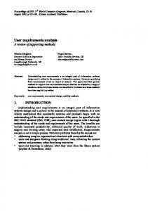
Figure 10: Top level work flow lighting model from many simultanous individual perspectives. (High resolution image at the end of document). Work flow models were developed in close collaboration between COWI and Aalborg University. Due to time available in the project the modelling work was not supported by direct involvement of ongoing activities at the consulting engineering company but indirectly by involving experienced designers and their experiences.
12.6/28.11/22.9/4.9.2000
20/29
pc,jeo,raa,ks
6.2
SEQUENCE MODELS
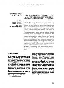
Figure 11: Detailed light design sequence model Sequence models were developed in close collaboration between COWI and Aalborg University. Due to time available in the project the modelling work was not supported by direct involvement of ongoing activities at the consulting engineering company but indirectly by involving experienced designers and their experiences. 6.3
ARTEFACT MODELS
Artefact models show the physical and virtual objects created to support the work, along with their structure, usage, and intent. The artefacts may be be (META) information containers and methods for their handling, tools to control and create other objects as well as tools to support commuinication and application software access. 'Consolidated artefact models show how people organise and structure their work from day to day' (Beyer, sid. 178). They show common organising themes and concepts used to pattern the design team work. The sequence models are complemented by the artefacts models to show how the design artefact is manipulated and with which tools. They also help to reveal the design intent
12.6/28.11/22.9/4.9.2000
21/29
pc,jeo,raa,ks
and how the team, groups and persons thinks about their work. Use real data and cases during artefact model construction. Try a similar case and compare artefact use. Remember that the artefacts shall support communication as well as possible. We do not have time to make a detailed study of many cases and then consolidate the outcome but merely to come to solution examples and document how the work can be done in future improvement of DIVERCITY. Sequence models show design intent and the work flow models show how these intents are achieved (strategies for organising work) (Beyer, sid 197). Example on DIVERCITY Artefact groups - Supplier information - Requirements from authorities - Other public information - Communication tools - Firewalls - Analysis and simulation programs - Product and process models - Process manager Artefacts may have properties like - Personal/Shared - Divercity-specific/general - Synchronous/asynchronous - Access rights, in use? - Access level - Identification, text, icon Artefact investigation (sub studies, consolidation) -
what characterises different persons/specialists in the designers time (culture/organisation, background, roles, type of work) (user models contribution) which artefacts do I need and how will I adapt for my/our personal/group use how will I/we structure the artefacts (tools) used similar artefacts can be grouped after intended and/or real use (project focus) are the artefacts personal (role/specialist dependent) or shared or both is it possible to group some personal/specialist artefacts as shared identify characteristics and parts of the listed artefacts (used in which context, found and accessed how, visual appearance, doing what) identify common and special characteristics for groups of artefacts (metaphores - search, manipulate information, wrap results, broadcast
12.6/28.11/22.9/4.9.2000
22/29
pc,jeo,raa,ks
-
-
findings, who is present, preference settings, positioning in VW, navigation in VW, product/process/tools, DIVERCITY specific, application specific, group specific, specialist specific, meta tools, personalisation possibilities, …) identify artefact importance (artefact hierarchy, … ) what should the artefact remember. (between projects, within with regard to time, context, … ). Stored where in VW. alternative artefacts or usage for the same activity alternative activities with use of same artefact. look for potential problems and changed design intent if you try to replace an existing artefact with a 'better' one. (e.g. catalogue handling dependent of presentation media vanishes in favour for recipes for container creation, catalogue search mechanisms more based on provider than user requirements) does the artefact support communication well enough (enhancements)
Steps according to (Beyer) sid 183 - 'Group the artefacts models by the role they play in the work - Identify the common parts of each artefact. Identify the intent and usage of each part - Identify common structure and usage within each part. Identify breakdowns. - Build a typical artefact, showing all the common parts, usage, and intent, and showing how they are presented where relevant. Show breakdowns' Properties of VW spaces (see also Work Flow models) - how are physical and VW organised today (reflects how work is done today - information containers, design tools, communication tools). - Which are the main constraints today in the work space. (study 2-3 cases) - types of spaces and sub-spaces (sub processes - pre/post) functionality. Which types of activities are supported (design related - sketch, analyses, synthesis, review, brainstorm, case retrievals, and collaboration/communication related - space and time positioning in VW, notes areas, annotation possibilities, states/alternative states storage, ….) - personal VW spaces display of and access to individual information containers - specialist VW spaces layout and form (alternatives) - group VW spaces layout/form (alternatives) - product (the design artefact) representation access in VW. Degree of mixed reality. - access to external applications and information resources - communication support (degree of design team member presence avatar/video/physical, communication tools, shared design tools, communication languages, private group spaces, memory functions of
12.6/28.11/22.9/4.9.2000
23/29
pc,jeo,raa,ks
the VW,….)
Figure 12: Principle VW layout with 'dimensions' and 'artefacts'.
7.
INITIAL GRAPHICAL USER INTERFACE AND VW SPECIFICATIONS
The Virtuial Workspace will contain models of -
VW (form, function, usage context) that hosts actors (user models), product (design artefact models), access to product model process (design process and cultural models, access models to external applications including information resources and individual information) tools (DIVERCITY specific artefact models and access to these).
All models above must be consistently identified in the different appearances of the VW:
12.6/28.11/22.9/4.9.2000
24/29
pc,jeo,raa,ks
The artefact models provides basis for graphical user interface. The main requirements on the GUI are - same appearance/form and functionality of artefacts in different VW realisations (also under combinations of different media and geographic distribution) - consistent grouping of artefacts in different VW access spaces - consistent naming and iconic representation (text/icon or text) of artefacts At his stage we have not made definitions of access modes that VW can provide. This must be done in collaboration with system developers, GUI designers and end users. Possible VW access modes may be 1. 2. 3. 4.
near reality access to the design artefact (building or part of building) representation (Virtual Building) access and handling of DIVERCITY tools and other tools/systems linked into the VW other than room metaphors for access of artefacts and information in VW (clouds, surface sections in multidimensional data collections etc.) combinations of 1-3
Figure 13: The Work Models forms the basis for design of the user interface to the Virtual Workspace, VW. We can distinguish three main access controls - DIVERCITY specific tools, Application systems access, and Design artefact (building). ….)
12.6/28.11/22.9/4.9.2000
25/29
pc,jeo,raa,ks
8.
THE NEXT STEPS. INTERFACE DESIGN AND IMPLEMENTATION.
In this paper we have given examples on conceptual work models developed in collaboration with end users. Work flow and sequence models have been produced. Detailed artefact models will be further developed during the interface design. Continuous testing against users will be performed during the interface design. System implementation work can e.g. use Extreme Programming techniques (Extreme programming) (from experiences of programming in SmallTalk). The technique summarises some of the ruling guides used in (Multimedia) system development. -
re-write code (e.g. extraction of codes to new method in OO environment) continuos testing with new versions with end user participation work in pairs to raise quality use automatic testing procedures (encourage revision activities) do not write more general code than is necessary for the moment (controversial statement)
The interface design is governed by for example The Eight Golden Rules, Shneidermann, 1998): -
Strive for consistency sequence of actions in similar situations, identical terminology in menus, prompts etc., Enable frequent users to use shortcuts Offer informative feedback for every user actions there should be system feedback. Design dialogs to yield closure sequences of actions should be organized into groups with a beginning, middle, and end. Offer error prevention and simple error handling to prevent serious errors (e.g prefer menu selection to form fillin), minimize retyping forms,.. Permit easy reversal of actions Support internal locus control operators should be in charge (no surprises, difficulty to obtain information,..) Reduce short-term memory load human short-term memory handles 7 +-2 chunks.
Also Usability testing methods shall be defined as well as typical user test cases that will be used as design of the Virtual Workspace progresses. (Löwgren, 1996), (Nielsen J., Mack R., 1994), (Norman D A, 1988), (Participatory Design, 1993), (Raskin J, 2000), (Readings in Intelligent User Interfaces, 1998), (Shneiderman, B.,
12.6/28.11/22.9/4.9.2000
26/29
pc,jeo,raa,ks
1998) , (Suchman Lucy, 1987), (User Interface Desig, 1998). 6.
Figure 14
9.
Detailed light design (extract). Action taken and corresponding artefacts used today.
WORK PLAN PROPOSAL AS OF THE AALBORG MEETING SEPTEMBER 4-5, 2000 1) Documentation of existing DIVERCITY tools with regard to interface/functionality, integration to other tools and underlying models/semantics. 2) Definition of DIVERCITY models and functions and the relation between DIVERCITY and product models and application systems 3) Agreements on incremental prototyping procedures in a distributed environment 4) Set up of distributed design environment. Tools selection. 5) Outline of general DIVERCITY top level interface for the 'single system architecture'. Top level functionality. Communication and control areas.
12.6/28.11/22.9/4.9.2000
27/29
pc,jeo,raa,ks
6) 7) 8) 9) 10) 11) 12) 13)
10.
Input from the three User requirements groups (Client Briefing, Design Review, and Construction Planning). Documentation of Work Models for example according to 5.4 'Contextual Design' and UML notations. Functional Interface proposals for the different use cases with detailed examples for chosen sub-cases. Mapping of use sub-cases interfaces to underlying system structure and functionality Detailed interface layout proposals for the use cases Revision of DIVERCITY system structure Implementation of use sub-cases Usability test of implementations. Heuristic evaluations. GOTO 9
REFERENCES
Beyer H, Holtzblatt K, 1998, Contextual Design. Defining Customer-Centered Systems. Morgan Kaufmann Publishers, San Francisico. (472 pp) see also http://www.incent.com/CDP.html Christiansson P, 1999, " Properties of the Virtual Building". Proc. of the 8th International Conference on Durability of Building Materials and Components, May 30 June 3, 1999 Vancouver, Canada. http://it.civil.auc.dk/it/reports/r_cib_vancouver_1999.pdf Divercity, 2000, Deliverables 2,3,4. User Requirements – Stakeholder Perspectives. Use Cases – New Process Model Definitions. Chapter System Architecture – Software and Hardware. August 7, 2000 (76 pp.) Christiansson P, 1992, Dynamic Knowledge Nets in a changing building process. Automation in Construction , Vol 1 nb 4 , March,1993), Elsevier Science Publishers B.V. (pp 307-322). Lindemann. J, 1996, Low Cost Distributed VR. KBS-Media Lab, Lund University. http://it.civil.auc.dk/it/reports/vrlindemann/lcdvr.html Extreme Programming. http://www.extremeprogramming.org http://www.c2.com/cgi/wiki?ExtremeProgrammingRoadmap. Extreme Programming Roadmap http://www.c2.com/cgi/wiki?DesignPatterns. Design Patterns Beck K, 2000, "Extreme Programming Explained: Embrace Change",
12.6/28.11/22.9/4.9.2000
28/29
pc,jeo,raa,ks
http://cseng.aw.com/bookdetail.qry?ISBN=0-201-61641-6&ptype=0 Löwgren J., 1993, Human-computer interaction. What every system devloper should know. Studentlitteratur. Lund Sweden. (134 pp). Modin, j, 1995, "COOCOM, New ways of using Information Technology for buildings design and management". (COOperation and COMmunication in the building process). KBS-Media Lab, Lund University. (29 pp.) http://www.it.civil.auc.dk/it/reports/coocom1_6_1995.pdf Mumford E., 1993, The Participation of Users in Systems Design: An Account of the Origin, Evolution, and Use of ETHICS Method. in Participatory Design. Principles and Practices. (eds: Schuler D., Namioka A.). Lawrence Erlbaum Associates, Publishers. Hillsdale, New Jersey. 1993. (319 pp.) (pp. 257-270). Mumford E., Henshall D., 1979, A participative appraoach to computer systems design. Associated Busienss Press London. (191 pp.) Nielsen J., Mack R., 1994, Usability Inspection Methods. John Wiley & Sons, Inc. New York. (413 pp.) Norman D A, 1988, The design of Everyday Things. Bantam Doubleday Dell. Basic Books Inc. New York (257 pp). Participatory Design. Principles and Practices. (eds: Schuler D., Namioka A.). Lawrence Erlbaum Associates, Publishers. Hillsdale, New Jersey. 1993. (319 pp.) Raskin J, 2000, The Human Interface. New Directions for Designing Interactive Systems. Addison_Wesley, Reading Massachusetts. (233 pp). Readings in Intelligent User Interfaces. (eds: Maybury M. T., Wahlster W.). Morgan Kaufmann Publishers, San Francisico. 1998. (648 pp) Shneiderman, B., 1998, Designing the User Interface. Addison-Wesley Longman Inc., Reading Massachusetts. (638 pp). See also http://www.aw.com/DTUI/. Simpson K. T., 1998, The UI War Room and Design Prism: A user Interface Design Approach from Multiple Perspectives. in User Interface Design. Bridging the Gap from User Requirements to Design. (ed. Larry E. Wood). CRC Press, Boston. 1998. (312 pp) (pp. 245-274). Suchman Lucy, 1987, Plans and Situated Action. The problems of human machine communication. Cambridge University Press, (203 pp) User Interface Design. Bridging the Gap from User Requirements to Design. (ed. Larry E. Wood). CRC Press, Boston. 1998. (312 pp)
12.6/28.11/22.9/4.9.2000
29/29
pc,jeo,raa,ks
Wood L., 1998, Introduction: Bridging the Design Gap. in User Interface Design. Bridging the Gap from User Requirements to Design. (ed. Larry E. Wood). CRC Press, Boston. 1998. (312 pp) (pp. 1-14).
12.6/28.11/22.9/4.9.2000
30/29
pc,jeo,raa,ks
Client -initial requirements - functional - spatial - aesthetical
Authorities - health/safety - fire
Co or Regulations
Component functional description - initial - intermediate - final
Requirements/wishes
Evaluation of principles - alternatives - possibilities
Architect - selection - aesthetic - function/use
Light manager
New version architectutre layer available
Model update request
Light model request
Pro STAFF SE
Process Manager
Set access Project manager - co-ordination - time/economy ctrl - model version - delegation rights
Light Engineer - technical functional detailed design - modelling - bill of quantities
New version engineering layer available
Light model
Light model request
Component details - specs - price - delivery time - models
New components
P
- computer model access - model update QC - new version distribution - digital repositories
Accoustic engineer Virtual Building Model - light models - HVAC models - temporal marking - version history -
Pro
Structural engineer
Update workspace
Virtual Workspace - Room model access - engineering layers access - architectural layers access - collaboration tools - general components description - component suggestions - client requirements - old cases
12.6/28.11/22.9/4.9.2000
HVAC engineer
31/29
MAIN CONTRACTOR - build
pc,jeo,raa,ks