2009 IEEE International Conference on Semantic Computing
Using a Formal Language Constructs for Software Model Evolution Samuel A. Ajila, PhD., P.Eng
Shahid Alam
Department of Systems and Computer Engineering, Carleton University 1125 Colonel By Drive, Ottawa, ON K1S 5B6
[email protected]
Department of Computer Science, University of Victoria 3800 Finnerty Road Victoria BC V8W 2Y2
[email protected] evolution using a formal modeling language constructs and graph theory to support co-evolution. Two of the top challenges identified by ECRIM [12] were to raise the level of abstraction (i.e. model evolution) and automated support for model evolution through modeling languages and tools. Support for software evolution is advancing in many ways but it is observed that almost all existing tool supports for software evolution is primarily targeted to source code and at best are software life cycle domain specific. In particular, design and modeling phases supported by UML and, UML CASE tools typically provide less support for software evolution. Since the advent of model-driven software engineering, the urgent need for more relevant techniques and tools for model evolution has increased. We are now seeing a move towards serious research attempts in model evolution. For instance, model driven architecture (MDA) allows for the separation of a platform independent model (PIM) from a platform specific model (PSM). Executable UML takes the concept of MDA further by removing the PSM from MDA and directly generates code [7]. To support executable UML, we need to fully introduce evolution at the model level. UML has notations, symbols and stereotypes to define dependency relationships, but there is no modeling technique for automated software evolution management [14]. Neither Object Constraint Language (OCL) [15] nor any other specification language provides direct support for model evolution. Recent advances include model re-factoring [7], impact analysis and change management of UML models [3], and model evolution with aspect-oriented mechanisms [16]. Earlier theoretical and foundational research works include software evolution theory and feedback by Leman et al. [9], and Madhavji et al. [10], and the work on the extension of meta-models in UML 1.3 based on stereotyping [14] and the application of action semantics to UML 1.4 [13]. The long term goal of this research is to develop techniques that will support automatic software model evolution. Specifically, our objectives are to: Develop Support for model evolution and co-evolution: A challenge here is the necessity to achieve an automatic coevolution among different representations of software models. Modification in one type of model should always be reflected by corresponding changes in other related models to ensure consistency of the software. Using language constructs to automate model evolution: A modeling language should provide a more direct and
Abstract— In this paper we present an automated support for software model evolution using a formal language constructs. For this, we extended Object Constraint Language (OCL) with actions to define a new language - CAL (Constraint with Action Language), which gives users the ability to evaluate objects change a-priori. We have added a data type, directed acyclic graph (DAG) to CAL to automate model evolution. DAG has been annotated (ADAG) with dependency weights based on an improved graph labeling scheme. Rules are designed to translate a UML model into CAL data structure (ADAG). CAL contains a small set of constructs, but is powerful enough to be used efficiently for typical software evolution management operations like impact analysis, correction, improvement and enhancement of models. A prototype tool VCAL (visual CAL), for dependency analysis of UML Class Diagrams is presented. Keywords-software model evolutiont; OCL; DAG; UML; objects change; impact analysis
I.
INTRODUCTION
Complex software system evolves over time and its architecture will change as the system meets the challenges of its environment. Empirical research shows that it is very difficult to completely predict software changes and its costs [3], [4], [10]. More time and money are spent maintaining a software system than on its original development. Also, software evolution is a change process that covers the life cycle of a software product. According to the European Research Consortium for Informatics and Mathematics (ERCIM) working group on software evolution [12] “The only way to overcome or avoid the negative effects of software aging is by placing change in the center of the software development process.” Therefore, there is need for a better and automated support for software evolution at the modeling level. Such support must be attacked from different perspectives [1], [12]: (i) basic research on techniques to understand, manage, and control software change; (ii) development of models, languages, tools, and methods to provide support for software model change; and (iii) validation of complex industrial real world software case studies [1], [2]. The aim of this research therefore is to develop an automated support for a bi-directional evolution (or coevolution) between different representations of software artifacts (models). That is, “… placing the change in the centre of the software development process. [2][12]” Specifically, we want to research the automation of model 978-0-7695-3800-6/09 $26.00 © 2009 IEEE DOI 10.1109/ICSC.2009.19
390
Authorized licensed use limited to: UNIVERSITY OF VICTORIA. Downloaded on January 15, 2010 at 12:24 from IEEE Xplore. Restrictions apply.
ordered. A Bag is a Set that may contain duplicate unordered elements. A Sequence is a Bag but the elements are ordered. These collections have an extensive set of operations for conversion, comparison, query, access, selection and iteration. In order to formally specify the internal model of the actions and operations in CAL for the tool that implements them and to verify and reason about the function and behavior of these actions and operations – we have used a specification language called TLA [8], the Temporal Logic of Actions. TLA+ is a tool for specifying the mathematical model of a system, which may have some behavioral properties. These properties can be functional and/or logical, and represent a correct execution of the system. Since TLA+ specification is a formal description of the system, tools can be applied to find errors and test the system. TLC, a TLA+ model checker [8], is a tool that is written for this purpose and is used in this paper to verify the specifications of CAL actions and operations. The CAL actions and operations can be directly specified in TLA+ but may need significant amount of space and time. To speed up this process and save space, we have used an algorithmic language that is based on TLA+ named pluscal. TLC translates specifications in pluscal to TLA+.
explicit support for software evolution. This will allow object change to be treated as a first-class entity in the language. Firstly, changes can be introduced a-priori into the system without impacting the current representation of the system under development. In this case, changes are only visible after the software modeler is satisfied with the computation of the impact of such changes. Secondly, the modeling language construct can be used to control bidirectional evolution between two different representations of the software system. Thirdly, the modeling language construct can be used as a means of verification and validation using formal methods. This way, it is not imperative to verify the entire software design model (and source code) because of a small change to the specification of the software. The roadmap for achieving this goal consists on using a formal modeling language constructs to achieve some level of model evolution. The idea is to extend Object Constraint Language (OCL) by adding actions to it. OCL is normally used as a query language for UML models. Expressions and rules in OCL can be used to identify changes in a model but cannot be used to change the state of the system. Therefore, actions (now part of UML 2.0 semantics) are needed in addition to constraints in OCL to be able to apply changes to the design model. Furthermore, we need tools for model transformation and model visualization. In this case, we have a choice between direct model manipulation or transformation language. The first choice is tedious to implement and not very good for co-evolution of models. A transformation language provides a means to explicitly represent transformation behavior and more concise description of model elements than is possible in direct manipulation. Like the model evolution language, the model transformation language must have the power to represent all types of modeling objects and behaviors including querying, modification, and navigation. For this, we use a directed acyclic graph (DAG) as a transformation language. In this case, models are treated as graphs and sub-models as subgraphs (with the same properties as a graph). Transformation rules are developed and apply as rules for rewriting graphs. Each element in the model is a node in the graph and the properties attached to the model elements are attached to the corresponding node in the graph. Rules are extracted using pattern matching techniques based on set of dependency relationships among models and model elements. The rest of this paper is organized as follows. Section 2 gives the background and related works. In section 3, we present model transformation using ADAG and in section 4, we define CAL. Section 5 presents a prototype – VCAL and we give our conclusion in section 6 II.
B. Related Work One of the early efforts to automate software evolution in UML was in 2000 when Tom Mens and Theo D’Hondt [11] proposed to extend the metamodel of UML 1.3 and based on this extension defined evolution contracts using stereotypes such as , , and etc. The purpose of these contracts was to automatically detect conflicts. Briand et al. [3] proposed an approach to perform impact analysis of UML model elements and present promising empirical results. This is the first empirical effort at automating impact analysis of UML models, but it does not address making changes to the model. The impacted elements, whether direct or indirect, are determined using impact analysis rules defined in OCL. The use of constraints, as rules, defined in OCL by itself is not optimal for impact analysis. Invoking constraints each time for tracing the change of a UML model element is not efficient. For example, select and equals have been used to query the model and to match the pattern respectively. The approach described needs to compare two complete models to detect changes. That is, the original model and the changed model are required to complete the detection process. Our approach works on just one model. As the model is changing the tool is analyzing the change, which makes the analysis process dynamic and compact. III.
BACKGROUND AND RELATED WORK
MODEL TRANSFORMATION USING ADAG
We need a transformation language for model evolution and this language must have power to represent all types of modeling objects and behaviors such as querying, modification and navigation. For this, we have used a Directed Acyclic Graph (DAG). Therefore, ADAG is Annotated DAG. In this section we present ADAG, ADAG
A. Background The OCL standard library consists of built-in types, predefined types and operations [15]. OCL collection is a predefined type. There are four collection types in OCL Set, OrderedSet, Sequences and Bag. A Set is a mathematical set. An OrderedSet is a Set whose elements are 391
Authorized licensed use limited to: UNIVERSITY OF VICTORIA. Downloaded on January 15, 2010 at 12:24 from IEEE Xplore. Restrictions apply.
labeling scheme, and rules for translating UML model to ADAG.
L(v)=LCM[label(v1),label(v2),...,label(vn)]
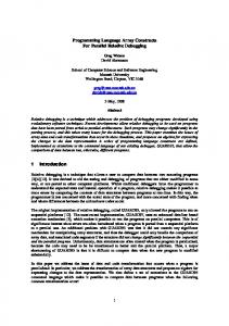
The complete label of DAG in Figure 1 using equations (1) and (2) is shown in Figure 2. All the leaves, A, B, C, D, E and M are labeled as 1. The prime numbers used are underlined. We can find the reachability between vertex Q and vertex I by simply computing the mod of the label of vertex Q with the label of vertex I as L(Q) mod L(I) = 1385670 mod 7 = 1. Therefore, vertex I is not dependent on vertex Q. We can find all the descendants of a vertex by computing the mod of each vertex's label with the label of the vertex. If the mod is 0 then a descendant of the vertex is found and vice versa. For vertex P in Figure 2 we find the following set of descendants: D(P) = { O, L, K, F, G, H, A, B, C, D, E }. So, using prime numbers from an ordered list of primes starting from 2, we can calculate the maximum number M that can be used for a label in the DAG, using the following equation: m M = ∏ pi (3) i=2 Where m is the maximum prime number used and p is the prime factor of m. The size of M depends on m. For a DAG with n vertices, m can be calculated for worst and average cases, using equation (1) as follows: Worst case, m = n – 1: In this case, a DAG is a straight line, the outdegree(v) > 0, and label of each vertex is equal to its child's label, so each vertex is multiplied by np. Average case, m = n / 2.
A. ADAG labeling Effective graph labeling scheme is very important in the use of DAG as a model transformation language. In this paper, we introduced a labeling scheme called dependency relationship weight (DRW). DRW is based on DAG-Lite [17] with improvement in label size and application to graph. In general, the following characteristics are required in a DAG labeling scheme: Ɣ Size of the label. It should be as compact as possible; Ɣ Time it takes for the queries to complete the DAG operations, for dependency analysis; Ɣ Updates should require minimal re-labeling; Ɣ Reachability: checks if one of the vertex of a DAG is reachable from (dependent on) other vertices, i.e. to find out if a path exists between two vertices; Ɣ Descendants: find all the descendants of a vertex in a DAG, i.e. which of all other vertices depend on the vertex. We formally define DAG, G, as follows, where V is the set of vertices and E the set of edges: G = (V, E, L, W), where E = (x, y) = { xy: x ∈ V, y ∈ V, xy ∈ E } such that E is a Partial order on set V L = { (l(x) ∪ l(y)) ∈ L : xy ∈ E }, l(x) is the label of x and l(y) is the label of y W = { w(x, y) ∈ W : xy ∈ E }, w(x, y) is the weight of x Total weight of v ∈ V is defined as w(v) = ¦ w(a,b), where D(v) ∈ E and is a set of descendants of v (a,b)∈D(v) We also define Indegree of a vertex as the number of edges adjacent to that vertex and outdegree is defined as the number of edges adjacent from a vertex. Ideally, for any two vertices we should be able to determine reachability by comparing only their labels. But, for a graph of more than 100 vertices it is computational expensive to calculate and extremely difficult to visually look for reachability between two distant vertices. As an improvement, our DRW used uniqueness of prime factorization – a property of prime for labeling DAG. Our approach is different and better in size than the approach used in DAG-Lite [17]. Let a, b∈̓N and LCM[a, b] as the least common multiple of a and b, the set of children of v∈ V, C(v) = {v1, v2, v3, ..., vn}, where 1 ≤ n ≤ outdegree(v) and np is the next prime from an ordered list of primes starting with 2. Then we define two equations for labeling the DAG as follows: outdegree(v) = 0 n label(v) = L(v) x np L(v) = label(vi) i=1 L(v) else
(2)
Figure 1. Sample DAG
In DRW, not every vertex in the DAG is multiplied by an exclusive prime number. In equation (1), L(v) is only multiplied by np, when it equals one of the labels of children of v and hence reduces the size of m in equation (3). This significantly reduces the number of digits in the label as compared to a similar scheme used in DAG–Lite [17], which assigns an exclusive prime number that is multiplied by the label of all the vertex's parents, as defined in equation (1). We have also improved the space for storing all the labels of the node in a DAG by assigning 1 as the label of leave vertices as compared to the DAG-Lite
1
(1)
392
Authorized licensed use limited to: UNIVERSITY OF VICTORIA. Downloaded on January 15, 2010 at 12:24 from IEEE Xplore. Restrictions apply.
with ADAG, which is also the CAL data structure, the actions and operations are used to automate dependency analysis of a UML model and can be used for impact analysis. The five action statements are createStmt, deleteStmt, addAttrStmt, createLinkStmt and deleteLinkStmt. As the names suggest, they can be used to create or delete objects or attributes and create or delete links or associations between elements. Given below are CAL production rules.
scheme, which assigns an exclusive prime number to a leave, which is multiplied by the label of all the leave's parents.
operationContext ::= operationName ( ( 'pre' id? ':' OclStmt )+ | ( 'post' id? ':' OclStmt )+ | ( 'body' id? ':' OclStmt )+ | ( 'action' id? ':' ActionStmt )+ ); ActionStmt ::= createStmt | deleteStmt | addAttrStmt | createLinkStmt | deleteLinkStmt ; createStmt ::= 'create' operation | 'create' operation 'to' pathName ; deleteStmt ::= 'delete' id | 'delete' id 'of' pathName ; addAttrStmt ::= 'addattr' id | id 'to' pathName ; createLinkStmt ::= 'link' pathName association pathName ; deleteLinkStmt ::= 'unlink' pathName pathName ; operation ::= visibility* id '(' parameters* ')' ; pathName ::= id ( '::' id )* ; visibility ::= 'public' | 'private' | 'protected' ; id ::= letter+ allowedChar*;
Figure 2. Labeled Sample DAG
B. Translating a UML model to ADAG We used the definition of DAG given in section 3 to define rules for translating a UML model to ADAG and an example of UML class diagram translation rules is given below: If V is the set of vertices and E the set of edges in the graph, m, x, y and z are model elements, and RD ∈ (Dependency ∨ Composition ∨ Generalization ∨ Realization), then
Using OCL syntax, we describe in Table 1 the informal semantic of the CAL library and CAL actions in Table 2. The word result is used to refer to the value that is obtained from evaluating the operation and the word iterate is any searching technique (e.g. depth first or breadth first, etc.) suitable for a directed acyclic graph. Post conditions are used to describe the properties of the result. Like OCL, CAL is a typed language, so we have defined a collection type, DagType, for the CAL data structure. In addition, CAL contains a library function, Dag (cf. Table 1). This function is used to create ADAG of a UML model (cf. Table 2). The operations depend and descendants check for dependency between two elements and all the descendants of an element respectively. Also, depend is used in the production rules deleteStmt and deleteLinkStmt to check the dependency, and accordingly the dependent objects are deleted or unlinked.
R1.1: Vm { (m ∈ V) ∧ ¬ (¬ m ∈ V) } R1.2: Vx,y { (xy ∈ E) → ((x RD y) ∨ (y RD x)) } R1.3: Vx,y { (x RD y) → ¬ (y RD x) } R1.4: Vx,y,z {((x RD y) ∧ (y RD z)) → (x RD z) } R1.5:Vx,y{(xRDy)∧ ((RD∈ (Dependency ∨ Realization)) → (w(x,y) = 1) ∨ (RD ∈ (Generalization ∨ Composition)) → (w(x,y) = 2)) } According to rule R1.1 model elements become vertices of the graph. Rule R1.2 states that if there is a relationship between two model elements then they become an edge in the graph. The relationship RD is described by Rules R1.3 and R1.4 as transitive and non-reflexive respectively, so by definition the graph is a DAG. Rule R1.5 assigns a selfweight to each vertex in the edge. This assignment of selfweight to the model elements is due to the couplings of different relationships among the model elements. IV.
TABLE I. Name
Semantic
DagType (data type)
inv: self.name = 'Dag{' + self.element.name + '}'
Dag (operation)
Dag is a DAG of an instance of the context. The instance becomes the root vertex, and all its dependent vertices become the child vertices in the form of a DAG.
isdag (operation)
Context Dag :: isdag() : Boolean post: result = self->type->elementType-> oclIsKindOf(DagType) = 0
CONSTRAINT AND ACTION LANGUAGE - CAL
CAL is a text based scripting language defined for the purpose of model evolution. For this, OCL is extended by adding 5 actions, 10 operations and 1 data type. Together
CAL LIBRARY
393
Authorized licensed use limited to: UNIVERSITY OF VICTORIA. Downloaded on January 15, 2010 at 12:24 from IEEE Xplore. Restrictions apply.
size (operation)
Context Dag :: size() : Integer post: result = self->iterate(elem; count : Integer=0 | count+1)
isempty (operation)
Context Dag::isempty() : Boolean post: result = Dag->size() = 0
flatten (operation)
Context Dag :: flatten() : OrderedSet(T) post: result = if (self->isdag()) then self->iterate(elem; s : s-> union(elem->asOrderedSet())) else self endif
includes (operation)
Context Dag :: includes(object : T) : Boolean pre: self->isdag() and self->~isempty() post: result = self->1contains(T) = 1
excludes (operation)
Context Dag :: excludes(object : T) : Boolean pre: self->isdag() and self->~isempty() post: result = self->1contains(T) = 0
depend (operation)
Context Dag :: depend(object parent, object : child) : Boolean pre: self->isDagType() and self->includes (parent) and self-->includes (child) post: result = ( if label(parent) > label(child) then label(parent) 2mod label(child) else label(child) 2mod label(parent) endif ) = 0
descendants (operation)
view (operation)
1 2 3 4 5 6
unlink
Context Dag :: unlink (object : P, object : C) : Boolean pre: self->isdag() and self.includes(P) and self.includes(C) body: if self->depend(P, C) 5 then self-> removeLink (P, C) and self->4setweight(null, P) and self->2relabel(P) else self endif post: result = ~self->depend(P, C)
= Deletes an element from the ADAG = Labels all the ancestors of an element = Sets the parent of an element (in this case P becomes the parent of C) = Sets the self-weight of an element in the ADAG = Removes the direct link between two elements in the ADAG = Sets the attribute of an element (in this case A is added as an attribute to C)
The complete process of using the ADAG can also be displayed visually using one of the CAL library operations, view, to let the software design or maintenance engineer decide where and what changes are to be made to the model. CAL actions, create, delete, link, unlink and addattr, are responsible for incrementing the global variable CHANGE_RATE (defined in the CAL library). CHANGE_RATE is the number of objects changed and can be used to calculate the percentage of objects that change from one version to the next [10]. Similarly create and delete increment or decrement the global variables OBJECTS_ADDED and OBJECTS_REMOVED respectively to calculate the growth rate [10], which is the difference between added and removed objects.
Context Dag :: view(object : E) : Boolean pre: self->isdag() and ~self->isempty() post: result = Dag { E }->3view()
1 = Checks the presence of an element in the ADAG 2 = Computes the mod of two labels (integers) 3 = Displays an interactive ADAG
Name
Semantic
Addattr Context Dag :: addattr(object : A, object : C) : Boolean pre: self->isdag() and self.includes(C) post: result = self->6setAttribute(A, C)
Context Dag :: descendants(object E) : Boolean pre: self->isDagType() and self->~isempty() post: result = self->iterate(elem; s : self-> depend(E, s))->flatten ()
TABLE II.
Name
CAL ACTIONS Semantic
create
Context Dag :: create (object : T) : Boolean pre: self->isdag() body: self->1add(T) post: result = self->includes(T)
delete
Context Dag :: delete (object : T) : Boolean pre: self->isdag() and self->includes(T) body: if (self.descendants(T)->size() = 0) then self->setweight(null, T) and self->2relabel(T) and self->1delete(T) else self endif post: result = self->excludes(T)
link
Context Dag::link(object: A, object: P, object: C) : Bool pre: self->isdag() and self.includes(P) and self.includes(C) body: self->3setParent (P,C) and self->4setweight(A, P) and self->relabel(P) post: result = self-->depend(P, C) Figure 3. Part of the main block of CAL specification
394
Authorized licensed use limited to: UNIVERSITY OF VICTORIA. Downloaded on January 15, 2010 at 12:24 from IEEE Xplore. Restrictions apply.
TLA (Temporal Logic of Actions) is used to specify CAL. TLA is normally used for specifying and reasoning in concurrent and reactive systems. It is a tool for specifying the mathematical model of systems behavioral properties. The language of TLC is called TLA+. Using TLA to specify CAL is necessary because OCL do not have side effect on system behavior and thus, to verify ADAG, a behavioral specification tool is needed. Also, a model checker called TLC has been developed for finding errors in TLA+ specifications. We give below an example of a part of the main block of CAL specifications (Figure 3). The way this work is after translating CAL source into TLA+, TLC model checker is executed on the resulting specifications. TLC first checks the initial state (defined as Init) and the next state (defined as Next). TLC initializes all the global variables in the initial state. Then it starts to generate and execute all the states defined in the Next state. While executing these states, TLC checks all the type invariants (defined as TypeInvariant) and reports an error if any one of these types is violated. TLC also checks and reports any deadlock in the states. V.
REFERENCE [1] Samuel A. Ajila, Software Maintenance: An Approach to impact Analysis of Objects Change, International Journal of Software - Practice and Experience, Vol. 25(10), (1995) , pp. 1155 – 1181 [2] Samuel A. Ajila and Badara A. Kaba, Evolution Support Mechanisms for Software Product Line Process, The Journal of Systems and Software, Volume 81, Issue 10, October 2008, pp 1784-1801 [3] L. C. Briand, Y. Labiche, L. O'Sullivan, M. M. Sówka, Automated impact analysis of UML models, The Journal of Systems and Software, Vol. 79, Issue 3, March 2006, pp 339352 [4] Stephen G. Eick, Todd L. Graves, Alan F. Karr, J.S. Marron, and Audris Mockus, Does Code Decay? Assessing the Evidence from Change Management Data, IEEE Transactions on Software Engineering, Vol. 27, No. 1, pp 1 – 12, January 2001 [5] Franks Greg, 1999. Performance Analysis of Distributed Server Systems. PhD thesis, OCIECE-00-01, Department of Systems and Electrical Engineering, Carleton University, December 20, 1999. [6] Gray J., Lin Y, and Zhang J., Automating change evolution in model-driven engineering, Computer, Vol. 39, No. 2, Feb. 2006, pp 51-58 [7] Lukasz Dobrzanski, Ludwik Kuzniarz, An approach to refactoring of executable UML models, Proceedings of the 2006 ACM Symposium on Applied computing, pp 12731279, 2006 [8] Lamport, L. 2003 “Specifying Systems: the TLA+ Language and Tools for Hardware and Software Engineers,” AddisonWesley Longman Publishing Co., Inc © 2003. [9] M. M. Lehman and J. F. Ramil, Rules and Tools for Software Evolution Planning and Management, Annals of Software Engineering 11, pp. 15-44, Kluwer Academic Publishers, The Netherlands 2001. [10] Madhavji, N. H., Fernandez-Ramil, J., and Perry, D. “Software Evolution and Feedback: Theory and Practice," John Wiley & Sons © 2006. [11] Tom Mens and Theo D'Hondt. “Automating support for software evolution in UML,” Automated Software Engineering Journal, 7(1): p 39--59, February 2000. [12] Mens, T.; Wermelinger, M.; Ducasse, S.; Demeyer, S.; Hirschfeld, R.; Jazayeri, M., Challenges in software evolution, IWPSE-05, pp. 13-22, 5-6 Sept 2005. [13] Object Management Group (OMG) Inc, “Semantics of a Foundational Subset for Executable UML Models,” OMG © 2005/2006, RFP [14] Object Management Group (OMG) Inc., “Unified Modeling Language Specification”, UML 2.0, Officially Adopted June 12, 2003. [15] Object Management Group (OMG) Inc., “OCL 2.0 Specification Version 2.0”, OMG @ 2005 [16] Ubayashi, N.; Tamai, T.; Sano, S.; Maeno, Y.; Murakami, S., Model evolution with aspect-oriented mechanisms, Proceedings for the IEEE Eighth International Workshop on Principles of Software Evolution, 2005, pp. 187-194 [17] Gang Wu, Kuo Zhang, Can Liu, Juan-Zi Li, Adapting Prime Number Labeling Scheme for Directed Acyclic Graphs, Lecture Notes in Computer Science Vol. 3882, pp 787-796, Springer-Verlag, 2006.
CONCLUSION
In this paper, we have presented an approach using a formal language constructs to support software model evolution. Our approach provides a more direct and explicit support for software evolution and allows object change to be treated as a first-class entity in the modeling language. The constraint and action language (CAL) can be used to manage bi-directional software evolution. Our transformation language (ADAG) provides a means to explicitly represent transformation behavior with concise description of model elements that is possible with direct manipulation. Not shown in this paper (for lack of space) are the specifications of eight CAL operations: isempty, isdag, includes, excludes, depend, descendants, flatten and view and six CAL sub-operations: relabel, setweight, CheckDependency, Label, LCM and CheckCycle. For example, the complexity of the CAL operations descendants for worst case and average case is O(n) and depend, have worst case and an average case of O(n) and O(1) respectively. All these operations and actions are verified by the TLC model checker. We have also developed a prototype VCAL that generates dependency and performs impact analysis with little input from users. We are currently developing mapping rules and specifications for UML state machines. We are also exploring the possibility to autogenerate and verify CAL interpreter from CAL specifications using compiler-compiler principle. ACKNOWLEDGMENT This paper is a part of research work supported in part by NSERC (Natural Sciences and Engineering Research Council of Canada) discovery research grant number RGPIN/250271
395
Authorized licensed use limited to: UNIVERSITY OF VICTORIA. Downloaded on January 15, 2010 at 12:24 from IEEE Xplore. Restrictions apply.