J. Design Research, Vol. 10, No. 3, 2012
Using a semiotic classification to characterise objects involved in collaborative design Jean-François Boujut* G-SCOP, Grenoble INP, UJF, CNRS – 46, av. Félix Viallet – 38031 Grenoble, France E-mail:
[email protected] *Corresponding author
Onur Hisarciklilar Department of Mechanical Engineering, McGill University, 817 Sherbrooke St. W., Montreal, QC, Canada E-mail:
[email protected] Abstract: This paper addresses the problem of expression and sharing of domain-specific constraints and knowledge in engineering design. Pierce’s theory of signs allows understanding why purely graphical 3D CAD systems partially fail to support design teams during design review meetings and more generally during collaborative design episodes. This theory can help us to go further in analysing annotation systems as symbolic systems of signs and we draw a parallel with the 2D standard drawing system, as they have the same semiotic nature. We show that semantic annotations can be considered to improve the semiotic richness in 3D CAD representations. A case study illustrates the need for cooperation support to multidisciplinary design teams. In this paper, we support the idea that future design tools should integrate both symbolic and iconic types of representations so that the designers could freely build shared representations taking advantage of the whole symbolic-iconic spectrum. We propose future developments reconciling the graphical precision of 3D digital models with the semantic richness of symbolic systems of signs. Keywords: semantic annotation; design communication; asynchronous collaboration; semiotics; engineering design. Reference to this paper should be made as follows: Boujut, J.F. and Hisarciklilar, O. (2012) ‘Using a semiotic classification to characterise objects involved in collaborative design’, J. Design Research, Vol. 10, No. 3, pp.155–169. Biographical notes: Jean-François Boujut is Professor of Engineering Design at Grenoble Institute of Technology in the Industrial Engineering school. He earned his PhD in 1993 and his Habilitation in 2001. His research interest is on design communication and collaborative aspects of innovative design including tools for managing informal information and sharing knowledge. He teaches creativity and innovation methods and collaborative engineering aspects. Onur Hisarciklilar is currently a Postdoctoral Fellow at McGill University, Canada. He received his PhD from Grenoble Institute of Technology, France in 2008. He participated in several research projects in collaboration with automotive and aerospace industries. His research is focused on PLM systems, process improvement and design collaboration in new product development.
Copyright © 2012 Inderscience Enterprises Ltd.
155
156
1
J.F. Boujut and O. Hisarciklilar
Introduction
Digital 3D product representations are widely used today in engineering for purpose of communication during design meetings and serve as a common platform for the participants in their effort to reach a mutual understanding of the situation they are facing. These 3D representations are supported by visualisation tools that provide very sophisticated functionalities for the manipulation of the geometry, the extraction of measurements, and sometimes the recording of textual notes via mark-ups. Recent technologies provide holographic viewers to designers for a better rendering of the realistic character of the digital object. Over time, the representation tools tend to provide more and more sophisticated effects that allow a visual experience of the object that is as close as possible to the visual experience one could have of the real object. If we use the metaphor of map and territory, we can argue that this trend can be compared with a situation where a traveller would want his map to look like the territory as closely as possible. But the map is obviously not the territory itself. Its function is to help the traveller in finding his/her way in the real world by reflection, inference, deduction, etc. Moreover, the map can help two travellers build an agreement on the safest route to follow. The map then becomes a communication medium, just like 3D representations of the product can become communication media in design review meetings. Depending on their domains of expertise, habits, etc., stakeholders have different design practices and different ways to represent the output of their design work. However, common ways to represent the design are also required in cooperative design situations, where discussions, debates and argumentation can occur, and where design participants can share their knowledge about the current design situation and discuss the design solutions. Cooperative design work occurs in synchronous situations, for example in design meetings, where participants discuss face-to-face or via videoconferencing tools. There is also an increasing need for asynchronous cooperation today, due to the geographic distribution of design teams. Similarly to maps that contain additional information that cannot be derived from the pure geometry, there is a need to provide a richer semantic support to designers. The geometry will never be sufficient in itself to convey complex meanings related to complex multidisciplinary design problems and contexts. In this paper, we propose to analyse the design representations as signs and consider the symbolic/iconic nature of these signs depending on the nature of the representation. One way to introduce some richer and complex content into design representations is to go back to the traditional, yet poorly studied, annotation practices. Annotations and their use for supporting knowledge elicitation are not new. According to Wolfe (2002), medieval scholars annotated margins of manuscripts to create a sort of forum for sharing knowledge, debating readings of a text, and illuminating different reading strategies. Annotations were so important in reading practices that books were often transcribed along with their annotations. The main enabler of that practice was the fact that the same copy of a document was shared by multiple readers. Wolfe (2002) then demonstrates that there is a similarity between that practice and modern computer-supported annotation practices. Today, the collaborative document sharing tools offer multiple participants the possibility to collaborate through annotating the same virtual documents. That situation offers major advantages to virtual communities, such as supporting collaboration between members of distributed teams (Baber et al., 2005), collective annotation of textual
Using a semiotic classification to characterise objects
157
documents to improve reading time (Marshall et al., 1999), or stimulating decision making processes (Guibert et al., 2005). The emergence of digital documents has also changed annotation practices in engineering design. Virtual documents are very frequently used today between designers to support design work, thanks to network-based systems that offer some functionality for sharing and annotating these documents. The positive effect of annotations on knowledge elicitation and team coordination have been already reported (Boujut, 2003). Based on the classification of Pierce’s semiotic elements, the aim of this paper is to show that the actual trend of CAD systems, that is to rely almost exclusively on 3D graphic geometry, does not fulfil the requirements for a good communication among designers. We are looking here for some paths that reunify semantic contents (especially for supporting the argumentative side of design activity) expressed under various forms, from textual (or conceptual) to pure iconic representations. We discuss how annotations should be used in 3D digital worlds in order to support design communication. We will first introduce Pierce’s semiotic elements and show how these semiotic elements can be found in various representations used by engineers. We conclude these sections by a classification of the classical types of representations used in engineering design with regard to their semiotic characteristics. In a second part we introduce a case study that illustrates the use of textual elements as addition to graphical elements in a design team for supporting decision making and dissemination of decisions in the design team. We then extend this to a more general category of annotation and introduce the concept of semantic annotation. We discuss this concept in the context of engineering design and support the idea that the concept of semantic annotation can be used to integrate textual elements into graphical semiotic elements in a kind of symbolic/iconic continuity. Design teams could then benefit of a wider communication support for expressing their ideas, recording decisions or eliciting some underlying rationale.
2
On the use of icons and symbols in engineering design
2.1 Introduction to Pierce’s semiotic elements The philosopher and mathematician Charles Sanders Pierce (1839–1914) proposed a three-level typology of signs that is distinguished by a phenomenological categorisation based on the way the sign (or signifier) denotes the object (signified, which the sign refers to): icons, symbols and indexes. For Pierce ‘signhood’ is a way of being in relation.1 In our engineering design context this allows the study of the systems of representations (i.e., technical drawing standards, specific technical languages, etc.) as relations between objects, people and objects, or people and people through objects, etc. For our purposes here, we will stress on the differences between icons and symbols as particularly relevant for analysing design representations and the role they play in an engineering process. For Pierce, an icon is a sign where the signifier is perceived as resembling or imitating the signified (looking, sounding, feeling, tasting or smelling like it), in other words being similar in possessing some of its qualities. A photograph of an apple, for instance, is iconic, as it refers to it by having the same dimensional proportions, shapes, rendering and colour. Thus, the relationship between these two objects is physical and natural rather than intellectual and cultural.
158
J.F. Boujut and O. Hisarciklilar
On the other hand, a symbol is a sign where the signifier does not resemble the signified; it is, on the contrary, fundamentally arbitrary or purely conventional so that the relationship must be learnt. The language is the most typical example of symbolic signs. Words defined in a given language do generally not have any resemblance with the objects that they represent (except may be for the Chinese or Japanese alphabet). For example, the word ‘apple’ does not contain any physical characteristic of the object of apple. And obviously, one should learn the significance of that word in order to make the relationship. Pierce adds that a signifier is never purely symbolic or iconic. It is always a mix of these characteristics with different proportions. For example, even a photograph can contain some conventions required to be correctly interpreted. A sign can also be a combination of several signs of different types. The ‘no smoking’ sign is a typical example of this. The representation is composed of a drawing representing a cigarette (which is rather iconic), circled and crossed out by a red line, which is a very conventional way to represent an interdiction (see Figure 1). Figure 1
A typical no smoking sign combining symbolic and iconic type of sign (see online version for colours)
In addition, Pierce stresses that a sign is an irreducible triadic relation between the sign, the object and the interpretant (piece of knowledge that allows recognition of the sign-object relationship). One cannot reduce the relationship to pairwise links. For example, there cannot be a correspondence sign-object irrespectively from the interpretant or a correspondence sign-interpretant irrespectively to the object and so on. Therefore, if one considers that in engineering design the external representations (i.e., CAD models) act as signs, the object stands for the final product and the interpretant refers to the meaning embedded in the designers’ minds. Then it appears that the implicit premise underlying the modern CAD tools is that the interpretant should exclusively refer to the qualities of the object itself (e.g., its dimension, weight, etc.). In that case, following Pierce’s typology, the sign’s way of denoting the object is iconic. However, in the past, other graphical languages did not take this premise as granted and therefore they were conveying richer meanings. This is what we will present in the next section.
2.2 Drawings and standard notations as symbolic elements The emergence of a standard 2D projection system of representation [thanks to Monge and Heather’s (1851) descriptive geometry] is a consequence of the development of the
Using a semiotic classification to characterise objects
159
industry (Lavoisy, 2000). This was triggered by several evolutions, examples include an increasing complexity of products, lower tolerances and therefore an increased quality of products, emergence of new production technologies, or segmentation of expertises related to design and manufacturing [formalised later by Taylor (1911)]. These changes have requested the use of more accurate representations, containing more information (e.g., about tolerances or manufacturing technologies), which could be an effective and unambiguous way to communicate design information, especially between designers and manufacturers. Figure 2
Example of a 2D drawing
160
J.F. Boujut and O. Hisarciklilar
Thus, the 2D drawings have evolved to become progressively highly conventional and symbolic (see Figure 2). The main advantage of these drawings is that they are good and accurate communication vehicles thanks to their standardised form and drawing rules. The symbols can be considered as a local language used by the various stakeholders of the engineering process to convey specific technical information. Note that there is no 3D equivalent representation system that supports this kind of information today. Therefore, 2D drawings are still preferred in many design situations. The symbolic nature of these representations requires specific knowledge (therefore learning) for their interpretation. The interpretant requires richer cognitive inference related to (and consistent with) the level of complexity of the domain knowledge involved. The use of symbolic type of signs seems to be necessary when the information embedded in the representation is very complex and involves deep technical knowledge. Symbolic elements appear to be the vehicle of complex technical meanings.
3
From 2D drawings to 3D digital models: iconic and symbolic nature of design artefacts
Some typical design artefacts can be analysed according to Pierce’s theory of sign. For example the 3D CAD model of Figure 3 represents a view of a sub-assembly of a truck chassis. It is typically the kind of model that is shared among design teams during detailed design phases. As we have seen in the introduction, the aim of this 3D representation is to look like as closely as possible to the mechanical components it represents. The underlying premise being: the closer we are to the real geometry, the less we take risks when interpreting the geometry. We have seen in section 2.1 that this type of representation tends to be iconic as the project of the designers is to make to the model as close as possible to the object (make the map as close as possible to the territory). Figure 3
3D model of a sub-assembly (see online version for colours)
Using a semiotic classification to characterise objects
161
Sketches are another example of artefacts frequently used by designers. Sketches, although they are rather iconic, contain usually more conventions than 3D CAD representations. Often, some areas in sketches follow some technical drawing rules (for example hatchings, doted lines, etc.) or specific conventions related to a domain of expertise. The interpretation of these sketches requires specific knowledge, related for example to a domain of expertise, a community of practice (e.g., electronic), or the context in which the sketch has been created. In addition, sketches are often used during conversation in order to support a discourse. In these cases, the message the sketch conveys often remains understandable only within the same context (Figure 4). Figure 4
Example of an annotated sketch
Source: http://www.ekran.org/ben/wp/2011/system-sketch-and-backgroundsubtraction/
As we have seen in Section 2.2, technical drawings and standard notations have a symbolic nature as they are used to convey information from one context to another (from the context of the design office to the subcontractor for example). The symbolic system is used here to ‘de-contextualise’ the message, so that the drawing acts as a mediator between two actors of a design chain. The symbolic nature of the representation allows this transfer accomplished with a minimum of information loss, contrary to the sketches which are less codified and whose aim is to remain local. Annotations, as we defined them in an earlier paper (Guibert et al., 2005), have a communicative function. Although annotations act in a smaller and less codified arena than 2D drawings, their nature is also mainly symbolic. If we go back to Pierce we notice that symbols are the preferred type of signs that are used in the most sophisticated class of sign, the one that refers to the argumentative communication. This is typical in collaborative activities where the interpretant is mostly using argumentation as communication mode. The symbolic nature of the annotation is therefore inherently linked to its utility, i.e., communication. As for the drawing system the annotations allow
162
J.F. Boujut and O. Hisarciklilar
a de-contextualisation of the information and convey meaning from one context to another (an annotated model can be reused in various design meetings for example). Figure 5
Status of the design artefacts as signs in Pierce’s theory
Figure 5 summarises the relative positions of the various types of design representations (considered as signs) along a symbolic-iconic axis. We can see that 2D and 3D representations are rather complementary and 2D representations are at the same level as the graphical annotations. In the following, we present a design case, based on our observations in a French leading industrial vehicle company. We will point out the need of the designers to enrich the representations they share with symbols in order to improve communication.
4
A design case involving symbolic and iconic artefacts
In this section, we particularly stress on the information sharing in the asynchronous and synchronous phases of the process. We describe a design episode that occurred during the detailed design phase of a truck chassis. This design episode is made of design meetings and asynchronous design phases where the stakeholders work in parallel. In this section, we will see how designers naturally introduce and mix of elements of language and graphic elements for sake of clarity and storage of decisions during the design process.
4.1 The design team The cross-domain team we consider here is led by an architect. With his high technical level, the architect coordinates the design activities of an entire sub-system of the truck. He communicates with the design team during asynchronous phases of the project in order to assess geometrical conformity and also manages the design reviews. The actor called project management support (PMS) works with the architect and is in charge of short-term operational management of the project. During the asynchronous phases, he manages and communicates information about the studies in progress (such as deadlines, types of vehicles impacted by each design task, etc.). He is also in charge of the design review minutes. The designers are technical stakeholders who develop solutions within the CAD environment. Other stakeholders, called industrialists are experts from different domains (manufacturing, in-service, quality, etc.). They participate to the design review meetings in order to evaluate the design solution with regard to their specific knowledge.
Using a semiotic classification to characterise objects
163
4.2 An asynchronous design phase During the asynchronous phase the designers develop the technical solutions of their respective subsystems. Solutions are developed mainly according to the individual decisions of the designers on the basis of their own knowledge on the context and decisions taken during the previous meetings. Although this is an individual activity, the designers need occasionally to collaborate with the other stakeholders, especially with other designers and the architect. Communication is free and informal (face-to-face meetings, telephone calls or e-mail exchanges). When the CAD models are completed, the architect integrates the instances into the shared CAD environment. In other words, from that particular moment, the model of the ongoing solution becomes accessible to the other actors until the next design review meeting.
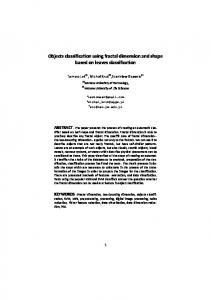
4.3 A synchronous design phase: the design review meeting The design reviews meetings were originally dedicated to validation. However, the stakeholders took the opportunity of these regular meetings to set up real co-design sessions, as there was no formal place dedicated to an interdisciplinary collaborative session in the general design process agenda. This is then a place where key decisions and their rationale are made explicit and the design review meetings become the unique place where participants could exchange arguments about design solutions and make new propositions. During a typical design review designers present the current state of the design solution they produced. It is an oral presentation where they give all the information that cannot be inferred from the analysis of the CAD model (rational behind the design choices, key points of the solution, etc). Then, the participants discuss the solution, domain-specific rules are made explicit and the ongoing solution is evaluated with regard to these rules. Figure 6
An annotated screenshot in a design minute (see online version for colours)
164
J.F. Boujut and O. Hisarciklilar
The design minute is built simultaneously by the PMS. When a decision is made or an action is decided, the PMS takes a screenshot of the 3D view and takes note of the decision by annotating the screenshot. Finally, the design minute is transformed into a pdf document composed of a series of annotated screenshots. The annotations are of textual nature, anchored to a point on the image by an arrow (Figure 6). After the review, this document is shared and remains accessible to all the participants until the next meeting. This design case illustrates several important points: Firstly, the 3D CAD constitutes the main mediating artefact that enables the discussions between the participants, secondly the participants express domain specific rules, evaluate the solution with regards to these rules and build a common understanding, thirdly, participants find effective to add textual annotations to the 3D CAD screenshots during the review. This brief case study shows the emergence of textual annotations in the context of a design review meeting. This observation leads us to pay closer attention to the concept of semantic annotation and them within the framework of engineering design.
5
Properties and the symbolic dimension of semantic annotations
5.1 What is a semantic annotation? Semantic annotations can be described as annotations that are interpretable (or reusable) by a human being in a given context. In the Semantic Web domain, semantic annotations are intended primarily for use by machines to identify concepts and relations between concepts in documents to create ‘intelligent documents’, a document which ‘knows about’ its own content in order that automated processes can ‘know what to do’ with it (Uren et al., 2006). The Semantic Web annotation frameworks, such as Annotea (Kahan and Koivunen, 2001) or CREAM (Handschuh and Staab, 2002) are intended to relate terms in a web document to an ontology, to both abstract concepts and instances of abstract concepts, in order to remove any ambiguity about the terms. Semantic Web annotation brings two kinds of benefits to the information systems, enhanced information retrieval and improved interoperability. Information retrieval is improved by the ability to perform searches, which use ontologies to make inferences about data from heterogeneous sources. Interoperability is particularly important for organisations which have large databases often in different proprietary formats that do not easily interact. In these circumstances, annotations based on a common ontology can provide a common framework for the integration of information from heterogeneous sources. Semantic annotations dedicated to human utilisation, on the other hand, can be defined by their goals. The goal of an annotation in this context is the relation between object (information) and the action (the effect of the information). Zacklad (2006) argues that annotations can either take the form of a proposal that can be integrated into the main semiotic product or can be designed to express criticisms or to raise questions without being intended to remain a part of the main product. Marshall (1997) defines six types of annotations in collaborative reading according to their goal: annotations as procedural signals, annotations as place markings and aids to memory, annotations as in situ locations for problem-working, annotations as a record of interpretive activity,
Using a semiotic classification to characterise objects
165
annotations as a visible trace of the reader's attention, and annotations as incidental reflections of the material circumstances. Although the exact definition of an annotation is still controversial, it is possible to give a basic definition of the concept of semantic annotation by listing its properties and particularly by clearly distinguishing it from the concept of document. Documents are graphical or textual representations (a report, a CAD model, etc.), created to accomplish a task in a given context. Although there may be other documents that can be used complementary to the main document, any document can be interpreted independently from other documents. In contrast, annotations are attached to a document and can be interpreted only in the context of this document. Although they have this contextual relationship with the document, the goal behind their creation may differ from the goal of the entire document. Annotations are not all the time easy to detect especially when the documents are under construction.
5.2 Properties of semantic annotations in the context of engineering design The general properties of annotations in engineering design can be summarised as follows (Guibert et al., 2005): •
An annotation has a different nature from the document on which it is attached to (for example representing non-geometrical information on a geometrical CAD object).
•
The target is the object containing information that the annotation refers to. It can either be a document, (textual or graphical), a part of a document (a paragraph, a word or a par of an image), a collection of documents or another annotation. Annotation lifetime is always shorter than the target lifetime.
•
The content of an annotation is the information the annotation conveys. This can have various forms (such as textual or graphical) and can be situated in or out of the target document (such as a hyperlink pointing out an external document).
•
The anchor of an annotation is the point onto the document, where the annotation is attached. Note that the form of the anchor of an annotation can also contain a semantic meaning.
•
The sphere of influence of an annotation is defined by its personal or public status, i.e., whether the originator and the user of an annotation are different. The form of an annotation is closely related to its sphere, as they often require more effort from its creator to become interpretable to its users.
As we have seen, an annotation is only valid in the context of the document it is attached to. The document constitutes therefore the environment that makes it possible to understand the information that it conveyed by the annotation. As we have seen in the case study the symbolic nature of the annotations play an important role in conveying some complex meanings. We will provide in the next section some guidelines for developing an integrated collaboration tools based on the properties of semantic annotations.
166
6
J.F. Boujut and O. Hisarciklilar
Discussion and conclusions
6.1 Importance of 3D CAD as iconic representation Both the technical representations and the design case that we have presented show the important role of iconic representations. 3D CAD models successfully play the role of boundary object [as described in Star (1990) and Carlile (2002)] in our design case, in a sense that they provide the media to support the expression of domain knowledge between the different stakeholders. The iconic nature of the representation allows negotiation across boundaries and sometimes fosters the proposition of alternative solutions. Therefore we think that the geometric representation must remain the main shared object type in the design process.
6.2 Iconic vs. symbolic: two complementary dimensions However, our case shows that iconic representations fall short of keeping the memory of the oral discussions and arguments exchanged during the meetings. It appears that they must be complemented by symbolic expressions (under the form of text in our example). We can make a parallel between the annotations of our case and the annotations of a 2D drawing under the form of tolerancing for example. Both have the same symbolic nature and fall under the definition of an annotation as presented in Section 5.2. We support the idea that iconic representations combined with conventional annotations are an effective way to express and make visible domain-specific design information and decisions. Symbolic representations can complement iconic representations by allowing the expression of tacit information in order to increase the completeness of the output, as for the 2D case where the notations tended to reduce the ambiguity of the message transferred through the drawing. Symbolic annotations also can be means to express information that cannot be represented due to its non-geometrical nature (for example a manufacturing constraint).
6.3 Moving expert knowledge boundaries Further, the design case shows that a 3D CAD representation is not sufficient in many design cases to allow participants to reach a mutual understanding of the design situation. Differences between points of view may constitute knowledge boundaries, in a way that the same representation may refer to different tacit knowledge and be interpreted differently by several participants. A communication tool should allow participants to express their specific point of view by eliciting some domain specific information and put them on the representation, in order to overcome these knowledge boundaries. It is obviously a dynamic process which requires a constant attention, the needs evolving with the level of information shared by the group. When the participants have elicited a point, it is not necessary to recall it afterwards as the group has learnt on that point. But another point may show up that requires attention and so forth. This constant process of learning and eliciting obviously moves the knowledge boundaries of the various stakeholders and must be supported by symbolic representations.
Using a semiotic classification to characterise objects
167
6.4 Conversation need Another important need that arises in this analysis is that the annotation model should support discussions, or more precisely the exchange of arguments. In order to ensure a good decision making process, each design participant should be able to engage a discussion with the other members. During asynchronous phases, the stakeholders should be able to continue the exchanges initiated during the review meetings. For example, in order to anticipate some points that will be discussed during the future meeting, the participants should be able to annotate the 3D representation prior to the meeting and react to other comments. Figure 7
An example of the implementation of a symbolic-iconic collaboration tool (see online version for colours)
Source: http://annotaction.grenoble-inp.fr/www/index.php
6.5 Future work In this paper, we have shown how the type of signs used for representing a design object affects its capacity to adapt to a particular design situation. Our first conclusion is that iconic representations, where the product is represented by physical resemblance offer a good media for communication between cross-domain participants. The iconic nature of these representations makes them remain interpretable by a large part of the design participant. However, this paper also shows that the common basis that iconic nature of 3D representations offers to designers must be supported by a symbolic representational system, especially in asynchronous cooperation situations. Further developments should be made for deepening the analysis especially the dynamic aspect of the systems of signs that constantly evolve through the time. More effort should be made in order to find robust and general conventions to support argumentative cross-domain design communication. Software developments should also be reinforced for supporting the
168
J.F. Boujut and O. Hisarciklilar
process of integrating symbolic and iconic types of signs in a unique environment allowing stakeholders to navigate through the sign system and use the proper level of sign depending on their needs. That structure should include manual or automatic meta-information, in order to capture accurately the communication context, and to extend the annotation’s lifetime.
References Annot’Action Software, available at http://annotaction.grenoble-inp.fr/www/index.php (accessed on 17 October 2011). Baber, C., Cross, J., Yang, F. and Smith, P. (2005) ‘Supporting shared analysis for mobile investigators’, Proceedings of the International Workshop on Annotation for Collaboration – Methods, Tools and Practices, La Sorbonne Paris, France, CNRS – Programme société de l'information, pp.11–20. Boujut, J-F. (2003) ‘User-defined annotations: artefacts for co-ordination and shared understanding in design teams’, J. Eng. Design, Vol. 14, No. 4, pp.409–419. Carlile, P.R. (2002) ‘A pragmatic view of knowledge and boundaries: boundary objects in new product development’, Organization Science, Vol. 13, No. 4, pp.442–455. Guibert, S., Darses, F. and Boujut, J-F. (2005) ‘Using annotations in engineering design: some results from an experimental study’, International Workshop on Annotation for Collaboration, Paris. Handschuh, S. and Staab, S. (2002) ‘Authoring and annotation of web pages in cream’, Proceedings of the 11th International World Wide Web Conference (WWW 2002), Honolulu, Hawaii, USA. Kahan, J. and Koivunen, M-R. (2001) ‘Annotea: an open {rdf} infrastructure for shared web annotations’, Proceedings of the 10th International World Wide Web Conference, Hong Kong, pp.623–632. Lavoisy, O. (2000) ‘La matière et l'action. Le graphisme technique comme instrument de la coordination industrielle dans le domaine de la mécanique depuis trois siècles’, Laboratoire CRISTO – 3S ENSGI – INPG, Grenoble, France.Marshall, C. (1997) ‘Annotation: from paper books to the digital library’, ACM International Conference on Digital Libraries, Philadelphia. Marshall, C., Price, M.N., Golovchinsky, G. and Schilit, B.N. (1999) ‘Collaborating over portable reading appliances’, Personal Technologies, Vol. 3, No. 1, pp.43–53. Monge, G. and Heather, J.F. (1851) An Elementary Treatise on Descriptive Geometry: With a Theory of Shadows and of Perspective, John Weale, London. Peirce, C.S. (1958) Collected Writings, Harvard University Press, Cambridge, MA. Star, S.L. (1990) ‘The structure of ill-structured solutions: heterogenous problem solving, boundary objects and distributed artificial intelligence’, Distributed Artificial Intelligence, Vol. 2, pp.37–54, Morgan Kaufmann Publishers Inc., San Francisco, CA, ISBN -55860-092-2. System Sketch and Background Subtraction, available at http://www.ekran.org/ben/wp/2011/systemsketch-and-background-subtraction/ (accessed on 17 October 2011). Taylor, F.W. (1911) The Principles of Scientific Management, Harper & Brothers, New York, London. Uren, V., Cimiano, P., Iria, J., Handschuh, S., Vargas-Vera, M., Motta, E. and Ciravegna, F. (2006) ‘Semantic annotation for knowledge management: requirements and a survey of the state of art’, Web Semantics: Science, Services and Agents on the World Wide Web, Vol. 4, No. 1, pp.14–28. Wolfe, J. (2002) ‘Annotation technologies: a software and research review’, Computers and Composition, Vol. 19, No. 4, pp.471–497.
Using a semiotic classification to characterise objects
169
Zacklad, M. (2006) ‘Documentarisation processes in documents for action (dofa): the status of annotations and associated cooperation technologies’, Computer Supported Cooperative Work (CSCW), Vol. 15, No. 2, pp.205–228.
Notes 1
For a more accessible presentation of Pierce’s semiotic elements refer to: ‘Semiotic elements and classes of signs: http://en.wikipedia.org/wiki/Semiotic_elements_and_classes_ of_signs#cite_ref-43’. An extensive part of piece’s work has been published by Harvard University Press (Piece, 1958).