As Published in Proceedings of the 21st NASA Software Engineering Laboratory Workshop , NASA Goddard Space Flight Center, Greenbelt, MD, December, 1996.
Using a Unified Object Topology To Uncover COTS Integration Challenges and Assembly Affinities William Tepfenhart
James Cusick
AT&T
AT&T
Middletown, NJ
Bridgewater, NJ
[email protected]
[email protected]
Abstract. Large corporations are attempting to cut development costs by relying on integrating several COTS to achieve partial or complete business solutions. That the benefits are not turning out as expected is slowly becoming a recognized issue. In this paper, we address some of the reasons why integration of COTS is a challenge.
Introduction As corporations move from monolithic single technology systems to large hybrid distributed systems based on multiple technologies, it is becoming increasingly important to understand how these technologies can work together. Often, the desire to integrate two technologies arises from a realization that two very different programs, when combined together, should provide exactly the functionality required for a business need. This recognition usually results in what is termed an integration effort rather than a development effort. Shortened deadlines and reduced funding result - a practice justified by that fact that so much of the functionality already exists. After all, why should we pay money to write a complete solution from scratch when we can purchase two relatively inexpensive products (each of which provides half the functionality) and link them together. How tough can it be? How long can it take? How much can it cost? It does not take much practical experience before one realizes that a tremendous amount of development effort is required to comb ine two programs (or program fragments) to meet a specific business need. The projected time and cost savings do not manifest themselves. Answers as to why costs were so high often sound like lame excuses - we had to write adapters to get them to work together, this function didn’t work with that function like we expected, and we had to write additional code to meet some of the requirements that weren’t met by either product, the purchased product didn’t have the specific labels used by our organization and we had to rewrite them, etc. ad nausea. The feeling that these are lame excuses does not negate one important point. Real work has been performed to make the integration functional. This is a major source of management dissatisfaction with integration efforts. Why should integrating two products require almost as much work as building a system from the ground up? This paper introduces a technology topology as a tool for understanding COTS integration issues. It explores the issues by demonstrating the dis sonance between two technologies and the extra effort required to get them working together.
1
Independent
Dependency On Application Domain
Frameworks
Architectural Styles
Tricks Of The Trade Domain Model
Business Code
System Specification
Application Dependent Concrete
Abstract
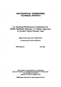
Abstraction Of Representation Figure 1. Technology Topology and representative technology components.
A Tool For Understanding In early 1995, we started looking at how diverse Object-Oriented concepts worked together to assist in the development of large-scale systems. In particular, we wanted to know how we could use our knowledge in areas of domain modeling, architectural styles, frameworks, kits, and object-design patterns to ease and stream-line the development of a system. The result of this effort we termed an Object Topology in the sense that it provided a road map of how these technologies worked together. Our result was documented in a previous paper [Tepfenhart]. Since that time, we have extended our investigations to include other development paradigms including conventional procedural programming, relational databases, artificial intelligence, and web technology. In the course of our investigations it became very clear that we were dealing with very diverse technologies, each of which has its own vocabulary and supports software development in very different ways. It turned out that each technology has its’ own topology - a different road map for getting from requirements to working system. Technology Topology This section of this paper introduces the concept of a technology topology. A topology is a description of the properties of a surface. A road map is one example of a topology. Road maps use longitudes and latitudes as the basis for organizing the points on the map. Longitude and latitude are the coordinates for the topology. A technology topology is a road map for using a software programming technology. In a technology topology, we use the abstraction of the representation and the application domain dependency as the two coordinates by which we organize points on the map. Elements of a technology that use pictures and/or natural language are said to have a very abstract representation. Elements in which the representation can actually be executed are said to be very concrete. Machine code is very concrete, source code is moderately concrete, a design diagram is moderately abstract, and a requirements specification is very abstract. An element of a technology that is expressed in terms that have little to do with the application domain is said to be application domain independent. Conversely, an element of a technology that is expressed entirely in terms of the application domain is said to be application domain dependent. We can create a matrix of different elements of programming in terms of their general location in a technology topology. In the paragraphs that follow we will explore where the different elements lie on the
2
generalized topology. Figure 1 shows the completed topology and representative technology components in terms of their approximate placement on the topology. However, different technologies have elements that lie in slightly different points on the topology. This will be shown in the next major section. A system specification is highly application domain dependent and very abstract. This is because a system specification is typically expressed in natural language and deals with application domain concepts. The system specification for a billing system is necessarily expressed in terms of words associated with billing concepts. A good system specification is essentially technology independent -- one is interested in what the system will do, not if it is implemented using O-O or relational approaches. In practice, system specifications are often expressed in technological terms. A domain model is highly abstract and very domain dependent. It is highly abstract because graphical representations are often employed. It is moderately domain dependent because the design presents a structure that captures application domain concepts. In most technologies, the domain model forms the basis of a design. Such a design for a billing system would have components named print_bill where bill is a domain dependent term. An architecture is highly abstract and moderately application domain independent. The components of an architecture are elements which fit specific architectural styles. The representation is abstract since architectures are usually captured in a diagram. Architectures and architectural styles are application domain independent because they deal with things like platforms, files, processes, and protocols. None of these are described in terms of application domain elements. An implementation of an architectural component is a framework. These elements are typically COTS systems. A framework is moderately to highly concrete and highly application domain independent. For example, a client-server architecture which has PowerBuilder and Sybase components is highly concrete and very domain independent. PowerBuilder and Sybase have no concepts built into them of any particular domain. The power of such COTS architectural components is that they are application domain independent while providing a large degree of functionality. Application concepts have to be added as an additional step in development. The parts of a program added onto the basic implementation of an architectural component are moderately concrete and very application domain dependent. Application domain concepts identified in a domain model are captured in a programming language. Programming languages are moderately concrete forms of representation (an executable version is easily achieved by compiling and linking). In a programming language, concepts are captured in the form of variable names (PO_Number) and operations (compute_total_bill). An executable program is highly concrete and very application domain dependent. That is , an executable program runs and thereby provides the functionality described in the a system specification. Executable programs are necessarily technology independent. That is, we can’t tell by it’s executable code if it was implemented using O-O, relational, or AI technologies. There is a final technology component that has only recently become recognized. This component captures the ‘Tricks Of The Trade’. These are the programming heuristics, rules, and patterns that describe how to recapture one technology component into the representation of a second technology component. Programming practices are generally neutral in application domain specificity and neutral in abstraction. On one hand, they describe patterns of domain terms. On the other, the patterns are usually in terms of very abstract domain terms. They relate highly abstract representations with rather concrete implementations of the information. Development Geodesic If we examine a technology topology, one sees that there are islands of technology components that are reflected across the line of neutral abstraction. A system specification is reflected by an executable program. A domain model is reflected by an implementation of the application domain component. An architecture is
3
Application Development Path
Technology Independent
Framework Development Path
Dependency On Application Domain
Library Development Path
Dependent Concrete
Abstract
Abstraction Of Representation Figure 2. Development Geodesics. reflected by a framework. The mapping of an abstract representation to a concrete representation is a development activity. A development geodesic can be viewed as the path of least resistance in the development of a product from a point on the abstract side of the graph to its counterpart on the other side of the topology. Three such geodesics exist on the topology that represent the reflections across the line of neutral abstraction. These are shown in Figure 2. The dashed path des cribes the development route for taking a domain model into a set of business code. The path traverses through the ‘tricks of the trade’ node - a practice which real developers perform to achieve high quality and high performance code. In the object-oriented development world, these tricks of the trade are object design patterns which tell how to map an object model into an object implementation. The dotted path describes the development route for taking an architectural style into a framework. Again, this path traverses through the ‘tricks of the trade’ node. In this case, some of the tricks of the trade are the identification of COTS products that provide a basic framework for an application. These include products like X-Windows, DBMS, Web Servers, and others. The solid path describes the development route for taking a system specification into an operational application. While not really drawn, this path takes into account the other two development paths as well. The core path travels from system specification to a domain model and then onto an architecture. This is all work performed using abstraction representations. From those points, development is being performed to map them onto frameworks, sets of business code and then integrating them into an application. The development effort required to translate the abstract representations into concrete representations for domain models and architectures will follow the paths described previously. The lines between nodes represents a kind of effort to tie all these technologies together. The traversal from system specification to a domain model is traditionally a design process. A common manifestation of the design process is a requirements traceability matrix. A top-level design is mapped onto an architecture.
Diverse Technologies There are many software technologies that have reached maturity. With maturity, we now try to exploit the strengths of each in obtaining critical business solutions. In the following sections, we examine several technologies and identify the topologies. In all cases, the axes remain the same -- abstraction of the
4
Independent
Dependency On Application Domain
Architectural Styles CORBA Decision Support Requester/Provider Object Design Patterns
Frameworks
Object Analysis Model System Specification
Kits Application
Dependent Concrete
Abstract
Abstraction Of Representation Figure 3. Object Topology. representation and dependency on the application domain. The difference among these technologies are the specifics of the locations on the topology of the components and the geodesics connecting the points. This will become obvious as we describe the topology of each technology. In particular, we will see that they differ even in terms of the words used to express basic programming concepts. Object Topology Object Oriented approaches to solving business problems have resulted in a number of very large, reliable, and functional systems. They are becoming the cornerstone of businesses as they demonstrate the ability to rapidly adjust to changing business requirements. The topology for the object-oriented paradigm is shown in Figure 3. In an object topology, a domain model is expressed in terms of an object analysis model. In this technology, domain elements are captured in the form of objects, relationships among objects, and behaviors which objects can exhibit. Class systems for objects are communicated in the form of graphic illustrations with relationships expressed as links or attributes. Behaviors are captured in the form of event-trace diagrams. Certain architectural styles are common in object systems. In particular, one deals with architectural styles such as decision support, requester/provider, and event-driven styles. These are reflected in the types of frameworks and COTS available for object systems. In particular, one has MFC from Microsoft, Zapp from Rougewave, ObjectStore from Object Design, and Orbix from Iona to name a few. One area in which there has been a lot of major research of late concerns the ‘tricks of the trade’ technology component for the object paradigm. This has lead to a clear set of specifications concerning how to map the object model into source code. These specifications are object design patterns and the use of these patterns is becoming increasingly more wide spread. Relational Topology The technologies associated with relational data bases maps into a topology of its own. Relational systems have long held a major role in business applications. The topology for the relational paradigm is shown in Figure 4. This topology should be compared with the one for the object paradigm.
5
Independent
Dependency On Application Domain
Database Engines
Architectural Styles Client-Server Pipeline
Design Patterns
Canned Queries Libraries
System Specification
Application Dependent Concrete
Conceptual Analysis Model
Abstract
Abstraction Of Representation Figure 4. Relational Topology. In a relational topology, a domain model is expressed in terms of an entity-relation model. In this technology, domain elements are captured in the form of tables, relations among tables, and operations over table entries. The entity-relation model is expressed in the form of graph illustrations that reflect a table view of the world. An entity-relation model is very different from an object model. Certain architectural styles are common among relational systems. The most widely known is the clientserver architecture in which their is a common server and any number of clients that may be presentation systems and/or decision support systems. These architectural elements are reflected in the COTS products available for relational systems. DBMSs are one kind of product available on the server side and client-side products like PowerBuilder are becoming more widely used. The ‘tricks of the trade’ technology component are being captured in the form of Design Patterns which relate how different domain models can be implemented in tables and queries over those tables. AI Topology AI is often an overlooked technology in obtaining business solutions. However, rule based systems are still quite a factor in the software enterprise. The AI topology is shown in Figure 5. In a vein appropriate to the fuzzy heuristic driven AI world, developers often talk in terms of development heuristics instead of design patterns. In an AI topology, a domain model is expressed in terms of a knowledge level analysis model. The principle concepts involved are: facts, predicates, rules, and chains of inference. These elements are usually captured in natural language form. AI systems are usually implemented as either consultation systems or embedded systems. The COTS products are limited to inference engines and development tools that support either mode of operation.
6
AI Paradigm Independent
Dependency On Application Domain
Inference Engines
Architectural Styles Embedded Consultation
Design Heuristics Domain Knowledge Rule Sets System Specification
Application Dependent Concrete
Abstract
Abstraction Of Representation Figure 5. AI Topology. Web Topology One of the hottest technologies in the market place today is web technology. This promises to solve many of the problems associated with large scale use of applications in non-homogeneous computing environments. The browser, available across many platforms, provides a front-end to an application on a back-end machine. The topology for web technology is illustrated in Figure 6. In a web topology, a domain model is often expressed in terms of pages, forms, and state models. In this technology, information is presented as a page of material, a form to be filled out, or as a single snap-shot in a sequences of pages. Expression of design is achieved using CGI bin scripts and HTML documents.
Independent
Dependency On Application Domain
Architectural Styles Client-Server Hypertext
Servers Browsers
HTML & CGI Forms & State Models
CGI_BIN
System Specification
Application Dependent Concrete
Abstract
Abstraction Of Representation
Figure 6. Web Topology.
7
In terms of architecture there are client-server systems and hypertext documents. COTS products include the servers, the clients, and some authoring tools. There are some COTS systems that provide a page generation between the web server and permanent data stores (such as DMBSs). The development geodesic is currently poorly understood since individuals are still exploring the topology and the topology is still undergoing tremendous changes. One of the most common appears to layout the basic page appearance and to implement whatever processing needs to be performed as a single cgi-bin program on a page-by-page basis.
Building Hybrid Systems It is clear that as systems get larger and more complex that the strengths of any one technical approach will fail to meet business needs totally. To counter this, mixtures of technical approaches are being employed. If we were to place any two technology topologies one atop the other, we would see that each has the same components, but the components are placed in slightly different locations. As suggested in the previous section, this is because the different technologies provide different abstractions for expressing application domain concepts. The result of mixing two paradigms and trying to treat them as a single technology is illustrated in Figure 7. A key to understanding the problems associated with mixing technologies to recognize is that two points now reside in each area where a single point used to exist. There are now two different kinds of domain models, one which is appropriate for one technology and another for the other technology. There are two points for architectural styles, each point identifying a set of architectural styles appropriate for the individual technologies. There are two points in the frameworks region denoting that there are different architectural styles being implemented for the two different technologies (and the fact that there are different COTS products). Finally, there are two sets of business code reflecting the fact that two different domain models are being captured. The significance of this picture becomes most apparent as a result of tracing the development geodesics on the topology. The development paths become much more complicated since we have the existing paths for each technology and additional segments that have to be added to connect the dual points. It is necessary for the connections between dual points to be made so that one ends up with a fully functional application. In particular, if the two sets of business code do not integrate seamlessly, then the application won’t function. In order for the two sets of business code to integrate seamlessly, then some sort of integration models must exists for the two domain models. If one takes the superficial view that each segment of a development geodesic represents some standard unit of work that must be performed during development, it is obvious that more work is required to implement an application. In fact, one could easily be convinced that mixing technologies can require almost three times as much work as implementing from scratch within a single technology. The necessary work could be computed as the sum of the work required for one technology plus the work for the second technology plus the work for integrating them.
8
Independent
Dependency On Application Domain
Architectural Styles COTS
Tricks Of The Trade
Business Code
System Specification
Application Dependent Concrete
Domain Models
Abstract
Abstraction Of Representation
Figure 7. Mixing Two Different Paradigms. Of course, considering each link to represent some standard unit of work is a superficial view. This view ignores some of the advantages which one has when COTS products are employed in a system. However, the introduction of a COTS product does not eliminate the work entirely. Hence each link does represent some amount of effort, but that amount will differ according to technology and COTS products supporting it. That is why using a COTS product in an application can be cost effective. There is another observation that can be made on the basis of Figure 7. This observation is that while the individual paths for each technology can be well known and understood, the little development links necessary to connect the development nodes can be virtually unknown. This is shown by the fact that there aren’t any ‘tricks of the trade’ for linking two technologies. In essence, one aspect of using two technologies is identifying how the domain models can be linked together, what architectural styles work well together, how to connect frameworks, and how the business code can be integrated across technological abstractions. This kind of unique, first of a kind activity is one that can require time and money. Further more, it carries with it a high degree of risk. The trade-off concerning the relative costs of staying within a single technology or mixing technologies has to be made on a total cost perspective. Staying within a single technology might lead to high costs because of the effort associated with developing of a major functionality which is not provided in any other way. On the other hand, the cost of mixing two technologies may be high because of the effort of development for each technology and the difficulties in connecting them together.
Summary This paper has presented a tool, the technology topology, for understanding COTS integration challenges. It used this tool to describe the relative relationships among the components of a technology. It described how development of an application traverses a geodesic across the topology. A major section of the paper dealt with the different kinds of software technologies. It identified the basic concepts and laid them out on the topology. This was done as a preparation for demonstrating how two different technologies fail to overlap on the topology. The naturally arising differences in location on the topology was identified as the major source of integration challenges. It showed how development of a system using two separate technologies could easily require much more work than development from scratch using a single technology.
9
We did not cover some issues associated with COTS integration. These issues include a lack of maturity of a technology. An example of this is the Web Technology which is still in its’ infancy and one in which not all of the major technological components have been adequately developed. Another issue deals a lack of maturity in a product. Not all products are equally mature within a technology. This lack of product maturity can demonstrate itself as a lack of basic features or inconsistant application of a technology. Also, an immature product can be very buggy. Each of these issues raise additional integration challenges as developers try to work around bugs in one product by implementing a feature in another.
References [Tepfenhart] 1997.
Tepfenhart, W.M, and J. Cusick, “A Unified Object Topology,” IEEE Software, January,
10


![[hal-00346774, v1] IS-COTS: a help to COTS Products](https://m.moam.info/img/260x300/hal-00346774-v1-is-cots-a-help-to-cots-products_5c2fe422097c478b788b46d1.jpg)