alone is already useable for making simple selections, similar to making a (random) .... The illustration in Figure 6a shows the six sides, numbered with die-like ...
Using an Autonomous Cube for Basic Navigation and Input Kristof Van Laerhoven, Nicolas Villar, Albrecht Schmidt, Gerd Kortuem, and Hans Gellersen Department of Computing Lancaster University LA1 4YR Lancaster
{kristof, villar, albrecht, kortuem, hwg}@comp.lancs.ac.uk
ABSTRACT This paper presents a low-cost and practical approach to achieve basic input using a tactile cube-shaped object, augmented with a set of sensors, processor, batteries and wireless communication. The algorithm we propose combines a finite state machine model incorporating prior knowledge about the symmetrical structure of the cube, with maximum likelihood estimation using multivariate Gaussians. The claim that the presented solution is cheap, fast and requires few resources, is demonstrated by implementation in a small-sized, microcontroller-driven hardware configuration with inexpensive sensors. We conclude with a few prototyped applications that aim at characterizing how the familiar and elementary shape of the cube allows it to be used as an interaction device.
Categories and Subject Descriptors H.5.2 [Information Interfaces and Presentation]: Interfaces – Haptic I/O, Input devices and strategies.
Other crucial constraints are battery power, as batteries need to be replaced or recharged periodically, and robustness and reliability, since people might treat these objects forcefully. The focus of this paper is not so much on ‘digitizing’ an existing object; it concentrates more on the creation of a novel object having the shape and form factor of an elementary threedimensional structure: a cube or die. Certain properties, like its symmetry and well-known shape, make it relatively easy to model, both in software and in the mind of the user. Using sensors that track a notion of its state, this cube can be used as a basic input device for selection and navigation, while blending in with the environment and remaining easy to physically and mentally grasp. Further assumptions are the cube’s physically separation from any appliance (a cable might encumber interaction), and that it broadcasts its state as a service to the environment, rather than one specific appliance.
User
General Terms Algorithms, Reliability, Human Factors, Verification.
Keywords Sensor-based tactile interfaces, haptic interfaces, Markov chain, Maximum Likelihood estimation, Gaussian modeling.
1. INTRODUCTION One of the goals that researchers in ubiquitous computing strive towards is the integration of computing technology into objects that are different from traditional functional appliances: the objects need to mix more fluently in everyday environments, and interaction should be intuitive. Making these objects look, feel, and behave familiarly for the sake of the user often results in very tight constraints for the designers of its hardware and software. The affordance and familiarity of an object are major factors for interaction with it. Apart from its shape and feel, size is important as well: The additional electronic components should be contained within the augmented object, without enlarging it. Permission to make digital or hard copies of all or part of this work for personal or classroom use is granted without fee provided that copies are not made or distributed for profit or commercial advantage and that copies bear this notice and the full citation on the first page. To copy otherwise, or republish, to post on servers or to redistribute to lists, requires prior specific permission and/or a fee. ICMI’03, November 5–7, 2003, Vancouver, British Columbia, Canada. Copyright 2003 ACM 1-58113-621-8/03/0011…$5.00.
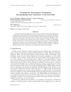
Figure 1. Picture of our transparent version of the cube, with all of its electronic components fixed inside. We present an augmented cube the size of a large die, which wirelessly transmits which of its sides is up, its orientation, and whether it went through a predefined gesture. This paper will concentrate on key choices in the design of the algorithms, since they allow the cube to have low cost, small form factor, and fast response time: •
The cube’s orientation is inferred, using the data from accelerometers only, rather than utilizing (bigger) gyroscopes or similar sensors.
•
The software runs on a standard PIC microcontroller that has limited memory. It is well suited for embedded devices.
The cube is intended to be used by applications in its surroundings. The applications pick up its transmissions and translate them into actions for selection and navigation tasks.
2. HARDWARE During the prototyping phase, the choice of hardware is important, since it has direct consequences for the remainder of the system design. The cube as an object has to remain small and robust enough for the users to handle it, and its “digital self” needs to be accurate and autonomous so it can work properly for long periods without requiring cabling for power and communication.
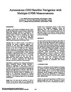
2.1 Basic Processing: PIC Microcontroller The heart of the hardware is a Microchip PIC microprocessor (PIC18F252), which is small, fast (10 Mips), consumes little energy (25 µA / 0.2 µA standby), and is easy to interface to the sensors and communication module. The downside is that the entire software for processing the sensor data and broadcasting it via a wireless protocol has to fit in a tiny program memory (32Kbyte) and only has access to a small amount of data memory (1536 bytes). PIC Microcontroller
BIM2 RF transceiver
ADXL311 accelerometer QT110 proximity
Both types of sensors are particularly cheap in power consumption (400µA / 20µA), and price (5 USD / 1.6 USD1) per accelerometer and proximity sensor respectively, due to their manufacturing process and presence in a large number of applications. Other sensors that would track the cube’s movements are significantly larger and more expensive. Gyroscopes, for instance, are being used in similar hardware to get an additional three degrees of freedom (by explicitly sensing rotation around the three axes). They are known to drift, however, and it is common for them to also include a temperature sensor and voltage reference to condition the signal. The manufacturing process is more complicated, and therefore drives up the package size and price (typically around 40 USD1 [2]); gyroscopes also require a significant amount of current (typically 6 mA [2]). In this paper, the sensing is limited to inexpensive and small inertial acceleration sensing, with an additional algorithm included on the microcontroller to compensate for the lack of explicit rotation sensors.
2.3 Communications The communications module is a Radiometrix BIM2 chip that transmits and receives data wirelessly (via FM) over an approximate range up to fifty meters indoors. Its relatively low power consumption for an RF module (~8 mA) and considerable data rate (64 kbps) make it an ideal interface between the cube and surrounding applications. Unlike many tracking appliances, the cube will only output information about itself to its environment when its state has changed or when a certain gesture is performed, thus preserving the batteries as much as possible. Wireless transmission is by far the most power-hungry component of the cube.
2.4 Characteristics Figure 2. The two stacked hardware boards with the major components annotated. A battery (coin-sized or 2 AAA) and second accelerometer are not visible from this angle.
2.2 Sensors The microcontroller we used has fourteen inputs for binary sensors and a built-in analog-to-digital conversion unit that allows five analog sensors to be attached. Our objective, however, to keep the hardware as simple and low-cost as possible without giving in too much on performance, means that we kept the number of sensors low: •
•
Two dual-axis accelerometers (ADXL311) measure both dynamic acceleration (e.g., vibration) and static acceleration (e.g., gravity) in a plane. The sensors’ ability to measure gravity gives us the opportunity to discriminate in contexts where acceleration may be zero (such as different positions of the cube). We used two accelerometers to get acceleration in three dimensions (X-Y and X-Z). One capacitive sensor (QT110) measures proximity of the user’s hand (i.e., whether the user is holding the cube or not), mainly to wake up the microcontroller from standby.
The prototype hardware used in this paper consists of two boards (as shown in Figure 2) that stack on top of each other: One board makes up the core section, containing the microcontroller, communications module, and a coin-size Lithium cell on the bottom. The second board has the acceleration and proximity sensors, plus a few empty slots for future sensors, should they be required. The total setup for one cube, including the printed circuit board and all components, costs about 50 USD. The entire system runs on a three volt Lithium coin-cell battery, or two AAA batteries which give a lifetime of approximately four months with the current embedded software and normal usage (“normal” usage defined by the first application in section 7).
3. MODEL OVERVIEW Our objective is to give the cube a digital representation, so that it can offer its state as a service to applications in its environment. What states it can and should detect, and what behaviors can be detected, are vital considerations for obtaining a model for the cube. The system that we implemented has three modules: the first estimates which is the top side of the cube, the second uses this 1
Prices per unit for 100+ purchased, on 28/04/2003.
information with prior states to estimate the direction to which all other sides are pointing, and finally the third model overrules the others if it is confident enough that a gesture was performed. Figure 3 gives an overview of the system with some examples. What is direction of all sides?
4. FINDING THE TOP SIDE
Figure 3. The three modules that produce the cube’s output, abstracting from the raw acceleration data.
3.1 Which Side Is Up? A first approximation of a model estimates which side of the cube is ‘on top’, which we will define as relative to the user but assume to be similar to pointing upwards if the cube would be lying on the ground. Note that this is just a rough approximation of the cube’s state, especially as it doesn’t include rotation in the X-Y plane parallel to the top side; we know the orientation of the top and bottom sides, due to the symmetry of the cube, but not the orientation of the four other sides. However, this basic model alone is already useable for making simple selections, similar to making a (random) selection by rolling a die. Accelerometers that operate in three perpendicular dimensions are a well-known tool to estimate the position of an object, relative to the earth’s gravitational field. We will model the top side by analyzing the accelerometers’ sensor data for each possible side, and using these six models for estimation of the side that is most likely ‘on top’.
3.2 Orientation Of All Sides Relative To User Instead of just expressing the top and bottom sides, a more appropriate model would be to represent where each side is pointing to, relative to the user. These orientations do not need to be precise measurements in degrees: a more useful set would be the already existing ‘on top’/’Up’ and ‘on bottom’/’Down’, accompanied by the other directions (defined as ‘North’, ‘South’, ‘West’, and ‘East’) again relative to the user. Rather than throwing away the previous model and adding some sensors that sense orientation in all three dimensions, we use the previous model to estimate the orientation of all sides. This method will require an a priori known starting orientation, or at least the orientation of two perpendicular sides.
3.3 Gestures A third addition to the cube’s model, still using the minimal set of sensors from the hardware discussed in section 2, is a distinct set of gestures that the user can perform with the cube in hand. The
The three-dimensional arrangement of the accelerometers allows a very easy and robust way to work out which side of the cube is on top. We can assume that there is no drift in the sensor signals, and only a small amount of noise. Furthermore, as there are four signals available (two per accelerometer), all four will be used to distinguish the six possible sides facing upwards. Arguably, the fourth (redundant) acceleration signal will only give a small information gain, but is included nonetheless as it will not perceptibly affect the real-time performance of the software on the microcontroller.
4.1 Multivariate Gaussian Modeling of Sides Due to the properties of the acceleration sensors, one can expect that the combined signals they produce will indeed vary for each orientation of the cube. An obvious method to model the data from each side being the one on top is to represent it as a fourdimensional Gaussian:
Gi (x ) =
1 ( 2π ) 2
Σi
e
−
1 ( x − µ i )T Σ i −1 ( x − µ i ) 2
where i ranges from 1 to 6 to identify the sides of the cube, x specifies a four-dimensional vector with the sensor readings, and the two parameters µ and Σ indicate the mean (average) vector and covariance matrix, respectively. The Gaussian for each side being the one on top can thus be characterized by obtaining the averages and the covariances from sample data. This can be done by recording a dataset for each side facing upwards, and storing the averages and covariances from these datasets as pre-calculated values in the hardware. It is however also possible, and feasible, to code the calculation of the averages and covariances into a routine that can reassess or recalibrate these parameters at run-time. Sample data from the cube being placed on all six sides successively is plotted as a time series in Figure 4.
1
2
3
4
5
6
Sensorvalues
Has a gesture been performed? Output
Acceleration sensors
Which side is ‘on top’?
module that will recognize the gestures runs parallel to the other modules, overriding it whenever the most likely gesture is recognized with a sufficient probability. As the given sensor’s capabilities are limited, gestures will typically involve signals with a high variance and a distinct pattern.
Time (±10 milliseconds)
Figure 4. Samples from the cube’s sensors, while placed on all six sides successively (labeled in the plot). To visualize the Gaussian models, a dimensionality reduction algorithm (FastICA [14], based on Independent Component Analysis [3]) was utilized to map the four-dimensional data space
(which is hard to visualize) into a two-dimensional space. Figure 5 shows the six two-dimensional Gaussians (notice how they are evenly distributed over the input space) with a sample trace of a cube being rotated around, cycling through all six states.
Finally, eliminating the constants and reversing the sign produces an easier formula that gives the most likely top side of the cube:
(
−1
arg min ( x − µ i ) T Σ i ( x − µ i ) + ln Σ i i
)
By filling in the four acceleration values x=(x1, x2, x3, x4) into this formula, and having computed the µi , ln|Σ|, and Σ-1 beforehand, one gets the side i that is most likely the top side. This calculation fits easily into the microcontroller’s program memory and does not need an excessive amount of stored data: In the C source code for the microcontroller, the computation per input, per side, requires 20 multiplications, 4 subtractions, and 16 additions. The amount of time that this takes is negligible, compared to the other code segments for reading the sensor values and establishing communication.
4.3 Re-estimating Parameters at Run-time Figure 5. Mapping to a two-dimensional space to visualize the Gaussians for all six sides. The line trace is a trace plot of the readings while the cube was turned around from side to side.
4.2 Maximum Likelihood Estimation The Gaussians will be used for each sample reported by the acceleration sensors to establish which side these readings belong to. Using the formula in the previous section, the side i for which the Gaussian Gi(x) has the highest value for the current sensor readings x, will be the most likely side that is on top of the cube. To fit this into a Maximum Likelihood (ML, see [11] for a brief introduction) estimation procedure, we start with Bayes’ rule:
P (T = i x ) =
P( x T = i ) P(T = i ) P( x )
where P( T=i | x ) is the posterior probability that the side i is on top, given the sensor data x, and P( x | T=i ) is the prior probability that sensor data x enters the system, while it is given that side i is on top. The two other values, P(T=i) and P(x), signify the probability that the cube has i as a top side and the probability that the sensors read the vector x, respectively. Since only the side i that is the top side is of interest, we search for the maximum argument instead of just the probabilities:
P( x T = i ) P(T = i) = arg max(Gi ( x ) ) arg max P( x ) i i by replacing the prior probabilities with the Gaussians, and assuming that all sides of the cube are equally likely to be on top, P(T=i) = 1/6.
Not only does the estimation procedure fit easily on a microcontroller, the generation of the covariance matrices and means was implemented on the microcontroller as well. This could be used for re-calibration (although the sensors do not drift as such, sides may need to be re-mapped or the hardware might be repositioned within the cube), or during an initial ‘training phase’. The one restriction that affects the accuracy is the size of the datasets per side, due to the limited amount of available memory.
5. MODELING THE CUBE 5.1 Symmetrical Properties Of The Cube The cube is known in mathematics as a hexahedron, from the group of polyhedrons, or more precisely isohedrons, consisting of six square sides, 8 vertices, 12 edges, and having numerous interesting properties (see [15] and [16] for an introduction). In the case of a die, the cube has opposite faces, which are labeled by number to always sum to seven. This gives two possible mirror image arrangements in which the numbers 1, 2, and 3 may be arranged in a clockwise or counterclockwise order about a corner. The illustration in Figure 6a shows the six sides, numbered with die-like counterclockwise arrangements, when viewed from along the three-fold rotation axis towards the center of the die. a) 2
b)
1 3
5
4
6
This can be simplified by including the natural log function to eliminate the exponential function in the Gaussian:
Figure 6. a) The arrangement of the cube in this paper follows that of a counterclockwise die. b) A 90 degree rotation along any axis through the center points of opposite faces leaves the cube invariant.
1 1 1 −1 arg max − ( x − µ i ) T Σ i ( x − µ i ) − ln(2π ) − ln Σ i 2 2 2 i
The most important symmetry of the die for this paper is that it remains invariant when applying certain sequences of rotational transformations of 90 degrees along the axis through the centers
of opposing faces. Figure 6b shows these three axes. We will consider for the remainder of this paper that the cube has, like the die in Figure 6a, numbered faces, but do not assume that they are visibly marked on the object.
Given this set of transitions, and denoting a state by X,Y where X is the top side and Y is the south side, a finite state machine can be built (See state transition diagram in Figure 8). Notice that all 24 possible states can be reached with the four transitions defined above.
5.2 Defining A Basic Set Of States A certain state of a cube will be defined as an arrangement of sides according to the following directions from the view of the person holding it (see Figure 7a for an illustration): • • • • • •
Top / Up: the side that faces upward Bottom / Down: the side that faces downward West: the side that faces to the left East: the side that faces to the right North: the side that faces away from the user South: the side that faces toward the user
With these definitions in place, two important remarks can be made about the notation of a state: First, in general, for a person holding the cube without knowing or observing any labels of the sides, there are twenty-four possible states. Second, by exploiting the cube’s structural properties and labeling each face of the cube as mentioned in the previous section, a given cube’s state can be described by knowing only the direction of two adjacent faces. It is therefore sufficient to take two fixed directions (Top and South, for instance), rather than describing a state by all six directions. a)
b)
1,2
Using the states defined in the previous section, one can define six possible 90 degree rotations between those states (two per axis, for positive or negative rotation). For reasons that will be specified later in this section, this set of possible transitions will be limited in our model to four of those (See Figure 7b): • Forward: rotating the cube so that the Top side becomes the North side • Back: rotating the cube so that the Top side becomes the South side • Left: rotating the cube so that the Top side becomes the West side • Right: rotating the cube so that the Top side becomes the East side
5,4
6,5
6,4
4,5
1,5
2,4
3,6
3,1 1,5
3,5
6,5
6,2
3,2
1,2
3,1
3,6
1,3
2,3
6,3
5,3
4,6
4,1
3,2
1,2
4,2
1,4
4,5
1,5
3,5
1,3
3,1
5,1
4,1
2,1
6,4
6,3 3,5
6,5
4,5
4,2
6,2
3,2
6,3
6,4
1,3
5.3 Modeling The Transitions
6,2 4,1
1,4
3,6
Figure 7. a) A diagram of the six parameters for defining the cube’s state from the user’s view. b) The defined set of four possible transitions. The labels for the sides in both views are relative to the user’s perspective.
4,2
4,6
2,6
4,6
5,6
1,4
Figure 8. All possible state transitions in two interlinked graphs: Links between a state (rectangles) to the left, right, up, and down another state indicate a transition after rotating the cube to the left, right, forward, and backward respectively. A cube’s state X,Y is characterized by the Top side X, and the South side Y. The smaller states specify links between the two graphs. Open links should be linked to the state on the other side of the graph: a left transition from 3,1 (in the upper-left of the second graph) links to 2,1 for example (upper-right of the same graph). The reason for restricting the set of transitions to the four mentioned above becomes clear when investigating the state transition diagram in Figure 8 in detail: One can take any state in the graph as an example, and examine all the possible transitions (up, down, left and right). All first components of the states are different, regardless which one was taken. Knowing the starting state and the first component of the destination state therefore identifies the transition, with the first component being the top side. the conclusion is consequently: For any given state, both the previous transition and the current state can be inferred by just knowing the previous state and the current Top side.
The consequences are significant: by knowing the starting state, the model can keep track of its states by just estimating the top side of the cube. The algorithm in section 4 does just that, so by combining it with the finite state machine from this section, the state of the cube and the last transition can be tracked at any given point in time. This finally means that the cube can be used for basic navigation, using the four transitions Left, Right, Forward, and Back.
6. GESTURES The model that was characterized in the previous two sections allows basic interaction by changing the state of the cube. The same sensors that measure its orientation, however, can also measure dynamic acceleration. A basic set of gestures (shaking the cube, twisting it, and knocking on it) that give distinct signal patterns is used as additional means of input. Figure 9 shows example timeseries plots for these discrete events. An important requirement for the gestures is that they must be independent of the orientation of the cube itself, i.e. the gestures must be recognized regardless of the cube’s states. The other restrictions that applied in previous sections due to the microcontroller-based platform, such as limited memory, power, and processing resources, are valid for the gesture recognition algorithms as well. Ideally, the gestures should be straightforward and familiar enough to a person that is handed the cube for the first time and asked to perform gestures like shaking, twisting or knocking on the cube. The patterns of these three gestures have certain characteristics that are distinguishable enough from one another, and from a nongesture (i.e. normal use of the cube without performing an actual gesture). The examples in Figure 9 show a high variation across the signals whenever a gesture is carried out, which validates the use of variance or standard deviation as a feature. A main difference between the shaking gesture and the twisting gesture is the number of sensors that give a strong variation, as shaking tends to be more unidirectional. The variance over a short time span is also key to distinguishing the knocking on the cube. By calculating the variances for all sensor channels over a sliding window of 50 samples, and averaging them to get an orientationindependent value, a sufficient feature is generated to make the distinction. As the averaged variance is the sole influential descriptive feature that distinguishes the three gestures, a simple
600
Sensorvalues
This section modeled the cube with a finite state machine, with states being a description of the orientation of all sides and with rotations as the transitions between the states. Limiting the transitions to left, right, forward and back rotations, gives not only a lighter model, in which all twenty-four possible states can still be reached, but also requires the knowledge of just the previous state and the current top side.
700
500 400 300 200 100
0
10
20
30
40
50 Time (+/- 10ms)
60
70
80
90
100
650 600
Sensorvalues
5.4 Summary
Euclidean minimum-distance classifier determines which gesture is the most likely one. Again, this algorithm is small and fast enough to operate within the microcontroller’s limited resources.
550 500 450 400 350
0
10
20
30 40 Time (+/-10ms)
50
60
70
900 800 700 Sensorvalues
If the previous top side was for example side 5, and the previous South side was 4, with the current Top side being side 1, then the graphs in Figure 8 can be used as a lookup table where only one occurrence can be found: state 5,4 linked to state 1,4 via the Left transition.
600 500 400 300 200
10
20
30
40
50 60 Time (+/- 10ms)
70
80
90
100
Figure 9. Time series plots (from top to bottom) for the gestures “shaking”, “twisting”, and “knocking”. The horizontal axes mark the time, the vertical axes show the sensor signals for the four accelerometers. One of the short-term future work goals in this research is to implement a re-training procedure similar to the one for finding the top side. This would complete the cube’s autonomy, and make it fully re-configurable at run-time.
7. APPLICATION EXAMPLES The cube system discussed so far, broadcasts a message over a wireless link whenever it detects that it is being manipulated. This can be triggered by either placing the cube on a different side (changing its state), or performing one of the cube’s predefined gestures. The cube’s output, when picked up by a receiver, has the following format: “[C ]” with each of the variables (in italics) represented by a number, followed by a value that indicates confidence in the prediction (mainly for debugging purposes). Two implementations are discussed in this section to illustrate how this information could be utilized by an application for which the cube can be used as an input device.
7.1 Controlling Audio Mixer Profiles The Innovative Interactions Lab at Lancaster University is a ‘living lab’ meeting area which is fitted with several large-screen displays, sensors, and a high-end 8-channel audio system. The
audio system is controlled through a mixer that is hooked up to a number of devices, such as a TV, a net-meeting environment, MiniDisc player, CD player and several input sockets positioned around the lab space. Utilizing the audio system for any of these appliances means going to the mixing panel, switching the appropriate channels and setting the sliders to the required volume on the mixer. In practice, this requires expertise with not only the mixer settings, but also the entire audio system.
Figure 11 shows a demonstration program that asks the user to navigate an animated dot on the screen to a certain position and perform a certain action. Navigation is achieved by rotating the cube 90 degrees in the desired direction, while actions are represented by the gestures “shaking”, “twisting”, and “knocking”.
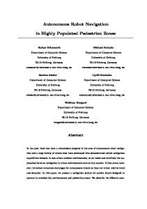
By using the cube as a simple, tangible interface, anybody in the lab can set the audio system to one of the six most popular settings by placing the cube so that the side that relates to the desired appliance faces upwards. The cube’s output is sent to a base station that converts the packets to a MIDI stream that controls the mixing panel (see Figure 10 for a picture of the lab setup), as well as two large plasma screens.
Figure 11. The cube is used in a demonstration game to navigate a dot on the screen by rotating the cube 90 degrees forward, backward, to the left or to the right. Actions like shaking the cube and knocking on it execute specific tasks. Notice that the cube has no labeled sides.
Figure 10. The cube that selects audio profiles for the lab’s mixer panel has labeled sides corresponding to the available audio sources. The side on top (TV in this case) is selected. The small circuit board above the camera to the right of the plasma screen is the base station. The inset shows the equipment that drives the lab’s audio system; sliders and channels are automatically set to one of six common profiles by the cube. This first example uses merely the first module of the cube (“which side is up?”), but it has been deployed for half a year and has become an accepted part of the lab, being used by a number of people on a daily basis.
7.2 On-Screen Navigation Another example uses the outputs of the cube’s second and third algorithm modules as well, which provide applications with the direction of all sides, the last state-transition (forward, back, left or right) and gestures.
Rotation of the cube along the Z-axis during the game results in the model being distorted, as mentioned in section 5. Early tests, however, show that users are able to quickly correct this situation and rotate the cube back in the right position. Another restriction for the application is that the cube needs to start with a known starting state, which requires resetting it while holding the cube with a marked side towards the user. Envisioned applications range from simple user interfaces for children and disabled users, to games where four-way navigation and few actions are sufficient as interaction primitives (e.g. early text-based adventure games, or board games).
8. RELATED WORK Many input devices exist that have embedded motion sensors, usually a combination of accelerometers and gyroscopes (see for instance [1] or [3]). Most of them are considerably different from our approach as they track a relative two-dimensional or threedimensional position in space, rather than states, and transmit these data continuously to a dedicated application. Benbasat and Paradiso [4] describe a device that is similar in form and sensing hardware. Their Inertial Measurement Unit (IMU) is cube-shaped and has four acceleration sensors, but also three gyroscopes. The algorithms on the IMU are specifically geared towards gesture recognition, exploiting it as a generic sensor that is attached to another object. The framework around the IMU provides ‘atomic gestures’ to an application’s designer that can be combined with AND and OR operators. The IMU cube is not
envisioned as a standalone device, and therefore does not have, nor require, the internal state model that allows the basic navigation described in this paper. The fundamental shape of the cube has inspired others to create tangible interaction elements that are cube shaped, but require additional external tracking equipment (such as reference beacons or tablet surfaces). Olwal [12] envisions cubes as core components in an AR interface, Frohlich and Plate track position and orientation in three dimensional space of their Cubic Mouse [7], a cube with three orthogonal rods through the sides and buttons, and Sharlin et al. use a collection of cubes to assess 3D constructive abilities in the Cognitive Cubes project [14]. The Toolstone [13] is a brick-like object on a tablet that senses manipulation of itself by using internal coils. The Triangles system [8] uses a basic two-dimensional triangle to create a system for interaction with digital information. Brick-like objects have been used for control in computer vision [6].
11. REFERENCES [1] 3D Mouse from Handview: http://www.handview.com/ [2] ADXRS150 gyroscope: ±150°/s Single Chip Yaw Rate Gyro with Signal Conditioning Data Sheet (Rev. A, 1/03)
[3] Bartlett, J.F. Rock ’n’ scroll is here to stay. IEEE Computer Graphics and Applications, Vol. 20-3, May/June 2000. pp. 40–45.
[4] Benbasat, A.Y. and Paradiso, J. A. An Inertial Measurement Framework for Gesture Recognition and Applications. In Ipke Wachsmuth, Timo Sowa (Eds.), Gesture and Sign Language in Human-Computer Interaction, International Gesture Workshop, GW 2001, London, UK, 2001 Proceedings, Springer-Verlag Berlin, 2002.
[5] FastICA Toolkit, Helsinki University of Technology. http://www.cis.hut.fi/projects/ica/fastica/ [6] Fjeld, M., Voorhorst, F., Bichsel, M., & Krueger, H.
9. CONCLUSIONS A tangible cube that embodies basic gesture recognition with directional state and navigation information was introduced. In hardware, simple acceleration sensors are employed, leading to an efficient design in terms of energy consumption and size constraints. In software, the lack of additional sensors is compensated by an internal model of the cube’s symmetrical properties in a state diagram, a rigid maximum likelihood estimation procedure to guess the states, and crude gesture recognition. The algorithms fit comfortably in a microcontroller environment without needing further calculation outside the cube; wireless communication is only activated when either a gesture is performed or the cube’s state has been changed. Initial experiments in which the cube is deployed in real-world contexts suggest that the cube is reliable and its batteries have an adequate lifespan. Further experimentation is scheduled to investigate the usability of the cube, the effects of its design (such as material, color, weight, or edges), and its limitations and fortes as an input device. More in-depth hardware and algorithm descriptions, plus the Matlab scripts and datasets that were used to create the graphs in this paper are available at: http://ubicomp.lancs.ac.uk
Exploring brick-based camera control. In H.-J. Bullinger & J. Ziegler (eds): Proceedings of HCI International’99, (the 8th International Conference on Human-Computer Interaction), pp. 1060-1064. 1999.
[7] Froehlich, B. and Plate, J. The Cubic Mouse: A New Device for Three-Dimensional Input. Proceedings of CHI 2000, pp. 526-531. 2000.
[8] Gorbet, M., Orth, M. and Ishii, H. Triangles: Design of a Physical/Digital Construction Kit. Proceedings of Designing Interactive Systems: Processes, Practices, Methods, and Techniques (ACM DIS '97), Amsterdam, ACM, pp. 125-128.
[9] Hyvärinen, A., Karhunen, J., Oja, E. Independent Component Analysis (ICA). John Wiley & Sons, 2001.
[10] iMAR Triaxial iTGAC-FK Sensor Cube with Fiber Optical Gyros and Accelerometers. http://www.imarnavigation.de/englishside/dat_engl/tgac_fk.pdf
[11] Mitchell, T. Machine Learning. McGraw-Hill c, 1997. [12] Olwal., A. Unit—A Modular Framework for Interaction Technique Design, Development and Implementation. Master’s project at the KTH, Stockholm, Sweden, executed in the Department of Computer Science at Columbia University, New York, USA. 2002.
[13] Rekimoto, J. and Sciammarella, E. ToolStone: Effective use
10. ACKNOWLEDGMENTS The prototypes in this work have been based upon earlier hardware and studies from the Smart-Its project (funded by the EU’s IST framework), and the Equator project (funded by EPSRC, under grant GR/N15986/01 - "Technological Innovation in Physical and Digital Life"). We would like to thank our partners in those projects, as well as all our colleagues at the department who were so kind to test the cube out and give us their feedback.
of the physical manipulation vocabularies of input devices. In Proc. of UIST 2000, 2000.
[14] Sharlin, E., Itoh, Y., Watson, B., Kitamura, Y., Liu, L., Sutphen, S. Cognitive Cubes: A Tangible User Interface for Cognitive Assessment, ACM CHI 2002 Conference Proceedings, pp. 347-354, April 20-25, 2002, Minneapolis, Minnesota [15] Weisstein, E. The Cube. World of Mathematics. Online web resource. http://mathworld.wolfram.com/Cube.html [16] Wenninger, M.J. The Hexahedron (Cube). In Polyhedron Models. Cambridge, England: Cambridge University Press, p.16, 1989.