Using Artificial Neural Networks for Identification of Electrical Losses in Transformers During the Manufacturing Phase André Nunes de Souza, Ivan Nunes da Silva, Cláudia F. L. N. de Souza and Maria Goretti Zago State University of São Paulo – UNESP UNESP/FE/DEE, CP 473, CEP 17033-360 Bauru – SP, Brazil e-mail:
[email protected]
Abstract: - The paper describes a novel neural model to estimate electrical losses in transformer during the manufacturing phase. The network acts as an identifier of structural features on electrical loss process, so that output parameters can be estimated and generalized from an input parameter set. The model was trained and assessed through experimental data taking into account core losses, copper losses, resistance, current and temperature. The results obtained in the simulations have shown that the developed technique can be used as an alternative tool to make the analysis of electrical losses on distribution transformer more appropriate regarding to manufacturing process. Thus, this research has led to an improvement on the rational use of energy.
I. INTRODUCTION The rational use of energy demands a steadily following up on losses transformer during the manufacturing phase to improve the performance of the electrical system. In this sense, it is essential to identify the behaviour related to the losses in transformers. Nowadays, the companies that produce distribution transformer are concerned mainly about electrical loss because it represents not only technical but also financial damages. In this context, the electrical loss constitutes one of the most important parameters of transformer quality [1]. The real necessity of reduction of electrical loss in the power system is associated with the growing demand for reliable and flexible power supply systems to keep network operation viable in both normal and emergency conditions (overload). One critical requirement in designing transformers is to guarantee that the power dissipated in the transformer remains within an acceptable level. It is essential to comment that the total losses in a transformer have been calculated by combination of core loss and copper loss [2]. Initially, transformers are designed so that their iron losses are equal to the guaranteed ones. In practice, however, transformer iron losses have deviated from the project (theoretical) ones due to construction defects, which appear during the production phase. The reduction of transformer losses, by minimizing the effect of constructional defects, is very important task for a manufacturing industry [3]. The copper loss represents approximately 60% of the total losses of transformer. Electrical loss analysis related to the copper loss depends on the relationship among several parameters, such as temperature, resistance, current, voltage, load and copper quality. These factors have taken into
0-7803-7278-6/02/$10.00 ©2002 IEEE
account during the transformer design stage. However, it is not possible to consider all these factors to model the thermal effect in transformers due to the changing of load in the electrical system. Most of the methods used to determine transformer electrical losses are in general the ones proposed by standards organization. They both have been based on current graphs and table as well on former measurements [4]. Hence, in this way is very difficult to establish the relationship among the parameters involved in the production process that analytically expresses the electrical losses in transformers. In this sense, it is crucial to estimate and to identify losses transformer during the design phase. Considering this problem, the mapping of electrical losses in transformers through Artificial Neural Networks (ANN) can be seen as an efficient tool to provide alternatives to the conventional methodologies, generating attractive results, mainly due to the intrinsic characteristics of the technique, such as the ability to automatically learn relationships between inputs and outputs independently of the size and complexity of the problem, generalization capacity and integration facility with other computational tools. For this purpose, the present paper is organized as follows: In Section 2, it is described the basic conceptions related to the electrical losses. The Section 3 introduces some basic foundations of artificial neural networks. In Section 4, the neural approach used in the proposed methodology is shown. The Section 5 provides the simulation results obtained by the presented technique. Finally, the key issues rose in this paper and the conclusions drawn are described in Section 6. II. ELECTRICAL LOSSES Transformer’s efficiency is improved by reducing iron losses and copper losses. In order to reduce copper losses, the designer can apply one or more of the following procedures. It means, to use lower loss conductor materials, to decrease the current path length or the current density. On the other hand, the designer can reduce iron losses by using lower loss core materials, reducing core flux density or flux path length. In general, attempts to reduce copper losses cause increase of iron losses and vice versa [5]. The development of this kind of study requires remarkable knowledge in the influence of some factors, such as: copper losses, core losses, current, resistance and temperature. Some important factors are described as follow:
The determination practices of the losses for histerese it is done from:
A. Copper loss Copper loss is equal to the sum of the squares of the currents multiplied by the resistances of the various windings. As the currents are fixed by the rating, it is evidently impossible to reduce their values in order to reduce the I2R loss (Joule effect). The single factors, therefore, which may be varied by designs in order to reduce the losses to a minimum are the resistances of the various windings. The resistances should be reduced to a minimum, and to reach it is evident that the total sections of the conductors should be as large as possible, and their total lengths as small as possible. It is important to mention that an increase on the section of the conductors implies on a decrease of the values of resistance and consequently the I2R loss, there is trend of increase on the frame size, and therefore the losses in the magnetic circuit [6]. For single phase transformer the copper loss is given by:
Wj = R1I 1 + R 2 I 2
(1)
where WJ is the copper loss (Watts), R1 is the primary resistance, R2 is the secondary resistance, I1 is the primary current and I2 is the secondary current. B. Core loss Several works have been proposed in the literature for the identification of iron losses in transformer during the design phase. The approaches can be grouped into two main categories. The first group has been based on geometric analysis of the electromagnetic field of the core transformer, while the second group uses iron loss models based on experimental observations. It is defined core loss as the potency absorbed by the transformer when it is submitted to a voltage and nominal frequency, being the circuit secondary in open (without load). When a mass of metallic material is submitted to a variation of magnetic flow it is generated a force eletromotriz that results in an intense electric current, denominated of Foucault current and that causes potency losses. The losses due to the effect of this parasite current can be calculated by the expression:
PF = 2.2. f 2 .B 2 .d 2 .10 −3
PH = K S . B 1 .6 . f
where PH are the losses caused for histerese, Ks is coefficients of Steimmetz (depends on the material type used in the core), B is the maximum induction of magnetic field and f is the frequency. Thus, the core loss (P0) is constituted for sum of these two kind of losses (parasite and histerese):
P 0 = PH + PF
(4)
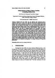
III. FOUNDATIONS OF NEURAL NETWORKS The ability of Artificial Neural Networks (ANN) in mapping functional relationships has become them an attractive approach that can be used in several types of problem [7]. This characteristic is particularly important when the relationship among the process variables is nonlinear and/or not well defined, and thus difficult to model by conventional techniques. An artificial neural network is a dynamic system that consists of highly interconnected and parallel nonlinear processing elements that shows extreme efficiency in computation. The main benefits of using ANN’s on the electrical losses processes are the following: the ability of learning and therefore generalization; the facility of implementation in hardware; the capacity of mapping complex systems without necessity of knowing the eventual mathematical models associated with them. In this paper, artificial neural networks of the type Multilayer Perceptron has been used to map the relationship among the electrical losses in transformers is related to the several variables that indicate the features to loss process. A typical feedforward ANN is depicted in Figure 1, with m inputs and p outputs, and each circle representing a single neuron. The name feedforward implies that the flow is one way and there are not feedback paths between neurons. The output of each neuron from one layer is an input to each neuron of the next layer.
(2)
where PF are losses caused for parasite current, f is the frequency, B is the maximum induction of magnetic field and d is the thickness of the core lamination.
Input Layer
x
x
When the magnetic material is submitted to an alternate field, the characteristic senoidal of the current makes the phenomenon described previously repeats in an alternate and successive way, what is denominated of magnetic histerese cycle.
0-7803-7278-6/02/$10.00 ©2002 IEEE
(3)
x
Hidden Layer 1
Hidden Layer 2
Output Layer
y
1
y
2
y
m
Fig. 1. Typical feedforward ANN
1
2
p
The initial layer where the inputs come into the ANN is called the input layer, and the last layer, i.e., where the outputs come out of the ANN, is denoted as the output layer. All other layers between them are called hidden layer. Each neuron can be modeled as shown in Figure 2, with n being the number of inputs to the neuron. Associated with each of the n inputs xi is some adjustable scalar weight, wi (i=1,2,...,n), which multiplies that input. In addition, an adjustable bias value, b, can be added to the summed-scaled inputs.
For an optimum weight configuration, E(k) is minimized with respect to the synaptic weight w, so that for each data set,
∂E (k ) ∂wlji
=0
where w is the weight connecting the neuron j of the l-layer to neuron i of the (l – 1)-layer. Finally, the weights of the network are updated using the following relationship:
x1
wlji (k + 1) = wlji (k ) − η
w1 w2
x2
u
Σ
wn
g(u)
Fig. 2. Single artificial neuron
These combined inputs are then fed into an activation function, which produces the output y of the neuron, that is: n
i =1
(5)
where g is a sigmoid function defined by: g(u)=(1+e-u)-1
(6)
The training process of the neural network consists of the successive presentation of input-output data pairs. The basic structure having one hidden layer has been shown to be powerful enough to produce an arbitrary mapping among variables. During the training, the data are propagated forward through the network, which adjusts its internal weights to minimize the function cost (weighted squared deviation between the true output and the output produced by the network) by using the back-propagation technique. The detail of the derivation of the back-propagation algorithm is well known in literature and its steps can be found in [8]. A review of the main steps of the algorithm is presented here. The function to be minimized is the sum of the average squared error (EAV) of the output vector,
E AV =
1 N
N
∑ E (k )
k =1
1 p ∑ (d j (k ) − y j (k ))2 2 j =1
0-7803-7278-6/02/$10.00 ©2002 IEEE
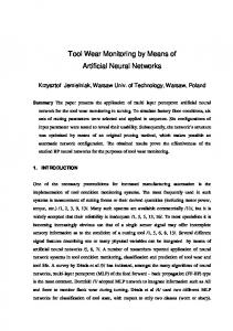
An Artificial Neural Network (ANN) of the type Multilayer Perceptrons is employed for the identification electrical losses in transformer during design phase. The variables that compose each input vector of the network are defined by those variables that indicate the losses in transformer. These variables are identified as follows: • T is the temperature (0C). • RHV is the resistance of the high voltage winding (Ω). • RLV is the resistance of the low voltage winding (Ω). • P0 is the core loss (W). • PCU is the copper loss (W). • IM is the magnetizing current (A). The output vector of the neural network has been composed by a unique variable, which represents the total loss (PT) of the transformer. The neural architecture used to estimate the (PT) of transformers is shown in Figure 3.
T
RHV
RLV
P0
PCU IM
Artificial Neural Network Multi-Layer Perceptron
PT
(7) Fig. 3. General architecture of the ANN
where N is the number of training points and E(k) is the sum of squared errors at all nodes in the output layer, i.e.,
E (k ) =
(10)
IV. THE NEURAL APPROACH
b
y = g (∑ wi xi + b)
∂E (k ) ∂w ji (k )
where η is a constant that determines the rate of learning of the back-propagation algorithm.
y
Activation Function
xn
(9)
(8)
The training network has been made by the algorithm of Levenberg-Marquardt [9], the model was trained and assessed through experimental data obtained from Industry of Transformers ZAGO.
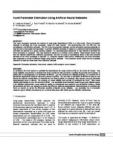
In order to evaluate the developed architecture, some preliminary tests were accomplished with the following type of transformer: • Distribution Transformer: 75 kVA • Voltage Class: 15 kVA • Type of Cooling: Oil • Tension Ratio: 13.8kV/220V The topology of artificial neural network used in this situation is described as follows: Architecture: Multilayer Perceptron Number of Hidden Layers: 1 Number of Neurons of the hidden Layer: 20 Mean Square Error: 4.99x10⁻⁴ Mean Relative Error (test pattern): 4.16x10⁻⁴ Data set training: 100
1600
1550
1500
Figure 4 shows the behaviour mean square error and the number of the training epochs. 10
1
Total Losses (Watts)
• • • • • •
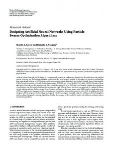
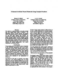
Observing Figure 5 it is possible to deduce that there is a crescent direct relationship among temperature, copper losses and total losses. The nonlinear behavior verified on Figure 5 can be lead to the inertia of the process (Joule effect). Another remarkable aspect is that using neural approach it is possible identify the ratio where the temperature influence directly to the total losses. This kind of situation would not be identified through traditional mathematical tools, proving that this process is very complex. Figure 6 shows the relationship between total losses and copper losses related to the three different values of temperature: 40 0C (superior curve), 35 0C (medium curve) and 30 0C (inferior curve).
1450
1400
1350
1300
1250
10
10
10
10
0
1200
1150 1120
-1
1140
1160
1180 1200 1220 Copper Losses (Watts)
1240
1260
1280
Fig. 6. Variation of the total losses versus copper losses considering three different values of temperature
-2
-3
-4
0
400
200
1200
1000
800 600 Training Epochs
Fig. 4. Performance of the training net
V. RESULTS AND DISCUSSIONS In this section, some preliminary simulations results and discussions are presented to illustrate the application of the neural network approach developed to identify electrical losses in distribution transformers. Figure 5 shows the behaviour of the total losses related to copper losses considering a temperature of 30 0C. 1600
Observing Figure 6 it is possible to verify the behaviour of maximum total losses to each value of temperature. This kind of sensibility would be very difficult to be identified and thus almost impossible to be modeled using the traditional tools. Figure 7 shows the linear behaviour (crescent) of the total losses related to copper losses taking into account the resistance of the high voltage winding ( 37Ω ). 1215
1210
1205
Total Losses (Watts)
Mean Squared Error
10
1200
1195
1190
1185
1550 1180
1500
Total Losses (Watts)
1175
1450 1170 1120
1400
1160
1180 1200 1220 Copper Losses (Watts)
1240
1260
Fig. 7. Variation of the total losses versus copper losses considering the resistance of the winding
1350
1300
1250
1200
1150 1120
1140
1140
1160
1200 1180 1220 Copper Losses
1240
1260
1280
Fig. 5. Variation of the total losses versus copper losses
0-7803-7278-6/02/$10.00 ©2002 IEEE
From Figure 7 it can be concluded that there is a direct dependence between total losses and the resistance of the winding. Another important aspect is that using neural approach it is possible to establish maximum limits of the resistance that
is steadily related to structural aspects of transformer manufacturing. This kind of situation would not be identified and calculated through traditional mathematical tools, proving that this process is very complex due to the relationship among several structural, physical and magnetic variables. From Table 1, it is observed that the proposed neural approach provides results near to real values. The meaning relative error is acceptable for this kind of application. TABLE I RELATIVE ERROR RATE (%) OF THE ELECTRICAL LOSSES. Measurements (Watts) 1569.0 1583.0 1623.0 1588.0 1571.0 1550.0
ANN (Watts) 1559.4 1586.7 1625.5 1595.6 1579.1 1541.8
Relative Error (%) x 10-4 6 2 2 5 5 5
The achieved relative error rate under 4x10⁻⁴ % demonstrates that ANN has succeeded in generalize the data that have not been supplied to the network. All these results confirm that problems involving identification of the electrical losses in distribution transformers, taking into account structural and physical aspects, can be effectively mapped by artificial neural networks. VI. CONCLUSIONS In this paper, the artificial neural networks of the type Multilayer Perceptron has been used to map the relationship between the electrical loss in transformers in relation to the several variables that indicates the features of loss process during the manufacturing phase. Artificial neural networks were considered within its context of identification of the electrical losses process.
0-7803-7278-6/02/$10.00 ©2002 IEEE
The training of the neural networks has been made using data obtained from Industry of Transformers ZAGO. After the training, the network was able to generalize novel inputs that were not simulated. This property allows to identify and to quantify important limits related to electrical losses besides decreasing the time involved with tests in laboratory. The preliminary results obtained in the simulations show that the developed technique can be used as an alternative tool to become more appropriate to the electrical losses. Thus, it will allow not only to reduce the material cost, once smaller safety margin is used during the transformer design phase, but also to increase the reliability of the manufacturer.
Acknowledgement This work counted with the financial support of FAPESP, Process Number: 98/08480-0.
References [1] M. Artur, “Automated Power Distribution”. IEEE Trans. Power Deliv., Vol.2, pp.55-60, 1982. [2] I. Roytelman, “Practical Aspects of Distribution Automation in Normal and Emergency Conditions”. IEEE Trans. Power Deliv., Vol.2, pp.20022008, 1993. [3] B. W. McConnell, “Increasing Distribution Transformer Efficiency: Potential for Energy Savings”. IEEE Power Eng. Ver., Vol. 18, pp. 8-10, 1998. [4] F. Lindsay, “Temperature Rise of an Oil Filled Transformer with Varyng Load”. IEEE Trans. Power Appar Syst., Vol.9, pp.2530-2535, 1984. [5] G. F. Mechler and R. S. Girgis “Calculations of Spatial Loss Distribution in Stacked Power and Distribution Transformer Core”. IEEE Trans. Power Delivery, Vol. 13, pp 532-537, 1998. [6] S. A. Stigant and A. C. Franklin, The J&P Transformer Book. London, U. K.: Butterworth., 1973. [7] B. Kosko, Neural Networks and Fuzzy Systems – A Dynamical Systems Approach to Machine Intelligence. Prentice-Hall, Englewood Cliffs, 1992. [8] S. Haykin, Neural Networks – A Comprehensive Foundation. Macmillan, New York, 1994. [9] M. T. Hagan, “Training Feedforward Networks with the Marquardt Algorithm”. IEEE Trans. on Neural Networks, Vol. 6, pp 989-993, 1994.