SEVA3D: Using Artificial Neural Networks to Autonomous Vehicle Parking Control Milton Roberto Heinen, Fernando Santos Os´orio, Member, IEEE, Farlei Jos´e Heinen and Christian Kelber Abstract— This paper describes the simulation system proposed in order to study and to implement intelligent autonomous vehicle control. The developed system can automatically drive a vehicle, implementing a robust control system capable of simulating in a realistic way autonomous parking in a parallel parking space. The system controls the vehicles based on the reading of sonar sensors and uses a neural network to automatically generate acceleration and steering commands, parking it in a parallel parking space. The controller was implemented using a Jordan-Net based neural network, and the results obtained in our simulations demonstrated that the proposed controller is perfectly able to correctly park the vehicle in different situations.
I. I NTRODUCTION The autonomous vehicles and robots (Autonomous Mobile Robots - AMR) have attracted the attention of a great number of researchers, mainly due to the great challenge that this new domain of research offers: to endow these systems with an intelligent reasoning capability, exploring their abilities to interact with the environment where they are inserted. AMRs should perceive the environment through their sensors (e.g. infrared, sonar, lasers, video cameras), and from them they can be able to plan and execute their actions[1], [2]. Nowadays, mobile robots are used in different areas, as for example, to disarm bombs, to explore hostile environments like volcanos and other planets, and to transport materials, working as (semi)autonomous industrial robotic vehicles. Some well known examples of successful AMRs are: the ALVINN and the newer NavLab systems developed at the CMU’s NavLab[3], [4] that guided an autonomous vehicle across the American highways; the NASA’s rover robots sent to explore Mars[5]; the robot Dante that is able to explore the interior of volcanos[6]; the different vehicles developed to participate in the Grand DARPA Challenge of Autonomous Ground Vehicles; and the control system of an electric vehicle developed at INRIA in France[7], [8]. All those systems possess the capacity to receive sensor inputs giving to them information about the external environment, and then they generate action commands in a semi or completely autonomous way. They are able to move across the environment in a safe way, or in other words, not colliding Milton Roberto Heinen and Fernando Santos Oso´ rio are with the Applied Computing (PIPCA), Universidade do Vale do Rio dos Sinos (UNISINOS), S˜ao Leopoldo, CEP 93022-000, Brazil (email:
[email protected],
[email protected]). Farlei Jos´e Heinen and Christian Kelber are with the Computer Engineering Course, Universidade do Vale do Rio dos Sinos (UNISINOS), S˜ao Leopoldo, CEP 93022-000, Brazil (email:
[email protected],
[email protected]).
against obstacles or risking their integrity or the integrity of the different elements present in the environment. Starting from the studies and research work developed by the Artificial Intelligence Group (GIA-PIPCA1 ) and by Autonomous Vehicles Group (GPVA2 ) at Unisinos related to the development of applications in the area of mobile autonomous robots, the bases of this work were created. We stand out particularly the initial development of the SEVA2D system (Autonomous Vehicles Parking Simulator)[9], [10] that accomplished a simple simulation of the task of parking a non-holonomic mobile robot (car like) in a parallel parking space. This simulator uses a bidimensional environment (2D) in which a simple virtual vehicle with six infrared sensors is controlled through a finite state automaton (SEVA2D-A) or through an artificial neural network (SEVA2D-N) called Jordan Cascade-Correlation Net (J-CC)[9]. One of the main limitations of the initial version of SEVA is due to the fact it was adopted a simple bidimensional simulated environment, in which the objects are flat. The simulated model of sensors was very simple since the measured distance from objects can’t consider their height or tridimensional shape. In a three-dimensional simulated environment (3D), as in the real world, tasks such as to localize the sidewalk’s curb are more difficult to be executed. In this specific case, curbs usually possess a very small height, measuring 15cm on average. Other important limitation of the previous 2D model was the absence of noise in data read from the simulated infrared sensors. The sensor simulation was very simple, measuring precisely the distance from sensors to well defined obstacles. This model proved to be too much simplified related to the reality. Due to these limitations, it was proposed the development of a new system, the SEVA3D (Autonomous Vehicles Parking Simulator in a three-dimensional environment)[11]. The main goal was to develop a new system capable of accomplishing virtual and realistic 3D simulations of vehicles. The same task of controlling a vehicle in order to autonomously park in a parallel parking space should be accomplished by this new system, but instead of using a simple 2D model, it was adopted a more realistic three-dimensional environment model with a 3D sonar sensor model, which includes noise as in real sonar data. Therefore SEVA3D is much closer to the reality, and the simulation results will be easily transposed to our real working system: an automated Mini-Baja Buggy developed by the GPVA Group at Unisinos[12]. 1 GIA-PIPCA
2 GPVA
– http://www.inf.unisinos.br/gia-pipca.html – http://www.eletrica.unisinos.br/˜autonom/
The SEVA3D3 system uses the SimRob3D simulation library and components[13], [14]. The control system implemented in SEVA3D-A accomplishes the parking of vehicles, controlling them in an autonomous way using a finite state automaton (FSA). The sonar sensors were installed in strategic positions and orientations around the vehicle, making possible to control the vehicle in the parking task. The experiments using SEVA3D-A worked in a satisfactory way, but it was indeed needed to manually code all the rules used to define the FSA functioning. The task of specifying FSA rules has proven to be a difficult task, that needs a lot of a priori knowledge about the system functioning, and the resulting vehicle control behavior has shown to be few robust in not expected situations. For these reasons, we decided to develop a new version of the system SEVA3D. This new improved version was called SEVA3D-N. The vehicle parking control in SEVA3D-N is accomplished using an artificial neural network inspired in the Jordan-Net Model. The main advantage of this approach is the use of automatic knowledge acquisition instead of code it manually. The neural net is able to learn how to control the vehicle from examples, so we just need to show how to park the vehicle - showing how to do it, instead of specifying how to control it. This article aims to describe the modeling, development and implementation of SEVA3D-N. In the following sections it will be described: the adopted simulation model, the vehicle controller based on a neural network, the experiments and obtained results. We finish presenting some possible improvements and future work.
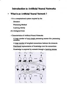
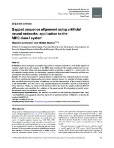
parking task was divided in three stages: to search for a parking space location; to adjust the vehicle position to allow a correct parking; to control the parking manoeuvre execution. While the vehicle moves along the road searching for a vacant place, an environment map is elaborated considering the sensorial input data. When a parallel parking space with enough size is located, the system estimates the beginning manoeuvre position and moves the vehicle up to this position. Once the vehicle is correctly positioned, the parking manoeuvre starts. This task is accomplished through the use of sinus based functions, as described in [15]), defining a soft path, as showed in Figure 2.
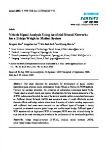
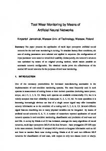
II. R ELATED WORKS AND MAIN CONCEPTS Studies relative to assistive systems and (semi)autonomous parking of vehicles have been done by some research groups and companies (e.g. BMW, Mercedes-Benz, Toyota, GMC) in the US, Japan, UK, Italy, Germany and France. Among them, one of the first outstanding studies was accomplished by INRIA researchers[7], [8], which implemented a control system used to park an adapted Ligier electric vehicle in an autonomous way. This vehicle was equipped with 14 sonar sensors and it was used a manually customized set of rules to accomplish the task. The Figure 1 shows the INRIA adopted vehicle and the parking model.
where φ(t) is the angle of the steering wheel at the instant t, v(t) is the speed of the vehicle at the instant t, T is the maximum duration of the parking manoeuvre, φmax is the maximum steering angle, and vmax is the maximum speed during the manoeuvre. The kφ = ±1 indicates if the parking space is on the left (−1) or on the right (+1) side, and kv = ±1 indicates the direction of the movement, assuming the value +1 to move forward and −1 to move backward. The values of A(t) and B(t) are estimated through the following equations: 0 ≤ t < t0 , 1, 0 ) 0 0 (3) A(t) = cos π(t−t T∗ , t ≤ t ≤ T − t , 0 −1, T − t < t ≤ T,
Fig. 2.
Parking path curve[8]
During all parking manoeuvre execution, the vehicle is controlled in an autonomous way using an iterative algorithm, and for each iteration, the speed and the steering wheel angle are adjusted using the following equations: φ(t) = φmax kφ A(t),
0 ≤ t ≤ T,
(1)
v(t) = vmax kv B(t),
0 ≤ t ≤ T,
(2)
B(t) = 0.5(1 − cos 4πt T ), t0 =
Fig. 1.
INRIA’s vehicle parking model[8]
The above mentioned system adopted the Ackerman kinematics model[1] to describe the vehicle control path. The 3 SEVA3D
– http://www.inf.unisinos.br/˜osorio/seva3d/
T −T 2
∗
,
0 ≤ t ≤ T,
T ∗ < T,
(4)
(5)
where T (duration of the manoeuvre) and T ∗ (duration of the curved part of the manoeuvre) are estimated based on the width (Di) and depth (Dw) of the parallel parking space. In order to become possible to measure in advance the parking space depth, it was necessary to install a barrier of moderate height close to the curb. The introduction of this artificial barrier turns possible to determine more precisely the parking space depth using the available sensors[7]. One of the advantages of this approach was the choice of sinus based functions to control the vehicle, producing softer movements,
instead of using a finite state automaton based on discrete states, which can causes abrupt state transitions and action changes. The drawbacks of this approach are: (i) the requirement of curb barrier installation, which restricts the practical application of this method on conventional streets; (ii) the great number of sonar sensors that must be installed around the vehicle (fourteen sensors); (iii) the limited application of this algorithm that works specifically in parallel parking tasks and needs to be manually coded. We aim to propose a new system that uses a small number of sensors, should be able to be used in conventional parking spaces, and also must allow a simple adaptation to different parking situations. The SEVA3D-N is the system we developed and we are improving in order to achieve these goals. III. A RTIFICIAL NEURAL NETWORKS Through the use of an abstract and simplified model of human neurons, is possible to develop a neural simulator capable to: classify, generalize and learn how to classify and approximate functions. One of the most used neural learning models is the so called Multi-Layer Perceptron (MLP) with Back-propagation learning algorithm[16]. Some improved versions of the original Back-Propagation algorithm were developed in the few past years, and the RPROP algorithm[17] became an interesting choice among them. The RPROP algorithm performs a direct adaptation of the weight step (learning rate) based on local gradient information. To achieve this, each weight has its individual update value ∆ij , which solely determines the size of the weight update. This adaptive update-value evolves during the learning process based on its local sight of the error function E, according to the following learning-rule[17]: (t−1) ∂E (t) ∂E (t−1) + ∗ ∂w >0 , if ∂w η ∗ ∆ij ij ij (t) (t−1) (t) (t−1) ∂E ∂E (6) ∆ij = ∗ ∂wij < 0 η − ∗ ∆ij , if ∂wij (t−1) ∆ij , else where 0 < η − < 1 < η + ,
∂E ∂wij
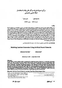
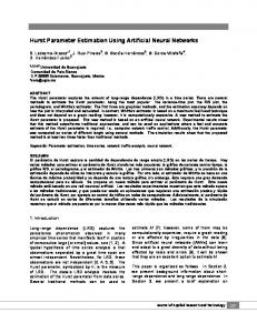
Implements sonar sensors similar to real sensors, including the presence of noise in the model; • Accomplishes the autonomous vehicle control, parking in a parallel parking space independent of the presence or absence of other previously parked cars; • Implements a robust control system accepting different starting positions, with a distance between the car and the curb ranging from 2 to 4 meters; • Accomplishes automatic adjustments of the vehicle position, if the vehicle is too close (or too far) from the parked cars, doing this before beginning the automatic parking manoeuvre (considers too close when the side by side distance is smaller than 30cm); • Allows the visualization of the parking manoeuvre from virtually anywhere in the 3D virtual environment; • Accomplishes the reversal parking manoeuvre, exiting the vehicle from the parking space in an automatic way. The major advantage of SEVA3D-N related to the SEVA3D-A is the fact that using an artificial neural network we do not need to manually code vehicle control rules (FSA), once the control system is obtained by training a neural net. We just need to show some examples of parking manoeuvres execution and the system will automatically adapt the network parameters, learning to autonomously park the vehicle. Both simulators, SEVA3D-A and SEVA3D-N, were able to correctly control the vehicles in parking manoeuvres, as presented in experimental results section. The Figure 3 shows a diagram of the SEVA3D modules. The main components of the SEVA3D simulator are: •
is the partial derivative of (t−1)
the error function for the weight wij , and ∆ij is the last weight update. The Artificial Neural Network simulator used in our experiments was the Stuttgart Neural Network Simulator - SNNS4 . It is a free software, and a quite complete neural network simulator that have several additional tools that allow us to create scripts and execute learning and simulation tasks in batch mode. The SNNS facilities also simplify the analysis of the obtained results and creation of graphic plots.
Fig. 3.
SEVA3D modules
IV. SEVA3D SIMULATOR The SEVA3D-A Simulator (controlled by a finite state automaton) possesses several improvements related to the original SEVA (2D), among which it can be emphasized the following main features: • Uses a 3D environment and 3D simulated sensors obtaining more realistic simulations; 4 SNNS
– http://www-ra.informatik.uni-tuebingen.de/SNNS/
Perception module: measures the distance from obstacles based on a sonar sensor simulation (see Section IV-B); Action module: sends action commands to vehicle actuators, defines the direction (forward, backward), the speed (gas pedal control) and the car orientation (steering wheel rotation) (see Section IV-D); Kinematics module: uses the Ackerman model to estimate the vehicle trajectory (simulation), considering vehicle direc-
tion, speed and steering wheel angle defined by the Vehicle Action Module (see Section IV-C); FSA control module: receives sensor data from the perception module and sends actions to the action module, using a Finite State Automaton to control the parking manoeuvre (see Section IV-E); Neural control module: receives sensor data from the perception module and sends actions to the action module, using an artificial neural network to control the parking manoeuvre (see Section IV-F). A. SimRob3D Simulation Tool The implementation of SEVA3D uses the SimRob3D simulation tools[13], [14], previously developed by our group. The SimRob3D tools main characteristics are: to provide 3D environment visualization tools used in simulations, and to provide customizable mobile robots simulation tools. The 3D environment objects can be modeled using different commercial or free 3D modeling software, and allows to detail the different elements present in the environment (objects - robots, vehicles, streets, buildings; lights and textures), resulting in a high level of realism in the simulations. The SimRob3D tools also include different sensorial (infrared and sonar sensors) and kinematics models (Ackerman and Differential models), which can be used to customize the simulated robots. SimRob3D tools provide only a set of methods used to read data from sensors and to send commands to actuators, updating the robot position in the simulated environment. SimRob3D needs an external robot control module, since their main goal is only to provide facilities to model the robots (defining sensors and actuators) and to provide a simulated interface between the robots and the environment. The external controller is a separated module from SimRob3D, in our case provided by SEVA3D. The interface between these two softwares is accomplished by DLL (dynamic linked library) calls. So, the SimRob3D API (Application Programming Interface) supplies an interface that separates world interaction from the robot control mechanisms. SEVA3D uses SimRob3D facilities to define the environment, vehicle, sensors and actuators, implementing its own vehicle control modules (FSA and neural control modules). An interesting characteristic of this coupled system is that the controller does not possesses direct access to any information from the environment, the only available information is the one provided by the vehicle sensors through DLL calls. B. Sensors Model Sonars are an interesting type of distance sensor used in robotic applications, because they can estimate with a reasonable precision the distance from objects positioned near to them. Sonars can be used to perceive the environment objects and obstacles, and they offer a good precision/price rate related to other distance measuring methods[18]. The simulated sonar sensors[1] allow to estimate the distance between the vehicle and the obstacles present in the environment: other cars and the edge of the sidewalks.
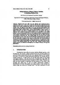
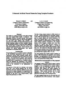
The five sensors used were distributed in strategic positions of the vehicle, as showed in Figure 4.
Fig. 4.
Distribution of the sonar sensors around the vehicle
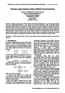
In our experiments sensors were put only in one side of the vehicle, because all experiments were developed in order to park the vehicle in parallel parking spaces located on the right side of the car, which is a typical situation in twoway streets. Sensors V[2] and V[3] were positioned with a certain inclination related to the ground, so it was possible to detect the curb. The SEVA3D allows to configure other distributions of the sensors, but in this paper the discussion is focused only to this kind of vehicle configuration. The SimRob3D sonars are simulated through the definition of a conical section of the virtual space, where the objects which remain inside this volume can be detected. The intersection between objects and the sonar cone volume (perceptual space) is detected using a stochastic approach. Several object detection lines (rays) are generated from the position of the sensor directed according to the sonar spatial orientation, remaining inside the sonar cone volume. A RayCast5 technique was used to generate rays, that are randomly distributed in the sonar cone volume. If any of them collide (intersect) with some object polygon, the distance from the sensor until the collision point is informed. Due to the stochastic nature of the measured distances, a temporal window method[20] was adopted to represent the data obtained from sensors. The defined temporal window has a length of 10 samples. This technique is also commonly used to deal with real sonar sensors data. Besides the sonar sensors, sometimes it was also necessary to use an odometer. The odometer was used only to verify if the parking space is enough to allow the correct parking of the vehicle when there are no other parked cars available to be used as reference points. This situation occurs only when there are large empty spaces. C. Kinematics Model The movement of the vehicle respects the Ackerman kinematics model[1], which was also the model adopted in the precursor work developed at INRIA[21]. In this model a simulated vehicle is represented by a rectangular volume supported by four wheels divided in two axes, where the back wheels are attached to a fixed axis and the front wheels can be turned, controlling them through the steering wheel[18]. The Figure 5 shows the elements of the kinematics model. 5 RayCast is a computer graphic technique that simulates the physical effects associated with the propagation of light rays[19]
Fig. 6. Fig. 5.
Kinematics model
The vehicle’s location (position and orientation) relative to some reference coordinate system is denoted as q = (x, y, θ)T where x = x(t) and y = y(t) are the coordinates of the rear axle midpoint, θ = θ(t) is the orientation of the vehicle, and t is time. The motion of the vehicle is described by the following equations[8]: x˙ = v cos φ cos θ, y˙ = v cos φ sin θ, (7) ˙ θ = Lv sin φ,
where φ = φ(t) is the steering angle, v = v(t) is the locomotion velocity of the midpoint of the front wheel axle, and L is the wheel base. The steering angle and locomotion velocity are two control commands (φ, v). Eqs. 7 correspond to a system with non-holonomic constraints because they involve the derivatives of the coordinates of the vehicle and are non-integrable[22]. D. Vehicle Control The vehicle is controlled in SEVA3D by simulated actuators. These actuators control the vehicle speed (accelerate/break) and steering wheel rotation. So, the vehicle displacement is obtained in the simulator sending commands to actuators which control the speed (v) and rotation of the steering wheel (φ). Differently of the model adopted in SEVA2D, whose parameters are not directly related to real world measures (distance was measured in pixels), the parameter values adopted in SEVA3D are quite realistic. As for example, during the parking manoeuvre in SEVA3D the speed can be set with values ranging from 0 (stopped) to 80 (very fast). When the vehicle needs to move backward the speed is set to a negative value. To change the vehicle orientation, the steering wheel angle (φ) can be set with values ranging from 0 and 35, that corresponds directly to the rotation angle to the left of the steering wheel. When the vehicle needs to turn to the right the angle φ is set to a negative value. E. Finite State Automaton Control In SEVA3D-A, the vehicle control in an autonomous parking task is accomplished by a Finite State Automaton (FSA). The Figure 6 shows the diagram of the finite state machine used to control the vehicle, and therefore this successful FSA was also used to be learned by an artificial neural network. The following states were defined:
Automaton states
Stopped: automaton initial and final state; Searching for parking space: first state of the parking manoeuvre, when the vehicle moves in a straight forward direction, searching for a free parking space. If a possible parking space is found the FSA state changes to Positioning outside; Positioning outside: the vehicle moves forward in order to reach a correct position to start entering in the parking space, usually aligning side by side with the next parked car (the odometer can be used in the absence of parked cars). This state is also used to verify if the parking space is adequate. If the space is too small, the state returns to Searching for parking space. If the space is large enough, the state changes to Entering; Entering: the car starts to move backward and the steering wheel is turned to the right, so in this way the vehicle starts to enter in the parking space. The φ and v values are set to empirically predefined values. When the sensor V[2] (Figure 4) detects the sidewalk curb the state changes to Positioning inside; Positioning inside: in this state, the vehicle continues to move backward, but the steering wheel is turned to the left. When the sensor V[3] detects the sidewalk curb or the sensor V[1] detects a close obstacle (distance under 30cm) the state changes to Aligning; Aligning: in this state, the vehicle is moved in order to reach an adequate distance from the cars parked ahead and behind it. After the alignment is done, the state changes to Stopped and the manoeuvre is terminated with success. F. Neural control The results obtained with the control based on a manually specified FSA, adopted in SEVA3D-A, motivated us to study other alternatives to the parking control task knowledge acquisition. The FSA creation process was difficult, and the rule codification was an arduous task and besides that the final result does not guarantee a great robustness to the system. As the control system was hard coded, the FSA needs a fine tuning every time we have some change in sensors and actuators behavior (e.g. input noise, imprecise actuators), and also if an unexpected situation occurs. We looked for a practical solution that should be capable to automatically learn how to control the vehicle. The adopted solution was the use of artificial neural nets (ANNs)[16] with supervised learning, which are capable to adapt themselves to different situations. The ANNs can learn how to control the vehicle in a parallel parking task from a set of practical examples: we just need to show how to park the vehicle. This approach is
very interesting because it increases the possibility of success when the simulated control system will be transposed to the real vehicle. The first step was to create the parking examples data set to be employed in the ANN learning. The SEVA3D-A simulator was adapted in order to generate a log file, containing records of: the sensors state, the FSA state and the commands sent to the vehicle actuators (speed and steering wheel angle). The obtained file can be used to train a neural net, and it was expected that the resulting ANN could be able to reproduce the FSA behavior. The initial experiments worked fine and later SEVA3D was also used to generate a new set of parking task examples, with the vehicle being controlled by a human instead using the autonomous control system. The ANN adopted model was a Jordan-Net[23], a modified version of Multi-Layer Perceptron (MLP) nets[20] with recurrent inputs. The learning algorithm implemented was the Resilient Propagation[17]. This network was used in the following way: a set of inputs are used to indicate the current state of the network (representing the active FSA state) and another set of outputs are used to indicate the next state of the network (the FSA state in the next cycle). The next state indicated by the network outputs can be the same as in the current state or it can be changed in order to assume a new network state. The network state changes occur in function of their inputs represented by the sensors plus the current state. So, the neural net receives as inputs the sensors data and the current state (Figure 7) and based on this information decides if the current state remains the same, or if it is time to change to a new state.
Fig. 7.
Artificial neural network model scheme
Then the next state (current or new), indicated by the network outputs, is re-injected in the network inputs. This makes this model similar to the ANN model proposed by Jordan[23], where the network outputs are re-injected in the inputs through a recurrence known as context units. Using these context units we provide the information about the current state of the network (simulated FSA). The Table I shows the main ANN parameters used in our simulations. For a complete description of these parameters, see the SNNS manual. The neural input variables used were: the data from the five sonar sensors, the odometer and the current state of the parking process. In the network output is obtained the actuators activation commands (speed and steering wheel rotation), as well as the indication of the next state of the parking process. This network output information allows to simulate a FSA, controlling the actuators and the
TABLE I N EURAL NETWORK PARAMETERS Parameter ANN model Learning algorithm Number of input units Number of hidden units Number of output units Activation function Starting learning rate Maximum learning rate Weights initialization Maximum of generations
Value MLP - Jordan RPROP 12 5 12 Act Logistic 0.001 0.1 [0.001; 0.001] 1000
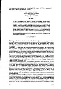
FSA state, which can be changed according to the progress of the parking manoeuvre. The Figure 7 presents the scheme of the ANN inputs and outputs used in SEVA3D-N. The states and actions were coded on a “1-of-N” basis in the learning database used to train the neural network. The neural inputs and outputs were defined as follows: • Inputs: current state (6 states = 6 binary inputs, one input for each state); state of the sensors (5 sensor = 5 numerical inputs normalized between 0 and 1); odometer (1 numerical input); • Outputs: speed (3 states with previously fixed speeds = 3 binary outputs: forward, backward and stopped); steering wheel angle (3 possible predefined angle positions = 3 binary outputs: Turn to the left, Straight forward and Turn to the right); next state (6 binary outputs). It should be pointed out that it is very important to know the current state to allow a correct interpretation of the sensors (same situation, different actions), for example: (i) When searching for a free parking space, if lateral sensors indicate the proximity of parked cars then this indicates that we should continue to move forward until a parking space is found; (ii) When entering in a parking space after the vehicle was positioned outside of it, if the lateral sensors indicate the proximity of a parked car (exactly as in the previous situation) then this indicates that we should start to move backward and turn the steering wheel to the right. So, correct state transitions are very important to accomplish the autonomous parking task. In our experiments we noticed that the neural net was perfectly capable to learn state transitions (next state outputs were correctly generated). Once the neural learning phase is finished, it is capable of accomplishing the vehicle parking task autonomously without any human intervention. V. I MPLEMENTATION The SimRob3D simulation tools[13], [14] were used to create the virtual environment and to interface the vehicle devices with the SEVA3D autonomous controller implementation. The virtual environment was modeled, creating 3D models of the road and parked cars, and also the model of our autonomous vehicle. The Figure 8 shows an image of the virtual environment modeled. The model of the vehicle used to accomplish the parking task is a reproduction of a real Mini-Baja Buggy available
Fig. 10. Fig. 8.
Virtual environment visualization
in our research laboratory. This vehicle was developed by the GPVA Research Group at Unisinos. The real vehicle was automated and now it can be controlled from remote devices, like cell phones (see available videos in the GPVA web site). The Figure 9 shows the actual vehicle used as model of the virtual autonomous vehicle. At the present time we are working on the real vehicle instrumentation, adding sonar sensors, and a real world test is planned soon using the SEVA3D controller to control the real vehicle.
(a) Real vehicle Fig. 9.
(b) Simulated vehicle Automated Mini-Maja vehicle
The SEVA3D simulator implements a discrete integration of the model described in the Eqs. 7. The FSA implementation, used to control the simulated SimRob3D vehicle movement, was developed in “C” language. In order to follow the progress of the parking manoeuvre, the user can visualize the simulated environment using a virtual camera. Besides that a status window exhibits information about the simulation, including: the FSA current state, the sensors data, the vehicle speed and steering wheel angle, the absolute vehicle position and orientation, and the odometer value. The Figure 10 shows the window containing all these information. The SEVA3D implementation was validated through several preliminary tests. It was also verified that the simulated model behavior was quite similar to the reality. In the next section are presented the main experimental results obtained with this system. VI. E XPERIMENTAL RESULTS The learning database was created with 2166 examples, (1083 for the learning and 1083 for the generalization test),
Status information window
each one with 12 inputs and 12 outputs. The Table II shows the results obtained in the ANN learning for 10 different experiment runs. The first column (E) is the experiment identifier, the second and third columns shows, respectively, the mean square error (MSE) and the correct classification rate (Hits) in the learning database, and the two last columns shows the MSE and the correct classification rate (Hits) in the generalization test database. The last two lines of the Table II shows the mean (µ) and the standard deviation (σ) of all accomplished experiments. TABLE II R ESULTS OBTAINED IN THE SIMULATIONS E 01 02 03 04 05 06 07 08 09 10 µ σ
Learning MSE Hits 1.0482e-02 93.26% 1.8281e-02 78.67% 1.0415e-02 90.86% 1.9093e-02 89.47% 1.8791e-02 90.58% 1.6726e-02 79.04% 1.4022e-02 87.53% 1.4551e-02 93.26% 1.3445e-02 91.23% 6.2535e-03 84.49% 1.4206e-02 87.84% 4.2174e-03 5.40%
Generalization MSE Hits 2.1188e-02 93.17% 2.6644e-02 92.43% 2.5437e-02 90.30% 2.4292e-02 88.09% 2.6284e-02 89.10% 2.5679e-02 84.49% 2.1959e-02 87.17% 2.5646e-02 95.84% 2.7894e-02 81.35% 2.5490e-02 88.73% 2.5051e-02 89.07% 2.0625e-03 4.23%
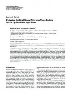
The generalization test was performed for each 10 epochs, and the average best epoch was 382. The achieved learning performance was 89.07% of correct answers. A correct answer occours when all outputs are correct, considering a score threshold of 0.4. The Figure 11 shows the neural output error (MSE) curve evolution during the learning, related to the learning data (darker line) and the generalization test data. The examples that generated an incorrect network output were analyzed and in all cases it was noticed that the wrong answers don’t cause problems in the FSA state transitions. The trained ANN was perfectly capable to change from the current FSA state to the next FSA state with no errors. This is very important once correct FSA state transitions are critical to obtain a successful parking manoeuvre. In experiments of the Table II, SEVA3D was capable to correctly park the vehicle, with an average distance from the curb of 26.16cm and a standard deviation of 5.92cm. This demonstrates that the implemented system is safe and robust
future we plan to implement SEVA3D-N in a real vehicle, an automated mini-Baja Buggy available in our research laboratory. The SEVA3D neural network will be adapted (trained) to use the new hardware (real sonar sensors) and the system will be evaluated in real world conditions. R EFERENCES
Fig. 11.
Progress of the neural learning
to control vehicles in parallel parking tasks execution. The Figure 12 shows an example of parking manoeuvre6 .
Fig. 12.
Parking manoeuvre
VII. C ONCLUSIONS AND PERSPECTIVES This work main goal was to develop a simulator for autonomous control of vehicles in parallel parking tasks. The proposed system should be able to create a realistic model of the real world application, so it was implemented a simulation tool situated in a 3D environment, the SEVA3D. This system includes a 3D model of the vehicles and obstacles, and it also includes a 3D model of sonar sensors. The experimental results, accomplished with SEVA3D-A (control based on a FSA) and SEVA3D-N (control based on an ANN), demonstrated that the control system possesses the capacity to correctly control the vehicle. The main objective of the control system was achieved with success: to park vehicles in an autonomous way, not colliding against obstacles present in the environment. In order to validate the SEVA3D vehicle control module, several experiments were accomplished with visual and numerical evaluations. This experiments allowed to verify that the vehicle was correctly controlled in different situations, demonstrating that the proposed method is stable, safe and robust. Although the experimental results were very good, we are still planning to improve SEVA3D/SimRob3D simulation model. The implementation of a new version of SEVA3D is being considered in order to include a more realistic physical simulation tool. We are considering to add rigid body dynamics simulation extensions, allowing to simulate force, torque, friction, gravity, terrain slopes, etc. In the near 6 Some videos demonstrating the SEVA3D parking manoeuvre are available in http://www.inf.unisinos.br/˜osorio/seva3d/
[1] G. Dudek and M. Jenkin, Computational Principles of Mobile Robotics. Cambridge, UK: Cambridge Univ. Press, 2000. [2] F. J. Heinen, Rob´otica Autˆonoma: Integrac¸a˜ o entre Planificac¸a˜ o e Comportamento Reativo. S˜ao Leopoldo, RS, Brazil: UNISINOS Editora, Nov. 1999. [3] D. Pomerleau, “Neural network based autonomous navigation,” Vision and Navigation - The CMU Navlab, 1990. [4] P. Batavia, D. Pomerleau, and C. Thorpe, “Applying advanced learning algorithms to alvinn,” Carnegie Mellon Univ. (CMU), Pittsburgh, PA, Technical Report CMU-RI-TR-96-31, 1996. [5] H. W. Stone, “Mars pathfinder microrover - a small, low-cost, lowpower spacecraft,” in Proc. AIAA Forum on Advanced Developments in Space Robotics, Madison, WI, Aug. 1996. [6] M. Lemonick, “Dante tours the inferno,” Time Magazine - Time Domestic/Science, vol. 144, no. 7, 1994. [7] I. E. Paromtchik and C. Laugier, “Autonomous parallel parking of a nonholonomic vehicle,” in Proc. IEEE Int. Symposium on Intelligent Vehicles (IV), Tokyo, Japan, Sept. 1996, pp. 13–18. [8] C. Laugier, T. Fraichard, I. E. Paromtchik, and P. Garnier, “Sensor based control architecture for a car-like vehicle,” in Proc. IEEE/RSJ Int. Conf. Intelligent Robots and Systems (IROS), Victoria, Canada, Oct. 1998, pp. 165–185. [9] F. S. Os´orio, F. J. Heinen, and L. Fortes, “Autonomous vehicle parking using finite state automata learned by J-CC artificial neural nets,” in Proc. VI Brazilian Symposium on Neural Networks (SBRN), vol. 1. Porto de Galinhas, PE, Brazil: IEEE Press, 2002. [10] ——, “Controle inteligente de ve´ı-culos autˆonomos: Automatizac¸a˜ o do processo de estacionamento de carros,” in Anais do Seminco, Blumenau, SC, Brazil, Oct. 2001. [11] M. R. Heinen and F. S. Os´orio, “Estacionamento de um ve´ıculo de forma autˆonoma simulado em um ambiente tridimensional real´ıstico,” in Anais do Seminco, Blumenau, SC, Brazil, Oct. 2005, pp. 56–65. [12] C. Kelber, C. R. Jung, F. S. Os´orio, and F. J. Heinen, “Electrical drives in intelligent vehicles: Basis for active driver assistance systems,” in Proc. IEEE Int. Symposium on Industrial Electronics (ISIE), vol. 4, Dubrovnik, Croatia, 2005, pp. 1623–1628. [13] F. J. Heinen and F. S. Os´orio, “HyCAR - a robust hybrid control architecture for autonomous robots,” in Proc. Hybrid Intelligent Systems (HIS), vol. 87. Santiago, Chile: IOS Press, 2002, pp. 830–840. [14] F. J. Heinen, “Sistema de controle h´ıbrido para robˆos moveis autˆonomos,” Master’s Thesis - Applied Computing, Universidade do Vale do Rio dos Sinos (UNISINOS), S˜ao Leopoldo, RS, Brazil, 2002. [15] R. Murray and S. Sastry, “Steering nonholonomic systems using sinusoids,” in Proc. 29th IEEE Int. Conf. Decision and Control (CDC), New York, Dec. 1990, pp. 2097–2101. [16] D. Rumelhart, G. Hinton, and R. Williams, Learning Internal Representations by Error Propagation. Cambridge, MA: MIT Press, 1986. [17] M. Riedmiller and H. Braun, “A direct adaptive method for faster backpropagation learning: The RPROP algorithm,” in Proc. IEEE Int. Conf. Neural Networks (ICNN), San Francisco, CA, Mar. 1993, pp. 586–591. [18] G. A. Bekey, Autonomous Robots: From Biological Inspiration to Implementation and Control. Cambridge, MA: MIT Press, 2005. [19] J. D. Foley, Introduction to Computer Graphics. Addison-Wesley, xxviii, 1994. [20] S. Haykin, Neural Networks: A Comprehensive Foundation, 2nd ed. Upper Saddle River, NJ: Prentice-Hall, 1999. [21] P. Garnier, T. Fraichard, C. Laugier, I. Paromtchik, and A. Scheuer, “Motion autonomy through sensor-guided manoeuvres,” in Proc. IEEE/RSJ Int. Conf. Intelligent Robots and Systems (IROS), Kyongju, Korea, Sept. 1999. [22] J. C. Latombe, Robot Motion Planning. Boston, MA: Kluwer Academic Publishers, 1991. [23] J. Ludik, W. Prins, K. Meert, and T. Catfolis, “A comparative study of fully and partially recurrent networks,” in Proc. IEEE Int. Conf. Neural Networks (ICNN), vol. 1, Houston, TX, 1997, pp. 292–297.