Pettis and Hansen reported an 8% reduction in execution time for procedure .... such a compound node, we guarantee that the procedures will stay close to.
Using Cache Line Coloring to Perform Aggressive Procedure Inlining Hakan Aydın David Kaeli Department of Electrical and Computer Engineering Northeastern University Boston, MA, 02115 {haydin,kaeli}@ece.neu.edu
Abstract Memory hierarchy performance has always been an important issue in computer architecture design. The likelihood of a bottleneck in the memory hierarchy is increasing, as improvements in microprocessor performance continue to outpace those made in the memory system. As a result, effective utilization of cache memories is essential in today’s architectures. The nature of procedural software poses visibility problems when attempting to perform program optimization. One approach to increasing visibility in procedural design is to perform procedure inlining. The main downside of using inlining is that inlined procedures can place excess pressure on the instruction cache. To address this issue we attempt to perform code reordering. By combining reordering with aggressive inlining, a larger executable image produced through inlining can be effectively remapped onto the cache address space, while not noticeably increasing the instruction cache miss rate. In this paper, we evaluate our ability to perform aggressive inlining by employing cache line coloring. We have implemented three variations of our coloring algorithm in the Alto toolset and compare them against Alto’s aggressive basic block reordering algorithms. Alto allows us to generate optimized executables, that can be run on hardware to generate results. We find that by using our algorithms, we can achieve up a 21% reduction is execution runtime over the base Compaq optimizing compiler, and a 6.4% reduction when compared to Alto’s interprocedural basic block reordering algorithm.
I.
Introduction
Past research has demonstrated that memory hierarchy performance is a critical factor in obtaining good system performance. There has been a considerable amount of work studying both hardware and software solutions to achieve better instruction cache performance. 1
In software engineering, large applications are often decomposed into smaller problems, which are coded as procedures. Procedure calls have been shown to be one of the most expensive source language statements [5]. Moreover, a considerable percentage of all dynamic instructions are due to implementing proper procedure calls and returns [4]. Procedural programming interferes with other optimizations, such as register allocation, constant propagation and dead code removal. We are presently studying how to address some of these limitations with the aid of profiling. One way to address the problems associated with procedure calls is to use procedure inlining. Inlining replaces a procedure call at the call site by the procedure body itself. Inlining can have both a positive and negative effect on performance. Inlining a procedure eliminates the calling overhead associated with a procedure call, though generally increases code size which may increase the number of instruction cache misses. When inlining a procedure, the optimizer needs to decide whether the removal of the call and return overhead will be more beneficial than the loss of cycles due to an increase in the instruction miss rate. Most optimizers use some form of the the following heuristics to select which procedures to inline [3]. A procedure is an inline candidate if: • a procedure’s body is small (i.e., inlining it may actually reduce the executable image size), • a procedure is called from only one call site, or • a procedure is called frequently (e.g., inside a loop). The benefits of inlining are not just removing procedure call and return sequences. Inlining allows other optimizations to be done more aggressively, such as register allocation, code scheduling, common subexpression elimination, constant propagation and dead code elimination. But inlining procedures is a tradeoff, and is not for free. As code size increases, there will be added pressure on the instruction cache. Reordering program units on the cache space is one of the most effective optimization techniques to remedy the negative side-effects associated with inlining. Code layout can be performed at different granularities, and can be applied both within a procedure or between procedures. In this paper we apply procedure reordering. Research shows that code layout can significantly increase performance, especially when guided by profile information. Pettis and Hansen reported an 8% reduction in execution time for procedure reordering, 12% for basic block reordering and 15% when both of these profile-driven techniques are applied together [6]. The algorithm we apply is also driven by profile information. To implement out our coloring algorithms we chose Alto [12] as our framework. Alto (A link-time optimizer for the DEC Alpha) is a tool developed at the University of Arizona for optimizing Alpha executables. One of the reasons that we chose Alto is its ability to perform aggressive procedure inlining. We have implemented our cache coloring algorithms in Alto to see if our aggressive inlining can greatly benefit from our cache coloring algorithms. We we develop three different schemes: 1. procedure coloring (keeping procedures intact and treating procedure boundaries as the granularity during reordering), 2. procedure coloring, with hot/cold optimization (allowing two popular procedures to overlap, using only their hot regions as the granularity during reordering), and 3. procedure coloring and basic block reordering, (same as scheme 2, with an additional step of reordering basic blocks in the hot region). The Alto framework already provides a rich set of tools for performing inlining and basic-block level code reordering. Our goal is to provide code reordering algorithms that specifically target aliasing caused by inlined procedures. We have been able to show that by using our new algorithms, 2
performance is improved significantly. We also believe that our algorithms will result in a reduction in compilation time1 . Note that in our base algorithms we work with procedures, whereas Alto reorders using basic blocks. This paper is organized as follows. Section II. discusses previous work on inlining and reordering, Section III. describes the cache coloring algorithm used, Section IV. describes variations of the cache coloring algorithm that we implemented, Section V. describes how the algorithm was implemented in Alto, Section VI. presents runtime results, and finally Section VII. summarizes the paper.
II.
Related work
In [7], Hwu and Chang present an algorithm for applying inlining, basic block reordering and procedure reordering. They do not use a coloring approach for procedure reordering, but instead use a depth-first traversal of the procedure call graph and place the procedures in depth-first order (this same ordering is used by the Compaq native C compiler). Pettis and Hansen proposed basic block and procedure reordering algorithms and reported a decrease in execution time of 15% when both algorithms were used together [6]. Their procedure reordering algorithm uses a greedy algorithm which is based on the weight of the call graph edges, and uses a closest-is-best scheme to keep frequently accessed program units close together. McFarling investigated a basic block reordering algorithm based on loops in a program. His algorithm tries to generate call trees, of size less than the size of the instruction cache, by examining the loop constructs in the code [11]. Gershony et al. studied different reordering algorithms and investigated cache miss rates using several different cache configurations and benchmarks on both Alpha and IA32 architectures [9]. Lee also studied the instruction cache effects of different code reordering algorithms by using simulation [10]. He reports that code reordering algorithms are more important in architectures with longer line sizes. Ayers et al. developed an aggressive inliner which can also employ cloning. They report a peak speedup of 200% for some SPEC benchmarks[8].
III.
Cache Line Coloring
Procedure reordering is used to create a program layout that will reduce the number of instruction cache conflicts. There have been a number of procedure reordering algorithms proposed. Procedure mapping using cache line coloring differs from other algorithms by taking into account the cache size, cache line size, cache associativity, and procedure size. The basis of the cache coloring algorithms used in this paper was proposed by Hashemi et al. [1]. The goal of the coloring algorithm is to reduce the number of instruction cache conflict misses that occur during the execution of a program. The basic idea behind the algorithm is to place procedures in the cache in such a way that, the procedures that interact with each other frequently will not overlap in the cache address space. For each procedure in the code, the algorithm keeps track of the colors assigned to that procedure and the unavailable color set of the procedure. This set is defined as the cache lines occupied by the neighbors of the procedure in the call graph. When mapping a procedure, this unavailable set is checked to see if the new mapping is creating a cache line conflict. If such a conflict is found, the procedure under consideration may be shifted in the cache address space, until cache conflicts do not occur. The algorithm uses heuristics to fill the gaps that are created in the code. 1 While this is a goal of our work, we chose not to evaluate compilation time, given that this metric is not one of the design objectives of the Alto framework.
3
For cache line coloring, the algorithm first starts by building the procedure call graph. The edges of the graph are undirected, and their weights are determined by summing up the calls that occur between the procedures connected by the edges. The next step is to determine the edges that will be processed by the algorithm. To do this, the algorithm uses heuristics to classify the edges as popular or unpopular, based on their execution frequency. After this classification, the algorithm processes each popular edge, starting from the most frequently executed edge. During this phase, the algorithm can encounter four different cases: Case I: The first case occurs when both procedures that are connected by the edge are unmapped. In this case, the algorithm forms a compound node and places these two procedures in the compound node next to each other. The first procedure in the compound node will be the larger of the two procedures. By creating such a compound node, we guarantee that the procedures will stay close to each other in the layout. Case II: In the second case, the edge that is being processed is between two procedures that are in two different compound nodes. In this case, the two compound nodes are merged together into a single compound node. The smaller compound node is appended to the larger one. The algorithm uses heuristics to decide on how to order the procedures in the compound node. After the procedures are placed, the compound node is examined for any cache conflicts. If the algorithm finds a cache conflict, the smaller compound node is shifted away from the larger compound node until there are no conflicts. If the cache conflicts can not be avoided by shifting the compound node, the original mapping is restored. Case III: Another possible case is when the edge connects two procedures, where one procedure is in a compound node and the other has not yet been mapped. In this case, the algorithm appends the unmapped procedure to the compound node. The new procedure is placed to the left or right side of the compound node, depending on the distance to the procedure that is in the compound node. After the new procedure is placed, the algorithm checks for color conflicts and moves the procedure in the cache address space to avoid conflicts. Case IV: The last case occurs when the edge under consideration connects two procedures that are mapped in the same compound node. In this case, the algorithm checks for color conflicts in the compound node. If any color conflicts are found, the procedure that is closer to either end of the compound node is moved past the end of the compound node, creating a gap. If color conflicts still exist, the algorithm tries to shift this procedure away, until all color conflicts disappear. If no conflict-free mapping can be found, the original mapping is restored. All the popular edges2 are processed by this algorithm in this manner. After this step of the algorithm is complete, we may have a set of one or many disconnected compound nodes. To fill in the gaps between these nodes, the unpopular procedures3 are used. Cache conflicts are not considered for the unpopular procedures, simply because they are executed very infrequently compared to the popular procedures.
IV.
Variations of the coloring algorithm
The layout algorithm described in Section III. keeps the procedure bodies intact. We have also implemented a variation of this algorithm, which allows splitting procedures. The algorithm operates as follows: 1. Before building the undirected procedure call graph, our algorithm analyses the basic blocks of each procedure in the layout. Based on profile information, the algorithm marks each basic block 2 edge 3 these
popularity is defined by the frequency a graph edge is traversed include infrequently activated or unactivated procedures in the profile
4
as hot or cold. In our current implementation, all the activated basic blocks of a procedure are marked as hot and the remaining ones are marked as cold. 2. Next, we divide the procedure into two regions, one containing all the hot basic blocks, and the other containing the remaining cold basic blocks. At this point, some procedures might still be kept intact, if all of its basic blocks were marked as all hot or all cold during the analysis. 3. The undirected procedure call graph is built next. An edge E in the UPCG can be of four different types. For two procedures A and B in the layout, an edge E can connect (A hot − Acold ), (Ahot − Bcold ), (Ahot − Bhot ) or (Acold − Bhot ). 4. Finally, the remainder of the algorithm operates as described in Section III., except in this case, there is an extra step for fixup of the branch instructions, since the layout was changed in the previous step. The idea behind our splitting algorithm is to have a denser group of hot regions in the layout. Splitting the procedures by using basic block count information causes the procedure size to decrease most often the time4 . This decrease in the procedure size allows the coloring algorithm to work with smaller units, which is likely to result in a reduced executable size. This is because the chance of having a gap created by the coloring algorithm increases with large procedure sizes (assigning cache line colors to procedures becomes increasingly hard with larger procedure sizes). Eliminating some procedures increases the probability of excluding the largest procedures. Splitting a procedure can also have a negative effect on performance. If the training input does not accurately characterize a program’s general runtime behavior (i.e., independent of input), splitting can hurt performance. If the analysis done for a layout generated by a training input marks some basic blocks of a procedure as cold and those basic blocks are frequently activated with the test input, there is an increased chance of instruction cache misses during execution. This happens since the algorithm will ignore attention to the color conflicts that might occur between the cold sets of the procedures. We actually observe this side effect of splitting the procedures in our results. This is always an issue for any profile-driven algorithm. One final version of procedure coloring that we implemented performs basic block layout within the hot blocks of each procedure. This layout is performed after each procedure is split into hot and cold regions. The basic block layout algorithm (also described in [2]) operates as follows: 1. We build a call graph of basic blocks. The edges of this call graph are then sorted by decreasing edge weights. 2. For each edge (E) encountered, the algorithm may encounter three different cases: Case I: If the basic blocks at the head and tail of the edge are both unmapped, we create a compound node containing these two basic blocks. Case II: If one of the basic blocks is mapped and the other unmapped, the algorithm checks the position of the mapped basic block b in its corresponding compound node. If the mapped basic block b is the head of its compound node C and the tail of the processed edge E, then the algorithm prepends the unmapped basic block to the compound node C. Similarly, if the mapped basic block is the tail of its compound node C and the head of the processed edge, then the algorithm appends the unmapped basic block to the compound node C. Case III: If the basic blocks of the edge being processed are both mapped into compound nodes, the algorithm checks for their position in their compound nodes. If the head basic block b 1 of the edge being processed is the tail of its compound node C1 and the tail basic block b2 of the 4 This
actually depends on the training input that is used to gather profile information
5
edge being processed is the head of its compound node C2 , then the compound nodes are merged into a single compound node C1 C2 . 3. After processing all edges in the graph, there might be several independent compound nodes, which are then merged together into a single compound node. The algorithm then processes the layout to enforce the new ordering. After this step, the algorithm patches the new layout, by creating and/or removing unconditionals and branches where necessary. Performing this layout algorithm within the hot blocks guarantees that the outcome of the frequently executed branch instructions will most likely follow their fall-thru paths. To summarize, we have implemented three different approaches to coloring. The first algorithm only applies procedure coloring, using the procedures as the granule for reordering. The second algorithm divides procedures into hot and cold set, and uses these smaller blocks as the reordering granule as input to the coloring algorithm. Finally, the third algorithm performs a basic block layout algorithm within the hot region, extending the procedure splitting and coloring optimizations done in previous algorithms.
V.
Implementation
We have implemented our cache line coloring algorithm in Alto [12]. Alto takes an executable and execution profile information as inputs, and then performs various optimizations and produces an optimized executable. The particular optimizations of interest in to us in Alto are inlining and code reordering. When performing inlining, Alto uses the following heuristics: • inline if this procedure is very small (i.e., if the call and return instructions will take up more space than the procedure’s body), • inline if the call site being processed is the only call site for this procedure, or • inline if the call site is activated very frequently and the resulting cache footprint does not exceed the instruction cache size. The decrease in execution time achieved with inlining alone with Alto is reported to be as much as 4.3%. Alto also performs interprocedural basic block layout which can be guided by profile information. If profile information is available, Alto tries to avoid cache conflicts by grouping the basic blocks into hot, cold and zero sets and applying the bottom-up positioning approach described by Pettis and Hansen [6]. Muth et al. report that using this basic block layout algorithm can decrease execution by 17% [12]. Our procedure reordering algorithm starts after Alto completes basic block layout, and before the scheduler is invoked. Since Alto performs interprocedural basic block reordering, a procedure’s basic blocks can be spread out all over the image space. However, one of the procedure mapping algorithm that we have implemented requires that procedures are kept as a whole. So, before our cache coloring algorithm starts, we first examine the layout created by Alto and merge all basic blocks associated with a single procedure together. After this phase, we have a sequence of procedures, with the basic blocks rearranged within a procedure, and with the hottest basic blocks at the beginning of each procedure in the image. The procedure splitting algorithm that we implemented, if activated, starts processing the layout at this point. The algorithm analyses each procedure by using the profile information and brings the activated and unactivated basic blocks together in the layout. 6
Similarly, if we activate our basic block reordering algorithm described in Section IV., it starts processing at this point, after the splitting phase. Therefore, the hot blocks that are fed into the procedure reordering algorithm will already have their basic blocks reordered by our basic block reordering algorithm described in Section IV. The rest of the algorithm proceeds as follows:5 1. The first step is to produce an undirected procedure call graph (UPCG), using Alto’s representation of edges between basic blocks. To do this, our algorithm checks all edges for each basic block in Alto’s call graph. Whenever we encounter a edge between two basic blocks, we update the UPCG, creating new edges when necessary. 2. The algorithm generates additional information about each procedure in the layout. Since our algorithm uses the cache parameters as input (i.e., cache size, line size, associativity), we determine the number of cache lines needed to hold each procedure in the final layout. 3. Next, we sort the UPCG edges in descending order. It is important that we process the edge with the highest execution count first, since our goal is to keep frequently executed procedures together. 4. We select the popular edges in the UPCG, using a simple heuristic. First, we sum up all the edge weights of all the UPCG edges. The popular edge set includes all the edges whose total execution count makes up 95% of all edge weights contained in the call graph. By using this heuristic, we include enough procedures for our algorithm to map intelligently, and yet we do not perform unnecessary work trying to map procedures with low execution counts. The unpopular procedures will be important later, since they are used to fill in the gaps created by the reordering algorithm. For the implementation of the algorithm, we created new data structures in Alto. The first structure maintains a list of the compound nodes. Each compound node keeps a pointer to the first and last procedure and the number of procedures in this compound node. Each compound node also maintains information on the starting cache line address and the total number of cache lines needed to hold it. We also maintain a list of procedures, in addition to the internal procedure representation already present in Alto. All dynamically allocated procedure nodes have a pointer to the compound node that it belongs to, and pointers to the previous and next procedures in its compound node. Procedure nodes also have the starting cache line color and size information. We map our representation of procedures to Alto’s representation by use of a hash table. After building these data structures, the algorithm starts processing the popular UPCG edges, and applies cache line coloring. After all popular edges are processed, we use the unpopular procedures to fill in gaps in the layout. To do this, we generate a list of gaps in the layout by examining each compound node and procedure. We then sort the gaps, and use a best fit placement algorithm for placing unpopular procedures into those gaps. We form a new compound node for the unpopular procedures that were not used to fill in gaps. In the final step, our algorithm reads the compound node list, analyzing the mapping data. For each compound node, it looks at the procedures in the compound node, starting from the first. If the algorithm decides that a procedure’s position should be adjusted in the cache, we compute the necessary alignment in terms of the number of instructions, and update the mapping to enforce alignment. This way, we generate an offset for each basic block in the final layout. This offset information is then used by the code generator for alignment purposes, as necessary. 5 The cache line coloring algorithm is described by using procedures as the basic units of processing. If our splitting algorithm is active, then the units of processing should be interpreted as hot blocks or cold blocks of procedures instead of procedures as a whole.
7
Benchmark gcc li go compress
Functions 2465 722 945 316
Basic blocks 77839 9213 16035 5092
Table 1: Characteristics of the benchmarks used Benchmark gcc li go compress
TCC 240.81 263.39 144.44 342.21
no. inlined 1143 173 359 113
TAlto−bbl 197.55 238.79 137.93 329.13
TAlto−cc1 188.82 238.16 129.19 326.41
TAlto−cc2 194.63 236.92 132.18 328.41
TAlto−cc3 193.09 236.65 131.12 326.81
Table 2: Execution times of SPEC95 benchmarks with four different types of optimization
VI.
Results
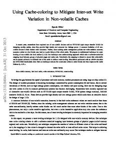
We have integrated our version of the procedure coloring algorithm into Alto and have evaluated its ability to remap applications compiled with aggressive inlining. We use four of the SPECint95 benchmarks to test the performance of our cache line coloring implementation. Table 1 summarizes the characteristics of the benchmarks that we have used. To evaluate performance, we first compiled the benchmark with the native Compaq cc compiler, with all optimizations turned on. Once an image is generated, we further optimize the code using Alto. We use different training and testing input, to look for sensitivity in our algorithms (as will be discussed later). We then run our cache line coloring algorithms and measure the execution times for the generated executables for each algorithm. For each benchmark, we ran the executables 10 times and recorded the best run time. Since Alto-generated executables can not be instrumented with a tool like ATOM, we were not able to measure instruction cache misses. We plan on using DCPI in the future to assess the number of instruction cache misses that actually occur in our executable. All compilations and execution run time tests were performed on a Compaq Alpha workstation with a 433 MHz Alpha 21164 processor (8K L1 instruction cache and 96K on-chip L2 cache) running Compaq Unix. Results are presented in Table 2 and Figure 1. In Table 2, the second column shows the execution time of the output file when compiled with Compaq cc compiler, the third column lists the number of procedures that were inlined by Alto, the fourth column shows the execution time when Alto applies inlining and interprocedural basic block reordering, the fifth column shows the execution time when Alto is run with our procedure coloring algorithm, the sixth column shows the execution time when Alto is run with our coloring and procedure splitting algorithms activated, and the seventh column shows the execution time of the output executable when Alto is run with coloring, procedure splitting, and intra-procedural basic block reordering (within hot blocks) activated. In Figure 1, we plot the percent decrease in execution time for our algorithms. All improvements are relative to execution time shown in Table 2 The bars labeled inter-bb show the reduction in execution time for Alto’s interprocedural basic block layout algorithm (computed as the ratio of column four over column two in Table 2) . The bars labeled cc show the decrease in execution time obtained by applying the procedure coloring algorithm. Cc/split shows the percent decrease in execution time obtained by using procedure coloring and splitting algorithms. Finally, the bars labeled cc/split/intra-bb show the performance obtained by applying all optimizations. 8
1
inter−bbl cc cc/split cc/split/intra−bbl
percent decrease in execution time
0.95
0.9
0.85
0.8
gcc
li
go
compress
Benchmark
Figure 1: Percent execution time decrease for our algorithms
As can be seen from Figure 1, both Alto’s basic block reordering and our cache line coloring implementations provide a substantial benefit over the Compaq cc compiler 6 . We see also see that all of our procedure reordering algorithms always perform better than the aggressive interprocedural basic block layout algorithm of Alto. The maximum decrease we obtained is 6.4% in the go benchmark. The 4.5% improvement in gcc runtime is also significant. Notice that our splitting algorithm, when combined with procedure coloring, does not always outperform procedure coloring performed at a coarser granularity. This is due to the reasons that we explain in Section IV.. The main reason is the significant differences in the distribution of basic block and edge counts between the training and test inputs. To verify this, we performed additional experiments. For go and compress 7 , we reran our optimizations using the same training and test inputs to see the effects on performance. For the go benchmark, we obtained an execution reduction of 88.8% when using splitting, which is better than any of the other algorithms. Similarly, when we used the same training and test input with compress, we obtained a runtime reduction of 95.1% when using splitting, again better than any other result. We conclude from this that procedure splitting is highly sensitive to the characteristics of the training input, and should only be applied if the distribution of basic block and edge counts that are obtained by the training inputs will resemble those of the actual program inputs.
VII.
Conclusions
Recent research has demonstrated that code reordering increases system performance significantly. We have showed how cache line coloring can be applied along with procedure inlining, to resolve some of the negative side-effects introduced by inlining. 6 we 7 go
have compiled all benchmarks with O4 level optimization and compress are two benchmarks that lost some performance when we used splitting
9
We have demonstrated the ability of the cache coloring algorithm to efficiently map the procedures to cache line colors, so that they will not conflict with each other during execution. The performance of the procedure reordering algorithm we have implemented improves runtime performance by as much as 21% over using an optimized native compiler and as much as 6.4% over using an interprocedural basic block layout algorithm. Acknowledgements We would like to thank Robert Muth and Saumya Debray for their help on Alto’s internals. This work is supported by an NSF CISE grant CCR9900615.
References [1]
A. Hashemi, D.R. Kaeli and B.Calder. “Efficient procedure mapping using cache line coloring,” ACM PLDI,1997.
[2]
Y. Kalamatianos. Microarchitectural and Compile-Time Optimizations for Performance Improvement of Procedural and Object-Oriented Languages, PhD. Thesis, Northeastern University, Dec. 1999.
[3]
P. P. Chang, S. A. Mahlke, W. Y. Chen and Wen-mei W. Hwu. “Profile-Guided Automatic Inline Expansion for C Programs,” Software Practice & Experience, John-Wiley.
[4]
J. Emer and D. Clark,“A Characterization of Processor Performance in the VAX-11/780,” Proceedings of the 11th Annual Symposium on Computer Architecture, June 1984.
[5]
D.A Patterson and C. H. Sequin. “A VLSI RISC,” IEEE Computer, pp. 8-21, September 1982.
[6]
K. Pettis and R. C. Hansen. “Profile guided code positioning,” Proceedings of the ACM SIGPLAN’90 Conference on Programming Language Design and Implementation, 1990.
[7]
W.W. Hwu and P.P. Chang. “Achieving high instruction cache performance with an optimizing compiler,” 16th Annual Internation Symposium on Computer Architecture, 1989.
[8]
A. Ayers, R. Gottlieb and R.Schooler. “Aggressive Inlining,” ACM PLDI, 1997.
[9]
O. Gershony, J.-L. Baer and D. Lee. On the effectiveness of code reordering algorithms for the Alpha and IA32 Architectures, Department of Computer Science and Engineering, University of Washington, June, 1997
[10] D. Lee. Instruction cache effects of different code reordering algorithms, Department of Computer Science and Engineering, University of Washington, October 1994. [11] S. McFarling. “Program optimization for instruction caches,” Proceedings of the Third International Conference on Architectural Support for Programming Languages and Operating Systems, April 1989. [12] R. Muth, S. Debray and S. Watterson. alto: A Link-Time Optimizer for the DEC Alpha, Department of Computer Science, University of Arizona, Technical report 98-14. December 11, 1998.
10