SISY 2012 • 2012 IEEE 10th Jubilee International Symposium on Intelligent Systems and Informatics • September 20-22, 2012, Subotica, Serbia
Using Code Instrumentation for Creating Initial Impact Set for Software Change Request Z. Stojanov, D. Dobrilovic and V. Jevtic University of Novi Sad/ Technical faculty "Mihajlo Pupin", Zrenjanin, Serbia
[email protected],
[email protected],
[email protected] Abstract— Change impact analysis is the challenging area for research because of its complexity and the fact that studying software change requests consumes the largest amount of time during software maintenance. This paper addresses the problem of creating initial impact set that will provide the basis for change impact analysis. The approach can be applied on software business applications that intensively use databases and have graphical user interface that reflects database structure. The approach to code instrumentation that enables tracking a user session on the visual forms level, and a model of initial impact set that is created based on the session trace and software architecture are presented in the paper. Real setting implementation provides the evidence that this approach could be used in the practice.
I. INTRODUCTION Software products are used in different environments. In these environments, software products should change in order to remain useful. There are many reasons for change [1]: bugs or defects that should be repaired, evolving business require updating existing software to keep them aligned with user requirements, and renovation of legacy applications in order to retain business value. Majority of change or modification requests originate from clients. These changes lead to maintenance activities that should ensure proper software functioning in evolving environments. Although improvement of maintenance processes should enhance software quality, researchers tend to develop isolated and very specific technical solutions, which are quite challenging to apply in software industry [2]. Software change request process or software modification process is an essential sub-process in software maintenance [2][3]. Therefore, improvements in this process should significantly contribute to maintenance efficiency, and also to software quality and stability. This is especially important since the largest costs in software life cycle are software maintenance costs after initial software delivery [4]. All change requests should undergone analysis before implementation. This analysis includes both technical and non-technical aspects of the change. Based on the analysis results, the change will be accepted or rejected. This analysis is governed by a certain acceptance criteria focusing on the consequences of accepting (or rejecting) the change [5]. According to Poo and Chung [6], the largest amount of time during software maintenance was spent on requests studying. This identifies change impact analysis as the crucial phase in software change process.
978-1-4673-4750-1/12/$31.00 ©2012 IEEE
Impact analysis is the activity in software maintenance that helps estimating what will be affected in software and related documentation if a proposed change is going to be implemented [7]. In practice, impact analysis should provide methods for identifying all elements of a software product affected by a proposed change and for identifying the potential consequences of the change [8]. Impact analysis should enable the propagation of the required change from the business rules level in a business environment to the level of source code in a software product [9]. However, software professionals do impact analysis intuitively after examination of code and documentation [10], and even experienced professionals do not accurately predict sets of change [11]. Due to the existence of the large costs in software maintenance, and inherent complexity of impact analysis, this field requires development of methods and tools that would improve practice. This paper addresses the problem of impact analysis of a software change and presents an approach to the automatic generation of the initial impact set for proposed change. The problem is addressed in the development phase of a software product life cycle through extension of software architecture and instrumentation of code. The approach can be applied on software applications that extensively use databases, and have graphical user interface that reflects relationships in the database [12]. The remainder of the paper is structured as follows. In the background section are briefly discussed the work related to code instrumentation and software change impact analysis with the focus on the initial impact set. An approach to the instrument code in a software application in order to create user session trace and initial impact set for proposed change request is presented in the third section. Implementation in a real setting is presented in the fourth section. The last section of the paper contains concluding remarks and further research directions. II.
BACKGROUND
This work addresses many fields in software engineering, such as software architecture, software maintenance management, change impact analysis, and code instrumentation. However, the focus in this paper is on the approach to code instrumentation that enables creation of user session trace. This session trace is later used as a part of an initial impact set for change impact analysis. Therefore, this section presents related work in the fields of code instrumentation, and change impact analysis regarding initial impact set.
– 287 –
Z. Stojanov et al. • Using Code Instrumentation for Creating Initial Impact Set for Software Change Request
A. Code Instrumentation Code instrumentation is the act of modifying the code of an existing application with the aim to enhance understanding or modifying application behavior [13]. It is used in various fields such as debugging, logging, visualization, and performance evaluation and distributed computing. Code instrumentation techniques are suitable for obtaining information that will help in improving quality, correctness and other software product characteristics [14]. This information includes execution speed, memory and processor usage, stack calls, the trace of usage or other appropriate parameters of the execution. Instrumentation can be static or dynamic. Static instrumentation is implemented before a program runs, while dynamic is implemented during the program execution. Instrumented code gather information about specific aspects of a program execution, but it should not influence the program execution and the feeling user have with the program [15]. Instrumented code is usually realized as small blocks of code that can call library functions that solve specific instrumentation tasks [16]. Code instrumentation may introduce additional costs during software development and increased usage of resources during the execution. Therefore, instrumented code must be optimized in order to reduce its influences on the software execution [17][18]. Tasks that track program execution are asynchronous. Instrumented code that implements program execution tracking usually creates an appropriate dynamic structure in the memory (for example, a list of specific events) that will be analyzed later [19]. Dynamic usage of applications can be tracked by using program paths or executable sequences for selected elements in a program [20]. B. Initial Impact Set Impact analysis and change management techniques are necessary in software maintenance for avoiding unpredictable consequences and delays in change implementations. Change impact analysis follows submission of change request. This analysis includes both technical and organizational aspects of a change. Impact analysis should help in solving situations when one, at the first sight small change in one software element, results in a set of more complex changes in the whole software product. The iterative nature of the basic software change impact analysis process is presented in Fig. 1 [21]. The following sets of objects can be identified in the impact analysis process presented in Fig. 1 [8]: • Starting impact set. This is the initial set of objects affected by proposed change. This set is based on the software change request analysis. • Candidate impact set. Set of software objects that are estimated to be affected by the change. This set changes during the analysis. • Actual impact set. Set of objects that will be modified when a change is going to be implemented. This set may vary because there are many ways to implement the proposed change. • Discovered impact set. Set of objects that are not detected in an initial impact set or in previous steps during the impact analysis. Objects in this
Software Change Proposals
Examine Software and Change Specification
False Positive Impact Set (FPIS)
Starting Impact Set (SIS)
Trace Potential Impacts
Discovered Impact Set (DIS)
Candidate Impact Set (CIS)
Perform Software Change
Actual Impact Set (AIS)
Figure 1. The process of software change impact analysis [21]
set are usually included in the actual impact set during the analysis. • False-positive impact set. Set of objects that are over estimated in the previous steps of the impact analysis. These objects are excluded because of potential negative effects on change implementation. The identification of the starting or the initial impact set requires analysis of a submitted change request. Literature that deals with change impact analysis is focused on identification of actual impact set [22], while the step of identifying initial impact set is not adequately investigated. Initial impact set is usually identified or proposed after manual analysis of software change request's text by programmers. III.
APPROACH
Based on the identified problems in the investigated literature an approach to the software change request process is developed. The approach focuses on the two most critical steps in the process: change request specification and change impact analysis. The approach is based on: • Modeling a service for software change requests specification, and its integration in a software application [23]. • Modeling software architecture that enables integration of the developed service on the visual forms level [24]. At this level is modeled and used code instrumentation for tracking user navigation in the context of visual forms. • Modeling modified software change request process that enables specification of a change request at the client side (in the context of a running application) [23][25]. • Modeling the initial impact set that is attached to a software change request during the specification phase in the process. The initial impact set is later used in the impact analysis phase of the process. A. User Session Trace and Code Instrumentation In this approach, code instrumentation is selected as a technique that enables user session tracking on the level of visual forms that make application graphical user interface. Static code instrumentation is used in the
– 288 –
SISY 2012 • 2012 IEEE 10th Jubilee International Symposium on Intelligent Systems and Informatics • September 20-22, 2012, Subotica, Serbia
Form 2 Form 1
CI_TB
Toolb
ar bu
tton
CI_FA CI_TB
CI_FA
CI_RE
rn Retu
CI_ZO
CI_RE
M en
Main form CI_MI Initialize user session
Return
m ite
ing Zoom
u
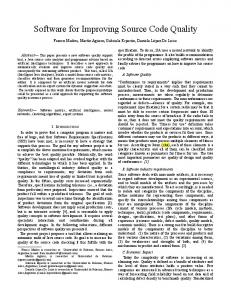
approach, which means that the instrumented code is inserted into a software application before compilation of source code. Instrumented code creates a record in the form of the user session trace. This record is attached to a software change request during the specification phase in the process. Later in the process, this session trace record is used as a basis for creating an initial impact set for the required change. This approach to code instrumentation is developed as suitable for business software applications that intensively use databases and in which user interface design reflects the underlying data structure [26][27]. This practically means that a request specified in the context of a visual form associated to an entity can influence visual forms and other related elements of software architecture that are associated to other entities that are in the relationship with the current one. Software architecture is designed to facilitate localization of a change in a set of software elements. This approach to application architecture design, with logical packages associated to each entity in database and visual interface that reflects database structure, enables automatic creation of an initial impact set. Due to the fact that the user interface reflects relationships in the database, created session trace record can be used for identification of visual forms related to the current one. The related visual forms are visual forms directly accessible from the current form. These related forms could be accessed in the following ways: • Selecting menu items from the main menu on the main application form, • Zooming related values on current visual form for working with one record of current entity, and • Through operations available in form toolbar on the forms that handle one entity or a set of entity records (table of records). The following abbreviations were introduced for code instrumentation depending on the place in a visual form source code where the instrumentation is implemented: • Code Instrumentation for Form Activation (CI_FA) is used for tracking form activation. It is implemented in form constructors. This means that there can be more than one place with instrumented code depending on the available ways for form activation. • Code Instrumentation for ZOoming activity (CI_ZO) is used with a zooming activity [26]. It is implemented in the code that handles an action associated to a zoom button. The exact place of the instrumented code is before the call of the other form constructor that implements the zooming activity. • Code Instrumentation for REturn (CI_RE) is used for tracking return to a form previously activated. In this case, the form will not be initialized. It is implemented in the segment of the form source code that deals with the operations that call (activate) other forms. The exact place of the instrumented code is after the call of the other form constructor. • Code Instrumentation for operations activated with Toolbar Buttons (CI_TB) is used in the case when the other form is activated through the
Form K CI_IS CI_MI CI_RE
Menu item
Return
CI_FA
CI_TB
CI_TB
Figure 2. Code instrumentation of visual forms
operation associated to the toolbar button. The common situation is when a user works on the form with the tabular representation of multiple records and needs to activate a form for managing a single record of the current entity. Typical operations are creation of a new record or change of an existing one. It is implemented in the segment of the form source code that deals with the operation associated to the selected toolbar button. The exact place of instrumented code is before the call of other form constructor. • Code Instrumentation for operations activated by Menu Items (CI_MI) is used in the case when a form is activated from the menu item on the main application form. It is implemented in the segment of the form source code that deals with the operation associated to a selected menu item. The exact place of instrumented code is before the call of the other form constructor. • Code Instrumentation for Initialization of user Session (CI_IS) is used in the case when a session of a new user is started (initialized). It is implemented in the segment of the main form source code that deals with the operation associated to the login activity. Fig. 2 presents a sample with all possible cases for using code instrumentation on the visual forms level. The sample includes also all possible ways of navigating between visual forms. Any type of listed code instrumentations can appear many times in a particular visual form, depending on the observed context. For example, if a task related to a complex entity requires zooming values in more than one associated entities, the code instrumentation for zooming (CI_ZO) will appear in an appropriate number of places within the code of the current visual form. Another example of the multiple occurrences of code instrumentation is related to the visual form activation (CI_FA). In that case, the code for instrumentation will be included in all constructors implemented in a visual form. The next obvious example is related to the activation of the visual forms by using menu items in the main application form. That means that the code for instrumentation of menu items' operations (CI_MI) will be attached to all operations associated to menu items that activate other forms. B. Initial Impact Set Model Initial impact set is a set of elements in a software product initially affected by a required change. This set is proposed or created before the impact analysis or in the
– 289 –
Z. Stojanov et al. • Using Code Instrumentation for Creating Initial Impact Set for Software Change Request
beginning of the impact analysis and can be changed during the process (see Fig. 1). Although the term starting impact set has been used in literature, in this approach the term initial impact set is adopted for the same purpose. The basic assumption for this approach is that elements of a software application can be presented as nodes in a graph that presents the architecture of a software application [28][12]. The basis of this approach is the introduction of the term current form that represents a visual form on which the user starts a process of specifying a change request. The current form is the node from which also starts the search of a graph of software elements with the goal to find all elements affected by the change (Actual Impact Set at Fig. 1). Change impact analysis goes in three directions regarding the starting node: previous forms included in the session trace, elements in the package associated to the current form (background components and associate database table), and visual forms directly accessible from the current one. Therefore, the following sets of elements that make software application are included in the initial impact set: • The set of previous forms, or visual forms that had been activated before a user activated the current form. These forms, and information about the way of their activation are recorded in the session trace. The session trace is created by using code instrumentation and later included in a software change request. • The set of elements in the package associated to the current visual form is identified from the model of the application. This set includes processing elements and storage elements that are directly associated to the current form (entity). • The set of next forms, or visual forms directly accessible from the current form. These forms are available through zooming operations, and can be identified from the data structure in database (parsing a database script). Initial impact set is modeled as an XML schema presented in Fig. 3. The process of forming the initial impact set consists of the following steps: • Extracting the current form from the application context in a change request and its inclusion in the initial impact set. current_form
•
Forming a set of previous visual forms and its inclusion in the initial impact set. • Forming a set of elements in the package associated to the current form, and its inclusion in the initial impact set. • Forming a set of next visual forms and its inclusion in the initial impact set. • Extracting the application name from the change request and its inclusion in the initial impact set. Since this paper deals only with using code instrumentation for creating an initial impact set as an initial data set for the impact analysis, other sets that are part of the impact analysis process (see article [21]) will not be described in details. IV.
REAL SETTING IMPLEMENTATION
Formal verification of the developed approach is realized in virtual network laboratory VNLab [29]. A software change request service that works in the context of a running application was integrated into software application ScenarioBuilder [30]. ScenarioBuilder is used for creating and managing network scenarios described in Network Node Description Language (NNDL) [31]. Network scenarios are stored in a database. Graphical user interface, developed with Java JFC/Swing library [32], reflects the database structure. Developed service uses code instrumentation to create a session trace and to attach it to a software change request. The most important part of a software change request for creation of the initial impact set is the application context that contains relevant data about the context in which the user starts change request specification. Data included in the application context are: information about the current form (the form name, launching time and launching way), software application name, user session start time, and the trace of all forms that were activated before the current form in the user session. Although only the current form name and the session trace will be included in the initial impact set, all other data can also be used in the impact analysis as a complement to a submitted software change request. On the VNLab portal server is deployed a service that receives software change request with the user session trace and creates the initial impact set. Software change request is received as an XML document. XML document is transformed into a set of objects using unmarshalling
{xs:string} next_forms {next_forms} package_elements initial_impact_set
S
{package_elements} previous_forms {previous_forms} application_name {xs:string} created {xs:date}
Figure 4. Sample initial impact set
Figure 3. Initial impact set XML schema
– 290 –
SISY 2012 • 2012 IEEE 10th Jubilee International Symposium on Intelligent Systems and Informatics • September 20-22, 2012, Subotica, Serbia
technique available in JAXB [33] technology. Elements of the initial impact set are created as objects and serialized into an XML document by using marshalling technique available in JAXB technology. Sample XML file with the initial impact set for the software change request created in the context of the visual form for handling firewall rule FormFirewallRule is presented in Fig. 4. V. CONCLUSIONS This paper presents an approach to instrument software application code in order to automate the process of change request specification and creation of the initial impact set. The approach is based on the following presumptions: software application architecture is organized in logical packages associated to entities in a database, and graphical user interface reflects the structure of database. Implementation in a real setting provides the evidence that this approach can be implemented in software applications that are based on databases and have graphical user interface. The main contribution of this research is a novel approach to creation of initial impact set as a support to change impact analysis. This is even more important if it is known that the change impact analysis is the most critical phase in software maintenance. The limitation of the presented research is the lack of empirical evidence based on the statistical analysis of the maintenance repository with software change requests and impact sets after longer period of usage. However, this constraint could be seen as a promising direction for further research. The findings of this research suggest the following research directions: development of methods that will assist in creating actual impact set, and implementation of the approach in commercial software application and analyzing change requests and impact sets for a period of few years.
[6] [7]
[8]
[9]
[10]
[11]
[12]
[13]
[14]
[15]
ACKNOWLEDGMENT
[16]
The Ministry of Education and Science, Republic of Serbia, supports this research under the project "The development of software tools for business process analysis and improvement", project number TR32044, 2011-2014.
[17]
REFERENCES [1] [2]
[3]
[4]
[5]
C. Jones. Software Engineering Best Practices. McGraw-Hill, Inc., New York, NY, USA, 2010. A. April and A. Abran. “A software maintenance maturity model (s3m): Measurement practices at maturity levels 3 and 4”. Electronic Notes in Theoretical Computer Science, 233:73–87, 2009. Proceedings of the International Workshop on Software Quality and Maintainability (SQM 2008). doi: 10.1016/j.entcs.2009.02.062. A. Abran, P. Bourque, R. Dupuis, J. W. Moore, and L. L. Tripp. Guide to the Software Engineering Body of Knowledge SWEBOK. IEEE Press, Piscataway, NJ, USA, 2004. G. A. Junio, M. N. Malta, H. de Almeida Mossri, H. T. MarquesNeto, and M. T. Valente. “On the benefits of planning and grouping software maintenance requests”. In 15th European Conference on Software Maintenance and Reengineering, pages 55–64, 2011. doi: 10.1109/CSMR.2011.10 P. Rovegard, L. Angelis, and C. Wohlin. “An empirical study on views of importance of change impact analysis issues”. IEEE Transactions on Software Engineering, 34(4):516–530, July 2008. doi: 10.1109/TSE.2008.32.
[18]
[19]
[20] [21]
[22]
– 291 –
D. C. C. Poo and M. K. Chung. “Case and software maintenance practices in Singapore”. Journal of Systems and Software, 44(2):97–105, 1998. doi: 10.1016/S0164-1212(98)10047-X. R. Arnold and S. Bohner. Software Change Impact Analysis. Wiley-IEEE Computer Society Press, Los Alamitos, CA, USA, 1 edition, 1996. R. S. Arnold and S. A. Bohner. “Impact analysis - towards a framework for comparison”. In Proceedings of the Conference on Software Maintenance, ICSM ’93, pages 292–301, Washington, DC, USA, 1993. IEEE Computer Society. doi: 10.1109/ICSM.1993.366933. B. Chan, K. Foo, L. Marks, and Y. Zou. “An approach for estimating the time needed to perform code changes in business applications”. International Journal on Software Tools for Technology Transfer (STTT), 11(6):503–515, 2009. doi: 10.1007/s10009-009-0122-5. A. v. Knethen and M. Grund. “Quatrace: A tool environment for (semi-) automatic impact analysis based on traces”. In Proceedings of the International Conference on Software Maintenance, ICSM ’03, pages 246–255, Washington, DC, USA, 2003. IEEE Computer Society. doi: 10.1109/ICSM.2003.1235427. M. Lindvall and K. Sandahl. “How well do experienced software developers predict software change?” Journal of Systems and Software, 43(1): 19–27, 1998. doi: 10.1016/S01641212(98)10019-5. Z. Stojanov. Improving change management methods through integration of a change request service in software product model. Phd dissertation, University of Novi Sad, Faculty of technical sciences, Novi Sad, Serbia, October 2011. [In Serbian]. M. Factor, A. Schuster, and K. Shagin. “Instrumentation of standard libraries in object-oriented languages: the twin class hierarchy approach”. SIGPLAN Notices, 39(10):288–300, October 2004. doi: 10.1145/1035292.1029000. N. Nethercote. Dynamic binary analysis and instrumentation. Technical Report UCAM-CL-TR-606, Computer Laboratory, University of Cambridge, Cambridge, UK, November 2004. C.-K. Luk, R. Cohn, R. Muth, H. Patil, A. Klauser, G. Lowney, S. Wallace, V. J. Reddi, and K. Hazelwood. “Pin: building customized program analysis tools with dynamic instrumentation”. In Proceedings of the 2005 ACM SIGPLAN conference on Programming language design and implementation, PLDI ’05, pages 190–200, New York, NY, USA, 2005. ACM. doi: 10.1145/1065010.1065034. C. Thiffault, M. Voss, S. T. Healey, and S. W. Kim. “Dynamic instrumentation of large-scale mpi and openmp applications”. In Proceedings of the 17th International Symposium on Parallel and Distributed Processing, IPDPS ’03, pages 65.2–, Washington, DC, USA, 2003. IEEE Computer Society. doi: 10.1109/IPDPS.2003.1213161. S. Yong and S. Horwitz. “Using static analysis to reduce dynamic analysis overhead”. Formal Methods in System Design, 27(3):313–334, 2005. doi: 10.1007/s10703-005-3401-0. G.-R. Uh, R. Cohn, B. Yadavalli, R. Peri, and R. Ayyagari. “Analyzing dynamic binary instrumentation overhead”. In Proceedings of the Workshop on Binary Instrumentation and Applications, San Jose, USA, October 2006. X. Gao, B. Simon, and A. Snavely. “Aliter: an asynchronous lightweight instrumentation tool for event recording”. ACM SIGARCH Computer Architecture News, 33(5):33–38, December 2005. doi: 10.1145/1127577.1127585. J. R. Larus. “Whole program paths”. SIGPLAN Notices, 34(5):259–269, May 1999. doi: 10.1145/301631.301678. S. A. Bohner. “Extending software change impact analysis into cots components”. In Proceedings of the 27th Annual NASA Goddard Software Engineering Workshop (SEW-27'02), SEW ’02, pages 175–182, Washington, DC, USA, 2002. IEEE Computer Society. doi: 10.1109/SEW.2002.1199468. G. Antoniol, G. Canfora, G. Casazza, and A. de Lucia. “Identifying the starting impact set of a maintenance request: A case study”. In Proceedings of the Conference on Software Maintenance and Reengineering, CSMR ’00, pages 227–230, Washington, DC, USA, 2000. IEEE Computer Society. doi: 10.1109/CSMR.2000.827331.
Z. Stojanov et al. • Using Code Instrumentation for Creating Initial Impact Set for Software Change Request
[23] Z. Stojanov. “Using change request generator for change request specification at customer side”. In Proceedings of the 3rd Balkan Conference in Informatics, volume II, BCI 2007, pages 237–248, Sofia, Bulgaria, 27-29 September 2007. [24] Z. Stojanov, B. Perisic, and D. Dobrilovic. “Extension of software architecture model with the services for handling change requests”. In Proceedings of the 54th ETRAN conference, RT4.31-4, Donji Milanovac, Serbia, 7-11 June 2010. [25] Z. Stojanov, D. Dobrilovic, and B. Perisic. “Modeling a submission phase of change request process in context of a running application”. In Proceedings of the 7th IEEE International Symposium on Intelligent Systems and Informatics, SISY 2009, pages 131–136, Subotica, Serbia, 25-26 September 2009. doi: 10.1109/SISY.2009.5291178. [26] G. Milosavljevic and B. Perisic. “A method and a tool for rapid prototyping of large-scale business information systems”. Computer Science and Information Systems, 1(2):57–82, 2004. [27] B. Perisic, G. Milosavljevic, I. Dejanovic, and B. Milosavljevic. “UML profile for specifying user interfaces of business applications”. Computer Science and Information Systems, 8(2):405–426, 2011. doi: 10.2298/CSIS110112010P.
[28] D. Le Metayer. “Software architecture styles as graph grammars”. ACM SIGSOFT Software Engineering Notes, 21(6):15–23, October 1996. doi: 10.1145/250707.239105. [29] D. Dobrilovic, V. Brtka, I. Berkovic, and B. Odadzic. “Evaluation of the virtual network laboratory exercises using a method based on the rough set theory”. Computer Applications in Engineering Education, 20(1):29–37, 2012. doi: 10.1002/cae.20370. [30] Z. Stojanov, D. Dobrilovic, and B. Perisic. “Integrating software change request services into virtual laboratory environment: Empirical evaluation”. Computer Applications in Engineering Education, 2011. DOI: 10.1002/cae.20529. [31] D. Dobrilovic, Z. Stojanov, B. Odadzic, and B. Markoski. “Using network node description language for modeling networking scenarios”. Advances in Engineering Software, 43(1):53–64, 2012. doi: 10.1016/j.advengsoft.2011.08.004. [32] K. Walrath, M. Campione, A. Huml, and S. Zakhour. The JFC Swing Tutorial: A Guide to Constructing GUIs, Second Edition. Addison Wesley Longman Publishing Co., Inc., Redwood City, CA, USA, second edition, 2004. [33] S. Vajjhala and J. Fialli, editors. JSR-000222, Java Architecture for XML Binding (JAXB) 2.0. Sun Microsystems, Inc., Santa Clara, USA, April 2006. http://www.jcp.org/en/jsr/detail?id=222.
– 292 –