Using Formal Description Technique ESTELLE for Manufacturing Systems Specification or Description
Sousa, R. a; Putnik, G. b; Moreira, F. c Production and Systems Engineering Department - School of Engineering University of Minho, Campus of Azurém, 4800 Guimarães, Portugal Tel: ++351 (0)53 510278, Fax: ++351 (0)53 510268 a b c Email:
[email protected] Email:
[email protected] Email:
[email protected]
ABSTRACT Usually the description of a system is given in natural language or in diagrams. It is very hard to make this kind of informal description clear, concise and unambiguous. Implementations based on informal specifications are usually prone to errors, omissions and incompatibilities. This paper presents an attempt to introduce Formal Description Techniques (FDT's), originally developed for the area of telecommunications and data transfer, as a mean for the specification/description of manufacturing systems. A brief introduction on standard FDT's, LOTOS, ESTELLE and SDL is given. Several concepts were behind the development of these techniques and this paper exploits the extended finite state machine (EFSM) concept as a suitable form for specification/description of manufacturing systems using FDT ESTELLE.
KEYWORDS Formal Description Techniques; Formal Specification; ESTELLE; Manufacturing Systems.
1. INTRODUCTION In the decade of 70 CCITT1 (International Consultative Committee on Telegraphy and Telephony) and ISO (International Organisation for Standardisation) started to work on Formal Description Techniques (FDT's). The main motivation arises from the fact that: "…only formal approaches to system specification, verification, analysis, implementation, testing and operation could provide the means to control the ever-growing complexity of standards for telecommunications and OSI (Open Systems Interconnection)." [Turner 93]. From that work resulted three standard FDT's: ESTELLE (Extended Finite State Machine Language) [ISO 89e]; LOTOS (Language of Temporal Ordering Specification) [ISO 89l] and SDL (Specification and Description Language) [CCITT 88]. Although especially developed for the field of telecommunications there is nowadays an increasing interest in the use of FDT's in other areas like robotics, security, finance, production systems, etc. In this paper we intend to introduce FDT ESTELLE as a potential technique for specification or description of manufacturing systems. The paper is organised as follows. Section 2 gives a brief introduction on LOTOS, ESTELLE, and SDL Formal Description Techniques, presenting the concepts behind each one of them. Section 3 presents ESTELLE formal description technique showing some of its constructs and capabilities especially those that are particularly important for our subject. In section 4 we can find the mapping of an informal diagram of a manufacturing system example into a formal Estelle architecture. Two different implementations of that architecture are presented and part of the formal description in ESTELLE is given. 1
Now ITU-T (International Telecommunications Union - Telecommunication Standardisation)
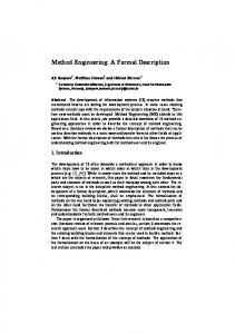
2. FORMAL DESCRIPTION TECHNIQUES IN GENERAL Several decades of work on formal specification languages and rigorous methods, for computer system development, provided the foundations to the birth of Formal Description Techniques (FDTs). The ISO FDT group recognised that two categories of approaches could be used on the FDTs development process; finite state automata and algebraic ideas. Within the first category was standardised the FDT ESTELLE (Extended Finite State Machine Language) in 1989. LOTOS (Language of Temporal Ordering Specification) was standardised also in 1989 and is based on the second category approaches. SDL (Specification and Description Language) results from CCITT work on specification of telecommunications systems. SDL was first (1976) an informal diagrammatic design notation but after several years of evolution (in cooperation with ISO) has become a complete FDT (1988). LOTOS provides means to deal with two different aspects; system behaviour and Abstract Data Types (ADT). System behaviour is modelled using process algebras: CCS (Calculus of Communicating Systems) [Milner 89] and CSP (Communicating Sequential Process) [Hoare 85]. Abstract data typing is based on ACT ONE [Ehrig and Mahr 85], an abstract data type language.ESTELLE is based on an extension of the traditional finite state model. This extension was introduced in order to deal, among other things, with one of the problems of real systems - state-space explosion. Specifications are written in a variation of PASCAL standard and probably that is why ESTELLE is considered the easiest of the FDTs (concerning the learning process). SDL provides two kinds of representation: GR (Graphical Representation) and PR (Phrase Representation). The GR form is straightforward and it is always possible to do the automatic translation between GR and PR. Like ESTELLE, SDL describes a system as a set of communicating extended finite state machines, and like LOTOS includes abstract data typing capabilities. SDL is the FDT with more commercial tools available, from graphical editors to code generators. 3. ESTELLE ESTELLE is particularly adequate to describe distributed or concurrent systems and models a system as a hierarchically-structured set of modules communicating through channels with bi-directional capability, attaching2 its interaction points (fig. 1). Module D
C
Channel
Parent I
Child
ModuleName
B
A
Interaction Point
Submodule
Figure 1: Estelle architecture elements An ESTELLE automaton (extended finite state machine) describes the behaviour of each module. A module (parent) can be structured into sub-modules (child) which also can have its own children. Two modules communicate through a channel exchanging messages (interactions). The declaration of a channel requires the definition of the channel name, two formal parameters identifying each one of the communicating modules and the interactions (messages) allowed in each direction. Consider the example given in figure 2.
Control
C
M
MachineTool
Figure 2: Simple architecture example 2
Attach and connect have different meanings in ESTELLE
The channel between interaction points C and M could be declared in ESTELLE as follows: channel CommunicationServer(Controller, Equipment); by Controller: {*** Interactions produced by Controller ***} StartProgram; StopProgram; by Equipment: {*** Interactions produced by Equipment ***} Operating; Stopped;
Controller and Equipment are formal parameters that will be substituted by actual module names when the channel is instantiated. Interactions StartProgram and StopProgram are allowed in channel CommunicationServer if initiated by the module that plays the role of Controller (Control in the case of fig. 2). Similarly interactions Operating and Stopped are only allowed in this channel if originated by the module that plays the role of Equipment (MachineTool in this case). None of these interactions carry parameters but if necessary that is possible. For example the interaction StartProgram could carry a parameter ProgramNumber used by the machine to select the program to be executed. … by Controller: StartProgram(ProgramNumber: integer); …
Associated to each module there is a queue where are placed the received interactions. Each interaction point can have its own queue or a common queue could be defined. In that case the interactions received by all of the module's interaction points are stored in the common queue. Specification of a module requires a header definition and a body definition. More than one body could be declared to use with the same header. When instantiating the module one of the bodies is chosen. Several instances of the same module can occur and each one with different or equal bodies. Header definition includes the module's class (process or activity), a list of interaction points with involved channels and, if used, a list of exported variables. Header for the MachineTool module in figure 2 is: module MachineTool systemprocess; ip M: CommunicationServer(Equipment) individual queue; end; {MachineTool header}
In this simple case module MachineTool has only one interaction point, M, associated with channel CommunicationServer where module MachineTool plays the role of Equipment. An individual queue for interaction point M has been declared. It is possible to omit the queue discipline declaration in the module header if a default declaration is placed at the beginning of the specification. The body specifies the module's behaviour using the state machine concept. Assuming a very simplified operation mode of the machine tool, the state diagram on figure 3 could be used to describe module MachineTool. M.StartProgram/ M.Operating M.StopProgram/
M.StartProgram/
STOPPED
RUNNING
M.StopProgram/ M.Stopped
Figure 3: State diagram for MachineTool module
The body for MachineTool module could be, accordingly with figure 3: body MachineToolBody for MachineTool state STOPPED, RUNNING; initialize to STOPPED begin end; trans when M.StartProgram from STOPPED to RUNNING begin output M.Operating; … end; from RUNNING to same begin end; when M.StopProgram from RUNNING to STOPPED begin output M.Stopped; … end; from STOPPED to same begin end; end; {MachineToolBody}
{*** States required ***} {*** Initial state ***}
{*** Interaction StartProgram received through interaction point M ***}
{*** Interaction Operating send through interaction point M ***}
{*** If running ignore StartProgram interaction ***}
{*** Interaction StopProgram received through interaction point M ***}
{*** Interaction Stopped send through interaction point M ***}
{*** If stopped ignore StopProgram interaction ***}
The keywords when and from are clauses used by the guard of a transition. A transition can only be fired if all the clauses of its guard are satisfied. Other clauses are available in ESTELLE: to, provided, priority, any and delay. A complete explanation can be found in [ISO 89] or [Turner 93]. A conventional transition requires some input (interaction arriving through an interaction point) defined in clause when of its guard. ESTELLE allows transitions that do not require input - spontaneous transitions. Usually time constraints are associated to spontaneous transitions (using clause delay) to retard their firing. The above description of MachineToolBody is written in the "event driven" style where the clause when is used in first place. This style is used when we want to emphasise the behaviour of the module in terms of incoming events (interactions). If the idea is to emphasise the actions of the automaton in a given state then it is possible to rewrite the description in the "state driven" style (clause from used first): … from STOPPED when M.StartProgram to RUNNING begin output M.Operating; … end; when M.StopProgram to same begin end; …
{*** From the STOPPED state ***} {*** If interaction StartProgram received ***} {*** state change to RUNNING ***} {*** Interaction Stopped send through interaction point M ***}
{*** If stopped ignore StopProgram interaction ***}
The meaning of the description does not change when different styles are used3. The extended finite state machine use context variables (not used in the above examples) in association with a regular finite state machine, in order to deal with the problem of state-space explosion. The state of this "regular automaton" is designated control state or major state and in conjunction with context variables defines the total state of the module. The module chooses an action to perform based on the total state, input interactions and priority associated with transitions. ESTELLE includes non-determinism - in a particular instant of time more than one action could be available to execution, but only one of them could be performed. 3
In software engineering area, automatic code generation from ESTELLE specifications is affected by semantic constraints, with implications in the performance of the implementation [Henke and Thiel 97].
4. MANUFACTURING SYSTEM EXAMPLE In order to exemplify the construction of ESTELLE architecture diagrams consider the manufacturing system informally represented on figure 4.
Local Controller
WAN
Remote Controller
LAN
Cell Controller
Cell Controller
Cell Controller
Machine
Machine
Transporter
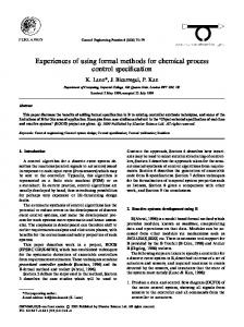
Figure 4: Informal representation of a manufacturing system example This diagram can conduce to different implementations. Two of them are presented on figure 5 and figure 6.
Figure 5: Layout installation (figure from [Considine 86]). In figure 5 each machining center includes the blocks cell controller (CNC) and machine, of figure 4. The particular implementation of figure 6 is associated to a project of the Production and Systems Engineering Department-University of Minho. This project concerns Virtual/Distributed Manufacturing Systems (D/V MS Project), detailed in [Putnik 98]. ESTELLE architecture for this installation is presented on figure 7.
Video camera
D/V MS Project Robot Controller
Conveyor M achine 2
I/O
cha nn el
M achine 1
PLC I/O channel
I/O channel
Local Area Network
Internet
Remote Controller
Local Controller
Figure 6: Experimental Distributed/Virtual Manufacturing System (D/V MS)- Layout. MachineCell
RobotCell
M
R
M
R LAN
C C LocalController
RemoteController
LC
RC
ML
MR WAN
Figure 7: Experimental Distributed/Virtual Manufacturing System (D/V MS) - ESTELLE architecture The ESTELLE specification requires the description of all the modules and channels of the architecture. The complete description of this system would be very large, so only a small part, concerning module MachineCell, is presented here. The architecture of MachineCell module is on figure 8. MachineCell
Sensors
Actuators
O
I
S
A Controller
T
T
Timer
C M
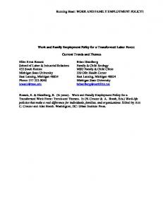
Figure 8: D/V MS MachineCell module - architecture In this experimental installation the machine is a very simple device that receives parts (feed by the robot) and commands from the local controller. It has a sensor that indicates the presence of a part and an emergency
button to stop the machine. There is only one actuator - a pneumatic cylinder controlled by an electric valve that removes the part when the "operation" is complete. There is no physical operation, only a delay to simulate operation time. Each machine can process several kinds of parts. The machine sensor only detects the presence, not the kind of the part. So the local controller must implement a mechanism to control the buffer composition in each machine. This is possible because the local controller has information given by the vision system from the robot cell, indicating which kind of part is being manipulated. The automaton on figure 9 describes the operation of the Controller module. The character (followed by the dot) before the name of each interaction identifies the interaction point through which the interaction occurs.
S.Stop/C.MachineStopped
FREE
S.PartPresent/ C.PartWaiting
T.TimeOut/ A.RemovePart, C.OperationConcluded
C.Reset/A.RemovePart
WAITING COMMAND
S.Stop/ C.MachineStopped
STOPPED
C.StartOperation(OpTime)/ T.StartTimer(OpTime), C.MachineOperating
S.Stop/ C.MachineStopped
OPERATING S.Stop/C.MachineStopped
Figure 9: Finite State Machine for Controller module Accordingly to the kind of the part the local controller sends to the machine controller a command to start the operation that includes the operation time (interaction with a parameter - StartOperation(OpTime: integer)). This operation time is used by the Timer module to control the operation. Four channels are associated to the Controller module (and MachineCell module). channel SensorsServer(Medium, Control); by Medium: PartPresent; Stop; channel ActuatorsServer(Control, Medium); by Control: RemovePart; channel TimerServer(Timer, Control); by Control: StartTimer(OpTime: integer); by Timer: TimeOut; channel MachineServer(Machine, LocalControl); by Machine: PartWaiting; MachineOperating; OperationConcluded; MachineStopped; by LocalControl: StartOperation(OpTime: integer); Reset;
{*** Interactions produced by sensors ***}
{*** Interactions produced by machine controller ***}
{*** Interactions produced by machine controller ***} {*** Interactions produced by Timer ***}
{*** Interactions produced by machine cell ***}
{*** Interactions produced by local controller ***}
The channels SensorsServer and ActuatorsServer are unidirectional. All interactions, except StartOperation and StartTimer, do not carry parameters.
The header for Controller module is: module Controller systemprocess; ip S: SensorsServer(Control) individual queue; A: ActuatorsServer(Control) individual queue; T: TimerServer(Control) individual queue; C: MachineServer(Machine) individual queue; end; {Controller header}
{*** interaction points ***}
Accordingly with the automaton on figure 9 the part of the body for the Controller module could be: body ControllerBody for Controller; state FREE, WAITING_COMMAND, OPERATING, STOPPED; initialize to FREE begin end;
{*** States required ***} {*** Initial state ***}
trans from FREE {*** From the FREE state ***} when S.PartPresent {*** If interaction PartPresent received ***} to WAIT_COMMAND {*** State change to WAITING_COMMAND ***} begin output C.PartWaiting; {*** Interaction PartWaiting send through int. point C ***} end; when S.Stop {*** If interaction Stop received ***} to STOPPED {*** State change to STOPPED ***} begin output C.MachineStopped; {*** Interaction MachineStopped send through int. point C ***} end; when C.StartOperation {*** Ignore StartOperation interaction ***} to same begin end; when C.Reset {*** Ignore Reset interaction ***} to same begin end; when T.TimeOut {*** Ignore TimeOut interaction ***} to same begin end; from WAITING_COMMAND {*** From the WAITING_COMMAND state ***} when C.StartOperation {*** If interaction StartOperation received ***} to OPERATING {*** State change to OPERATING ***} var OperatingTime: integer; {*** Local variable ***} begin OperatingTime:=OpTime; {*** Parameter carried by interaction StartOperation ***} output T.StartTimer(OperatingTime); {*** To simulate operation time ***} output C.MachineOperating; {*** Information to local controller ***} end; when S.Stop {*** If interaction Stop received ***} to STOPPED {*** State change to STOPPED ***} begin output C.MachineStopped; {*** Information to local controller ***} end; … end; {ControllerBody}
Obviously the complete description of the module's body would be inadequate here. The intention is to illustrate the technique, in this case in the "state-driven" style. Note that the formal specification defines the behaviour of the finite state machine in each state to all the input interactions, which do not happens on the finite
state diagram. For example observing the state diagram (figure 9) it is not explicit what happens if a StartOperation interaction arrives while the automata is in state FREE. The formal specification states that in this situation the automata accept the interaction but just ignore it. The structure of the entire specification will be: specification DVMSProject; {*** Data typing ***} {*** Channel definition ***} {*** Module definition (header and body) ***} modvar MachineCellInstance: MachineCell; RobotCellInstance: RobotCell; LANInstance: LAN; LocalControllerInstance: LocalController; … initialize begin init MachineCellInstance with MachineCellBody; init RobotCellInstance with RobotCellBody; init LANInstance with LANBody; init LocalControllerInstance with LocalControllerBody; … connect MachineCellInstance.M to LANInstance.M; connect RobotCellInstance.R to LANInstance.R; connect LANInstance.C to LocalControllerInstance.C; … end; end. {DVMSProject}
Within MachineCellBody definition is the definition of Controller sub-module (header and body) presented previously and, obviously, all other sub-modules of MachineCell module (fig. 8). 5. CONCLUDING REMARKS In this paper is investigated the adequacy of the Extended Finite State Machine concept and FDT ESTELLE, to the formal description/specification of manufacturing systems. This work should be seen as an attempt to use FDT's in other area than the original one (telecommunications) and it was indeed shown that ESTELLE could be used to describe at least some kind of manufacturing systems. It is obvious that a complete ESTELLE description/specification is very large, but this also happens with the other Formal Description Techniques LOTOS and SDL. The main benefits of formal approaches are the unambiguous, clear, concise and complete specifications. The graphical representation (GR) included in SDL is very straightforward, and that is why a next version of LOTOS and ESTELLE will probably include graphical syntax too. It is accepted that ESTELLE is the easiest FDT to learn, so it is a good way to enter in the area of formal specifications. In an Estelle specification the complete enumeration of the events in each state (see Controller module definition) could be a tedious task, and that is one of the points where tool-sets could help. Each FDT has its own characteristics and accordingly to our case we must choose the most adequate one. However it is important to understand that the formal specification of a complex system, is complex by nature. FDT is a not wonder-tool that simplifies complexity.
REFERENCES [CCITT 88]
CCITT Z.100: “Specification and Description Language”, International Consultative Committee on Telegraphy and Telephony, Geneva.
[Considine 86]
Considine M. D. (ed.): "Standard Handbook of Industrial Automation", Chapman and Hall 1986
[Ehrig and Mahr 85]
Ehrig, H. and Mahr, B.: "Fundamentals of Algebraic Specification", 1 EATCS Monographs on Theoretical Computer Science, 6, Springer-Verlag, Berlin
[Henke and Thiel 97]
Henke, R.; Mitschele-Thiel, A.; Konig, H.: "On the Influence of Semantic Constraints on the Code Generation from Estelle Specifications", Proceedings of FORTE X/PSTV XVII '97 - Formal Description Techniques and Protocol Specification Testing and Verification, Chapman & Hall
[Hoare 85]
Hoare, C. A. R.: "Communicating Sequential Processes", Prentice-Hall International, Englewood Cliffs, New Jersey
[ISO 89e]
ISO/IEC 9074: “Information Processing Systems - Open Systems Interconnection ESTELLE - A Formal Description Technique based on an Extended State Transition Model", International Organisation for Standardisation, Geneva
[ISO 89l]
ISO/IEC 8807: “Information Processing Systems - Open Systems Interconnection LOTOS - A Formal Description Technique based on the Temporal Ordering of Observational Behaviour”, International Organisation for Standardisation, Geneva
[Milner 89]
Millner, A. J. R. G.: "Communication and Concurrency", Addison-Wesley Reading, Massachusetts.
[Putnik 98]
Putnik, G.D.; Sousa, R.M.; Moreira, J.F.; Carvalho, J.D.; Spasic, Z., Babic, B.; “Distributed/Virtual Manufacturing Cell: An Experimental Installation”, 4th International Seminar on Intelligent Manufacturing Systems, Belgrade, 1998. (Accepted to be published).
[Turner 93]
Turner, Kenneth J. (ed.): “Using Formal Description Techniques - An Introduction to ESTELLE, LOTOS and SDL”, John Wiley & Sons.