number of frequency channels, our system has less channel contention, lower packet latency, higher packet delivery ratio and lower energy consumption.
Using Frequency Division to Reduce MAI in DS-CDMA Wireless Sensor Networks Bao Hua Liu, Chun Tung Chou, Justin Lipman, Sanjay Jha School of Computer Science and Engineering, The University of New South Wales Email: {mliu, ctchou, justinl, sjha}@cse.unsw.edu.au
Abstract— The performance of Direct Sequence Code Division Multiple Access (DS-CDMA) sensor networks is limited by Multiple Access Interference (MAI). This paper proposes using frequency division to reduce the MAI in a DS-CDMA sensor network. We provide theoretical characterization of the mean MAI at a given node and show that a small number of frequency channels can reduce the MAI significantly. In addition, we provide a comparison of our proposed system to systems which do not use frequency division or which employ contention based protocols. Our study found that, by using only a small number of frequency channels, our system has less channel contention, lower packet latency, higher packet delivery ratio and lower energy consumption.
I. I NTRODUCTION We consider a wireless sensor network that consists of numerous sensor/actuator devices with integrated sensing, embedded microprocessors, low-power communication radios, on-board energy, with location awareness and organized in an ad hoc multi-hop network. Since sensor network applications are expected to utilize low data rate (e.g., 1-100Kbps), have small data packet size (e.g., 50 bytes), and sensors normally have limited energy, buffer space, and other resources, the contention based protocols may not be a suitable choice. Contention based protocols suffer from both low network throughput and long packet delays. Associating with each small data packet transmission, the RTS/CTS control packet exchange produces significant overheads. Woo and Culler [6] state that an RTS-CTS-DATA-ACK handshake sequence in transmitting a packet can constitute up to 40% overhead with small packet size in sensor networks. Although IEEE 802.11 standard specifies that RTS/CTS can be avoided with small data packet transmission, this may not be a suitable choice for sensor networks. Given the low data rate (e.g., 20Kbps) in sensor networks, a small data packet will take longer time to transmit than in an IEEE 802.11 network which has higher data rate (e.g., 2Mbps). As a result, the collision probability in sensor networks is much higher. Moreover, some energy efficient algorithms proposed for contention based protocols for sensor network require the information embedded in RTS/CTS packets. For example, SMAC [7] uses the transmission time embedded in RTS/CTS to turn off unintended receivers to avoid the energy consumption caused by overhearing. Furthermore, contention based protocols also suffer from the well documented hidden node and exposed node problems. It is well known that energy consumption is the crucial factor in sensor network design. This may lead to sensor network MAC protocols which prioritize energy savings over network throughput and packet latency. However, we argue that both network throughput and packet latency are critical for many sensor network applications, such as battlefield surveillance, real-time monitoring seismic waves, machine operations, bush fires, etc. Accurate and timely delivery of
sensed data in these cases sometimes means the difference between life and death. In this paper, we propose a frequency division based DS-CDMA system which can simultaneously achieve high energy efficiency, high network throughput and low packet latency. These advantages are a result of applying frequency division to reduce the MAI in the system. By using an analytical model, we show that a small number of frequency channels can reduce MAI significantly. This paper makes the following contributions: - Propose to use frequency division to reduce MAI in a wireless sensor network environment. - A mathematical model to calculate the expected value of MAI at a given node in a uniformly distributed sensor node topology. - Through discrete event simulation (using NS-2), we show that the proposed system can achieve less channel contention, lower packet latency, higher packet delivery ratio, and lower energy consumption. Organization — The rest of this paper is organized as follows. Section II provides preliminary knowledge and the problems of using DS-CDMA system in sensor networks. Section III describes the proposed design architecture, analytical model and several important issues. Section IV provides simulation results and analysis. Section V describes related work. We conclude our paper in section VI with future research directions. II. T HE L IMITATIONS OF DS-CDMA S YSTEM DS-CDMA system uses Spread Spectrum (SS) modulation technique, in which the baseband signal is spread using a Pseudo Noise (PN) code. The multi-user, multiple access interference (MAI) environment of DS-CDMA introduces significant challenges on how interference can be properly controlled. Consider a DSSS/BPSK (Direct Sequence Spread Spectrum/Binary Phase Shift Keying) system, let P0 denote the average received power of the desired signal. Assume that there are k interferers with received powers P1 , P2 , . . . , Pk , then the effective bit energy-to-noise ratio at the detector is given by [12]: !−1 Ã P k 2 i=1 Pi Eb 1 µ, + (1) = N0eff 3LP0 µ0 where L is the processing gain, and µ0 = Eb /N0 equals Eb /N0eff at the detector in the absence of interferers. The probability of bit √ error Pe with a given µ is then given by Pe = 12 erfc( µ) which is decreasing function of µ. In a cellular DS-CDMA network, the MAI can be controlled by the base station by limiting the number of active nodes and requiring that all active nodes control their transmission power so that the received power at base station is the same. However, the same principle can not be applied to a practical sensor network.
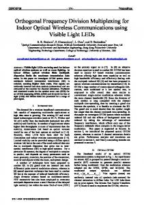
The difficulty of using DS-CDMA system in a sensor network lies in the fact that a sensor network does not have a centralized base station which leads to the MAI being uncontrollable. Consider the situation in Figure 1, where sensors are randomly deployed and RR represents the communication range. Each node has a number F
H I
E
J
C
D
A
B
RR
RR G
K
Fig. 1.
Example showing DS-CDMA MAI and near-far problem.
of neighbors situated at different distances. For example, A has neighbors B, E, F, D, and G, with each having different distance to A. Assume that each node uses the minimum required power to communicate with each other. When A is transmitting to a neighbor, the interference power caused by this transmission at other neighbors can have different values. Considering two simultaneous transmissions from A → B and C → D, where distance dAB À dAD , the interference power at D caused by the closer neighbor A is much higher than that of the desired power from C, and this makes the desired signal hard to be recovered. However, if the transmission is A → E instead of A → B, the interference caused to D’s reception is negligible. The problem caused due to interference signal(s) drowning out desired signal at a receiver is a consequence of MAI. This example demonstrates that it is not possible to use power control to minimize the effect of MAI in a DS-CDMA sensor network. The MAI may cause significant degradation in network throughput and is considered the main problem prohibiting the usage of DS-CDMA in sensor networks.
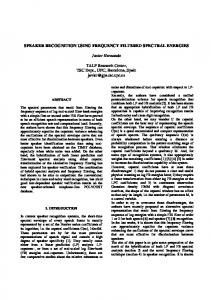
PN codes. - Sensors can adjust their transmission power to reach different neighbors. A. System Architecture and Channel Allocation Pattern A set up phase is required for our sensor network architecture where, during this phase, frequency channels and PN codes are assigned to enable the nodes to communicate during steady state. This set up phase has been discussed in our earlier paper [16]. In this paper, we focus on the steady state operation which we will describe now. In our protocol design, each node is assigned a unique receiving frequency different to its neighbors. Each directed link is also assigned a unique PN code that is different from its adjacent links. Two directed links are adjacent if they have a common end node. Both frequency channels and PN codes can be re-used spatially. Orthogonalization in frequency also implies that reception and transmission can happen concurrently. When a node wants to transmit a packet to a neighbor, it synthesizes its transmitter to the corresponding receiving frequency of the neighbor and uses the predetermined PN code with the neighbor to spread the baseband signal. Without loss of generality, we use a regular graph shown in Figure 2 to explain the concept. The receiving frequency of each B f7 G
PN2
C
PN3
A
f1
PN1
f6
PN4
PN5
f3 F
f5
D
f4 E
III. T HE P ROPOSED D ESIGN In the last section, we discussed the limitations of using DSCDMA system in sensor networks. The root cause of MAI lies in the fact that, unlike FDMA and TDMA channels, CDMA codes are not completely orthogonal. Completely orthogonal codes (e.g., Walsh codes) are normally used in synchronous systems. However, in asynchronous systems, perfect orthogonal codes are sub-optimal and exhibit high cross-correlation. Because MAI is caused by the non-perfect orthogonality of CDMA codes, the rationale of our design is to orthogonalize the reception in the vicinity of a sensor node. In this paper, we propose to use frequency division to reduce the MAI. As most sensor network applications normally operate with low data rate, it is possible to use a narrow band CDMA system operating over multiple frequency channels. Let’s assume that the data rate of the application is 20 Kbps, and we use 50 chip/bit PN code to spread the baseband signal. The resulting bandwidth is 1MHz. With 2.4GHz ISM band (2400MHz-2483.5MHz), we can have more than 80 frequency channels. We make the following assumptions in our design: - Sensors are normally static nodes. - A topology control protocol is available to limit the number of neighbors. - Multiuser detection receivers are available but may only be monitoring a limited number (e.g., number of neighbors) of
f2
Fig. 2.
System architecture and channel allocation pattern.
node is shown next to the node. The PN code used for each directed link is shown along the link. When A wants to transmit to D, it synthesizes its transmitter to f 5 and uses P N 4 to spread the data packet. Note this transmission does not cause interference to other neighbors such as C, B, G, F, E because their receivers are running on different receiving frequencies. Also note that B, F and D can transmit to A simultaneously because A’s multiuser detection receiver can distinguish all its neighbors’ transmissions concurrently. Note that A does not need to monitor the whole set of PN codes but only the set of codes that are employed by its immediate neighbors. A’s transmission to D will not destroy A’s reception from B, F and D even if they are happening in parallel because they are operating on different frequencies. Furthermore, the transmission signal from G to B will not contribute to the noise floor at A because it is operating on f 7. To this end, we notice that MAI only occurs at a given receiving node (e.g., A) when multiple neighbors (e.g., B, F, D) transmit to this node (e.g., A) simultaneously. When these simultaneous transmissions occur, they are actually desired signals as they are all addressed to this node (e.g., A). With proper power control, the resulted MAI at this node (e.g., A) can be controlled at the lowest level. Those uncontrollable
MAI presented in a pure DS-CDMA system, which is caused by the transmission between an interference node (e.g., G) and its neighbor (e.g., B but not A), is actually removed due to the frequency division. Note it is possible that some other nodes are transmitting with the same frequency in the network (as frequencies are reused spatially). But assuming that the channel allocation scheme (see next) can be met, these transmissions are normally far enough and the resulted interference are negligible. Because a node does not have to consider the interference caused by its transmission on the unintended receivers, it is much easier for a node to control its transmission power to guarantee that the transmitted signal arrives at the intended receiver with a certain power level, e.g., the lowest receiving threshold. We represent a sensor network by a graph G = (V, E), where V is the set of nodes, and E is the set of logical links. We assume only bilateral links exist. A logical link (a, b) means that node a considers node b as a neighbor if and only if node b also considers node a as a neighbor. Figure 2 also shows the channel allocation pattern. The frequency channel allocation is a two-hop vertex coloring problem in graph theory: where nodes sharing a common neighbor can not have the same color. The minimum number of required frequencies (colors) k can be given from Brook and Vizing theorem [14]: k = min{∆(∆ − 1) + 1, |V |}
(2)
where ∆ represents the node degree of the graph G. There are several schemes for the PN code assignment: receiverbased, transmitter-based, or pairwise code assignment [10]. Since frequency channel assignment is receiver-based, PN code assignment should use either transmitter-based, where all neighbors of a given node have different codes for transmitting; or transmitter-receiver pair based, where no two adjacent directed links in the logical topology have the same code. Both schemes can be used. The transmitter based code assignment is also a two-hop coloring problem. We adopted the pairwise code assignment scheme (as shown in Figure 2) in our current design because it requires a smaller number of codes than the transmitter-based scheme. By employing frequency division, our protocol design can achieve significant reduction in MAI and consequently less contention. This makes it possible to remove control packet (RTS/CTS) exchange which leads to higher packet delivery ratio, lower packet latency, and less energy consumption. frequency division also decreases the energy consumption due to reduction of overhearing. B. Multiple Access Interference Modeling In this section, we provide the analytical model for the mean MAI at a given node, and how the number of frequency channels can influence the mean MAI. Following assumptions are used in this analysis: - Sensor nodes are randomly uniformly distributed. - Each node transmits with an independent probability to a random neighbor. - We assume a random frequency allocation pattern which represents the worst case comparing with the systematic frequency allocation pattern discussed in section III-A. We assume that the node whose mean MAI we are interested to compute is located at the origin with receiving frequency f0 . We assume a sensor network with h nodes which are randomly and uniformly deployed into a plane R ⊆ R2 . For convenience, we assume R to be a square [0, d]2 , having area kRk = d2 , and suppose
d and h increase together in such a manner that h/kRk → λ where 0 < λ < ∞. Let S denotes a bounded Borel subset of R. For large d where kRk À kSk, and then the chance that S contains precisely k of the uniformly distributed nodes is given by [15]: P [k in S] =
¶k µ ¶h−k µ ¶µ kSk n kSk 1− kRk kRk k
(3)
As R increases, the binomial distribution of equation 3 is well approximated by a Poisson process: P [k in S] =
(λkSk)k −λkSk e k!
(4)
where λ equals the mean number of nodes per unit area of R, or node density. We first analyze the distribution of the interference power at the origin which is caused by an interference node. Assume that each node has a bounded normalized (The normalization is with respect to antenna gain, system loss, and wavelength) maximum transmission power PT . Let PR denote the lowest receiving threshold, then by using the propagation p law, the maximum transmission range RR is given by RR = n PT /PR , where n is the path loss exponent1 and normally 2 < n < 6. Let PI be carrier p sense threshold, then the interference range RI is given by RI = n PT /PI . We assume that each node has perfect power control so that the power level of the desired signal at the intended receiver equals to PR . Now consider that an interference node i is transmitting to a random neighbor node j as shown in Figure 3. The transmission y j i
d ij
di O
x
RR
RI
Fig. 3.
Interference model.
power of node i is a random variable that is dependent on the distance between node i and node j. We define this random variable as xij , where xij = PR dn ij
dij ∈ (0, RR ]
(5)
Note dij is also a random variable representing the inter-nodal distance. Assume that both the node at the origin O and node j use receiving frequency f0 . Now consider the interference power at the origin that is caused by transmission from node i to node j. We define this interference power as a random variable z: z=
PR dn xij ij = dn dn i i
dij ∈ (0, RR ], di ∈ (0, RI ]
(6)
1 To make the moment generating function of the interference power exist, we assume that n 6= 2.
distance of node i to the density function of z is: 0≤z