2nd International Conference on Advances in Computer Science and Engineering (CSE 2013)
Using Fuzzy Inference System to Develop an Optimal Tube Voltage and Tube Current Chart for Radiation Reduction in Pediatric CT Examinations Ying Bai, Ph.D., Professor
Sunil Gupta, M.D., Assistant Professor
Dept. of Computer Science & Engineering Johnson C. Smith University, Charlotte, USA
[email protected]
Dept of Biology Johnson C. Smith University, Charlotte, USA
[email protected]
Xue Bai, M.D., Resident
Dali Wang, Ph.D., Associate Professor
Dept. of Radiology University of Washington, Seattle, USA,
[email protected]
Dept of Physics & Computer Science Christopher Newport University, Newport News, USA
[email protected]
Abstract— Many different techniques and researches on reducing the radiation dose for computed tomography (CT) examinations have been reported and developed in recent 30 years. However, most those technologies are not practical enough to enable them to be directly and easily implemented in clinic real applications because there is no directly relationship between those techniques and the actual CT scanning parameters to be applied on most clinic pediatric CT examinations. In this study, a practical and flexible technique chart is developed to enable radiologists to select the optimal tube voltage and tube current for the given body-size of the pediatric patients with the desired CT dose index (CTDIvol). This chart can be easily implemented in most clinics for routine pediatric CT examinations. Keywords-fuzzy inference system; reduction of radiation dose; pediatric CT examinations; optimal tube voltage; optimal tube current
I. INTRODUCTION In last three decades or so many technologies have taken a quantum leap and methods have been developed and reported to reduce the radiation dose during the use of computed tomography (CT) scan in pediatric patients [1-18]. One of the most important reasons for these developments is the potential risk of cancer that results from the radiation used in CT scans [19–21]. Different technologies have been reported to reduce the radiation dose, such as reducing the tube current and tube voltage [7, 11, 15], shortening the scanning times ,adoption of automatic tube current modulation method [22-25] and using the different scanning protocols in addition to selecting the optimal tube voltage and tube current [26-27]. The use of a lower tube potential to reduce radiation dose in pediatric patients has been actively reported and investigated [2–4, 8, 14, 26-27]. Most CT examinations involve the use of iodinated contrast material. However, most of these technologies and developments do not translate into real life clinical applications because they lack a direct relationship or mapping between these
© 2013. The authors - Published by Atlantis Press
196
techniques and the actual CT scanning parameters applied on most of the pediatric CT examinations. One potentially good technique that can be adopted by the clinics is to build a flexible chart for tube potential and tube current settings for pediatric body CT examinations. Lifeng Yu et al. reported a method to implement a technique chart for tube potential and tube current settings for pediatric body CT examinations [27]. They also discussed special considerations and common pitfalls associated with the use of lower tube potentials for pediatric imaging. However, the developed optimal parameters, such as optimal tube voltages and tube currents, are limited to some special bodysizes of pediatric patients. In this paper, we developed and build a more flexible technique chart of the optimal tube potential and tube current settings for pediatric body CT examinations based on the chart reported by [27]. This chart enables the radiologists to select the optimal tube voltage and tube current settings based on real body-size of any pediatric patient and desired CT Dose Index (CTDIvol) in real time that can be easily implemented in most of the routine pediatric CT examinations. The factors that affect the reduction of the radiation dose, such as the patient size–dependent beam-shaping filter, automatic exposure control (AEC), image noises, scanning speed and contrast-to-noise ratio (CNR), will not be discussed in this paper as they have already been discussed in detail in [27]. We will directly use the weight-based chart that established a noise-matched technique at a lower tube potential as reported by [27], to build our own flexible technique chart. All associated tube current values used in this paper have been converted to the noise-matched tube current values using the method developed in [27]. The scanning time is 0.33 seconds. The advantage of using our flexible technique chart is that the radiologists can select the desired CTDIvol based on the actual given body-size of the pediatric patient to be examined (inputs). They can also obtain the optimal tube voltage and tube current settings (outputs) from this chart
Figure 1. Therefore we need to use the fuzzy inference algorithm to derive those optimal tube voltages and tube currents for all those ‘missed’ body sizes. In fact, we use fuzzy inference method to interpolate those optimal tube voltages and tube currents for any specified body-size.
directly and easily. This kind of chart will be more suitable and appropriate for clinical examinations and diagnoses. II.
MATERIALS AND METHODS
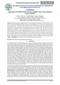
We used the fuzzy inference system (FIS) to build a technique chart to set a mapping relationship between each body-size and weight and the desired optimal tube voltage and tube current based on the desired CTDIvol. All related data and operational parameters used for this chart are based on those provided by [27]. Two optimal technique charts developed by [27] are shown in Tables 1 and 2. Table 1 is for routine pediatric chest CT examinations, and Table 2 is for routine pediatric abdominopelvic CT examinations.
200
TVL (kV), TCU (mAs)
150
TVL (kV) TCU (mAs)
100
TABLE I. WEIGHT-BASED TECH CHART FOR TUBE POTENTIAL AND TUBE CURRENT FOR ROUTINE PEDIATRIC CHEST CT EXAMINATIONS
50
10
20
30
40
50
PW (kg)
Figure 1. Graphic representation of Table I - Pediatric chest CT exam.
III. TABLE II. WEIGHT-BASED TECH CHART FOR TUBE POTENTIAL AND TUBE CURRENT FOR ROUTINE PEDIATRIC ABDOMINOPELVIC CT EXAMINATIONS
FUZZY INFERENCE SYSTEM
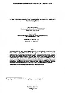
We use desired CTDIvol and given actual body-size of the pediatric patient to be examined as inputs, and the optimal tube voltage and tube current as outputs for a fuzzy inference system. Therefore this is a multi-input and multioutput system. Both inputs and outputs are connected and controlled by the control rules. Fig. 2 shows the block diagram of this fuzzy inference system.
It can be seen from both the tables above that these technique charts only provide relationships or mappings between the body-size and the optimal tube voltage and tube current for three set ranges of body-size viz. 0 ~ 10 kg, 10 ~ 20 kg and 20 ~ 45 kg. In other words, these charts are not complete or continuous because they do not provide all optimal tube voltages and tube currents for each different body-size. These charts can be termed as ‘discrete’ charts. In this study, we will use the fuzzy inference system (FIS) to build complete and continuous technique charts to provide all related optimal tube voltages and tube currents for each different given body-size in real time. In fact, we will use FIS to interpolate the optimal tube voltage and tube current for each specified body-size based on the given charts developed by [27]. To make our study simple, we only used Table 1, for routine pediatric chest CT examinations, as an example to illustrate how to build this flexible and complete technique chart. A graphic representation of Table 1 is shown in Fig. 1. The basic idea behind this development is based on the fact, that the optimal tube potential and tube current are not continuous functions for all different body-sizes located between known body-sizes. Also the relationship between the optimal tube voltage and tube current and different body size is ambiguous, at least it is not a linear one as shown in
197
PW (3)
RadDose TVL (3) (mamdani)
3 rules
CTDI (3)
TCU (3)
System RadDose: 2 inputs, 2 outputs, 3 rules
Figure 2. The block diagram of the fuzzy inference system.
As for the membership functions for two inputs, CTDIvol and patient weight, we utilized gauss2form as the shape for both of them. Similarly, this shape is also used for two outputs, the optimal tube voltage and tube current. The membership functions for both inputs are shown in Fig. 3. The membership functions for both outputs are shown in Fig. 4, respectively. Those membership functions are derived based on the data provided by [27] for routine pediatric chest CT examinations. For this implementation, three control rules are developed based on the input-output conditions listed in [27]. These three control rules are shown in Table 3. The
Light
1
Mid
140
Heavy
120 TCU
Degree of membership
surface of TVL over PW and CTDI is shown in Fig. 5, and the surface of TCU over PW and CTDI is shown in Fig. 6.
0.5
100 80
0 0
5
10
15
20
25
30
35
40
6
45
PW
40
4
30 20
Degree of membership
2
Low
1
Mid
High
CTDI
0
0
PW
Figure 6. Tube current (TCU) over PW and CDTI.
0.5
0 0
1
2
3
4
5
6
IV.
7
CTDI
1
Low
Mid
High
80
100
120
0.5
0 0
20
40
60
IMPLEMENTATION RESULTS
Based on the membership functions of two inputs, Patient Weight (PW) and CT Dose Index (CTDIvol), and membership functions of two outputs, tube voltage (TVL) and tube current (TCU), discussed in the last section, the flexible technique chart for optimal tube voltage and tube current for the given body-size and desired CTDIvol can be easily built and developed. Fig. 7 shows this kind of chart used for routine pediatric chest CT examinations.
Figure 3. Membership functions - inputs, patient weight (PW) and CDTI.
Degree of membership
10
140
Degree of membership
TVL Low
1
Mid
High
0.5
0 0
20
40
60
80
100 TCU
120
140
160
180
200
Figure 4. Membership functions - outputs, tube voltage and tube current. TABLE III.
THREE CONTROL RULES
1. If (PW is Heavy) and (CTDI is High) then (TVL is High) & (TCU is Low) (1) 2. If (PW is Mid) and (CTDI is Mid) then (TVL is Mid) & (TCU is Mid) (1) 3. If (PW is Light) and (CTDI is Low) then (TVL is Low) & (TCU is High) (1)
Figure 7. Technique chart for pediatric chest CT examinations.
TV L
110
100
90
80 6 40
4
30 20
2 CTDI
10 0
0
PW
Figure 8. Technique chart for pediatric abdominopelvic CT examinations.
Figure 5. Tube voltage (TVL) over PW and CDTI.
198
[8]
In Fig. 7, a typical body-size (22.5 kg) and CTDIvol (3.5) are selected. The related optimal tube voltage and tube current are 109 kV and 69.4 mAs, respectively. During the implementation process, the vertical bars on the PW and the CTDIvol in this chart can be moved by the user to either left or right to select the specified body-size and desired CTDIvol based on their actual situations. The optimal tube voltage and tube current can be obtained immediately when the selected input parameters, such as the body-size and desired CTDIvol, are determined by the users. We can also build a similar technique chart using the data provided by [27] for the pediatric abdominopelvic CT examinations using the FIS, which is shown in Fig. 8. V.
[9]
[10]
[11]
[12]
CONCLUSION AND DISCUSSION
A flexible technique chart used to set direct relationship between selected body-size with desired CTDIvol and the optimal tube voltage and tube current is developed in this paper to enable radiologists to easily and practically select the optimal scanning parameters for routine pediatric chest and abdominopelvic CT examinations in clinics. The advantage of using this chart is that the radiologists can select the desired CTDIvol based on the actual given bodysize of the pediatric patient to be examined to obtain the optimal tube voltage and tube current settings from this chart directly and easily.
[13]
[14] [15]
[16]
[17]
ACKNOWLEDGMENT Special thanks should be given to Dr. Lifeng Yu et al, for their permission to allow us to use two tables, Tables 1 and 2, in one of their papers, Optimal Tube Potential for Radiation Dose Reduction in Pediatric CT: Principles, Clinical Implementations, and Pitfalls published in RadioGraphics in May 2011.
[19]
REFERENCES
[20]
[1]
[2]
[3]
[4]
[5]
[6]
[7]
Huda W, Scalzetti EM, Levin G. Technique factors and image quality as functions of patient weight at abdominal CT. Radiology 2000;217(2):430–435. Boone JM, Geraghty EM, Seibert JA, Wootton-Gorges SL. Dose reduction in pediatric CT: a rational approach. Radiology 2003; 228(2):352–360. Siegel MJ, Schmidt B, Bradley D, Suess C, Hildebolt C. Radiation dose and image quality in pediatric CT: effect of technical factors and phantom size and shape. Radiology 2004; 233(2):515–522. Cody DD, Moxley DM, Krugh KT, O'Daniel JC, Wagner LK, Eftekhari F. Strategies for formulating appropriate MDCT techniques when imaging the chest, abdomen, and pelvis in pediatric patients. AJR Am J Roentgenol 2004; 182(4):849–859. Ertl-Wagner BB, Hoffmann RT, Bruning R, et al. Multi-detector row CT angiography of the brain at various kilovoltage settings. Radiology 2004; 231(2): 528–535. Sigal-Cinqualbre AB, Hennequin R, Abada HT, Chen X, Paul JF. Low-kilovoltage multi-detector row chest CT in adults: feasibility and effect on image quality and iodine dose. Radiology 2004; 231(1): 169–174. Funama Y, Awai K, Nakayama Y, et al. Radiation dose reduction without degradation of low-contrast detectability at abdominal multisection CT with a low-tube voltage technique: phantom study. Radiology 2005; 237(3):905–910.
[18]
[21] [22]
[23]
[24]
[25] [26]
[27]
199
Frush DP, Herlong JR. Pediatric thoracic CT angiography. Pediatr Radiol 2005; 35(1):11–25. Wintersperger B, Jakobs T, Herzog P, et al. Aorto-iliac multidetectorrow CT angiography with low kV settings: improved vessel enhancement and simultaneous reduction of radiation dose. Eur Radiol 2005; 15(2):334–341. Holmquist F, Nyman U. Eighty-peak kilovoltage 16-channel multidetector computed tomography and reduced contrast-medium doses tailored to body weight to diagnose pulmonary embolism in azotaemic patients. Eur Radiol 2006; 16(5): 1165–1176. Schueller-Weidekamm C, Schaefer-Prokop CM, Weber M, Herold CJ, Prokop M. CT angiography of pulmonary arteries to detect pulmonary embolism: improvement of vascular enhancement with low kilovoltage settings. Radiology 2006; 241(3): 899–907. Waaijer A, Prokop M, Velthuis BK, Bakker CJ, de Kort GA, van Leeuwen MS. Circle of Willis at CT angiography: dose reduction and image quality—reducing tube voltage and increasing tube current settings. Radiology 2007; 242(3):832–839. Kalva SP, Sahani DV, Hahn PF, Saini S. Using the K-edge to improve contrast conspicuity and to lower radiation dose with a 16-MDCT: a phantom and human study. J Comput Assist Tomogr 2006; 30(3): 391–397. Frush DP. Pediatric abdominal CT angiography. Pediatr Radiol 2008; 38(Suppl 2):S259–S266. Leschka S, Stolzmann P, Schmid FT, et al. Low kilovoltage cardiac dual-source CT: attenuation, noise, and radiation dose. Eur Radiol 2008; 18(9): 1809–1817. Kalender WA, Deak P, Kellermeier M, van Straten M, Vollmar SV. Application- and patient size-dependent optimization of x-ray spectra for CT. Med Phys 2009; 36(3):993–1007. Schindera ST, Nelson RC, Mukundan S Jr., et al. Hypervascular liver tumors: low tube voltage, high tube current multi-detector row CT for enhanced detection—phantom study. Radiology 2008; 246(1): 125– 132. Macari M, Spieler B, Kim D, et al. Dual-source dual-energy MDCT of pancreatic adenocarcinoma: initial observations with data generated at 80 kVp and at simulated weighted-average 120 kVp. AJR Am J Roentgenol 2010; 194(1):W27–W32. Brenner DJ, Hall EJ. Computed tomography: an increasing source of radiation exposure. N Engl J Med 2007; 357(22):2277–2284. Einstein AJ, Henzlova MJ, Rajagopalan S. Estimating risk of cancer associated with radiation exposure from 64-slice computed tomography coronary angiography. JAMA 2007; 298(3):317–323. Huda W. Radiation doses and risks in chest computed tomography examinations. Proc Am Thorac Soc 2007; 4(4):316–320. Gies M, Kalender WA, Wolf H, Suess C. Dose reduction in CT by anatomically adapted tube current modulation. I. Simulation studies. Med Phys 1999; 26(11):2235–2247. Kalender WA, Wolf H, Suess C. Dose reduction in CT by anatomically adapted tube current modulation. II. Phantom measurements. Med Phys 1999;26 (11):2248–2253. Kalra MK, Maher MM, Toth TL, et al. Techniques and applications of automatic tube current modulation for CT. Radiology 2004;233(3):649–657. Kalra MK, Maher MM, Toth TL, et al. Strategies for CT radiation dose optimization. Radiology 2004; 230(3):619–628. Yu L, Li H, Fletcher JG, et al. "Automatic selection of tube potential for radiation dose reduction in CT: a general strategy", Med Phys 2010 Jan; 37(1): 234-43. Lifeng Yu, Michael R. Bruesewitz, Kristen B. Thomas, Joel G. Fletcher, James M. Kofler, and Cynthia H. McCollough, Optimal Tube Potential for Radiation Dose Reduction in Pediatric CT: Principles, Clinical Implementations, and Pitfalls, DOI: 10.1148/rg.313105079, May 2011 RadioGraphics, 31, 835-848.