integral for elliptical Gaussian functions using high-order interpolation and ... With this issue resolved, a small number of mathematical problems barred the way.
Report no. 08/15
Using global interpolation to evaluate the Biot-Savart integral for deformable elliptical Gaussian vortex elements Rodrigo B. Platte Oxford University Computing Laboratory Louis F. Rossi Department of Mathematical Sciences, University of Delaware Travis B. Mitchell 103 Cornell Ave., Swarthmore PA 19081
This paper introduces a new method for approximating the Biot-Savart integral for elliptical Gaussian functions using high-order interpolation and compares it to an existing method based on small aspect ratio asymptotics. The new evaluation technique uses polynomials to approximate the kernel corresponding to the integral representation of the streamfunction. We determine the polynomial coefficients by interpolating precomputed values from look-up tables over a wide range of aspect ratios. When implemented in a full nonlinear vortex method, we find that the new technique is almost three times faster and unlike the asymptotic method, provides uniform accuracy over the full range of aspect ratios. As a proof-of-concept for large scale computations, we use the new technique to calculate inviscid axisymmetrization and filamentation of a two-dimensional elliptical fluid vortex. We compare our results with those from a pseudo-spectral computation and from electron vortex experiments, and find good agreement between the three approaches.
Oxford University Computing Laboratory Numerical Analysis Group Wolfson Building Parks Road Oxford, England OX1 3QD
October, 2008
2
1
Introduction
This paper introduces a new scheme for calculating the Biot-Savart integral of an elliptical Gaussian distribution and compares it to an existing, asymptotic method. The immediate application of these techniques is to rapidly determine the streamfunction and associated derivatives of an elliptical Gaussian vorticity distribution and for a fourth-order viscous core-spreading vortex method. The mathematical problem, concisely stated, is to find the streamfunction ψ where ZZ ∞ 1 log(|~x − ~s|2 )φ(~s)d~s, (1.1a) ψ(~x; σ, a) = − 4π −∞ � � 1 (x2 /a2 + y 2a2 ) φ(~x; σ, a) = exp − , (1.1b) 4πσ 2 4σ 2 where φ is a function describing the shape of the basis function, and σ 2 and a2 is the core size and aspect ratio, respectively, of the basis function. Equation (1.1a) is a restatement of the Biot-Savart integral for the velocity field restricted to a two-dimensional flow: � ∂ψ � ZZ ∞ 1 1 ∂y ~u = R(~x − ~s)φ(~s)d~s (1.2) =− ∂ψ 2π x − ~s|2 − ∂x −∞ |~ where R is a rotation R[x, y]T = [y, −x]T . We capture translations and rotations through symmetries in (1.1a) and apply them to the problem during pre- and post-treatment of the evaluation. An earlier paper [26] describes an asymptotic approach built on top of Lamb’s exact solution for an elliptical patch of vorticity. This is an important problem for two reasons. First, small numbers of elliptical Gaussian vortices may be useful for low order models (see [23, 28, 29] for examples of this approach). Second, elliptical Gaussian basis functions are the foundation of a new class of fourth-order vortex methods for solving the viscous Navier Stokes equations. The use of rigid and deforming elliptical vortex patches dates back to efforts in the 1980s and early 1990s by Teng and his co- authors as a means of improving accuracy by adapting to asymmetric flow geometries [30, 31, 32]. In their later work, patches would deform by following the nearby flow geometry. Meiburg applied a similar approach to simulate shear layers [15], and Ojima and Kamemoto use a hybrid deforming element in a three dimensional vortex code [22]. Deforming elliptical Gaussians capture both linear convection and diffusion in two-dimensions and so they are a natural choice for a high spatial order method. Following this line of reasoning, Moeleker and Leonard performed a series of computational experiments using deforming elliptical Gaussian basis functions for linearized convection-diffusion equations but without the expected increase in spatial accuracy [10, 18]. Shortly afterward, Rossi found an additional requirement for this boost in accuracy that can be satisfied when curvature corrections are applied to the velocity field, and demonstrated that methods using deforming blobs will outperform methods using rigid blobs even at moderate problem sizes [24, 25]. With this issue resolved, a small number of mathematical problems barred the way to a full-fledged high order viscous vortex method. One of them is a fast, effective means
3 of evaluating the streamfunction and its first three derivatives for the elliptical Gaussian as described in (1.1). The basis functions are deformed by local flow deviations, and the velocity field correction requires that one calculate the velocity curvature (see Appendix A for an overview of the dynamical system), so calculating the streamfunction and its derivatives is critical to an effective computation. While there are a variety of methods that can be applied for integrating axisymmetric distributions due to the obvious reduction in dimensionality, the non-axisymmetric problem is more general and challenging. Rossi proposed an accurate and effective means of solving this problem, verified the full nonlinear convergence of the vortex method and developed a fast summation algorithm for elliptical Gaussians in the far field [26]. In this paper, we focus on the direct evaluation of elliptical Gaussians in the near field, and we present a significant improvement over this earlier solution. This manuscript, describing a new, more accurate and more efficient global method for solving (1.1), is organized as follows. This section of the paper describes the problem in its broader context. We briefly review the asymptotic method for evaluation of the streamfunction in Section 2. Section 3 describes the new technique for evaluating the streamfunction. Section 4 quantitatively compares the existing asymptotic method and the new evaluation technique to one another. We demonstrate full non-linear converence to the exact solution of the Navier-Stokes equation for the test problem. Section 5 uses the new method to compute a challenging inviscid filamentation problem as a proofof-concept, and we compare our results with a standard pseudo-spectral method and electron vortex experiments [17]. Our results and findings will be summarized in Section 6.
2
Review of asymptotic method
Both the new technique and the asymptotic method introduced in [26] rely upon Lamb’s expression for the streamfunction of an elliptical patch with axes l1 and l2 [7]. � � 2 y2 1 x (x, y) ∈ E(l1 , l2 ) 2π(l1 +l2 ) l1 + l2 , � � � x2 + y 2 � ψ = (2.1a) α β 1 + ln lα+β , (x, y) ∈ / E(l , l ) 2π 1 2 α+β 1 +l2 q l12 + ξ, (2.1b) α = q β = l22 + ξ, (2.1c) � 2 � � 2 � x y 1 = + 2 , (2.1d) 2 l1 + ξ l2 + ξ where E(l1 , l2 ) is the support of the ellipse and ~u =
�
u v
�
=
�
− ∂ψ ∂y ∂ψ ∂x
�
.
4 Following the procedure in [26], we can express the streamfunction of an elliptical Gaussian at a point (x∗ , y∗ ) as Z ∞ Z R∗ 2 ψ2 ∂R φdR, (2.2a) ψ1 ∂R φR dR − ψ(x∗ , y∗ ) = − 0
R∗
1 −R2 /4σ2 e . φ(R; σ, a) = 4πσ�2 � y∗ 2 x∗ 2 � � + β 1 α α+β , ψ1 = + ln 2 α+β Ra + R/a
(2.2b) (2.2c)
2
1 xa∗ + y∗ 2 a ψ2 = , 2 a + 1/a p α = R2 a2 + ξ, r R2 β = + ξ. a2
(2.2d) (2.2e) (2.2f)
2
where ρ∗ 2 = x∗ 2 + y∗ 2 , R∗ 2 = xa∗2 + y∗ 2 a2 and � s� � � �2 � 1 1 1 ξ= ρ∗ 2 − R2 a2 + 2 + R2 a2 + 2 − ρ∗ 2 + 4R2 (R∗ 2 − R2 ) . 2 a a
(2.3)
The second integral poses no difficulty at all because ψ2 is not a function of R. However, there is no known expression for the first integral in terms of elementary functions, and this is where the challenge lies. The asymptotic method approximates ψ1 in powers of the small parameter ǫ=
a−1 a+1
which reduces the first part of the integral in (2.2a) to moments of a one-dimensional Gaussian. The coefficients of each of the moments depend upon x∗ , y∗ , a and σ. Successive moments can be obtained through a recurrence relation, so the method is both fast and accurate. Unfortunately, it requires many terms in the large aspect ratio limit, so the evaluation of the moments becomes unstable at high orders due to catastrophic cancellations.
3
The high-order interpolation method with domain decomposition
The asymptotic approximation given in §2 converges most rapidly in the small ǫ limit and so is most accurate when vorticity blobs are nearly isotropic. On the other hand, Marshall and Grant derived an approximation for the velocity field when blobs are highly
5 anisotropic in [13]. In this section we explore a high-order interpolation technique that uses domain decomposition for the fast evaluation of the Biot-Savart integral for all core aspect ratios — although we restrict our implementation to a ∈ [0.1, 10], since larger aspect ratios would be better handled by the closed form expressions derived in [13]. Without loss of generality, in this section, we assume σ ≡ 1 and use the notation ψ(~x; a) ≡ ψ(~x; 1, a). Notice that ψ(~x; σ, a) =
1 ψ(~x/σ; a) + Cσ,a , σ
where Cσ,a does not depend on ~x and does not affect the velocity field; we set Cσ,a ≡ 0 in our implementation. Moreover, we restrict our computations to a ≥ 1, x > 0, and y > 0, since ψ(x, y; 1/a) = ψ(y, x; a)
and
ψ(y, x; a) = ψ(|y|, |x|; a).
The main idea is to recast the parameter a as a variable. Because the Biot-Savart integral is a smooth function of ~x, accurate approximations of ψ can be obtained with the polynomial expansion, ψ(x, y; a) =
Ny Nx X X
λnx ,ny (a) xnx y ny ,
x > 0, y > 0, a > 1.
(3.1)
nx =0 ny =0
The coefficients λnx ,ny are functions of the core aspect ratio in contrast to the asymptotic method where the coefficients depend upon x, y and ǫ (or a). These coefficients are computed for several values of a, and for each given aspect ratio, we compute them so that (3.1) interpolates the values of ψ computed using (2.2a). These coefficients were obtained only once and stored in files for future use, since this operation requires time consuming computations. Because each λnx ,ny is a smooth function of a, when evaluations are needed for arbitrary values of a, new coefficients can be found by a fit of the coefficients already computed. Figure 1 depicts the behavior of ψ as a function of the three variables x, y, and a. Contours are shown for ψ = 0 to ψ = 0.3 in increments of 0.01. Notice that variations of ψ with respect to a are more drastic for smaller values of a rather than larger values. The contours in the third row of this figure show that ψ has elliptic level curves near the origin, but circular for large values of x and y, since ψ → c log(x2 + y 2 ) as x2 + y 2 → ∞. The number of operations required to evaluate (3.1) and its derivatives is O(Nx Ny ). For fast evaluations, therefore, we need Nx and Ny to be relatively small numbers. In order to accomplish this without compromising accuracy, we resort to domain decomposition. More specifically, we split our computational domain in 13 rectangular regions shown in Fig. 2. The exact boundary for each subdomain is presented in Table 1. Notice that the subdomains are scaled with a since the resolution required in parts of the domain depend on the core aspect ratio. These subdomains were obtained by trial and error so that (3.1) is accurate to about 10 digits with Nx = Ny = 16 in each region. For the far field approximation, x > 40.5a or y > 40.5a, we use the isotropic approximation
6
Contours of ψ (x, 2, a)
8
8
8
6
6
6
4
4
4
2
2
2
5 10 x Contours of ψ (0, y, a)
0
5 10 x Contours of ψ (2, y, a)
0
5 10 x Contours of ψ (5, y, a)
10
10
8
8
8
6
6
6
a
10
a
4
4
4
2
2
2
0
5 10 y Contours of ψ (x, y, 1)
0
5 10 y Contours of ψ (x, y, 3)
0
5 10 y Contours of ψ (x, y, 5)
10
10
5
5
5
0 0
y
10
5 x
10
0 0
y
a
a
10
0
y
Contours of ψ (x, 5, a)
10
a
a
Contours of ψ (x, 0, a) 10
5 x
10
0 0
5 x
10
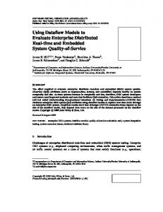
Figure 1: Contour levels of ψ. Top row: contours for fixed values of y; middle row: contours for fixed values of x; and bottom row: contours for fixed values of a.
7
ψ ∼ c log(x 2 + y 2 )
y
40.5a
11.5a
0
0
11.5a
x
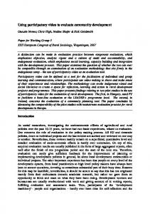
40.5a
Figure 2: Domain decomposition in the xy-plane. ψ = c1 log(x2 +y 2). In our implementation, therefore, we use a piecewise polynomial representation of the solution and replace (3.1) with 13 equivalent expressions each defined only on one subdomain. It is well known that high-order polynomial interpolation is well-conditioned only on nodes that are clustered more densely near the boundaries of the domain [6]. In computing the polynomial coefficients, therefore, we mapped each domain to [−1, 1] × [−1, 1] and used the Chebyshev points depicted in Fig. 3; see [33] for details. We point out that we use monomials in (3.1), rather than orthogonal polynomials, because of their fast evaluation — since the degree of the polynomials is relatively small, the interpolation process is not ill-condtioned. The coefficients in (3.1) are computed in each individual subdomain for several values of a. Because ψ varies more rapidly with respect to a when a ≈ 1, we use a nonuniform distribution of values of a to compute these coefficients. More precisely, we compute them for 700 aspect ratios between 1 and 10, such that the distance between two neighboring values grows linearly as a increases; i.e., aj = 1 + 9(j/699)2 , j = 0 . . . 699. Fig. 4 shows the values of a used in our computations. Due to the large number of points, we only show points between 1 and 1.1. Because we have a large number of samples of coefficients, a low order approximation in the direction of the parameter a yields accurate results. In fact, the errors in the approximations are in general due to the approximations in the x and y direction. For an arbitrary value of a in [aj , aj+1] the coefficients are computed using the weighted average, λnx ,ny (a) =
(a − aj )λnx ,ny (aj ) + (aj+1 − a)λnx ,ny (aj+1 ) . aj+1 − aj
(3.2)
8
Subdomain 1 2 3 4 5 6 7 8 9 10 11 12 13
xmin 0 0 0 0 0 5a 5a 5a 5a 5a 11.5a 0 11.5a
xmax 5a 5a 5a 5a 5a 11.5a 11.5a 11.5a 11.5a 11.5a 40.5a 11.5a 40.5a
ymin 0 0.5 1 3 √ 7 a 0 0.5 1 3 √ 7 a 0 11.5a 11.5a
ymax 0.5 1 3 √ 7 a 11.5a 0.5 1 3 √ 7 a 11.5a 11.5a 40.5a 40.5a
Table 1: Rectangular subdomains in the xy-plane.
y
1
−1 −1
x
1
Figure 3: Chebyshev grid: 17 × 17 points.
a=1
a = 1.1
Figure 4: Nonuniform sampling values of a in [1, 1.1]. The spacing between values grows linearly.
9 In our algorithm, the coefficients are stored in 13 files, each corresponding to a subdomain in Table 1. Each file stores 700 × 17 × 17 double precision coefficients, requiring about 5MB of memory. The files are loaded only once in the beginning of an execution. The number of operations required for the evaluation of ψ for an input (x, y, a) is, therefore, dominated by approximately 2 × 289 products in (3.2) and approximately 3 × 289 products to evaluate the polynomial in (3.1). Derivatives of ψ are obtained by differentiating (3.1). The computation of higher derivatives usually result in loss of accuracy. Although our implementation evaluates the Biot-Savart integral to an error of O(10−10), approximately one accurate digit is lost for each derivative computed. In order to estimate the error in the second derivatives, we use the Poisson equation � �� � 1 x2 1 2 2 = 0, (3.3) exp − +y a ψxx + ψyy − 4π 4 a2 √ which is solved by (1.1a). The residual in (3.3) when a = 5 is shown on the left plot of Fig. 5. This gray scale map corresponds to the logarithm of the residual, showing an error of O(10−8) on the second derivatives of ψ. Similarly, we can estimate the error in the third derivatives using the equation � �� � � 1 �x 1 x2 2 2 2 ψxxx + ψyyy + ψxyy + ψxxy + = 0, (3.4) + ya exp − +y a 8π a2 4 a2 which is obtained by differentiating (3.3) with respect to x and y and adding the resulting equations. The residual in (3.4) is shown on the right plot of Fig. 5, which presents an error of O(10−7) near the origin for third derivatives. Similar pattern has been observed for other values of a.
4
Comparisons
The new evaluation method stably provides accurate estimates of the Biot-Savart integral with spectral accuracy, independent of the aspect ratio. The asymptotic method has polynomial convergence in powers of ǫ which depends upon the aspect ratio. There are some notable implementation differences. The computational simplicity of the asymptotic method allows the streamfunction coefficients to be calculated on-the-fly during a computation. The cost associated with calculating the coefficients for the spectral scheme is prohibitive, so we precomputed coefficient values for in regular increments of a and then use these tables to interpolate coefficients for any value of a during the computation. In these comparisons, the asymptotic coefficients are calculated as needed while the spectral coefficients are pre-calculated. The simplest comparison is to compare CPU times for streamfunction calculations. These measurements were performed on an Intel Core 2 Duo 1.862 GHz CPU running Linux. We compiled the standalone code with GNU C compiler, gcc, version 4.1.1 with the -O3 optimization flag set. We excluded initializations and file I/O from the
10
Figure 5: Estimated error in second and third derivatives of ψ for a = of the residual in (3.3). Right: log10 of the residual in (3.4).
√
5. Left: log10
11 Method Asymptotic Spectral
Far field (MP) 9.2 9.3
Near field (direct) 287.4 113.7
Velocity total 296.7 123.7
Table 2: Average CPU seconds dedicated to different tasks in the velocity computation over five steps through the vortex method algorithm for N = 6917. All times are measured in CPU seconds. The reported times for multipole (MP) summation include both the calculation of multipole coefficients and the summation of far field effects. The cost of the velocity computation includes lesser tasks so the total of near and far field costs do not always add up to the total. comparison. The test consisted of a calculation of the streamfunction as well as its first, second and third derivatives on a 100 × 100 mesh covering the domain [12σ, 12σ]2 for an elliptical Gaussian with ǫ = 0.25 using a sixth order expansion with the asymptotic method and compared it to the algorithm described in §3 using 172 coefficients. The asymptotic technique required 0.3 CPU seconds to complete the computation whereas the spectral technique required 0.12 CPU seconds, a reduction of almost 1/3. The asymptotic method had the same accuracy reported in [26] whereas the new method was numerically indistinguishable from the high precision quadrature used as the reference. However, this does not paint a complete picture in practice. To be competitive, vortex calculations must include some form of fast summation that separates the near and far field. The methods discussed in this paper are limited to direct evaluations in the near field. Even for large-scale computations, the majority of effort will be expended on direct evaluations. In Table 2, the computational costs are broken down between near and far field. For this test, we used a test problem with N = 6917 basis functions (corresponding to the third most refined run of five runs shown in Fig. 6). The improvement in performance is substantial. Tests over different problem sizes scale with N, and when parallelized, scale with the number of CPUs. A standard test for a vortex code is the steady diffusion of an axisymmetric distribution of vorticity. We will use a Lamb-Oseen vortex � ω(~x, 0) = 4 exp −4|~x|2 , (4.1) where ω is the vorticity field. The exact solution is � � 1 |~x|2 ω(~x, t) = 1 exp − 1 , + 4t/Re + 4t/Re 4 4
(4.2)
where Re is the Reynolds number of the flow. This is a strong test for any method’s ability to capture convective forces correctly because the streamlines are concentric. A properly implemented low-order vortex method should nail this problem to within numerical precision regardless of the core size because it ignores linear flow deviations that cross streamlines. This is a special advantage unique to flow with circular streamlines. For the fourth-order method, the Lamb-Oseen problem is not so special and
12
ECCSVM convergence: Lamb-Oseen test problem 4
Re = 10 - Sixth order asympototic and spectral streamfunction -4
0
T=
-1
10
T=
1 .0 X
2
-4
1.4
0 X1
-4
0
l2 error
1 T= T=
-2
10
-5
0
1 6X
-3
10
Asymptotic streamfunction technique Spectral streamfunction technique Fourth order (slope = 2) -4
10
-3
-2
10
10 2
Figure 6: Results from the spectral and asymptotic streamfunction evaluation at times T = 6×10⁻⁵, 10−4 , 1.4×10⁻⁴ and 2×10⁻⁴. Only the finer three data points are available for T = 2.0 × 10⁻⁴ because the asymptotic velocity evaluations experience catastrophic cancellation errors when the aspect ratios grow large.
spatial errors are finite and measurable. We performed a direct comparison between the asymptotic and spectral technique as shown in Fig. 6. For early evolution times, both methods produce comparable precision and exhibit fourth order accuracy. However, at later times, the basis functions become more deformed and the asymptotic streamfunction approximation becomes less precise. At T = 2.0 × 10⁻⁴ for large hσi2 i, the aspect ratio becomes so large that the sixth-order expansion becomes numerically unstable P and 2 the algorithm halts. Typical growth curves for the average aspect ratio (1/N) N i=1 ai , PN PN circulation weighted average aspect ratio (1/ i=1 γi ) i=1 γia2i and maximum aspect ratio are shown in Fig. 7. The maximum aspect ratio will determine whether or not the asymptotic technique will become numerically unstable, but the circulation averaged aspect ratio is a better indicator of the overall precision of the method. The new scheme works well under all conditions.
13
Basis function aspect ratio growth 6
Aspect ratio
5
Average Weighted average Maximum
4
3
2
1 0.0
-5
5.0×10
-4
1.0×10 Time
-4
1.5×10
-4
2.0×10
Figure 7: Typical aspect ratios for the Lamb-Oseen test problem as a function of time for σ 2 = 4 × 10⁻⁴ at t = 0 using the asymptotic technique. Initial conditions using other initial blob core sizes exhibit similar aspect ratio growth curves.
5
A computational demonstration using laboratory experiments of vortex filamentation
Low order vortex methods have been successful in a wide range of scientific and engineering applications. High-order methods are more complex and therefore more difficult to implement in large scale computations. In this section, we present a proof-of-concept calculation to show that the new method is suitable for large-scale computational challenges. The demonstration will consist of the vortex method calculation, a pseudospectral method calculation and a physical experiment. More information about a direct comparisons between pseudo-spectral methods and vortex methods can be found in [5]. Similarly, quantitative comparisons between pseudo-spectral and another Lagrangian method called contour surgery have been explored as well [8]. We performed a study of filamentation in a vorticity distribution based on that used in the 1987 paper by Melander, McWilliams and Zabuski [16]. The initial conditions are an elliptical vortex with a smooth transition between rotational and irrotational fluid. This relatively simple initial condition has continuous derivatives everywhere and a single parameter ((Ro − Ri )/Ro ) that characterizes the sharpness of the interface. We
14 begin with an axisymmetric vorticity distribution: 1, � r ≤ Ri , � i , Ri < r < Ro , gaxi (r, Ri , Ro ) = 1 − fκ Rr−R o −Ri 0, r ≥ Ro , � �� � κ 1 fκ (r) = exp − exp ,0 ≤ r ≤ 1 r r−1 1 κ = e2 ln(2) 2
(5.1a)
(5.1b) (5.1c)
The original paper [16] is not specific on how one translates gcirc into an elliptical distribution, but we take the obvious course and define ! r 2 x + y 2a2 , Ri , Ro , (5.2) g(x, y, Ri, Ro , a2 ) = gaxi a2 where a2 is the aspect ratio. The specific initial conditions for the proof of concept are ω(x, y, 0) = 20 g(x, y, 0, 1, 2),
(5.3)
corresponding specifically to one of the cases studied in [16]. To perform vortex method computations, we discretized (5.3) using N = 11, 269 axisymmetric basis functions with a core size of σ 2 = 3.125 × 10⁻³. The number of basis functions is roughly equivalent to the 1282 Fourier modes used in [16], but the vortex computation is grid-free and requires no hyperviscosity to damp the artificial growth of high frequency components. We chose a timestep of 10−3 and used third order AdamsBashforth to integrate trajectories for the vortex method. However, the deforming basis functions continue to elongate over time. If unchecked, the deformation will lead to a catastrophic loss of spatial accuracy. We solved this problem by regularly reprojecting the distribution back onto a configuration of axisymmetric basis functions. While there is no viscosity or hyperviscosity introduced into the dynamics of the problem, reprojection with a fixed core size removes higher-frequency components and thus can be interpreted as a form of low-pass filter. There are a number of ways to perform this type of remeshing including using M-functions [19, 20, 21] or radial basis functions [1, 2]. Instead, we borrow a technique used in image processing. If we directly project an existing solution onto a regular array of axisymmetric basis functions by choosing γi = f (~xi )h2
(5.4)
where f is an existing solution generated by an arbitrary configuration of basis functions, ~xi is the location of the ith new basis function on a regular array, γi is the circulation of the new basis function which will replace the existing one and h is the mesh width, we will generate a blurred representation of f . The overlap ratio β = h/σ is connected
15 to the accuracy of the basis function interpolation. The blurring corresponds to the solution ω(~x, t) at t = σ 2 of the system ωt = ∇2 ω,
ω(~x, 0) = f.
(5.5)
One can see this because (5.4) approximates a convolution with the fundamental solution to (5.5), N X f (~xi )h2 i=1
4πσ 2
|~x − ~xi |2 exp − 4σ 2 �
�
≈
ZZ
∞ −∞
� � |~x − ~y |2 f (~y ) exp − d~y = ω(~x, σ 2 ) 4πσ 2 4σ 2
(5.6)
This type of blurring has been addressed successfully with a number of algorithms. A detailed review of PDE methods for deblurring is beyond of the scope of this paper, and we refer the reader to sources such as [27] for a more thorough treatment. We note that our needs differ from image enhancement because we seek to reverse a convolution. Methods such as shock filters may help accentuate contours, but do not necessarily serve the purpose of accurately reproducing the vorticity field. Formally reversing the heat equation for an arbitrary fixed time is an ill-posed problem and explicit numerical methods will amplify high frequency components. However, we are seeking to reverse (5.5) given data at time t = σ 2 where σ is our small numerical parameter. If we refine the reprojection mesh to improve our spatial resolution, we decrease the total integration time for the backward heat equation. Our refinement method is fairly simple. 1. We begin with a vorticity field ω that is represented by any set of basis functions. The configuration may be strained or some basis functions might be extremely elongated. 2. We calculate the vorticity on a regular grid. 3. We calculate γ ′ at each mesh point on the regular grid using (5.4) where h = σ is the mesh spacing. 4. We calculate ∇2 γ ′ using sixth order finite differences. 5. We calculate γ at each mesh point by solving the reverse heat equation (Solve (5.5) backward in time) using fourth order Runge-Kutta. The γ’s are the circulations of a new configuration of axisymmetric basis functions arranged on the regular grid that replace the original configuration. For detailed analysis and diagnostics of the deblurring method, see [3]. For numerical comparison, we also implemented a pseudo-spectral method. We used the algorithm described in [14], which has been used for the simulation of vortex filamentation in previous studies [9, 16]. The method is based on Fourier expansions of the vorticity and stream functions and solves ωt + ψx ωy − ψy ωx = −νh ∆2 ω,
∆ψ = −ω,
16 where νh ∆2 ω is a hyperviscosity term. The simulation was performed in the doubleperiodic domain with two domains at the same resolution to understand the impact of far field boundary conditions. We performed one calculation on the domain [−π, π]×[−π, π] using a 256 ×256 grid and another on the domain [−2π, 2π]×[−2π, 2π] using a 512 ×512 grid. Both used a hyperviscosity νh = 10−7 . To advance in time, we used a third order Adams-Bashforth scheme with ∆t = 0.0005. For the problem at hand, both methods performed well and require modest computational resources. Plots of the results obtained from both numerical schemes are presented in Fig. 9. Both calculations resolve the position and shape of the filaments and the core and are in agreement with each other. A systematic comparison between both schemes is beyond the scope of this article. As pointed out in [5], the performance of each method is very much dependent on the way boundary conditions are treated and on the driving forces of the fluid motion. While periodic boundary conditions are optimal for spectral methods, since the solution of the Poisson equation is trivial, imposing other restrictions at boundaries substantially increases the cost of these methods. However, for problems on unbounded domains, spectral schemes often require artificial boundary conditions such as absorbing boundary layers [12]. On the other hand, many particle methods, including the one used in this paper, naturally satisfy the boundary conditions on unbounded domains. Another way to address this issue which we did not pursue is to sacrifice spectral accuracy and use finite differences in the radial direction (remapping [0, ∞) onto a finite interval) together with a spectral discretization in the azimuthal direction [4]. For these calculations, the pseudo-spectral calculation with the [−π, π] smaller domain produced significant overrotation, roughly 17 degrees, in the simulation. This maximum discrepency is reduced to roughly 3 degrees at the end of the 1.65 second time simulation using the [−2π, 2π] larger domain. The raison d’etre of many large scale scientific computations is to simulate a physical process. To complement our numerical proof-of-concept, we also present a comparison with laboratory experiments on electron vortices, which are electron plasma columns contained within a Penning trap [17]. In the operating regime of the experiments, where fast electron motions in the axial direction average over axial variations and the 2D E × B drift approximation is valid, to first order the columns evolve according to the 2D Euler equations. The columns therefore evolve as would vorticity in an incompressible and inviscid 2D fluid contained in a circular tank with a free-slip boundary condition. A schematic of the experimental apparatus used is shown in Fig. 8. A column of electrons of temperature T ≃ 1 eV is confined inside a series of conducting rings of wall radius Rw = 2.88 cm and confinement length Lc = 36.0 cm, in a uniform axial magnetic field Bz = 454 Ga. The rings are segmented six-fold into 60◦ sectors to allow for vortex manipulation through the application of non-axisymmetric electric fields. The magnetic field provides radial confinement, and negative confinement voltages of Vc = −24 V applied to end gate rings provide axial confinement. The x, y flow of the electrons is well described by the 2D drift Poisson equations, with the vorticity of the flow, ω ≡ zˆ · ∇ × v = ( 4πec )n = 0.399 n, proportional to the 2D electron density [17]. B In the measurements an electron column is injected and trapped, then made elliptical by the application of precise voltage waveforms onto two opposing ring sectors. To study
17
Figure 8: Side and end view schematics of the cylindrical electron Penning trap geometry. Technique Asymptotic Spectral
Coefficient var’s Precomputation req’d x, y, ǫ or a No a Yes
Accuracy ǫn exp(−c n)
Performance Slower Faster
Table 3: A summary of features for the two different methods for calculating the BiotSavart integral. There are implementation, accuracy and performance differences. the subsequent evolution at a specific time, the electron column is dumped axially onto a phosphor screen biased to 9 kV, and an image is recorded with a CCD camera of the emitted light, which is proportional to the electron line charge number distribution N(x, y). From the line charge, the electron temperature, and the trap geometry, we calculate the equivalent 2D density n(x, y) and then the vorticity ω(x, y) using ω = 0.399 n. Because the density measurement is destructive, multiple shots beginning with identical initial conditions are required to follow the time evolution. We adjusted the electron source and manipulated the injected electron column to create a density initial condition similar to that specified by (5.3). We plot the measured vorticity at three subsequent times in the bottom row of Fig. 9. To compare results, we rotate the vorticity fields from the computational experiments by 124.6 degrees so that the first frame of the each time series is horizontal. The strong agreement between laboratory and numerical experiments in this inviscid study demonstrate the value of high-order computations, even with moderate computational resources. This measurement and others like it are being used to study the axisymmetrization of vortices. This particular example highlights the central role filamentation plays in asymmetrization where the core and filaments interact strongly to reduce the overall aspect ratio [16]. This process is ubiquitous in physical flows and with 2D elliptical vortices is often the dominant axisymmetrization process, although mode instabilities can also play a role [11].
6
Conclusion
In summary, we have presented a new method for approximating the Biot-Savart integral of an elliptical Gaussian basis function. This technique brings about a major improvement in computational efficiency and the range of applicability of high order
18 vortex methods using deforming basis functions. In particular, the new scheme for approximating the streamfunction offers several distinct advantages over the asymptotic scheme which was the only technique available prior to this work. The key differences in implementation, accuracy and performance are summarized in Table 3. The evaluation method performs as well as the asymptotic technique for small or moderate aspect ratios, but for larger aspect ratios, errors accumulate and destroy the extra precision of the high order vortex method when using the asymptotic method. Moreover, the method is faster and since direct evaluations are the dominant part of a vortex computation, even when using fast summation, the new technique boosts the performance of the full vortex method considerably. We have demonstrated the viability of the high order method for large scale computations. While low order axisymmetric methods allow fast, analytic evaluation of the streamfunction, the high order method will always outperform low order methods eventually, and the transition often occurs at moderate problem sizes (see [25] for example). Using a simple remeshing scheme, we have performed a simple vortex filamentation simulation which shows strong agreement with electron vortex experiments and a pseudo-spectral method. In short, the new evaluation technique described in this paper augments and expands the capability of high spatial order vortex methods for viscous flow calculations.
7
Acknowledgements
We performed the sample simulations in this manuscript using the University of Delaware Department of Mathematical Science’s Opteron cluster supported by NSF SCREMS DMS-0322583. TBM was supported by National Science Foundation Grant No. PHY0140318 and U.S. Department of Energy Grant No. DE-FG02-06ER54853. LFR and RBP wish to acknowledge the UD Mathematical Sciences High Performance Computing Roundtable that brought us together to work on this problem.
Appendix A Overview of the high-order vortex method using elliptical Gaussian basis functions In this section, we formulate the dynamics for a vortex method using elliptical Gaussian basis functions. Generalizing (1.1b), we include parameters for the circulation, position, core size, aspect ratio and orientation of the basis function as follows. � � � � 1 |Aθ,a~x|2 cos θ/a sin θ/a φσ,a,θ (~x) = . (A.1) exp − , Aθ,a = −a sin θ a cos θ 4πσ 2 4σ 2 To briefly summarize the systematic derivation in [24], we represent the vorticity field as a linear combination of basis functions, ω=
N X i=1
γi φσi ,ai ,θi (~x − ~xi ).
(A.2)
19 We require that the basis functions satisfy evolution equation ∂t φ + (~u + D~u ~x)φ =
1 2 ∇ φ Re
(A.3)
where ~u is a known velocity field determined by the Biot-Savart integral discussed in this paper evaluated at the basis function centroid and D~u, is the matrix of partial derivatives of the velocity field ~u. Inserting (A.1) into (A.3) yields the following equations: d ~xi = ~u(~xi ) + σi2 (~uxx (~xi )Mxx + 2~uxy (~xi )Mxy + ~uyy (~xi )Myy ) , dt 1 d 2 (σi ) = (a2 + a−2 i ), dt 2 Re i d 2 1 (ai ) = 2[d11 (c2i − s2i ) + (d12 + d21 )si ci ]a2i + 2 (1 − a4i ), dt 2σ Re � � −2 d21 − d12 d21 + d12 2 (ai + a2i ) d 2 θi = + (si − ci ) + 2d11 si ci . 2 dt 2 2 (a−2 i − ai )
(A.4a) (A.4b) (A.4c) (A.4d)
Here, dij are the constituent elements of D~u, the matrix of partial derivatives of the velocity field ~u, ci = cos(θi ), si = sin(θi ), and the M’s represent velocity field curvatures: 2 2 2 2 Mxx = c2i a2i + s2i /a2i , Mxy = ci si (a2i − a−2 i ), Myy = ci /ai + si ai .
(A.4e)
Basis function deformations are driven by D~u, the local flow deviations. Notice that the velocity field of each basis function is not the velocity field measured at the centroid but rather the velocity field with a curvature correction. This is necessary if one is to achieve fourth order spatial accuracy, so accurate calculation of the velocity field and its derivatives is essential.
Appendix References [1] L. A. Barba. Spectral-like accuracy in space of a meshless vortex method. In ECCOMAS Thematic Conference on Meshless Methods., July 2005. [2] L. A. Barba, A. Leonard, and C. B. Allen. Advances in viscous vortex methods meshless spatial adaption based on radial basis functions. Int. J. Num. Methods in Fluids, 47:387–421, 2005. [3] L. A. Barba and L. F. Rossi. Global field interpolation for particle methods. Submitted to J. Comput. Phys., 2008. [4] J. D. Buntine and D. I. Pullen. Merger and cancellation of strained vortices. J. Fluid Mech., 205:263–295, 1989. [5] G.-H. Cottet, B. Michaux, S. Ossia, and G. VanderLinden. A comparison of spectral and vortex methods in three-dimensional incompressible flows. J. Comp. Phys., 175:1–11, 2002.
20 [6] P. J. Davis. Interpolation and approximation. Dover Publications Inc., New York, 1975. [7] H. Lamb. Hydrodynamics, chapter IV, VII, pages 84–86, 232–233. Cambridge University Press, 1993. [8] B. Legras and D. G. Dritschel. A comparison of the contour surgery and pseudospectral methods. J. Comp. Phys., 104:287–302, 1993. [9] B. Legras, D. G. Dritschel, and P. Caillol. The erosion of a distributed twodimensional vortex in a background straining flow. J. Fluid Mech., 441:369–398, 2001. [10] A. Leonard. AIAA 97-0204: Large-eddy simulation of chaotic convection and beyond. In 35th Aerospace Sciences Meeting & Exhibit. American Institute of Aeronautics and Astronautics, 1997. [11] A. E. H. Love. On the stability of certain vortex motions. Proc. London Math. Soc., 25:18–42, 1893. [12] A. Mariotti, B. Legras, and D. G. Dritschel. Vortex stripping and the erosion of coherent structures in two-dimensional flows. Physics of Fluids, 6(12):3954–3962, 1994. [13] J. S. Marshall and J. R. Grant. A method for determining the velocity induced by highly anisotropic vorticity blobs. J. Comp. Phys., 126:286–298, 1996. [14] J. C. McWilliams. The emergence of isolated coherent vortices in turbulent flow. J. Fluid Mech., 146:21–43, 1984. [15] E. Meiburg. Incorporation and test of diffusion and strain effects in the twodimensional vortex blob technique. J. Comp. Phys., 82:85–93, 1989. [16] M. V. Melander, J. C. McWilliams, and N. J. Zabusky. Axisymmetrization and vorticity-gradient intensification of an isolated two-dimensional vortex through filamentation. J. Fluid Mech., 178:137–159, 1987. [17] T. B. Mitchell and C. F. Driscoll. Electron vortex orbits and merger. Phys. Fluids, 8(7):1828–1841, 1996. [18] P. Moeleker and A. Leonard. Lagrangian methods for the tensor-diffusivity subgrid model. J. Comp. Phys., 167:1–21, 2001. [19] J. J. Monaghan. Why particle methods work. SIAM J. Sci. Stat. Comput., 3(4):422– 433, 1982. [20] J. J. Monaghan. Extrapolating B-splines for interpolation. J. Comp. Phys., 60:253– 262, 1985.
21 [21] J. J. Monaghan. Smoothed particle hydrodynamics. Ann. Rev. Astron. Astrophys., 30:543–574, 1992. [22] A. Ojima and K. Kamemoto. Numerical simulation of unsteady flow around three dimensional bluff bodies by an advanced vortex method. JSME Int. J. Series B Fluids and Therm. Mixing, 43(2):127–135, May 2000. [23] G. Riccardi and R. Piva. Motion of an elliptical vortex under rotating strain: conditions for asymmetric merging. Fluid Dyn. Res., 23(2):63–88, 1998. [24] L. F. Rossi. Achieving high-order convergence rates with deforming basis functions. SIAM J. Sci. Comput., 26(3):885–906, 2005. [25] L. F. Rossi. A comparative study of lagrangian methods using axisymmetric and deforming blobs. deforming blobs. SIAM J. Sci. Comput., 27(4):1168–1180, 2006. [26] L. F. Rossi. Evaluation of the biot-savart integral for deformable elliptical gaussian vortex elements. SIAM J. Sci. Comput., 28(4):1509–1532, 2006. [27] L. I. Rudin, S. Osher, and E. Fatemi. Nonlinear total variation based noise removal algorithms. Physica D, 60:259–268, 1992. [28] B. N. Shashikanth and P. K. Newton. Geometric phases for corotating elliptical vortex patches. J. Math. Phys., 41(12):8148–8162, 2000. [29] D. Sipp, D. Fabre, S. Michelin, and L. Jacquin. Stability of a vortex with a heavy core. J. Fluid Mech., 526:67–76, 2005. [30] Z.-H. Teng. Elliptic-vortex method for incompressible flow at high Reynolds number. J. Comp. Phys., 46:54–68, 1982. [31] Z.-H. Teng. Variable-elliptical-vortex method for incompressible flow simulation. J. Comp. Math., 4(3):255–262, 1986. [32] Z.-H. Teng. Convergence of the variable-elliptic-vortex method for Euler equations. SIAM J. Num. Anal., 32(3):754–774, June 1995. [33] L. N. Trefethen. Spectral Methods in Matlab. Society for Industrial and Applied Mathematics, 2000.
22
Figure 9: Computational and experimental measurements of vorticity. The top row plots are simulations using the vortex method. The middle row plots are pseudo-spectral computations. The bottom row plots are measurements of electron vorticities. The cylindrical boundary of the experimental trap is indicated in the corners of the experimental plots. The simulation and experiment times are indicated in the plots. Both scales are normalized by the maximum value which is 20 sec−1 for the simulations and 4.07 × 10⁶ sec−1 for the experiments.