define these relationships at the architectural level, associating with each model a ... support some level of reasoning about model consistency and system-level ...
Using Parameters in Architectural Views to Support Heterogeneous Design and Verification Akshay Rajhans† , Ajinkya Bhave† , Sarah Loos‡ , Bruce H. Krogh† , Andr´e Platzer‡ , David Garlan‡ †
Department of Electrical and Computer Engineering {arajhans|jinx|krogh}@ece.cmu.edu ‡ Department of Computer Science {sloos|aplatzer|garlan}@cs.cmu.edu Carnegie Mellon University, Pittsburgh, PA 15213-3890
Abstract— Current methods for designing cyber-physical systems lack a unifying framework due to the heterogeneous nature of the constituent models and their respective analysis and verification tools. There is a need for a formal representation of the relationships between the different models. Our approach is to define these relationships at the architectural level, associating with each model a particular view of the overall system base architecture. This architectural framework captures critical structural and semantic information without including all the details of the various modeling formalisms. This paper introduces the use of logical constraints over parameters in the architectural views to represent the conditions under which the specifications verified for each model are true and imply the system-level specification. Interdependencies and connections between the constraints in the architectural views are managed in the base architecture using first-order logic of real arithmetic to ensure consistency and correct reasoning. The approach is illustrated in the context of heterogeneous verification of a leader-follower vehicle scenario.
I. I NTRODUCTION Designing a complex cyber-physical system involves analyses of multiple models that capture different aspects of the system using heterogeneous formalisms and tools. To ensure correct system design, there is a need to guarantee that the models are consistent with the system and that system-level properties are correct from the verification of properties of the individual models. In practice, consistency between heterogeneous models and their relationship to system-level specifications is established informally at best. This paper presents a new approach to formal integration of heterogeneous design and verification activities based on parametric relations between architectural views. Several efforts have focused on supporting multi-view, model-based system development. Some frameworks support simulation of heterogeneous models. Ptolemy II, for example, supports hierarchical integration of multiple “models of computation” into a single simulation model based on an actor-oriented formalism [4]. Reference [11] describes an ongoing effort to integrate Modelica with SysML to carry out physical domain modeling along with system requirements and design. SysML is promoted as an universal modeling framework specialized for systems engineering applications [1], but it lacks a formal mechanism for defining inter-model dependencies. One step in this direction in the Ptolemy II framework is the work on lattice-based ontologies in [14] to infer semantic relationships between elements of
heterogeneous models. In a different context, an ontologybased approach is proposed for managing knowledge gained from heterogeneous verification activities in [12]. Several projects have focused on methods for transforming models between formalisms. Meta-modeling approaches such as Generic Modeling Environment (GME) [9], MILAN [13], the Metropolis toolchain [3], and DEVS [21] enable heterogeneous model analysis by creating meta-models for each modeling formalism. The Hybrid Systems Interchange Format (HSIF) [2] and Automatic Integration of Reusable Embedded Software (AIRES) [10] use standardized interface formats to exchange information between multiple models. Translation schemes [7] and toolchains [18] have been developed to translate various types of models into these formats. Rather than attempting to integrate heterogeneous models into a single framework or tool, or introducing meta-models for translating between modeling formalisms, we have proposed the use of architectures as a lightweight representation of relationships and interdependencies between the models [19]. The objective is to represent critical features of the structural and semantic relationships between models to support some level of reasoning about model consistency and system-level specifications while not attempting to deal with all of the details that are best represented and analyzed in particular modeling frameworks. We aim to support the traditional separation of concerns with a more principled and formal way to deal with critical inter-model dependencies early in, and throughout, the development process. In this approach, models are represented as architectural views of a base architecture for the complete system, providing a unifying framework for defining and analyzing structural consistency between models [6]. This paper introduces the first steps toward the specification and analysis of inter-model consistency at the semantic level. II. A N A RCHITECTURAL F RAMEWORK FOR H ETEROGENEOUS D ESIGN AND V ERIFICATION Architectures are annotated structural representations that describe systems at a high level of abstraction, allowing system designers to determine appropriate assignment of functionality to elements, evaluate the compatibility of the parts, and make trade-offs between different quality attributes such as performance, reliability, and maintainability [8]. We
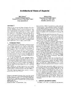
have developed the CPS architectural style [5] as a systemlevel unified representation for multi-domain models based on heterogeneous formalisms. A system’s base architecture is an annotated graph of components and connectors in which the components represent the principal computational and physical elements of the complete system’s run-time structure, the connectors represent pathways of communication and physical couplings between components, and annotations represent properties of the elements. An architectural view is another component-connector graph that represents a particular abstraction and refinement of various elements of the base architecture. Each model used in the system development is associated with an architectural view, based on the particular design perspective of the model. For example, a Simulink model created for feedback control analysis will be associated with a view defined in the control design perspective, while a process algebra model created to analyze system deadlock behavior will be associated with a software design perspective. In this context, welldefined mappings between a view and the base architecture can be used as the basis for identifying and managing the structural and semantic dependencies among the various verification models, and to evaluate mutually constraining design choices. Adherence to the component-connector structure of the base architecture assures that the structure of each architectural view (and hence each model) is consistent with the functional decomposition of the system as represented by the base architecture. We use the concept of graph morphisms to define a notion of structural view consistency [6] that supports the checking of the types of structural relationships that naturally arise in the construction of the verification models. Structural consistency allows us to check if each model adheres to the connectivity constraints between system elements, as defined in the base architecture. Information about the consistency of behaviors between models is captured by the notion of semantic view consistency, which checks whether each model has correct and consistent assumptions about the behavior of the rest of the system. As a first step towards addressing semantic consistency, we capture the semantic information shared between a model 𝑀𝑖 and the other views of the system with a set of static parameters 𝑃𝑖 that are associated with the corresponding architectural view. Parameters that are assigned to specific elements in the view can be checked for syntactic correctness, based on the structural mappings between the view and the base architecture. The semantic inter-dependencies between the views and the base architecture are represented by constraints on these parameters. As illustrated in Fig. 1, each view imports constraints on its parameters from the rest of the system, denoted by 𝐶𝑖𝑒𝑥𝑡 , the external constraints for model 𝑖. The base architecture is associated with the set of system-level parameters 𝑃0 , and the auxiliary constraints 𝐶𝑎𝑢𝑥 that represent the relation between 𝑃0 and each 𝑃𝑖 , as well as interdependencies between the various 𝑃𝑖 ’s. The remainder of the paper develops the formulation of conditions for consistency and correctness of verification
activities based on the relationships between the view-level and base architecture-level constraints on the parameters for each of the models and the system-level parameters. III. V ERIFICATION OF PARAMETERIZED M ODELS We begin by introducing definitions and notation for describing the use of parameterized models for verifying system properties. A parameter 𝑝 of a system is a realvalued static variable that affects the system behavior in some way. The valuation of a set of parameters 𝑃 is a function 𝑣 : 𝑃 → ℝ that associates each parameter with a value. 𝑉 (𝑃 ) denotes the set of all possible valuations of the parameters in 𝑃 . A constraint 𝐶(𝑃 ) over a set of parameters 𝑃 is an expression written in a constraint formalism 𝒞. For a given 𝑣 ∈ 𝑉 (𝑃 ), J𝐶(𝑃 )K𝑣 ∈ {T, F} denotes the evaluation of the constraint 𝐶(𝑃 ) at 𝑣 and J𝐶(𝑃 )K denotes the set of all valuations 𝑣 over 𝑃 for which J𝐶(𝑃 )K𝑣 = T. In this paper, we assume 𝒞 is the language of first-order real arithmetic (𝐹 𝑂𝐿ℝ ). Thus, validity and satisfiability of parameter constraints is decidable by Tarski’s quantifier elimination [20]. Conjunction of constraints 𝐶1 (𝑃 ) and 𝐶2 (𝑃 ), written 𝐶1 (𝑃 )∧𝐶2 (𝑃 ), is also a constraint whose corresponding parameter valuations are the intersection of the parameter valuations of the original constraints, i.e., J𝐶1 (𝑃 ) ∧ 𝐶2 (𝑃 )K = J𝐶1 (𝑃 )K ∩ J𝐶2 (𝑃 )K. Similarly, disjunction of constraints is a constraint whose corresponding parameter valuations are the union of the parameter valuations of the original constraints. We write 𝐶 ′ (𝑃 ) ⇒ 𝐶(𝑃 ) when J𝐶 ′ (𝑃 )K ⊆ J𝐶(𝑃 )K and 𝐶 ′ (𝑃 ) ≡ 𝐶(𝑃 ) when J𝐶 ′ (𝑃 )K = J𝐶(𝑃 )K. Given two sets of parameters 𝑃 and 𝑃 ′ , the projection of a constraint 𝐶(𝑃 ) onto 𝑃 ′ , written as 𝐶(𝑃 ) ↓𝑃 ′ , is the constraint over 𝑃 ′ defined by existential quantification of the parameters in 𝑃 ∖ 𝑃 ′ . Its valuations J𝐶(𝑃 ) ↓𝑃 ′ K are {𝑣 ′ ∈ 𝑉 (𝑃 ′ ) ∣ ∃𝑣 ∈ J𝐶(𝑃 )K : 𝑣 ′ (𝑝′ ) = 𝑣(𝑝′ ) ∀𝑝′ ∈ 𝑃 ′ ∩ 𝑃 }.
The constraint resulting from this existential quantification can be computed effectively for 𝐹 𝑂𝐿ℝ . Given a collection of constraints 𝐶1 (𝑃 ), . . . , 𝐶𝑛 (𝑃 ), it is straightforward to show that ( 𝑛 ) 𝑛 ⋀ ⋀ 𝐶𝑖 (𝑃 ) ↓𝑃 ′ ⇒ (𝐶𝑖 (𝑃 ) ↓𝑃 ′ ) . (1) 𝑖=1
𝑖=1
Let 𝑀 be a parameterized model with a set of parameters 𝑃 that is constructed in a particular modeling formalism ℳ. Let ℬ denote a behavioral domain, that is, ℬ is the set of all possible behaviors selected for defining the behavioral semantics of models in ℳ. Depending on the context, the behavioral domain could be, for example, event traces, pairs of continuous input-output signals, or hybrid trajectories. We define the semantics of a particular model by a mapping 𝜌ℳ : 𝒞 × ℳ → 2ℬ . Given a constraint 𝐶(𝑃 ) and model 𝑀 , 𝜌ℳ (𝐶(𝑃 ), 𝑀 ) denotes the set of all possible behaviors in ℬ associated with the model 𝑀 for all parameter valuations in J𝐶(𝑃 )K. We are interested in analyzing how constraints impact the sets of behaviors for models. Towards this end, we
System Models
…
Arch. Views
…
Base Arch.
Universal Model
Fig. 1.
Parameterized architectural views for heterogeneous system models.
will assume models are parameterized so that the set of possible behaviors grows or shrinks consistently with increasing or decreasing sets of valuations for constraints. This specification on the model parametrization is captured in the following definition. Definition 1 A model 𝑀 parameterized by a set of parameters 𝑃 in a formalism ℳ is said to be monotonic with respect to constraints if, for every constraint pair {𝐶(𝑃 ), 𝐶 ′ (𝑃 )},
𝐶(𝑃 ), 𝑀 ∣= 𝑆 when 𝜌ℳ (𝐶(𝑃 ), 𝑀 ) ⊆ 𝜌𝒮 (𝑆). Entailment specifies the relation between the model and a parameter constraint and the specification. For a given set of parameters 𝑃 and a specification 𝑆, building a model 𝑀 and constructing 𝐶(𝑃 ) such that 𝐶(𝑃 ), 𝑀 ∣= 𝑆 is a design task. On the other hand, checking whether 𝐶(𝑃 ), 𝑀 ∣= 𝑆 holds for given 𝐶(𝑃 ) and 𝑀 using a suitable analysis procedure is a verification task. The next section develops the concept of design and verification using heterogeneous models.
𝐶 ′ (𝑃 ) ⇒ 𝐶(𝑃 ) then 𝜌ℳ (𝐶 ′ (𝑃 ), 𝑀 ) ⊆ 𝜌ℳ (𝐶(𝑃 ), 𝑀 ). IV. H ETEROGENEOUS D ESIGN AND V ERIFICATION A specification 𝑆 is a condition written in a specification formalism 𝒮. 𝒮 can be, for example, various temporal logics, finite automata, Kripke structures, or a set of states to be avoided. The semantics for specifications is given by a mapping 𝜌𝒮 : 𝒮 → 2ℬ that associates a specification 𝑆 with a subset of the behaviors in ℬ for which the specification 𝑆 is satisfied. In this paper we consider only safety specifications. More specifically, we assume the specifications satisfy the following property. Definition 2 A specification formalism 𝒮 is said to be conjunctive with respect to a given semantic mapping 𝜌𝒮 if ∀ 𝑆 ′ , 𝑆 ′′ ∈ 𝒮, 𝜌𝒮 (𝑆 ′ ∧ 𝑆 ′′ ) = 𝜌𝒮 (𝑆 ′ ) ∩ 𝜌𝒮 (𝑆 ′′ ). In general, safety specifications are conjunctive and liveness specifications are not conjunctive. Given two specifications 𝑆 and 𝑆 ′ from a conjunctive formalism, we write 𝑆 ′ ⇒ 𝑆 when 𝜌𝒮 (𝑆 ′ ) ⊆ 𝜌𝒮 (𝑆). We consider design and verification procedures that aim to demonstrate that the behaviors of a model satisfy a given specification over a range of parameter valuations. We denote satisfaction of a given specification by entailment, namely,
We return to the multi-model setting described in Sec. II using the formal framework for modeling and verification introduced in the previous section. Suppose one wants to design a system with parameters 𝑃0 that satisfies the specification 𝑆0 for the range of parameter valuations represented by a constraint 𝐶0 (𝑃0 ). If there existed a universal modeling formalism ℳ0 that could model everything needed for the system design, a model 𝑀0 of the whole system could be constructed and an appropriate verification procedure could be applied to demonstrate 𝐶0 (𝑃0 ), 𝑀0 ∣= 𝑆0 . In reality, there is no such modeling formalism that can capture all the aspects of a complex cyber-physical system, including the physical dynamics, software, hardware, control, scheduling, communication protocols, etc. Even if there were a such a modeling formalism, building a detailed universal model 𝑀0 would be impractical and doing any kind of verification with the complexity of this grand universal model would be even more hopelessly impractical, if not impossible. Alternatively, rather than designing a complete system at once, a separation of concerns approach is used to design and analyze different aspects of the system using a variety
of models, each suited to a particular type of problem. To describe this approach formally, let ℳ𝑖 , 𝑖 = 1, . . . , 𝑛 denote the various modeling formalisms used for the heterogeneous design, and let 𝑀𝑖 ∈ ℳ𝑖 be the specific models that are constructed. In the process of decomposing the system design task into several smaller ones pertaining to the particular design tasks, model-level constraints 𝐶𝑖 (𝑃𝑖 ) are introduced using sets of parameters 𝑃𝑖 . To simplify the notation, we will use 𝐶𝑖 to denote 𝐶𝑖 (𝑃𝑖 ) in the following. These modelspecific parameters, such as controller gains in the control perspective, are not necessarily in the set of original systemlevel parameters 𝑃0 , but there are relationships between the various sets of parameters and the original system constraints impose constraints on the parameters in the various models. We let 𝐶𝑎𝑢𝑥 (𝑃 ) denote the auxiliary constraints ∪𝑛 that capture these dependencies over the parameters 𝑃 = 𝑗=0 𝑃𝑗 , which is the set of all parameters being used, including the original parameters 𝑃0 . Without loss of generality we assume the sets 𝑃𝑗 , 𝑗 = 0, 1, . . . , 𝑛 are disjoint. We also assume the auxiliary constraints do not impose a restriction on the original constraints, that is, (𝐶0 ∧ 𝐶𝑎𝑢𝑥 ) ↓𝑃0 = 𝐶0 .
(2)
Specifications 𝑆𝑖 are also introduced for each of the models. Given the individual models 𝑀𝑖 and the modellevel constraints 𝐶𝑖 and specifications 𝑆𝑖 for 𝑖 = 1, . . . , 𝑛, we then invoke analysis procedures to determine whether 𝐶𝑖 , 𝑀𝑖 ∣= 𝑆𝑖 . Figure 1 illustrates the overall decomposition of the design and verification problem. The hope is that the demonstration of entailment for each of the individual models will somehow guarantee that 𝐶0 , 𝑀0 ∣= 𝑆0 . In the following, we develop conditions under which this will be true. Definition 3 A set of specifications 𝑆1 , . . . , 𝑆𝑛 is said to satisfy specification coverage with respect to the original system (safety) specification 𝑆0 if ( 𝑛 ) ⋀ 𝑆𝑖 ⇒ 𝑆0 . 𝑖=1
This definition of coverage for the specifications is similar to the notion of requirements traceability: it is necessary to show that the requirements that are actually verified (𝑆𝑖 , 𝑖 = 1, . . . , 𝑛) are in fact sufficient to imply the original requirements. It is also necessary to demonstrate that the design has been verified for 𝐶0 , which specifies the full range of parameters 𝑃0 for which the specification 𝑆0 must hold. This is captured in the following definition that relates the parameter constraints in the models to the constraints on the original parameters. Definition 4 A set of constraints 𝐶1 , . . . , 𝐶𝑛 is said to satisfy constraint coverage with respect to the original system constraints 𝐶0 if ( ) 𝑛 ⋀ 𝐶0 ⇒ 𝐶𝑎𝑢𝑥 ∧ 𝐶𝑖 ↓𝑃0 . 𝑖=1
The notion of constraint coverage defined above requires that the set of constraints for the models over-approximates the original constraints when they are projected into the original parameter set through the auxiliary constraints. Finally, it is necessary to assure that the behaviors modeled by the individual models indeed cover the behaviors of interest in the original model. This requirement needs to be satisfied by the way in which the models are constructed. In particular, for the purposes of verification, it is necessary that the models overapproximate the behaviors of the actual system characterized by the system model 𝑀0 in the universal modeling framework ℳ0 . This is the concept of abstraction for heterogeneous models. Definition 5 A model 𝑀𝑖 in a modeling formalism ℳ𝑖 is said to be an abstraction of a model 𝑀0 in the modeling framework ℳ0 if for any constraints 𝐶𝑖 𝜌ℳ0 ([𝐶𝑎𝑢𝑥 ∧ 𝐶𝑖 ] ↓𝑃0 , 𝑀0 ) ⊆ 𝜌ℳ𝑖 (𝐶𝑖 , 𝑀𝑖 ). Note that the definition of abstraction maps the constraints over 𝑃𝑖 into the constraints over 𝑃0 using the auxiliary constraints. In practice, the modeling framework ℳ0 and model 𝑀0 are not actually specified. Nevertheless, this describes the intuition behind the current informal practice of heterogeneous design and verification. The definitions above provide conditions under which verification of the specifications for the individual models will imply satisfaction of the original specifications. Proposition 1 Given a model 𝑀0 in a modeling formalism ℳ0 with constraints 𝐶0 over parameters 𝑃0 and (safety) specification 𝑆0 , and a set of models 𝑀𝑖 constructed using modeling formalisms ℳ𝑖 with constraints 𝐶𝑖 over parameters 𝑃𝑖 and (safety) specifications 𝑆𝑖 for 𝑖 = 1, . . . , 𝑛. If i. constraints 𝐶𝑖 (𝑖 = 1, . . . , 𝑛) cover 𝐶0 , ii. model 𝑀𝑖 is an abstraction of 𝑀0 for each 𝑖 = 1, . . . , 𝑛 iii. specifications 𝑆𝑖 (𝑖 = 1, . . . , 𝑛) cover 𝑆0 , and iv. 𝐶𝑖 , 𝑀𝑖 ∣= 𝑆𝑖 for each 𝑖 = 1, . . . , 𝑛 then 𝐶0 , 𝑀0 ∣= 𝑆0 . Proof: In the following all conjunctions and intersections are over 𝑖 = 1, . . . , 𝑛. We first note that constraint coverage implies ⋀ ⋀ 𝐶𝑜 ⇒ ( 𝐶𝑖 ∧ 𝐶𝑎𝑢𝑥 ) ↓𝑃0 ⇒ (𝐶𝑎𝑢𝑥 ∧ 𝐶𝑖 ) ↓𝑃0 . 𝑖
𝑖
Therefore, monotonicity implies ⋀ 𝜌ℳ (𝐶0 , 𝑀0 ) ⊆ 𝜌ℳ ( (𝐶𝑎𝑢𝑥 ∧ 𝐶𝑖 ) ↓𝑃0 , 𝑀0 ) 𝑖
(monotonicity) ⊆
∩
𝜌ℳ ((𝐶𝑎𝑢𝑥 ∧ 𝐶𝑖 ) ↓𝑃0 , 𝑀0 )
𝑖
(abstraction) ⊆
∩
𝜌ℳ𝑖 (𝐶𝑖 , 𝑀𝑖 )
𝑖
(since 𝐶𝑖 , 𝑀𝑖 ∣= 𝑆𝑖 ) ⊆
∩ 𝑖
(specification coverage) ⊆ 𝜌𝒮 (𝑆0 ). Therefore, 𝐶0 , 𝑀0 ∣= 𝑆0 .
Def. 2
𝜌𝒮 (𝑆𝑖 ) = 𝜌𝒮 (
⋀ 𝑖
𝑆𝑖 )
The conditions introduced in Proposition 1 pertain to how the heterogeneous models and specifications relate to the original constraints in the original parameter space 𝑃0 . To perform analysis and design in the individual modeling frameworks, conditions are needed in the parameter spaces for each of the models. The constraint 𝐶𝑖 for model 𝑖 should be chosen so that it is not more restrictive than the original system constraints projected into the parameters 𝑃𝑖 . This condition is stated in the following definition. Definition 6 Constraint 𝐶𝑖 for model 𝑖 is said to be originalconstraint consistent if 𝐶𝑖𝑒𝑥𝑡 := (𝐶0 ∧ 𝐶𝑎𝑢𝑥 ) ↓𝑃𝑖 ⇒ 𝐶𝑖 . Lemma 1 If 𝐶𝑖 is original-constraint consistent, then (𝐶0 ∧ 𝐶𝑎𝑢𝑥 ) ↓𝑃𝑖 ⇒ (𝐶𝑖 ∧ 𝐶𝑎𝑢𝑥 ) ↓𝑃𝑖 . Proof: Consider any 𝑣𝑖′ ∈ J(𝐶0 ∧ 𝐶𝑎𝑢𝑥 ) ↓𝑃𝑖 K. Then ∈ J𝐶𝑎𝑢𝑥 ↓𝑃𝑖 K (note: 𝐶0 constrains only parameters 𝑃0 , which are disjoint from 𝑃𝑖 ). From the definition of originalconstraint consistent, 𝑣𝑖′ ∈ J(𝐶0 ∧ 𝐶𝑎𝑢𝑥 ) ↓𝑃𝑖 K also implies 𝑣𝑖′ ∈ J𝐶𝑖 K, which in turn implies 𝑣𝑖′ ∈ J(𝐶𝑖 ∧ 𝐶𝑎𝑢𝑥 ) ↓𝑃𝑖 K. The following proposition states the conditions for the constraints in the parameter spaces for each modeling frameworks that will guarantee that the original specifications are satisfied. 𝑣𝑖′
Proposition 2 Under the assumptions of Prop. 1 except that condition i. on the constraint coverage is replaced with i. 𝐶𝑖 is original-constraint consistent, we can still conclude 𝐶0 , 𝑀0 ∣= 𝑆0 . Proof: By Prop. 1, it is sufficient to show that constraints 𝐶𝑖 cover 𝐶0 . That is, we want to show ⋀ 𝐶0 ⇒ ( 𝐶𝑖 ∧ 𝐶𝑎𝑢𝑥 ) ↓𝑃0 . (3) 𝑖
Suppose (3) is not true, i.e., suppose there exists some 𝑣0′ ∈ 𝑉 (𝑃0 ) such that J𝐶0 K𝑣0′ = T but ⋀ J( 𝑖 𝐶𝑖 ∧ 𝐶𝑎𝑢𝑥 ) ↓𝑃0 K𝑣0′ = F. This implies ⋀ J 𝐶𝑖 ∧ 𝐶𝑎𝑢𝑥 K𝑣0′ ,⃗𝑣 = F
∀ ⃗𝑣 ∈
∏
𝑖
𝑉 (𝑃𝑖 ).
(4)
𝑖
From Lemma 1 and (4), J𝐶0 ∧ 𝐶𝑎𝑢𝑥 K𝑣0′ ,⃗𝑣 = F
∀ ⃗𝑣 ∈
∏
𝑉 (𝑃𝑖 ),
𝑖
which in turn implies J(𝐶0 ∧ 𝐶𝑎𝑢𝑥 ) ↓𝑃0 K𝑣0′ = F. This implies from (2) that J𝐶0 K𝑣0′ = F, which contradicts the initial assumption.
V. E XAMPLE We consider a platoon with two cars driving in a single lane, and communicating over an 802.11p inter-vehicular wireless network. The leader car 𝑙 sends its position and velocity to the follower car 𝑓 over the network. The position, velocity, and acceleration of 𝑙 are 𝑥𝑙 , 𝑣𝑙 , and 𝑎𝑙 respectively (and similarly for follower 𝑓 ). The follower has a controller that is required to maintain a specified distance of 𝑑𝑠𝑒𝑡 from the leader. The communication delay of the network, 𝑇𝑐 , is a function of the inter-vehicle distance 𝑑. If 𝑑 goes beyond 𝑑𝑚𝑎𝑥 , the network connectivity is lost, and the twocar platoon can no longer be maintained. ¯ denote the lower and upper bounds, respecLet 𝑥 and 𝑥 tively, on a parameter 𝑥. The system-level parameters and constraints are ¯𝑓 , 𝑎𝑓 , 𝑣¯𝑙 , 𝑣 𝑙 , 𝑣¯𝑓 , 𝑣 𝑓 𝑃0 : 𝑎 ¯𝑙 , 𝑎𝑙 , 𝑎 𝐶0 : Specific values for all parameters in 𝑃0 The system-level specification 𝑆0 for a safe platoon formation is given as 𝑆0 := (𝑥𝑙 − 𝑥𝑓 > 0) ∧ (𝑥𝑙 − 𝑥𝑓 ≤ 𝑑𝑚𝑎𝑥 ), which asserts the two cars never collide and are never more than 𝑑𝑚𝑎𝑥 meters apart. We consider three heterogeneous views for the two-car platoon. View 1 is a formal verification view associated with model 𝑀1 created in the KeYmaera tool [17]. 𝑀1 is a very general model that identifies an envelope of behaviors for any sampled-data control algorithm for car 𝑓 that will ensure that 𝑆0 is valid. This model assumes the acceleration and braking of both cars are bounded by 𝐴 and 𝐵, respectively. There is also an assumption that the minimum velocity of each car is non-negative, and that the total delay 𝜀 in the system (communication+sampling+reaction delay) is bounded. The representation of the controller in 𝑀1 is simple. If the controller determines that it is safe for the car to accelerate, any acceleration or braking within the bounded limits is allowed; however, if it determines that the system state is on the boundary of the set of safe states, the car must brake with its full braking force. The controller uses the following constraint to determine whether the car can accelerate safely up to time 𝜀, the maximum delay until the next sample occurs: ( )( ) 𝑣𝑓2 𝑣𝑙2 𝐴 𝐴 2 𝑥𝑙 > 𝑥𝑓 + − + +1 𝜀 + 𝑣𝑓 𝜀 2𝐵 2𝐵 𝐵 2 If this constraint holds for current sensor readings of position and velocity, then car 𝑙 will still be safely in front of 𝑓 until the controller receives sensor data and can react again (i.e., after they drive for up to 𝜀 time), no matter how 𝑙 and 𝑓 accelerate or brake. For a more detailed description of this model and its verification, see [15]. Verifying the correctness of this generic model makes it possible to verify a wide range of controllers by simply assuring that specific controllers have an input-output map that is assured to apply maximum braking on the boundary of the region of safe states. In this example, this condition is
used in View 1 to verify the correctness of a sampled-data PID controller design in View 2. The procedure described above can also be used to verify that the distance between the cars does not exceed 𝑑𝑚𝑎𝑥 . View 2 is a control design view that is associated with model 𝑀2 created in Simulink. 𝑀2 is a sampled-data PID controller for the follower car designed to keep 𝑓 around 𝑑𝑠𝑒𝑡 meters of the leader. The control design takes the network communication delay 𝑇𝑐 into account. The controller has a sampling period 𝑇𝑠 and the set 𝐾 of PID gains is given by {𝐾𝑝 , 𝐾𝑖 , 𝐾𝑑 }. Additionally, we assume bounds on the velocity and acceleration of the two cars in 𝑀2 . The constraints on 𝑣𝑙 and 𝑣𝑓 indicate the operating regime over which we want to verify the correctness of our controller. The idea is that the real car controller would switch into the PID mode only when the platoon is moving at some nominal speed, and there are other things that are done outside of this regime. Our interest is verifying that if the system remains in this regime where the PID controller operates indefinitely, there will be no collisions. Since the Simulink view can only be used to run simulations, the parameters from the control design are passed to View 1 through 𝐶𝑎𝑢𝑥 for formal verification. This includes the distance set point, 𝑑𝑠𝑒𝑡 , which is a design parameter selected in the control design view. View 3 is a communication perspective. The associated model 𝑀3 is created in the ns-2 network simulator [16] to calculate 𝑇𝑐 for the specified 𝑑𝑚𝑎𝑥 . The 𝑇𝑐 derived from the communication view is a design constraint that must be adhered to in 𝑉2 , and is also used in View 1 via 𝐶𝑎𝑢𝑥 as one of the elements in the composition of 𝜀. To summarize, the parameters for the three views are given by 𝑃1
:= 𝑃0 ∪ {𝜀, 𝐾, 𝑑𝑠𝑒𝑡 }
𝑃2
:= 𝑃0 ∪ {𝑇𝑐 , 𝑇𝑠 , 𝐾, 𝑑𝑠𝑒𝑡 }
𝑃3
:= {𝑇𝑐 }
The auxiliary constraint 𝐶𝑎𝑢𝑥 contains the set of equality constraints between the same parameters in the three views, as well as the constraint 𝜀 = 𝑇𝑠 + 𝑇𝑐 that bounds the total system delay 𝜀. The specifications for the three views are given by 𝑆1 ≡ 𝑆0 , and 𝑆2 = 𝑆3 = T. In other words, the verification of the system specifications is performed in View 1 using values from determined by the designs in Views 2 and 3. We have verified 𝐶1 , 𝑀1 ∣= 𝑆1 in KeYmaera. If the designer views the heterogeneous models 𝑀2 and 𝑀3 to be abstractions of sampled-data PID controllers, and all models, constraints, and specifications meet the requirements in Proposition 2, it can be concluded that 𝐶0 , 𝑀0 ∣= 𝑆0 . Note that this last statement is a decision that needs to be made in the context of the actual application. As noted in Sec. IV, the model underlying the base architecture is not actually constructed. Rather, engineering judgement is used to determine whether or not the set of models is acceptable as a collection of abstractions for the real system. This simple example illustrates the application of this approach
for only a small part of the specifications that would be addressed for a real system. The value of the approach lies in the discipline of identifying the relationships between the models, parameters and constraints formally. VI. D ISCUSSION This paper presents a new approach to using heterogeneous models for design and verification of complex cyberphysical systems based on the concept of architectural views where syntactical and semantical consistency relationships between the models are identified explicitly. Heterogenous design and verification activities are standard engineering practice, because different questions typically need different models, modeling formalisms, and tools. In current practice, the relationship among the heterogeneous models remains informal at best. We have introduced parameter specification and constraint consistency as a first step in developing lightweight tools for assuring some degree of correctness in the application of multiple modeling formalisms. We have shown how heterogeneous models may be used together to reason about the safety of cyber-physical systems. We are currently implementing support for analyzing structural consistency between architectural views in the AcmeStudio architectural design environment [6]. Next steps will be to add support for the specification and evaluation of parameter consistency, and to extend the approach developed in this paper to allow dynamic assumptions, e.g., by allowing automata, LHA, temporal logic formulas, etc., to capture the behavioral assumptions and inter-model dependencies in models used in multi-domain model-based design and verification. R EFERENCES [1] SysML. http://www.sysml.org/. [2] R. Passerone A. Pinto, L. P. Carloni and A. Sangiovanni-Vincentelli. Interchange semantics for hybrid system models. In Proc. of 5th MATHMOD, 2006. [3] F. Balarin, Y. Watanabe, H. Hsieh, L. Lavagno, C. Passerone, and A. Sangiovanni-Vincentelli. Metropolis: an integrated electronic system design environment. Computer, 36(4):45–52, april 2003. [4] S. S. Bhattacharyya, E. Cheong, and I. Davis. Ptolemy II heterogeneous concurrent modeling and design in java. Technical report, University of California, Berkeley, 2003. [5] A. Bhave, D. Garlan, B.H. Krogh, A. Rajhans, and B.Schmerl. Augmenting software architectures with physical components. In Proc. of the Embedded Real Time Software and Systems Conf. (ERTS2 2010), 19-21 May 2010. [6] A. Bhave, B. H. Krogh, D. Garlan, and B. Schmerl. View consistency in architectures for cyber-physical systems. In Proc. of Second International Conference on Cyber-Physical Systems, ICCPS, 2011. [7] K. Chen, J. Sztipanovits, and S. Abdelwahed. Toward a semantic anchoring infrastructure for domain-specific modeling languages. In 5th ACM InternationalConference on Embedded Software, volume September, 2005. [8] P. Clements, F. Bachmann, L. Bass, D. Garlan, J. Ivers, R. Little, R. Nord, and J. Stafford. Documenting Software Architectures: Views and Beyond. Addison-Wesley, 2002. [9] James Davis. GME: The Generic Modeling Environment. In Companion of the 18th annual ACM SIGPLAN conference on Object-oriented programming, systems, languages, and applications, OOPSLA ’03, New York, NY, USA, 2003. ACM.
[10] Zonghua Gu, S. Kodase, Shige Wang, and K.G. Shin. A modelbased approach to system-level dependency and real-time analysis of embedded software. In Proceedings of the 9th IEEE Real-Time and Embedded Technology and Applications Symposium, 2003., pages 78 – 85, May 2003. [11] T.A. Johnson, C. J. J. Paredis, and R. M. Burkhart. Integrating models and simulations of continuous dynamics into sysml. In 6th International Modelica Conference, pages 135–145. Modelica Association, 2008. [12] Rajesh Kumar, Bruce H. Krogh, and Peter Feiler. An ontologybased approach to heterogeneous verification of embedded control systems. In Manfred Morari and Lothar Thiele, editors, Hybrid Systems: Computation and Control, volume 3414 of Lecture Notes in Computer Science, pages 370–385. Springer Berlin / Heidelberg, 2005. [13] Akos Ledeczi, James Davis, Sandeep Neema, and Aditya Agrawal. Modeling methodology for integrated simulation of embedded systems. ACM Trans. Model. Comput. Simul., 13:82–103, January 2003. [14] J.M. Leung, T. Mandl, E.A. Lee, E. Latronico, C. Shelton, S. Tripakis, and B. Lickly. Scalable semantic annotation using lattice-based ontologies. In 12th International Conference on Model Driven Engineering Languages and Systems, pages 393–407. ACM/IEEE, October 2009. [15] Sarah M. Loos, Andr´e Platzer, and Ligia Nistor. Adaptive cruise control: Hybrid, distributed, and now formally verified. In Michael Butler and Wolfram Schulte, editors, FM, LNCS. Springer, 2011. [16] T Murray, M. Cojocari, and Huirong Fu. Measuring the performance of ieee 802.11p using ns-2 simulator for vehicular networks. In IEEE Conf. on Electro Information Technology, pages 498–503, 2008. [17] Andr´e Platzer. Logical Analysis of Hybrid Systems: Proving Theorems for Complex Dynamics. Springer, Heidelberg, 2010. [18] J. Porter, P. Volgyesi, N.Kottenstette, H.Nine, G.Karsai, and J. Sztipanovits. An experimental model-based rapid prototyping environment for high-confidence embedded software. In RSP ’09: Proceedings of the 2009 IEEE/IFIP International Symposium on Rapid System Prototyping, pages 3–10, Washington, DC, USA, 2009. IEEE Computer Society. [19] A. Rajhans, S-W Cheng, B. Schmerl, D. Garlan, B. H. Krogh, C. Agbi, and A. Bhave. An architectural approach to the design and analysis of cyber-physical systems. In Third International Workshop on MultiParadigm Modeling, Denver, Oct 2009. [20] Alfred Tarski. A Decision Method for Elementary Algebra and Geometry. University of California Press, Berkeley, 2nd edition, 1951. [21] Hans L. M. Vangheluwe. DEVS as a common denominator for multiformalism hybrid systems modeling. In Proceedings of the 2000 IEEE International Symposium on Computer-Aided Control System Design, Anchorage, Alaska, USA, 2007.