(2) IBM T. J. Watson Research Center, email {cschuste, kwark}@us.ibm.com ... On the other hand frequency domain characterization by means of S-parameter ...
Using S-Parameters Successfully in Time Domain Link Simulations Dierk Kallerl, Christian Schuster2, Young Kwark2, Dulce Altabella3, Bao Truong3, Zhaoqing Chen3, Anand Haridass3, Erich Klink' (1) IBM Deutschland Entwicklung GmbH, Schoenaicher Str. 220, Boeblingen, Germany Tel.: +49-7031-16-2330, Fax: +49-7031-16-2042, email {dkaller, eklink}@de.ibm.com (2) IBM T. J. Watson Research Center, email {cschuste, kwark}@us.ibm.com (3) IBM Server & Technology Group, email {adulce, bao, zhaoqing, anandh}@us.ibm.com Abstract Eye diagrams measured or simulated in time domain are widely used for characterization of electrical links. On the other hand frequency domain characterization by means of S-parameter measurements is gaining considerable ground. For direct comparison of eye diagrams, S-parameters have to be converted into time domain responses. In this paper we will discuss criteria for the evaluation of the "goodness" of S-parameters for use in time domain link simulations.
1. Introduction Electrical link compliance testing is usually done in the time domain. Both eye mask and bit error rate tests provide necessary information to make a pass/fail decision. Most link specifications are also provided in the time domain. The test equipment is widely available and digital engineers are familiar with its operation and the underlying concepts. On the other hand, frequency domain measurements, especially S-parameter measurements using vector network analyzers, have been favored by RF engineers for a considerable time. They provide coverage beyond 100 GHz and offer signal-to-noise ratios of 80 dB or more. S-parameters offer a portable and universal description of the device under test and allow further postprocessing. In addition, electromagnetic simulation tools routinely produce S-parameters that can be directly compared to measurement results. Due to these capabilities the frequency domain approach has made inroads into electrical link analysis. For direct comparison to time domain data like eye diagrams and bit error rates S-parameters have to be transformed either by inverse Fourier transform [Ulr86] or rational function approximation and equivalent circuit generation [GeeO4] In either case the quality of the S-parameters is of crucial importance and needs to be checked against a series of criteria.
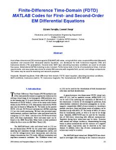
2. What Can Go Wrong This section gives a real-world example of what can go wrong with S-parameter based time domain link simulations. The link under test contained two passes through a connector, typical for a backplane application. A full-wave electromagnetic field. simulator was used to generate S-parameters of the connector and the 7_:-:.....-.X.adjacent vias in the printed circuit board up to a frequency of 10 GHz. The S~~~~~~~~~~~~~~~~~.. .. .... .... .... .. ...... .........parameters were converted to an equivalent circuit model for SPICE 5 6~~~~~~~~~~~..... ............... simulation and concatenated with transmission line models. Transient 4 '''t-;'' 'e 't '-' .
s......---
..... .......
3
__-------------_----Sal1 lr
---
-----------
_2-----------sti---
]
stability (Figure 1).
simulations showed immediately problems with convergence and numerical
, >!..> A passivity study of the connector model showed singular values greater than . .-_-1 at frequencies higher than 10 GHz - a clear sign of non-passivity even if ~~~the original S-parameters displayed no passivity violations. Coincidently, the frequency of the highest singular value (at 11.7 GHz) corresponded exactly ----------------______ ---- ----------------- t e rn i g f e u n y s o n i i u e 3 n a s c n te p h o e _____ -----t------*----------------_____ - - r_____to - - - -----------------o the ringing frequency shown in Figure 3. In a second attempt the model was fitted to the S-parameters using passivity enforcement. This eliminated 0 10 20 30 40 I fife immediately the problems with convergence and numerical stability, timns) Figure 1: Time domain simulation for however, the results of the SPICE simulations still had issues. Although the a link with a non-passive model. input bit stream was balanced and no offset could be introduced by the ideal I/O circuits, the eye diagram was not centered around VDD/2 and this crossover shifts results in eye opening losses as great as 10%. Ultimately, the frequency content of the S-parameter models was deemed insufficient and increased from 10 GHz to 20 GHz. Similarly, the accuracy parameter was increased from 20 dB to 40 dB. With models based on these new extraction parameters, the time domain simulations behaved better and had little to no crossover shifts.
>7= 10 GHz), the group delay of the rational function approximation model goes down to zero which is - physically speaking - nonsense. Just like the original S-parameter the rational function approximation will show non-causal behavior (ripples before the minimum signal delay time) in a transient simulation that has frequency content above 10 GHz.
For passive channels without non-reciprocal elements (like ferrites) the S-parameters show reciprocity Reciprocity [Poz98], i.e. symmetry according to: Sij = Sji where index i is unequal toj. Reciprocity offers an easy test of S-parameter quality. In our measurements reciprocity was typically preserved within 0.05 dB and 0.1 degree for frequencies lower than 5 GHz. With increasing frequency / decreasing power levels the reciprocity is less accurate. Reference [SchO5] reports reciprocity for a board measurement within +/- 0.25 dB and +/- 2 degree.
The accuracy of S-parameter measurements is mostly determined by the quality of the calibration Accuracy / Noise and the contact to the devices under test. In the experience of the authors a calibration with GS microprobes on a calibration substrate could be used for channel measurements up to 20-40 GHz over a period of several days. In general it is advisable to check the calibration quality on a regular basis before, during, and after taking measurements. The noise floor of VNAs can be made as low as -100 dB by using a low IF bandwidth (5 300 Hz) or averaging (> 16). It was seen that noise was never an issue in backplane channel characterization. If data appear to be "noisy" a second measurement can quickly reveal if the noise is real or due to e.g. contact problems.
4. Conclusions and Outlook In this paper we addressed issues related to S-parameter based link simulations in time domain and we proposed a series of Sparameter quality criteria. High quality is of crucial importance when comparing e.g. S-parameter based and directly measured eye diagrams. Due to space constraints related issues like the set up of time/frequency domain equivalent measurements could not be discussed but will be addressed in future publications.
Acknowledgments The authors would like to thank Troy Beukema from IBM Research, NY, and Prof. S. Grivet-Talocia from the Politecnio di Torino, Italy, for many insightful discussions and help with generating S-parameter based eye diagrams.
References [Har78] [Ulr86]
[Tes92] [Poz98]
[Per98]
[Gus0l]
[GriO4] [GeeO4]
[PupO5] [SchO5]
F. Harris, "On the Use of Windows for Harmonic Analysis with the Discrete Fourier Transform", Proceedings of the IEEE, vol. 66, no. 1, pp. 51-83, January 1978. B. Ulriksson, "Conversion of Frequency-Domain Data to the Time Domain", Proceedings of the IEEE, vol. 74, no. 1, pp. 74-77, January 1986. F. M. Tesche, "On the Use of the Hilbert Transform for Processing Measured CW Data", IEEE Transactions on Electromagnetic Compatibility, vol. 34, no. 3, pp. 259-266, August 1992. D. M. Pozar, "Microwave Engineering, Second Edition", John Wiley, New York, 1998. P. A. Perry, T. J. Brazil, "Forcing Causality on S-Parameter Data Using the Hilbert Transform", IEEE Microwave and Guided Wave Letters, vol. 8, no. 11, November 1998. B. Gustavsen, A. Semlyen, "Enforcing Passivity for Admittance Matrices Approximated by Rational Functions", IEEE Transactions on Power Systems, vol. 16, no. 1, pp. 97-104, February 2001. S. Grivet-Talocia, "Passivity Enforcement via Perturbation of Hamiltonian Matrices", IEEE Transaction on Circuits and Systems - I: Regular Papers, vol. 51, no. 9, pp. 1755-1769, September 2004. J. De Geest, S. Sercu, C. Clewell, J. Nadolny, "Making S-Parameter Data Suitable for SPICE Modeling", IEC DesignCon 2004, January 2004. P. J. Pupalaikis, E. Yudin, "Eye Pattern in Scopes", IEC DesignCon 2005, January 2005. R. Schaefer, "Discussing the Limitations and Accuracies of Time and Frequency Domain Analysis of Physical Layer Devices", IEC DesignCon 2005, January 2005.
98