Using Soft Processors for Component Design in SOC: A Case-Study of Timers M. Ortiz, M. Brox, F. Quiles, A. Gersnoviez, C. Moreno, M. Montijano Universidad de Córdoba. Departamento de Arquitectura de Computadores, Electrónica y Tecnología Electrónica Edificio Leonardo Da Vinci. Campus Universitario de Rabanales, 14071-Córdoba, Spain
[email protected] Abstract—System on Chip (SOC) could be considered as a very useful alternative in the design of real-time systems, especially due to the possibility of integrating several processors in just one FPGA. This strategy enables the use of soft processors to design the system’s components, which have traditionally been developed by hardware. In this paper we study a HW/SW codesign of a timer pool for its use in SOC, which is constructed by a Picoblaze soft processor. Our approach offers a novel alternative among hardware and software timers that increases the overall system performance, and achieves a higher precision than software timers with a considerable reduction in cost and area occupied. I. INTRODUCTION Timers play an important role in any scheduler for realtime systems. In this case, the scheduler must be carefully designed in order to have few overheads in the system, especially in timer management. Some authors implement the scheduler in hardware to address the overhead [1, 2, 3]. On the other hand, applications related to periodic data acquisition, motor control, signal generation, pulse counting and loop timeout use a great number of timers. The use of soft processors can be an alternative in hardware-software co-design. This alternative is explored in [4] where three different scheduler implementations are investigated. A software implementation uses a processor to run the scheduler and the application tasks. A softwaresoftware implementation uses a processor to run the application tasks, and a co-processor to run the scheduler. In a hardware-software implementation, the scheduler is implemented directly in the hardware. Different timer resolutions are required depending on the application. When a low precision is required, a software solution is a good option. On the other hand, if a high precision is demanded, a hardware implementation is necessary. When a system is considered, it is analysed the number of hardware and software timers to implement depending on the cost and processing capacity respectively. Later on in
1-4244-2542-6/08/$20.00 ©2008 IEEE
this paper, we are going to perform a study of HW and SW timers showing a very interesting alternative, especially for SOC, by using a simple soft processor. II. HARDWARE TIMERS Hardware timers are timers implemented by hardware circuit logic. They are counters that work to a fixed frequency. They have a high precision and do not create an overhead for the processor. Implementing hardware timers is the most efficient way to achieve timers in a computing system. This is the most accurate option and the one that involves the lowest overhead in the system. However, the implementation cost and the area occupied on the FPGA is high. Theoretically the number of HW timers could be unlimited. However the occupied size on the FPGA, the power consumption and programming complexity impose some limitations in SOC. Because of this, it is not usual to implement a high number of hardware timers in systems. For instance, a circuit with sixteen autoload timers of sixteen bits implemented into a Xilinx Spartan-xc3s200 consumes 496 Slices of the FPGA, approximately 12% of the available resources, without including the external interface logic. III. SOFTWARE TIMERS Hardware timers are limited in a system. Because of this, it is necessary to use software timers for applications that require an unlimited number of timers. Software timers are a piece of code connected to the system clock interrupt. Each timer is represented by a data structure. A basic data structure is shown in Fig. 1. struct timer { int used; /* TRUE if in use */ TIME time; /* time left */ TIME period; /* time to wait */ int *event_timeout; /* set to TRUE at timeout */
} timers[MAX_TIMERS]; /* set of timers */ Fig. 1. Basic data structure of timer.
The system reserves memory for a fixed number of timers which will depend on the available memory. This memory limits the number of timers that can be defined. However, the number of software timers and the precision of these timers will strongly influence the processor efficiency, as we will see later. In order to connect to the periodic timer interrupt, a code, shown in Fig. 2, is used: / Interrupt handler for all timers objects in use { time is decreased; the count timer reaches zero { /if true load de initial count; event_timeout signalling; } } Fig. 2. Pseudoce of periodic timer interrupt All the systems present a clock that connects to an interrupt routine generating a basic timing. Software timers are implemented using the clock interrupt routine in order to decrease the associated variables for each time period. These variables are the software timers. Thus, the number of software timers can be considered unlimited if we only estimate the memory capacity. These timers are a good solution for non real-time systems and all general operating systems use this technique. However, software timers should be used carefully in hard real-time systems. Because this code runs periodically, by introducing an overhead into the system the computing time and precision will limit the number of timers. Certain hard real-time tasks demand precise timing of events but software timers driving for periodic interrupts only provide precision in the millisecond range. For instance, we obtain a computing time of 8.8 μs for a MicroBlaze processor [5] at 50 MHz and a number of sixteen timers. The overhead is low if the interrupt period is of 1ms. However, if the period decreases to 0.1ms, the overhead involves consumption of about 8.8 %. According to this idea if the number of timers increases to 100, the computing time would be 50 μs, which involves consumption of about 5 % for an interruption period of 1 ms. Therefore, by using a MicroBlaze processor and software timers, the use of periodic interrupt timers lower than 1 ms is not reasonable.
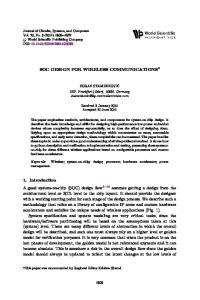
IV. HARDWARE SOFTWARE CODESIGN OF TIMERS The simplicity of integrating soft processors on FPGAs allows us to implement particular functions by using simple soft processors. The use of soft processors to carry out SOC components provides an efficient solution in terms of resources and cost. The soft processor solution is very attractive since its area size is low. In this paper, we present a timer pool by using a simple soft processor such as a PicoBlaze microcontroller processor [6] that occupies 192 logic cells, which represents just 5% of a Spartan-3 XC3S200 device. This system of timers presents advantages and drawbacks compared with hardware and software timers. The precision of HW/SW timers will be always lower than the precision obtained by using HW timers and it will depend on the response time of the system of timers. The minimum period of timers and the time to access the external bus will be different, depending on the soft processor frequency and the HW/SW partitioning that the designer has made. Timers are in charge of increasing the count, carrying out the autoload and attending to the main processor. An important point is the HW/SW partitioning of the system functions. According to this idea, all the non-timing crucial complex control functions will be executed by software. This decision is crucial since it affects the response time. For each particular case, a response time analysis of the system must be performed, considering it as a hard realtime system. For our study we have decided to minimize the necessary hardware in order to implement the timers. Therefore the tasks related to the increase of timers, the autoload and the timer initiation by the main processor, are going to be programmed. On the other hand the control operations of the timers such as overflow clearing and timer stopping are implemented by hardware. Fig. 3 shows a block diagram of our timer system with sixteen autoload timers of sixteen bits. The logic that performs the interface to the external bus has not been shown in order to simplify the diagram. The count value and timers load are stored in the 64-bytes scratchpad RAM PicoBlaze. The interface to the main processor is composed by a command register, an overflow register and a gate register. The pre-scaler is written by the main processor and produces the periodic interrupt for Picoblaze. The IRQ to the main processor is active and it is requested when overflow and gate bits are set for a particular timer.
OVERFLOW REGISTER
executed in PicoBlaze. The program is performed in assembler language.
IRQ
GATE REGISTER Only clear Microprocessor BUS or external BUS
COMAND REGISTER
IRQ IRQ ACK
READY CONTROL AND IRQ PICOBLAZE CONTROL
PRESCALER
Fig. 3.
PICOBLAZE
tick
Block diagram of HW/SW timers
The command register is a 32-bit register. Fig. 4 shows the meaning of the bits. The bits t3 to t0 represent one of the 16 timers. If a 16 or 8 bit external bus is used, the writing to the byte control timer (Byte 3) will start the timer with “initial count high and low” values. bit 7 ….... bit 0 unused Byte 4 gate x x x t3 t2 t1 t0 Byte 3 initial count high Byte 2 initial count low Byte 1 Fig. 4. Command register. The overflow and gate registers are set by PicoBlaze and cleared from the external bus. It is not possible to use PicoBlaze in order to clear these bits because the response time of PicoBlaze is high in comparison with the external bus. The main processor finishes the bus cycle before the register is cleared by PicoBlaze, and a new false interrupt occurs. The timers are started by setting the gate bit in the command register and PicoBlaze sets the gate register. The timers are stopped by clearing the gate bit in the gate register by the main processor. The logic ready and IRQ Picoblaze control are in charge of generating the interrupt for PicoBlaze and extending the external bus cycles, as we will see later. A. Soft processor code The main processor requests to Picoblaze to generate interrupts. Thus, the attention to the main processor has the highest priority. Fig. 5 shows the pseudocode, which is
/Main code while TRUE { wait tick; /trigger for all timers { disable interrupt; /critical section begin increment timerL; increment timerH; if overflow { set bit overflow register; load initial count timerL; load initial count timerH; } enable interrupt; /critical section end } } /Interrupt handler (ISR) read command register; if gate set /initialization timer { clear bit overflow register; load initial count timerL; load initial count timerH; } Fig. 5. Soft processor pseudocode. There are two tasks: the ISR (Interrupt Service Routine) and the main code that controls the timers. The ISR code loads the initial count of the timers and sets the gate bit. The main code waits for the tick and the timer count is increased. (All the SW timers in Picoblaze are running continuously). The gate register controls the activation of a specific timer. If increasing this produces an overflow in the timer, the overflow bit is set and an interrupt is received in the main processor. B. Response time analysis of HW/SW timers. The worst-case execution times at 50 MHz are 14 μs for the main code and 760 ns for the ISR code. The access to the 64-byte scratchpad RAM (timers) is shared from the ISR and the main code; therefore it will be necessary to perform mutual exclusion. In our case mutual exclusion will involve a blocking time of the interrupt. The maximum block time is 600 ns at 50 MHz. We can conclude that the worst-case execution time of a request from the main processor is the ISR execution time plus the block time. In our case, this execution time is 1.360 μs. The access time from the main processor is very low since the requests are registered. However a second access
would produce a larger bus cycle since it is not possible to attend a request while another is being attended. The response time to the main processor request has no influence on the access time if they are performed punctually. Since the purpose of our study is a hard real-time system, we must perform an analysis which allows us to find out a limit in the response time of the system. We are going to show how it is possible to find out a limit in the response time by performing the following approximations. We will consider that the tasks, the main code and the ISR code are periodic and the relative deadline of the task is equal to its period. The main code is obviously periodic but the ISR code is not. Although this involves a worst-case approximation, we are going to take the ISR as periodic. Then we can use a rate–monotonic algorithm and a very simple schedulability test, chosen because of their simplicity, despite neither being particularly accurate [7]. If we use a rate-monotonic algorithm for both ISR and main code tasks, the two tasks meet their deadlines if N
⎛ Ci ⎞
∑ ⎜⎝ T ⎟⎠ < N (2 i =1
i
1/ N
)
−1
(1)
V. CONCLUSIONS The use of soft processors in FPGAs facilitates the development of HW/SW co-design of parts of the system. The use of little soft processors simplifies the control logic design and reduces the area size. In particular, the timer pool proposed uses a smaller FPGA area and provides slightly better accuracy than software-only timers. A wellknown soft processor which has associated tools that minimize the development time has been used. Following the proposed procedure, more timers can easily be implemented with other characteristics. Two PicoBlaze could be used in order to have thirty two timers using the same memory block for the program. If a higher number of timers is required, ram memory can be added to PicoBlaze in order to store timers together with the initial count. Another advantage for the system on chip multiprocessor (MPSOC) is the possibility of obtaining coprocessors whose code is loaded in the execution time of the main processor. The analysis of these systems, which have been performed with soft processors, must be studied as a hard real-time system and therefore it is possible to design arbiters/schedulers in this way.
where N is the number of tasks, C is the worst–case computation time for the task and T is the task period. For our case:
C main C ISR + < 0.828 Tmain T ISR
VI. REFERENCES [1]
P. Koout, Ganesh, and B. Jacob.”Hardware support for real-time operating system”. Proceedings of the First International conference on Hardware/Software Codesign and System Synthesis (CODESISSS), Newport Beach, California, 2003.
[2]
V. Mooney III. Hardware/software partitioning of operating systems. In Design, Automation and Test in Europe Conference (DATE’03), 2003, pp. 338–339.
[3]
D. Andrews, D. Niehaus, and P. Ashenden. Programming models for hybrid CPU/FPGA chips. IEEE Computer, v..37(1), 2004, pp.118–120.
[4]
M. Vetromille, L. Ost, C. Marcon, C. Reif, and F. Hessel. RTOS Scheduler Implementation in Hardware and Software for Real Time Applications. Proceedings of the Seventeenth IEEE International Workshop on Rapid System Prototyping (RSP’06), 2006
[5]
Xilinx Company, “MicroBlaze User Guides”, http://www.xilinx.com/products/design_resources/proc_central/ microblaze.htm
[6]
Xilinx Company, “PicoBlaze User Guides”, http://www.xilinx.com/ipcenter/processor_central/picoblaze/picobla ze_user_resources.htm
[7]
Liu and J. Layland,” Scheduling Algorithms for Multiprogramming in a Hard Real-time Environment”, Journal of the ACM, 20(1):46-61, Jan. 1973.
(2)
This equation is not ideal for our case, but it allows us to have an analytic equation for response time. With the purpose that the main code meets its deadline, the time that must be reserved between accesses can be determined. For instance, for a case of sixteen timers with a precision of 100 μs (Tmain) at 50 MHz, a period between accesses of 1’725 μs must be guaranteed. The times between accesses to the HW/SW timers system can be guaranteed in the main processor program. However we can also have a little counter which extends the bus cycles to the system, acting as an arbiter/scheduler. In this way the arbiter/scheduler is very simple. This simple arbiter/scheduler is based on a very pessimistic approximation that reserves computing time of PicoBlaze for the increased timer operations. However this approach leads to a very simple arbiter/scheduler. This simple arbiter/scheduler is enough because the bus extensions are only produced when the timers are started.