Proceedings of the World Congress on Engineering 2009 Vol I WCE 2009, July 1 - 3, 2009, London, U.K.
Using Virtual I/O for CAN Bit Timing Conformance Tests1 I. Sheikh, M. Short, and K.F. Athaide.
Abstract— This paper will discuss the use of a new scheme to conduct conformance testing of the Controller Area Network (CAN) protocol implemented in a soft core, using Virtual I/O and integrated logic analyzers. Virtual I/O is particularly helpful in generating bit pattern’s on a CAN bus which are accurate to a single CAN bit time, as these patterns are generated using the same system clock rather than an external clock as is the case of a bench pattern generator. Based around simple off-the-shelf development boards, general purpose software code and the simple analysis tool Chipscope, the proposed method allows developers to verify the bit timing properties of a CAN soft core against the relevant ISO standards. Finally, we describe the use of a test bed in the verification of an open-source CAN soft core implementation. Index Terms—CAN, Conformance Testing, Chipscope VIO, Bit time, Soft Core
I. INTRODUCTION Conformance testing is an integral part of any protocol development, as it tests the behavior and capabilities of an implementation against the requirements set by a standard [1]. Controller Area Network (CAN) is a widely used protocol for distributed systems [2]. Many different CAN controllers (e.g. [3], [4]) are widely available in integrated circuit form; as such they cannot be modified, although in many cases a flexible implementation will be required for a given system implementation. In the context of the current paper, a CAN implementation was required for an ongoing project [5] which could be modified to add new features based, primarily on hardware implementation of CAN-based shared clock scheduler [6]. Hence, to make the desired changes a soft core solution was required and implemented on an FPGA and programmed in Verilog HDL [7]. FPGA’s provides full internal visibility using integrated logic analyzers ILA like Signal Tap [8] and Chipscope pro [9]. These tools provide small and efficient cores to debug not only I/O but also internal signals, and provide real time 1
Manuscript received March 23, 2009. This work is part of the PhD studies of Mr. Imran Sheikh and is supported by NWFP University of Engineering & Technology, Peshawar, Pakistan. I. Sheikh is with ESL, Engineering Department, University of Leicester, UK, LE1 7RH. (tel: +44-116-2522578; e-mail:
[email protected]). M. Short is a lecturer in Embedded Systems at the University of Leicester, UK. (tel: +44-116-2525052; e-mail:
[email protected]). K.F. Athaide is a PhD student at ESL. (e-mail:
[email protected]).
ISBN: 978-988-17012-5-1
in-system debugging features via JTAG. One other major feature which is provided by Chipscope is the capability for Virtual Input Output (VIO), which is implemented as a customizable core and can stimulate a design using pulse trains which can be either synchronous or asynchronous to the system clock. ISO has developed a standard CAN Conformance testing Document [10] and for any device to be declared CAN conformant, evidence is required that shows the testing procedures outlined in the standard have been performed and passed without problem. The ISO document not only specifies different types of tests that must be performed for conformance testing, but also specifies a required Test Plan (TP) architecture [1]. The TP architecture indicates that the tester should be divided into two parts. The first component is the Lower Tester (LT) which provides the test pattern generation and analysis. The second is termed the Upper Tester (UT), which is required to contain the software to control the CAN Implementation under Test (IUT). The UT is normally a host processor or programmable device of some kind, and also provides coordination to conduct the tests between the LT and the IUT [11]. The UT receives stimulus (with details of the test being performed) from the LT, and generates messages passed on to the IUT. The IUT then processes these messages, and both the UT and LT components monitor its behavior for consistency with the CAN protocol. If the result is satisfactory, the test is considered passed and testing proceeds to the next conformance test. It should be noted that the testing procedures that are required to be implemented include coverage of common error conditions, randomized tests and also bit timing tests. Most tests are critical, and the latter category – bit timing – contains a number of tests that can be difficult to localize, and a suitable means is required to capture and display multiple logic signals over an appropriate timescale. This typically requires the use of dedicated hardware and Logic Analyzers [12]. Traditionally, CAN controllers and transceivers have been implemented at the silicon level, either by dedicated IC’s or as on-chip peripherals of embedded devices. Also, the implementation of CAN conformance testers has traditionally been done using dedicated hardware coupled with specially written analysis software; this is a practical approach to such testing prior to high-volume IC manufacture. However, recent years have seen an increased interest in the employment of CAN-enabled devices implemented by programmable hardware devices such as FPGA’s. As is the case with the project outlines in [5], such soft core implementations are often needed in small-volume WCE 2009
Proceedings of the World Congress on Engineering 2009 Vol I WCE 2009, July 1 - 3, 2009, London, U.K.
(or even one-off) batches. In these circumstances, cost and availability reasons often dictate that it is not practical for developers to use traditional CAN-conformance testing equipment. To help alleviate this problem, a previous paper proposed a low-cost and easily implemented method [33]. The current paper will extend this previous approach by proposing a VIO-based scheme to include test cases related to CAN bit-timing, arguably the most difficult area of CAN-conformance testing to perform. This technique allows a CAN soft core implementation to be fully tested for conformance to the relevant standard without the need for expensive or proprietary hardware interfaces and logic analyzers. The remainder of the paper is organized as follows: In the next Section, different implementations of the CAN conformance testing before and after the ISO testing standard evolved will be described. Section 3 describes the formation of the current test bed for CAN conformance testing. Section 4 presents the case studies involving two of the tests being carried out by the proposed approach to CAN conformance. Section 5 will present the analytical comparison of the proposed approach to other techniques used for conformance testing. Section 6 presents initial conclusions.
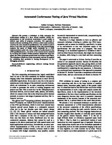
[18], and only a limited number of programmable logic devices are supported. Finally, several experimental implementations (such as that reported by [19]) to measure single parameters - such as CAN bit errors - rather than perform complete conformance testing have been described in the literature. Such implementations have typically used complex and non-trivial means, requiring customized hardware and software. In summary then, it can be observed that - to date – specialized hardware and / or software has been required to assist with CAN testing plans. In the following Section, a novel testing approach that relies only upon the use of low-cost, standard off-the-shelf hardware and software is described. III. TEST BED A. Architecture Real-time testing of a soft core CAN implementation is an extremely complicated procedure; the hardware that was employed for this purpose (as described in [5][33][20]) is shown in Fig 1. The hardware and software components are briefly described below, along with the use of VIO to generate the required test patterns.
II. PREVIOUS WORK IN THIS AREA One of the earliest CAN prototype controllers was named DBCAN [14]. This implementation was tested using a logic analyzer and a pattern generator circuit. As there was no standard for conformance testing at the time the prototype was developed, a commercial basic (as opposed to full) CAN controller was used as benchmark for verification. A major disadvantage of this scheme was the use of external interface modules to visualize the state of different DBCAN registers, and the testing procedure was somewhat limited in the number of signal channels that could be simultaneously analyzed. Since this is a needed requirement in the case of ISO standard conformance testing – the ability to visualize the state of large numbers of CAN registers simultaneously is a prerequisite – such a setup is limited in this respect. A slightly different verification technique was reported by [15]. Their technique employed custom design boards with 8051 microcontrollers and SJA1000 CAN controllers, but this method involved the design of specialized interface hardware and boards to assist with the testing plan. Specialized verification architecture for testing automotive protocols (including CAN) at both the module and chip level was proposed by [16]. Again, this work requires a specially designed CAN verification component as part of the silicon, while the selection and implementation of actual test sequences, along with the selection of a suitable means to monitoring bus signals, is left open for the tester. With respect to soft core CAN implementations, the CAN e-Verification (CANeVC) test bench has previously been described [17]. This commercial test facility requires a CAN specification core to be embedded in the netlist; this core then runs specific tests to verify the behavior of the CAN soft core. Again, this technique involves a time consuming development of a test bench using an expensive commercially available verification IP ; additionally, compatibility issues often arise when using CAN implementations other than the proprietary implementation
ISBN: 978-988-17012-5-1
Fig 1: Test Bench 1) Hardware • Two FPGA (XC3S500E programmed with CAN soft core) + ARM7 (LPC2138 as host controller) boards these boards are named as SC1 and SC2. The purpose of using two soft
WCE 2009
Proceedings of the World Congress on Engineering 2009 Vol I WCE 2009, July 1 - 3, 2009, London, U.K.
cores is to simultaneous verify their behavior as both CAN Transmitters/Receivers, additionally to generate special patterns on the CAN bus using VIO plus additional modules embedded within the soft core. • Two ARM7 microcontroller boards with integrated CAN controller and transceivers. These boards are used as receivers of CAN messages, for further verification of the messages sent by the CAN soft cores. These boards are also used to induce error’s on the CAN bus [13]. 2)
Software
• Xilinx ISE [21] for soft core programming, synthesis and routing / programming the FPGA. • Chipscope Pro is used as the primary analysis tool. The VIO core is used to generate and control different bit patterns. • The Keil uVision 3 IDE [22] with GNUARM tools. This free C compiler and toolchain was chosen for programming and debugging the Microcontroller boards. B. Use of Virtual I/O for Test pattern generation The Virtual Input/output (VIO) core can be used to analyze and drive internal FPGA signals in real-time [9]. The VIO cores can generate both asynchronous and synchronous signals, to be used as both input and output to / from the system. In the testing method proposed in this paper, synchronous outputs have been used as either a sole source of test pattern generator, or used in conjunction with soft modules added with the CAN functionality in the soft core, as described in [13]. VIO synchronous output has the ability to output a static 1, a static 0, or a pulse train of successive
values [13]. A pulse train is a 16-clock cycle sequence of 1's and 0's that is driven out of the core on successive clock cycles. The outputs can either be seen directly as the synchronous inputs, or a more comprehensive method is to use Chipscope ILA. Chipscope can analyze up to 16 internal signal ports in a single core, with each port having up to 256 signals with a capture depth of 16K samples. Different logical trigger conditions may also be setup to analyze signals for a certain value - as for example setting up a trigger to analyze when a CAN error frame is generated, or using ILA to capture multiple instances of stuff bits inside a capture window [9]. When using pattern generators, test vectors are first stored and are subsequently sent on the CAN bus when required; thus, the IUT can be put in different states as and when required, allowing its behavior and responses to be analyzed. In the proposed test bed, FPGA-based pattern generation has been employed, which is economical (as no extra costs are added to the test setup) but it is also flexible (it is added as a Verilog module to the main CAN core along with a VIO Core). This setup allows accurate production of the special conditions required to test conformance of CAN bit-timing; for example in test case 1 (to be reported in the next Section), it is required to delay a sample point by only two time quanta (on a recessive to dominant edge) on an IUT working as a transmitter [1]. Such precise control of test patterns could not be achieved with the previous setup. This test pattern was easily achieved by modifying the VIO Verilog module, without the need to modify the actual functionality of the CAN soft core (non-invasive testing). The Chipscope VIO was used as an (external synchronous) 5 bit pulse input “delay_add”, to generate an ‘n’ time quanta delay to the sample point. An example Verilog code is given below to help illustrate this:
always @ (posedge Clock or posedge Reset) begin if (Reset) Delay