Utilising Computational Fluid Dynamics (CFD) for the Modelling of Granular Material in Large-Scale Engineering Processes 1
1
Nicholas Christakis1, Pierre Chapelle1, Mayur K.Patel , Mark Cross , Ian Bridle2, Hadi Abou-Chakra3 and John Baxter3 1
Centre for Numerical Modelling and Process Analysis, University of Greenwich, Old Royal Naval College, Park Row, Greenwich, SE10 9LS London, UK {N.Christakis, P.Chapelle, M.K.Patel, M.Cross}@gre.ac.uk 2 The Wolfson Centre, University of Greenwich, Wellington Street, Woolwich, SE18 5PF London, UK
[email protected] 3 Department of Chemical and Process Engineering, University of Surrey, 6GU2 5XH 9042 Guildford, Surrey, UK {H.Abou-Chakra, J.Baxter}@surrey.ac.uk
Abstract. In this paper, the framework is described for the modelling of granular material by employing Computational Fluid Dynamics (CFD). This is achieved through the use and implementation in the continuum theory of constitutive relations, which are derived in a granular dynamics framework and parametrise particle interactions that occur at the micro-scale level. The simulation of a process often met in bulk solids handling industrial plants involving granular matter, (i.e. filling of a flat-bottomed bin with a binary material mixture through pneumatic conveying-emptying of the bin in core flow modepneumatic conveying of the material coming out of a the bin) is presented. The results of the presented simulation demonstrate the capability of the numerical model to represent successfully key granular processes (i.e. segregation/degradation), the prediction of which is of great importance in the process engineering industry.
1 Introduction In recent years significant effort has been put into the modelling of granular flows using a continuum mechanics approach ([1-2]). Although these models may be partially successful in capturing some characteristics of the flow, they do not incorporate essential information on material parameters, which are needed to model the various interactions between different particles or particles with their surrounding solid boundaries. Thus, they can not be used to simulate processes, which are of great imP.M.A. Sloot et al. (Eds.): ICCS 2002, LNCS 2329, pp. 743−752, 2002. Springer-Verlag Berlin Heidelberg 2002
744
N. Christakis et al.
portance in the process engineering industry (i.e. hopper filling/emptying, pneumatic conveying etc.), where these interactions lead to phenomena such as particle size segregation or particle degradation/breakage. On the other hand, micro-mechanical models are able to describe successfully the flow of granular material by accounting for all various types of interactions at the microscopic level ([3-4]). However, these models can only be applied to a small number of discrete particles, because of the complexity of the simulated processes. Therefore, such models are not suitable for large-scale process modelling, as considerable amounts of computing time are required for the simulation of processes that involve large numbers of particles. In the present paper it is argued that the micro-mechanical behaviour of different particle species in a multi-component granular mixture, can be parametrised and employed into a continuum framework in the form of constitutive models. In this way, by embedding the necessary micro-mechanical information for the individual particle species within the continuum theory, the modelling of multi-component granular mixtures is enabled. In this work, the continuum framework and the micro-mechanical parametrisations, employed to account for particle size segregation and breakage/degradation, are discussed. As an example, the simulation of a filling (through dilute phase pneumatic conveying) – emptying (in core flow mode) of a flat bottomed bin and further pneumatic conveying of the material coming out of the bin is presented. Conclusions are then drawn on the capability of the numerical model to realistically capture key granular processes (i.e. segregation /degradation) and its utilisation as a powerful computational tool by the process engineering community.
2 The Computational Framework The full set of flow equations was solved using PHYSICA, a Computational Fluid Dynamics (CFD) finite-volume code developed at the University of Greenwich. The PHYSICA toolkit is a three-dimensional, fully unstructured-mesh modular suite of software for the simulation of coupled physical phenomena (see e.g. [5-7]). The CFD code is utilised for the solution of conservation equations for mass and bulk momentum in the computational domain. Equations for energy were not solved because energy-linked flow parameters were accounted for in the micro-mechanical constitutive models, which link the granular temperature of the flow directly to the bulk velocity gradients via kinetic/theoretical considerations [8]. The effectiveness of this assumption will be demonstrated during the presentation of the numerical simulations. It should also be noted that the computational framework made use of micromechanical criteria in order to predict the flow boundary and the existence of stagnant zones (core flow mode) during the flow of granular materials [9]. A scalar equation was solved for each of the individual fractions fi of the mixture, representing the fractional volume of each of the material components in every computational cell. The summation of all individual fractions in a cell gave the total
Utilising Computational Fluid Dynamics (CFD)
745
amount of material present in that cell at a certain time. This sum is only allowed to take values between 0 (cell empty of material) and the maximum allowed packing fraction (always less than unity). The maximum allowed packing fraction is a function of the individual components’ shapes, sizes etc. and should be a model-input value, determined through experimental data. The scalar equation for each individual fi may be written as
∂fi / ∂t +
!$"#i (ub + useg)} = Si .
(1)
where ub is the bulk velocity (as results from the solution of the momentum equation), useg is a segregation “drift” velocity and Si is a source/sink term representing degradation in the i-th particle size class. Some details about the parametrisation of the segregation/degradation processes in the micro-mechanical framework are given in the following sections. 2.1 Parametrisation of Segregation The segregation “drift” velocities were analysed in the micro-mechanical framework, by using principles of kinetic theory [10]. In this way, for each material component three transport processes, that effectively lead to segregation, were identified: (a) Shear-induced segregation (representing the flow of coarser particles in the mixture across gradients of bulk velocity), (b) Diffusion, (representing the flow of finer particles down a concentration gradient) and (c) Percolation (representing the gravitydriven motion of the finer particles through the coarse phase in a mixture). Functional forms of all three “drift” components were derived and transport coefficients were calculated for each mixture phase by using linear response theory and integrating the relevant time correlation functions in a Discrete Element Method (DEM) framework [3]. A full description and analysis of the functional forms of the derived constitutive equations for all three mechanisms, as well as validation results are given in [11]. 2.2 Parametrisation of Degradation Two distinct approaches have been incorporated in the numerical model for the modelling of degradation, according to whether the granular mixture was quite dense or quite dilute. The former case (dense-phase mixture) can be modelled in an Eulerian framework by employing population balance models to construct source terms for Equation (1), which depend on material properties and local boundary conditions (e.g. [12]). Of more engineering importance however, is the case of dilute-phase mixtures (dilute-phase pneumatic conveying systems can be found in most bulk solids handling plants), where the particles are fully dispersed in the fluid flow. The present paper concentrates on dilute-phase mixtures and their degradation modelling. An Eulerian/Lagrangian approach for the fluid and the particle phases, respectively, was adopted in this case, where a stochastic simulation procedure was included to represent particle degradation caused by particle-wall collisions.
746
N. Christakis et al.
A particle on its way through a pneumatic conveying line frequently collides with the pipe and bend walls. The force produced on the particle at the time of impact may lead to its degradation. Particle damage can occur in two principal modes according to the level of applied stresses and the material properties, namely breakage and abrasion (particle surface damage). Some of the most important parameters affecting particle impact degradation are the particle velocity, the collision angle, the properties of the particle and wall materials and the particle size and shape. Since the main degradation usually occurs at bends [13], only collisions of particles with bend walls were assumed to give rise to particle damage and were considered in the present work. Particle degradation was simulated using a stochastic calculation procedure, based on the definition of “degradation rules”, formulated from two characteristic functions, namely the probability for a particle to degrade and the size distribution of the degradation products. In the model, the probability of degradation and the size distribution of the degradation products were calibrated from experimental impact degradation studies. A statistical factor for the degradation process was introduced, since the effects of parameters such as particle shapes, particle orientation at the impact point, wall roughness etc., were not explicitly considered during the solution procedure.
3 Numerical Simulations To demonstrate the capabilities of the presented model, a test case was chosen, which represents a full process of handling of granular material and is an example of a process commonly met in bulk solids handling operations. (a) inlet bend (b) cylindrical flat-bottomed bin (c) second bend Arrows represent the direction of material flow. Fig. 1. Schematic representation of the simulated system.
The process involves the modelling of the pneumatic conveying of an initially mono-sized material in dilute-phase. The material, after travelling in a pipe with a bend, degrades into various size classes. The output of the pneumatic conveyor is treated as a binary 50-50 mixture (50%/50% coarse/fine particles) of 4.6:1 particle size ratio and fills a cylindrical flat-bottomed bin. Once the bin is filled, the material is assumed to have reached its maximum packing fraction and its initial segregated distribution is set according to theoretical predictions and experimental data [14]. The modelling of the discharge of the material from the bin follows and the effects of segregation in the mixture during core flow discharge are presented. The output of the
Utilising Computational Fluid Dynamics (CFD)
747
material discharge is then taken through pneumatic conveying system with a bend, and the final distribution of the mixture is recorded after its final exit, see Figure 1. 3.1 Dilute-Phase Pneumatic Conveying of Mono-sized Material The calculation domain consists of a 90° pipe-bend with an internal diameter of 0.05 m and a ratio of the bend radius to the pipe diameter equal to 3.6, see Figure 2a. The conveyed material was mono-sized spherical particles of 931 µm diameter and 3 solids density of 2000 kg/m . This component simulation was performed for a con3 veying air velocity of 14 m/s and particle concentration of 10 kg/m , a typical value for industrial operating conditions under which particle degradation constitutes a problem. The particle velocity at the inlet of the bend was assumed to be equal to the air velocity and homogeneously dispersed.
a
b
Fig. 2. Numerical grid of (a) the pipe bend and (b) cylindrical flat-bottomed bin
For these impact degradation calculations, the size range between 0 and 1000 µm was divided into evenly-spaced size intervals. The dependence of the particle degradation probability and the fragment size distribution on the particle velocity and the particle size were determined from experimental data, obtained from 90° impact degradation experiments on single particles, using a rotating disc accelerator type degradation tester [15]. This test facility is a bench-scale unit for assessing degradation by impact. It can control both the speed of the particles and the angle of impact. It is well known that degradation caused by solid particle impact varies with particle velocity. In the current degradation tester, the effect of particle size and/or shape is minimal on the particle travelling velocity. This is important because when testing bulk solids of various size or shape distributions, homogeneous particle velocity is essential. A restitution coefficient of 0.8 was employed for the calculations during the rebound process. In this way, particles impacting on the walls of a bend were let to degrade according to their degradation probability. In the instance of a degradation event, the original particles were split into a number of daughter particles, whose sizes were distributed according to the degradation product size distribution. Each daughter particle was given a fraction of the momentum of the original particle equal to the ratio of the daughter and original particle volumes and the new particle velocities resulting from the rebound process were calculated.
748
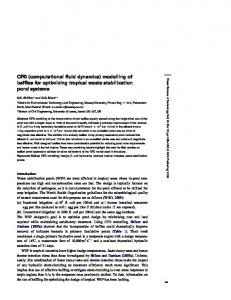
N. Christakis et al. 100 bend inlet bend outlet
80
60 50.1
40
20 6.0
7.3
9.4
9.3
8.2
9.3 0.2
0 0-150
150-300 300-425 425-500 500-600 600-710 710-850 850-1000 Size range (microns)
Fig. 3. Particle size distribution at the bend inlet and outlet of the filling conveying system.
The calculated particle size distribution in the bend outlet cross-section is presented in Figure 3. Almost all the original particle sample fed into the inlet was seen to have degraded (mass fraction of original 931 µm diameter particles at the outlet was 0.2 %) and a broad size distribution of the particles was predicted at the bend outlet. The proportion of debris of size below 150 µm was very high, whereas the size intervals ranging from 150 µm to 850 µm were approximately evenly populated, with a mass fraction value less than 10 % in each interval. It should be noted that the use of “degradation rules” based on 90° impact degradation tests leads most likely to overpredicting the degradation amount occurring in the bend. In reality, the smaller the impact angle, the smaller the force produced on the particle and hence, less amount of degradation should result. Refinement of the present model, by incorporating the effect of the impact angle on the degradation processes, is currently underway.
3.2 Discharge of a Flat-Bottomed Bin in Core Flow Mode The output of the pneumatic conveyor was used to fill a cylindrical flat-bottomed bin of 65 cm diameter, 94 cm height and 6.5 cm orifice at the bottom, around its central axis. For reasons of simplification, the pneumatic conveyor output size distribution was represented as a 50-50 binary mixture of 4.6:1 particle size ratio. It consisted of fines of size below 150 µm (volume averaged diameter of 120 µm) and coarse particles of size between 150 µm and 850 µm (volume averaged diameter of 555 µm). The material was assumed to be at its maximum packing fraction (total solids fraction of 0.5) and resting in the bin at its angle of repose (34º). The initial segregated profile was fitted according to theoretical predictions and experimental data [14], so that only coarse particles could be found around the central axis of the bin, then there existed a region where the mixture composition was 50-50 and only fine particles were concentrating close to the walls of the bin. Because of the material properties and the vessel geometry, it was predicted through the micro-mechanical flow criteria [9] that the discharge of the mixture was going to occur in core flow mode (where stagnant material regions exist). Due to the axisymmetric nature of this case, a semi-3D geometry
Utilising Computational Fluid Dynamics (CFD)
749
o
was chosen, with a slice of 5 angle being simulated. The simulated bin geometry and applied mesh are shown in Figure 2b. During the initial stages of discharge (less than 3% of the total emptying time), the central part was observed to collapse, thus creating a channel. Once the channel reached the top surface, this began to descend and steepen until it reached the material angle of repose. Thereafter, the material emptied from the bin very slowly through avalanching from the surface region of the bulk, with the angle of repose and the central channel always being maintained (this mode of emptying is also known as “ratholing”). Eventually, a stagnant region was left in the domain, with no more material exiting the bin. The final stagnant material was also maintained at the angle of repose. The total bin emptying time until the creation of the final stagnant region was predicted by the model to be approximately 200 s, a result which is in good agreement with experimental observations of core flow bin discharges of similar dimensions (e.g. [9]). The evolution of the interface of the total material fraction and the individual components (fines and coarse) at various points in time is depicted in Figure 4. Segregation was obvious during the intermediate stage of the discharge, when the 50-50 mixture region was discharging. As can be observed in the fourth temporal snapshot of Figure 4, the moving coarse particles were making their way towards the interface, while the finer particles of the flowing zone were moving away from the interface (this phenomenon is known as “rolling segregation”). Once the 50-50 region disappeared, then only fine particles were seen to exit the bin. This is demonstrated in Figure 5, where the mass percentage in the mixture (averaged over the outlet region) of each of the individual fractions are plotted against normalised emptying time. Total
Fines
Coarse
t/Tmax
0.004
0.007
0.012
0.02
0.05
0.1
0.3
0.6
0.8
1.0
Fig. 4. Interface profiles for the individual/total solids fractions. Intensity of gray shade indicates increase in material.
The graph is split in three regions corresponding to the three regions of the initial vessel filling state. Region 1, initially containing coarse particles only, emptied very
750
N. Christakis et al.
quickly, hence the sharp decrease (increase) in the coarse (fine) particle curve. Region 2, initially containing the 50-50 mixture, exhibited very sharp peaks, thus indicating the effects of rolling segregation with the mixture composition at the outlet alternating between mostly coarse and mostly fines. Region 3, initially containing mostly fine particles, appeared much later into the discharge, with the mixture at the outlet containing almost exclusively fines and the occasional spike appearing, indicating that some coarse (remnants of the 50-50 mixture initial distribution) exited the domain. This result was anticipated and is in agreement with theoretical predictions and experimental observations.
Fig. 5. Mass percentage in the mixture of the individual fractions (averaged at the outlet) plotted against normalised emptying time during core flow discharge.
3.3 Pneumatic Conveying System Located Downstream of the Storage Vessel The final simulation was performed using the same flow conditions (pipe bend geometry, conveying air velocity and particle concentration) as for the upstream conveying system, except the orientation of the bend (see Figure 1). As it has been shown, the composition of the outgoing particles at the outlet of the bin varied during the vessel discharging due to segregation phenomena. The calculations of the particle degradation in the downstream pipe bend were performed for four different averaged compositions of coarse particles (d = 555 µm) and fines (d = 120 µm) at the bin outlet, representative of the various regimes identified on the segregation curve. The simulated input compositions are given in the table in Figure 6. Similarly to the filling conveying system, significant degradation of the particles occurred in the bend and the particle size distributions were considerably different in the bend inlet and outlet cross-sections. Figure 6 presents for times 1 to 4 the total mass percentage of coarse particles (now defined as particles with diameter between 150 µm and 555 µm) and fines (diameter below 150 µm) in the bend outlet. For time 1 about 40 % of the particles fed into the bend were converted into fines of size below 150 µm. The same was true for about 30% of the coarse particles at time 2 and approximately 10% of the coarse particles at time 3. This result indicated that with de-
Utilising Computational Fluid Dynamics (CFD)
751
creasing percentage of incoming coarse particles in the bend, the percentage of them that were converted into fines also decreased. This effect could be attributed to the fact that with increasing numbers of fines coming into the pneumatic conveyor at the latter stages of the core flow bin discharge, the probability of impact between a coarse particle and the bend wall also reduced, hence leading to reduced numbers of coarse particles being allowed to collide with the wall and degrade. c o a rse
fin es
Coarse
1 00 %
Fines
80 %
Time1
100%
0%
60 %
Time2
70%
30%
40 %
Time3
30%
70%
20 %
Time4
0%
100%
0% tim e 1
tim e 2
tim e 3
tim e 4
% bin outlet composition
Fig. 6. Proportion of coarse particles (150 µm < d < 555 µm) and fines (d < 150 µm) at the bend outlet of the conveying system downstream the storage vessel.
4 Conclusions In this paper, a computational framework was presented for the modelling of granular material flows, based on Computational Fluid Dynamics and implemented with micromechanical constitutive models for the effective representation of the interactions between particles at the microscopic level. The presented simulations demonstrated the potential capability of the model to realistically represent key granular processes (segregation/degradation), which are of great importance in the process engineering industry. The developed model represented realistically the dilute-phase pneumatic conveying, both upstream and downstream of a core flow bin, by employing “degradation rules” based on experimental studies of single-particle-impact degradation. The process of core flow bin discharge showed the correct trend for segregation, in agreement with theoretical and experimental results. It should also be noted that the presented modelling of core flow in a continuum mechanics framework is believed to be unique. Further development of the model and inclusion of parametrisations for the modelling of aggregation will make it a powerful computational tool for engineers, which will aid them in the characterisation of granular material flows and the processes involved.
References 1.
Tardos, G.I.: A fluid mechanistic approach to slow, frictional flow of powders, Powder Tech. 92 (1997) 61-74
752 2. 3. 4. 5. 6.
7.
8.
9.
10. 11.
12. 13. 14.
15.
N. Christakis et al. Karlsson, T., Klisinski M., Runesson, K.: Finite element simulation of granular material flow in plane silos with complicated geometry, Powder Tech. 99 (1999), 29-39 Baxter, J., Tüzün, U., Burnell, J., Heyes, D.M.: Granular Dynamics Simulations of Twodimensional Heap Formation, Phys. Rev. E 55 (1997), 3546-3554 Yang, S., Hsiau, S.: The Simulation and Experimental Study of Granular Materials Discharged from a Silo with the Placement of Inserts, Powder Tech. 120 (2001), 244-255 Cross, M.: Computational Issues in the Modelling of Materials Based Manufacturing Processes, J. Comp Aided Mats Design 3 (1996), 100-116 Bailey, C., Taylor, G.A., Bounds, S.M., Moran, G.J., Cross, M.: PHYSICA: A Multiphysics Framework and its Application to Casting Simulation. In: Schwarz, M.P. et al.(eds): Computational Fluid Dynamics in Mineral & Metal Processing and Power Generation, (1997) 419-425 Pericleous, K.A., Moran, G.J., Bounds, S., Chow, P., Cross, M.: Three Dimensional Free Surface Flows Modelling in an Unstructured Environment for Metals Processing Applications, Appl. Math. Modelling 22 (1998), 895-906 Nikitidis, M.S., Tüzün, U., Spyrou, N.M.: Measurements of Size Segregation by Selfdiffusion in Slow-Shearing Binary Mixture Flows Using Dual Photon Gamma-ray Tomography, Chem. Eng. Sci. 53 (1998), 2335-2351 Nedderman, R.M.: The Use of the Kinematic Model to Predict the Development of the Stagnant Zone Boundary in the Batch Discharge of a Bunker, Chem. Eng. Sci. 50 (1995), 959-965 Zamankhan, P.: Kinetic theory of multicomponent dense mixtures of slightly inelastic spherical particles, Phys. Rev. E 52 (1995), 4877-4891 Christakis, N., Patel, M.K., Cross, M., Baxter, J., Abou-Chakra, H., Tüzün, U.: Continuum Modelling of Granular Flows using PHYSICA, a 3-D Unstructured, Finite-Volume Code. In: Cross, M., Evans, J.W., Bailey, C. (eds): Computatinal Modeling of Materials, Minerals and Metals Processing, San Diego, CA, TMS (2001) 129-138 Hogg, R.: Breakage Mechanisms and Mill Performance in Ultrafine Grinding, Powder Tech. 105 (1999) 135-140 Bemrose, C.R., Bridgwater, J.: A Review of Attrition and Attrition Test Methods, Powder Tech., 49 (1987) 97-126 Salter, G.F.: Investigations into the Segregation of Heaps of Particulate Materials with Particular reference to the Effects of Particle Size. Ph.D. Thesis, University of Greenwich, London (1999) Kleis, I.R., Uuemois, H.H., Uksti, L.A., Papple, T.A.: Centrifugal Accelerators for Erosion Research and Standard Wear Testing. In: Proceedings of the International Conference on the Wear of Materials, Dearborn, MI, ASTM (1979) 212-218