Home
Search
Collections
Journals
About
Contact us
My IOPscience
Variable stiffness property study on shape memory polymer composite tube
This article has been downloaded from IOPscience. Please scroll down to see the full text article. 2012 Smart Mater. Struct. 21 094021 (http://iopscience.iop.org/0964-1726/21/9/094021) View the table of contents for this issue, or go to the journal homepage for more
Download details: IP Address: 219.217.246.36 The article was downloaded on 01/09/2012 at 03:41
Please note that terms and conditions apply.
IOP PUBLISHING
SMART MATERIALS AND STRUCTURES
Smart Mater. Struct. 21 (2012) 094021 (9pp)
doi:10.1088/0964-1726/21/9/094021
Variable stiffness property study on shape memory polymer composite tube Yijin Chen1 , Jian Sun1 , Yanju Liu2 and Jinsong Leng1,3 1
Centre for Composite Materials and Structures, Science Park of Harbin Institute of Technology (HIT), PO Box 3011, No. 2 YiKuang Street, Harbin, People’s Republic of China 2 Department of Aerospace Science and Mechanics, Harbin Institute of Technology (HIT), PO Box 301, No. 92 West dazhi Street, Harbin, People’s Republic of China E-mail:
[email protected]
Received 6 February 2012, in final form 29 May 2012 Published 31 August 2012 Online at stacks.iop.org/SMS/21/094021 Abstract As a typical smart material, shape memory polymers (SMPs) have the capability of variable stiffness in response to external stimuli, such as heat, electricity, magnetism and solvents. In this research, a shape memory polymer composite (SMPC) tube composed of multi-layered filament wound structures is investigated. The SMPC tube possesses considerable flexibility under high temperature and rigidity under low temperature. Significant changes in effective engineering modulus can be achieved through regulating the environment temperature. Based on the classical laminated-plate theory and Sun’s thick laminate analysis, a 3D theory method is used to study the effective engineering modulus and modulus ratio of the SMPC tube. The tensile test is conducted on the SMPC tube to verify the accuracy of the theoretical method. In addition, the effective engineering modulus and modulus ratio are discussed under different fiber-winding angles and fiber volume fractions of the SMPC tube. The presented analysis provides meaningful guidance to assist the design and manufacture of SMPC tubes in morphing skin applications. (Some figures may appear in colour only in the online journal)
1. Introduction
order to reduce the energy consumption of actuators, low in-plane stiffness of the morphing skin is desired during the deformation process [4–6]. Traditional stiff skin like fish scales is one kind of morphing skin, which was first proposed by Long et al [7]. Although this kind of skin can meet the demands of an aircraft wing in load-bearing capability and shape change, it cannot meet the demands of smooth surface and continuous and aerodynamic performance. Another possibility involves rubbery material, which possesses higher flexibility and elasticity [8]. While this kind of morphing skin can satisfy the requirements of deformation and continuity, the entire load-bearing capacity is decreased due to the material’s low stiffness. The third kind used to realize the deformation function is a corrugated structure [9, 10], which can exhibit a corrugated shape in one direction and shows extreme anisotropic behavior. In addition, the material has a larger deformation in the corrugated direction and a high bending stiffness in the direction perpendicular to the corrugation. However, the deformability is usually limited in one direction.
Historically, aircraft have been designed according to their particular missions, and usually optimized in the most relevant flight performance. However, the geometry of a wing is not always optimal through continuously varying flight parameters, such as altitude, weight and Mach number. Morphing aircraft can address this problem through changing their wing shapes to adapt to the outside flight environment [1, 2]. They offer great potential for performance improvements over traditional aircraft. Morphing skin is one of the key techniques to realize morphing aircraft [3]. The morphing skin should undergo enough deformation to appropriately respond to significant changes of chord length, span length, sweepback angle and wing area that may be accomplished by the aircraft wing. Meanwhile, the morphing skin should also possess enough out-of-plane stiffness to maintain the aerodynamics configuration during the deformation process. However, in 3 Author to whom any correspondence should be addressed.
0964-1726/12/094021+09$33.00
1
c 2012 IOP Publishing Ltd Printed in the UK & the USA
Smart Mater. Struct. 21 (2012) 094021
Y Chen et al
Although these skins mentioned above can realize the function of deformation more or less, a critical shortcoming still exists, namely the skin stiffness is always kept as a constant. In order to keep the constant skin stiffness that was designed according to the critical flight speed, constant energy consumption should be provided during the flight. However, the actual flight speed is always lower than the critical speed, which would result in a waste of energy if a constant skin stiffness were being used. In recent years, a new kind of variable stiffness skin composed of fluidic flexible matrix composite tube and flexible matrix was proposed and studied [11–13]. One of the key components is the fluidic flexible matrix composite (F2 MC) tube, namely a variable stiffness tube. Through controlling the inner fluid, significant change in the axial elastic modulus of the variable stiffness tube can be achieved. Recently emerged smart materials and their composites open an avenue to the development of morphing aircraft. As a typical smart material, shape memory polymers (SMPs) are a class of stimulus-responsive materials with the ability to undergo a large recoverable deformation upon external stimulus, such as heat, electricity, magnetism and solvents [14–16]. Below their glass transition temperatures Tg , SMPs are stiff. Once heated above Tg , they will be relatively soft and consequently they can be deformed into a desired temporary shape through applying an external force. Their temporary shape can be maintained for long time if this external force is removed after cooling. Finally, upon re-heating, their temporary deformed shape will be automatically recovered into the original permanent shape [17]. Although significant modulus change of pure SMP material can be achieved, the limited load-bearing capability in the heated state hinders their further applications. In view of this, shape memory polymer composite has attracted the attention of many researchers. Leng et al [18] studied the shape memory properties of pure styrene-based SMPs and its nanocomposite filled with nanocarbon particles, which demonstrated the feasibility of infrared light actuation (in vacuum). The shape memory properties of styrene-based shape memory polymer composite (SMPC) reinforced by carbon fiber fabrics were further investigated by Lan et al [19], who successfully completed the SMPC hinge actuation with a resistor heater and showed that the glass transition of SMPC is higher than pure SMP by 10 ◦ C. Yin et al [20] also completed the actuation of SMP skin embedded with heating wire springs by a DC motor. In addition, SMPCs filled with carbon nanotubes [21], Ni powder [22] and carbon nanofibers [23] have been studied, which could be used to address the heated issue. In order to decrease the weight and volume, and improve the variable stiffness performance of the morphing skin, a new SMPC tube composed of multi-layered filament wound structures has been fabricated and researched in this paper. Compared with an F2 MC tube [24], an SMPC tube possesses better variable stiffness capability and lower weight with the same small size. Then, based on classical laminated-plate theory and the thick laminate analysis of Sun [25], the theoretical values of the engineering moduli are determined.
Figure 1. SMPC tube in cylindrical coordinate system.
In comparison with the tensile test result, the analysis method is deemed to possess satisfactory accuracy in predicting the axial elastic modulus and modulus ratio of the SMPC tube. In addition, the elastic modulus and shear modulus are discussed under different fiber-winding angles and fiber volume fractions. The prediction results could serve as a reference in SMPC tube design and application.
2. Analysis procedure of SMPC tube 2.1. Stress and strain relation The SMPC tube is considered to be homogeneous orthotropic, and has an opposite fiber orientation (±φ) with respect to the axial direction of the tube. For convenience, the cylindrical coordinate system is adopted to analyze the SMPC tube, as shown in figure 1. The coordinates are denoted by r as the radial, θ as the hoop, and z as the axial coordinates of the cylinder. For the anisotropic SMPC tube, the stress and strain transformation of the kth layer from material coordinate to cylindrical coordinate is given by [26] (k) C¯ 11 C¯ 12 σz C¯ 12 C¯ 22 σθ ¯ σ C13 C¯ 23 r = 0 0 τθ r τ 0 0 zr τzθ C¯ 16 C¯ 26
C¯ 13 0 C¯ 23 0 C¯ 33 0 0 C¯ 44 0 C¯ 45 ¯ C36 0
(k) (k) εz C¯ 16 ε C¯ 26 θ ε C¯ 36 r . (1) γθr 0 γzr 0 γzθ 0 C¯ 66
0 0 0 ¯ C45 C¯ 55
2.2. Laminated-plate theory (k) The off-axis stiffness constants in matrix [C¯ ij ] can be obtained from the on-axis coordinate constants in matrix (k) [Cij ], using a stiffness transformation matrix written as [27] (k)
(k)
ε ] [C¯ ij ] = [Tilσ ]−1 [Clm ][Tmj
(2)
ε ] are the base changes of stress where matrices [Tilσ ] and [Tmj and strain, respectively. The stiffness constants of matrix
2
Smart Mater. Struct. 21 (2012) 094021
Y Chen et al
(k)
[Cij ] are given as follows [28]: 1 − v12 v21 − v13 v31 − v23 v32 − 2v21 v13 v32 E11 E22 E33 v12 + v13 v32 1 − v23 v32 , C12 = , C11 = E22 E33 1 E11 E33 1 v13 +v12 v23 C13 = E11 E22 1 1 − v13 v31 v23 + v21 v13 C22 = , C23 = , E11 E33 1 E11 E22 1 1 − v12 v21 C33 = E11 E22 1 G44 = G23 , G55 = G31 , G66 = G12 1=
(3)
When each layer of the laminated plate exhibits the properties of fiber reinforced composite materials, the matrix material is isotropic and the fiber is transversely isotropic; according to the ratio of the mixture, its elastic constants can be expressed as E11 = Vf Ef 11 + Vm Em , Ef 22 Em E22 = E33 = , Ef 22 Vm + Em Vf Gf 12 Gm G12 = G13 = Gf 12 Vm + Gm Vf Gf 23 Gm G23 = , Gf 23 Vm + Gm Vf v12 = v13 = Vf vf 12 + Vm vm , v23 = Vf vf 23 + Vm vm
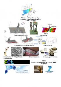
Figure 2. Filament wound of SMPC tube.
(4)
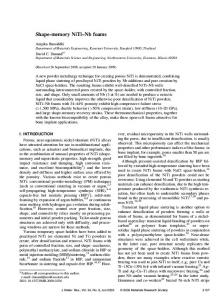
Figure 3. SMPC tube specimens.
where Ef 11 , Ef 22 , Gf 12 , Gf 23 , vf 12 and vf 23 are the material constants of the fiber, Em , vm and Gm are the material constants of the matrix, and Vf and Vm are the volume fractions of fiber and matrix materials, respectively.
3. SMPC tube fabrication and experiment test 3.1. SMPC tube fabrication
2.3. Effective engineering modulus and modulus ratio R S, VF 62 SMP material (purchased from CRG) The Veriflex used in this study was styrene-based shape memory resin with a glass transition of 62 ◦ C, which is a typical thermosetting resin. The uncured SMP resin was prepared by mixing the styrene-based shape memory resin with crosslink agent in the fixed proportion, and then stirring uniformly at room temperature. As shown in figure 2, the SMPC tube was wet filament wound using a computer-controlled filament-winding machine (SKLCR 120/500, Qier Machine Tool Group). Before filament winding, a stainless steel mandrel (diameter: 4 mm) was prepared with release agent pre-coated on the surface. Then the ends of the mandrel were connected to the designed stainless steel connections, which were fixed by two three-jaw chucks. The uncured SMP resin was contained in the resin bath, and the carbon fiber could pass through the resin bath before winding. Through controlling the computer, the carbon fiber (T300, 3 K) was spiral wound on the mandrel at ±40◦ angle. After curing in a closed mold at 75 ◦ C for 24 h, the SMPC tube specimen was obtained with an inner diameter of 4 mm and an outer diameter of 5.8 mm, as shown in figure 3. Through measurement and calculation, the actual fiber-winding angle is ±39◦ , and the fiber volume fraction is 0.3.
After the stiffness constants of each layer have been obtained, the stiffness constants of the SMPC tube could be derived based on the thick laminate analysis [25]. According to the relation of the compliance matrix and stiffness matrix, the compliance matrix of the SMPC tube can be obtained, and then the effective engineering moduli for the SMPC tube can be written as 1 1 1 Eθ = Er = Ez = S11 S22 S33 1 1 1 Gθ r = Gzr = Gzθ = . (5) S44 S55 S66 Once the engineering moduli of the SMPC tube are determined, the effective cold state modulus (T = 23 ◦ C) Ec and heated state modulus (T = 90 ◦ C) Eh can be simultaneously obtained. Based on this fact, the modulus ratio of R is defined as Ec . (6) Eh When the expressions of the effective engineering modulus and modulus ratio are obtained, they can be used to calculate the effective engineering modulus and modulus ratio of the SMPC tube. R=
3
Smart Mater. Struct. 21 (2012) 094021
Y Chen et al
Figure 6. Experimental curves of engineering stress versus strain of SMPC tube.
Figure 4. Experimental setup of SMPC tube.
Table 1. Basic material parameters of the fiber and matrix. Material
Property
Value
Carbon fiber (T300)
E11 (GPa) E22 (GPa) G12 (GPa) v12 v23 Em (MPa) (clod state) Em (MPa) (heated state) v
221 13.8 9 0.2 0.25 By tensile test By tensile test 0.35
Matrix (SMP)
one that we chose is approximately equal to the average value of the experimental results. The experimental curve of engineering stress versus strain of pure SMP material is depicted in figure 5. The engineering stress in the figure is calculated as the tensile force divided by the cross sectional area of the SMP specimen. The strain is approximated as the displacement divided by the original length of the SMP specimen. The modulus is determined by calculating the slope of the linear portion of the stress–strain curve. It can be seen that the axial effective engineering elastic moduli are 928 MPa in the cold state and 9.9 MPa in the heated state, respectively. Thus, a modulus-changing ratio of about 93 is obtained. The experimental curve of engineering stress versus strain of the pure SMPC tube is depicted in figure 6. The only difference is that the engineering stress in this figure is calculated as the tensile force divided by the annular cross sectional area (the area between the inner radius and outer radius) of the SMPC tube specimen. As shown in this figure, the axial effective engineering elastic moduli are 2692.5 MPa in the cold state and 34.1 MPa in the heated state. The predicted results based on theory analysis of this current research are obtained and compared with the experimental results. The basic material parameters of the fiber and matrix in the theory analysis are listed in table 1. The comparison between predicted results and experimental results is demonstrated in table 2. Although the modulus and modulus ratio of experimental results are less than the theory predicted values, it still can be found that a modulus ratio
Figure 5. Experimental curves of engineering stress versus strain of SMP.
3.2. Experimental test In order to obtain the axial effective engineering elastic modulus, the pure SMP material and the SMPC tube with a length of 112 mm were tested in two states: cold state (T = 23 ◦ C) and heated state (T = 90 ◦ C). The tensile tests were performed on a Materials Testing Machine (INSTRON5569) with a constant loading rate of 1 mm min−1 , as shown in figure 4. The values of force and displacement were recorded by the computer during the tensile test progress.
4. Results and discussion 4.1. Experimental results and analysis In this section, a cold state of 23 ◦ C (Tg + 20) were chosen in the tensile test to study the mechanical properties of the SMPC tube. All experiments were conducted on four specimens, and the 4
Smart Mater. Struct. 21 (2012) 094021
Y Chen et al
Figure 7. Curves of elastic modulus Ez versus fiber-winding angle of SMPC tubes with different fiber volume fractions: (a) cold state and heated state moduli; (b) modulus ratio. Table 2. Comparison of experiment and predicted results.
Experimental results Predicted results
Axial elastic modulus (cold state) (MPa)
Axial elastic modulus (heated state) (MPa)
Modulus ratio
2692.5 3065.4
34.1 36.2
79.0 84.7
of 79 is measured, which agrees closely with the theoretical prediction of 84.7. This small error may be attributed to the fact that the fiber-winding angle and fiber volume fraction used in the theoretical predicted results are not exactly the same as the actual values for the fabricated specimen. The comparison shows that the theory analysis method used in the current research can describe the axial effective elastic modulus accurately. In addition, all the effective engineering moduli are not independent: they are obtained based on the same theory and derivation. The axial effective elastic modulus is the primary concern of the current study. As a tube structure, it is convenient and easy to obtain the axial elastic modulus, and the experimental result would be closer to the true value. Therefore, the experimental result of the axial elastic modulus could be one of the best choices to validate the accuracy of the theoretical method. Arguably, once the validity of the theoretical method has been proved by the axial tensile test result, the theory analysis method can be used to predict the other effective engineering elastic modulus and shear modulus in cold and heated states, as well as their modulus ratio. The results could serve as assistance to design and fabricate the SMPC tube.
to distinguish the curves clearly in the figure, five curves were chosen in the analysis of the modulus and nine curves were chosen in the analysis of the modulus ratio. 4.2.1. Effective engineering elastic modulus Ez . The relation between elastic modulus Ez (and modulus ratio) and fiber-winding angle of the SMPC tubes with different fiber volume fractions is depicted in figure 7. It is observed from figure 7(a) that when the fiber volume fraction is a constant, along with increasing fiber-winding angle, the elastic modulus in the cold state exhibits a trend of first decreasing rapidly then approaching a constant. It reaches its maximum value at 0◦ and decreases to its minimum value at 90◦ , which is mainly attributed to the material properties of the fiber. As a kind of transversely isotropic material, the elastic modulus of the carbon fiber in the axial direction is much larger than that in the radial direction. A similar phenomenon exists in the change of elastic modulus in the heated state. Besides, the elastic modulus in the cold state is larger than that in the heated state while the fiber-winding angle and fiber volume fraction remain constant. This can be explained by the much larger elastic modulus of the matrix (SMP) in the cold state. In order to show the reinforced effect of the fiber, the elastic modulus curves of pure SMP were added to figure 7(a). Figure 7(b) indicates that the modulus ratio increases along with increasing fiber-winding angle, when the fiber volume fraction is a constant. The maximum modulus ratio at 90◦ decreases from 93 to 58 when the fiber volume fraction changes from 0.1 to 0.9. This is because the fiber does not possess the function of variable modulus while the environment temperature is changing. Moreover, the relative volume increase of the fiber in the SMPC tube makes a positive contribution to the increase of the elastic modulus in
4.2. Analysis and discussion of SMPC tube For the essential component of carbon fiber, its material parameter plays an important role in the effective engineering modulus of the SMPC tube. To further study the effect of fiber-winding angle and fiber volume fraction on the effective engineering modulus and modulus ratio, a series of predicted curves was obtained based on the theory analysis method. The other parameters remain unchanged while the fiber-winding angle and fiber volume fraction are being discussed. In order 5
Smart Mater. Struct. 21 (2012) 094021
Y Chen et al
Figure 8. Curves of elastic modulus Eθ versus fiber-winding angle of SMPC tubes with different fiber volume fractions: (a) cold state and heated state moduli; (b) modulus ratio.
Figure 9. Curves of elastic modulus Er versus fiber-winding angle of SMPC tubes with different fiber volume fractions: (a) cold state and heated state moduli; (b) modulus ratio.
the two states, which results in a decrease of the maximum modulus ratio. In other words, a relative volume increase of the fiber always has a negative effect on the modulus ratio.
and fiber-winding angle of SMPC tubes with different fiber volume fractions is depicted in figure 9. As shown in figure 9(a), when the fiber volume fraction is a constant, the elastic moduli in both states vary insignificantly with changing fiber-winding angle. They reach their maximum value at 45◦ and decrease to their minimum value at 0◦ (or 90◦ ). When the fiber volume fraction changes from 0.1 to 0.9, the relative variations of the maximum value to minimum value of elastic modulus will change from 10.8% to 6.6% in the cold state, and 10.9% to 7.7% in the heated state. As shown in figure 9(b), the corresponding minimum modulus ratio occurs at 45◦ , and the maximum modulus ratio occurs at 0◦ (or 90◦ ). It should be noted that the maximum modulus ratio would change from 93 to 58 when the fiber volume fraction increases from 0.1 to 0.9.
4.2.2. Effective engineering elastic modulus Eθ . The relation between elastic modulus Eθ (and modulus ratio) and fiber-winding angle of SMPC tubes with different fiber volume fractions is shown in figure 8. It can be seen from figure 8(a) that when the fiber volume fraction is a constant the elastic moduli in both states remain almost unchanged for fiber-winding angle lower than 45◦ , and then increase rapidly with increasing fiber-winding angle. They reach their maximum value at 90◦ and decrease to their minimum value at 0◦ . As shown in figure 8(b), with increasing fiber-winding angle, the modulus ratio decreases when the fiber volume fraction is a constant. The maximum modulus ratio at 0◦ decreases from 93 to 58 when the fiber volume fraction changes from 0.1 to 0.9. This can be attributed to the fact that the decreasing relative volume in the fiber plays a negative role in the increase of the elastic modulus in the two states, which results in an increasing maximum modulus ratio.
4.2.4. Effective engineering shear modulus Gθ r . The relation between shear modulus Gθ r (and modulus ratio) and fiber-winding angle of SMPC tubes with different fiber volume fractions is depicted in figure 10. As seen from figure 10(a), when the fiber volume fraction is a constant, insignificant change will occur in the value of shear modulus with changing fiber-winding angle. As shown in figure 10(b), along with increasing fiber-winding angle, the modulus ratio
4.2.3. Effective engineering elastic modulus Er . The relation between elastic modulus Er (and modulus ratio) 6
Smart Mater. Struct. 21 (2012) 094021
Y Chen et al
Figure 10. Curves of shear modulus Gθ r versus fiber-winding angle of SMPC tubes with different fiber volume fractions: (a) cold state and heated state moduli; (b) modulus ratio.
Figure 11. Curves of shear modulus Gzr versus fiber-winding angle of SMPC tubes with different fiber volume fractions: (a) cold state and heated state moduli; (b) modulus ratio.
4.2.6. Effective engineering shear modulus Gzθ . The relation between shear modulus Gzθ (and modulus ratio) and the fiber-winding angle of SMPC tubes with different fiber volume fractions is depicted in figure 12. It can be seen from figure 12(a) that, when the fiber volume fraction is a constant, the shear modulus starts at 0◦ and ends at 90◦ with the same value, but the maximum value occurs at 45◦ . Moreover, when the fiber volume fraction keeps constant, the shear moduli in the cold state are nearly equal to those in the heated state between the fiber-winding angles of 15◦ and 75◦ . This may be attributed to the fact that the shear modulus of the fibers is much larger than that of the matrix material. As shown in figure 12(b), corresponding to the phenomenon in figure 12(a), the modulus ratio does not exhibit an obvious change between the fiber-winding angles of 15◦ and 75◦ . The modulus ratio around 0◦ (or 90◦ ) is higher than that between the fiber-winding angles of 15◦ and 75◦ . This is because the contribution of the fibers to the shear modulus around 0◦ (or 90◦ ) is lower than that at any other fiber-winding angles in both cold and heated states, which results in an increase of the maximum modulus ratio around 0◦ (or 90◦ ).
increases when the fiber volume fraction is a constant. This is because when the fiber-winding angles are 0◦ and 90◦ , respectively, the fiber direction is just perpendicular and parallel to the θ –r plane. The reinforced effect of the fiber on the shear modulus of the θ –r plane decreases to its minimum value when the fiber is parallel to the plane. Therefore, the modulus ratio can reach its maximum value. In addition, along with increasing fiber volume fraction, the maximum modulus ratio decreases when the fiber-winding angle is a constant. Similar to the explanation above, the relative volume increase of the fiber in the SMPC tube makes a contribution to the increase of the elastic modulus in the two states, which results in a decrease of the maximum modulus ratio. 4.2.5. Effective engineering shear modulus Gzr . The relation between shear modulus Gzr (and modulus ratio) and the fiber-winding angle of SMPC tubes with different fiber volume fractions is depicted in figure 11. The change trends of shear modulus Gzr and its modulus ratio are quite similar to that of Gθ r . This is because, when the fiber-winding angles are 0◦ and 90◦ , respectively, the fiber direction will be parallel and perpendicular to the z–r plane. 7
Smart Mater. Struct. 21 (2012) 094021
Y Chen et al
(a)
(b)
Figure 12. Curves of shear modulus Gzθ versus fiber-winding angle of SMPC tubes with different fiber volume fractions: (a) cold state and heated state moduli; (b) modulus ratio.
5. Conclusions
[7] Long J, Hale M, Mchenry M and Westneat M 1996 Functions of fish skin: flexural stiffness and steady swimming of longnose gar lepisosteus osseus J. Exp. Biol. 199 2139–51 [8] Andersen G R, Cowan D L and Piatak D J 2007 Aeroelastic modeling, analysis and testing of a morphing wing structure Proc. 48th AIAA/ASME/ASCE/AHS/ASC Structures, Structural Dynamics, and Materials Conf. (Hawaii: Honolulu) [9] Tomohiro Y, Shin-ichi T, Toshio O and Takashi I 2006 Mechanical properties of corrugated composites for candidate materials of flexible wing structures Composites A 37 1578–86 [10] Thill C, Etches J, Bond I, Potter K and Weaver P 2010 Composite corrugated structures for morphing wing skin applications Smart Mater. Struct. 19 124009 [11] Shan Y, Lotfi A, Philen M, Li S Y, Bakis C E, Rahn C D and Wang K W 2007 Fluidic flexible matrix composites for autonomous structural tailoring Proc. SPIE—Int. Soc. Opt. Eng. 6525 1–14 [12] Shan Y, Philen M, Lotfi A, Li S Y, Bakis C E, Rahn C D and Wang K W 2009 Variable stiffness structures utilizing fluidic flexible matrix composites J. Intell. Mater. Syst. Struct. 20 443–56 [13] Philen M 2011 Force tracking control of fluidic flexible matrix composite variable stiffness structures J. Intell. Mater. Syst. Struct. 22 31–43 [14] Leng J, Lu H, Liu Y, Huang W and Du S 2009 Shape-memory polymers—a class of novel smart materials MRS Bull. 34 848–55 [15] Behl M and Lendlein A 2007 Shape-memory polymers Mater. Today 10 20–8 [16] Liu Y, Lv H, Lan X, Leng J and Du S 2009 Review of electro-active shape-memory polymer composite Compos. Sci. Technol. 69 2064–8 [17] Leng J, Lan X, Liu Y and Du S 2011 Shape-memory polymers and their composites: stimulus methods and applications Prog. Mater. Sci. 56 1077–135 [18] Leng J, Wu X and Liu Y 2009 Infrared light-active shape memory polymer filled with nanocarbon particles J. Appl. Polym. Sci. 114 2455–60 [19] Lan X, Liu Y, Lv H, Wang X, Leng J and Du S 2009 Fiber reinforced shape-memory polymer composite and its application in a deployable hinge Smart Mater. Struct. 18 024002 [20] Yin W, Sun Q, Zhang B, Liu J and Leng J 2008 Seamless morphing wing with SMP skin Adv. Mater. Res. 47–50 97–100
In conclusion, a SMPC tube with variable stiffness is fabricated and analyzed. Significant changes in effective engineering modulus can be achieved through controlling the environment temperature. A three-dimensional theory method based on classical laminated-plate theory and thick laminate analysis is used to predict the theoretical effective engineering moduli of the SMPC tube in both cold and heated states. In comparison with tensile test results, the theory method is verified to possess satisfactory accuracy in the effective engineering modulus prediction of the SMPC tube. In addition, the effective engineering moduli and their modulus ratios are analyzed and discussed with different fiber-winding angles and fiber volume fractions. The analysis results show that the modulus ratio can be regulated through changing the fiber-winding angle and fiber volume fraction. Therefore, the investigated SMPC tube could serve as a potential candidate for morphing skin applications with variable stiffness.
References [1] Bubert E A, Woods B K S, Lee K, Kothera C S and Wereley N M 2010 Design and fabrication of a passive 1D morphing aircraft skin J. Intell. Mater. Syst. Struct. 21 1699–717 [2] Thill C, Etches J, Bond I, Potter K and Weaver P 2008 Morphing skins Aeronaut. J. 112 117–39 [3] Bartley-Cho J D, Wang D P, Martin C A, Kudva J N and West M N 2004 Development of high-rate, adaptive trailing edge control surface for the smart wing phase 2 wind tunnel model J. Intell. Mater. Syst. Struct. 15 279–91 [4] Murray G, Gandhi F and Bakis C 2010 Flexible matrix composite skins for one-dimensional wing morphing J. Intell. Mater. Syst. Struct. 21 1771–81 [5] Joo J J, Reich G W and Westfall J T 2009 Flexible skin development for morphing aircraft applications via topology optimization J. Intell. Mater. Syst. Struct. 20 1969–85 [6] Leng J and Liu Y 2010 Shape-Memory Polymers and Multifunctional Composites ed J Leng and S Du pp 253–8 (New York: CRC Press), (London: Taylor and Francis) 8
Smart Mater. Struct. 21 (2012) 094021
Y Chen et al
[21] Sahoo N, Jung Y, Yoo H and Cho J 2007 Influence of carbon nanotubes and polypyrrole on the thermal, mechanical and electroactive shape-memory properties of polyurethane nanocomposites Compos. Sci. Technol. 67 1920–9 [22] Leng J, Huang W, Lan X, Liu Y and Du S 2008 Significantly reducing electrical resistivity by forming conductive Ni chains in a polyurethane shape-memory polymer/carbon-black composite Appl. Phys. Lett. 92 204101 [23] Lv H, Liu Y, Gou J, Leng J and Du S 2010 Electroactive shape-memory polymer nanocomposites incorporating carbon nanofiber paper Int. J. Smart Nano Mater. 1 2–12 [24] Philen M, Phillips D and Baur J 2009 Variable modulus materials based upon F2 MC reinforced shape memory polymer Proc. 50th AIAA/ASME/ASCE/AHS/ASC
[25] [26] [27]
[28]
9
Structures, Structural Dynamics and Materials Conf. (California: Palm Springs) Sun C and Li S 1988 Three-dimensional effective elastic constants for thick laminates J. Compos. Mater. 22 629–39 Xia M, Takayanagi H and Kemmochi K 2001 Analysis of multi-layered filament-wound composite pipes under internal pressure Compos. Struct. 53 483–91 Bakaiyan H, Hosseini H and Ameri E 2009 Analysis of multi-layered filament-wound composite pipes under combined internal pressure and thermomechanical loading with thermal variations Compos. Struct. 88 532–41 Hamed A F, Megat M H, Sapuan S M and Sahari B B 2008 Theoretical analysis for calculation of the through thickness effective constants for orthotropic thick filament wound tubes Polym. Plast. Technol. 47 1008–15