dynamic model; the only information required is a bound on one parameter. ...
Variable structure control (VSC) of robotic manipulators has been receiving more
...
INTERNATIONAL JOURNAL OF ROBUST AND NONLINEAR CONTROL, VOL. 8, 79—90 (1998)
VARIABLE STRUCTURE CONTROL OF ROBOTIC MANIPULATOR WITH PID SLIDING SURFACES YURY STEPANENKO*, YONG CAOs AND CHUN-YI SU Department of Mechanical Engineering, University of Victoria, Victoria, B.C., V8W 3P6, Canada
SUMMARY Dynamic behaviour of a system in sliding mode is entirely defined by the sliding surface. Customarily, the surface is selected as a hyperplane in the system’s state-space resulting in a PD-type sliding surface. This is not the only possible structure, and other designs with more complex or time-varying surfaces may provide definite advantages. Slotine and Spong1 included an integral term in the sliding surface expression that resulted in a type of PID sliding surface. However, the advantages of such a design were not elaborated in following publications of these or other researchers. In this paper we present a new design procedure and stability analysis for robotic variable structure controllers with PID-like sliding surfaces. Two versions of the controller are presented: regular and adaptive. The former is very simple and can operate with an unknown dynamic model; the only information required is a bound on one parameter. The latter provides an on-line estimation for this bound. Both controllers are robust with respect to bounded external disturbances and some unmodelled dynamic effects. The simulation results have demonstrated stability, with minimum transient responses that may be significantly faster than responses of traditional PD-manifold controllers under the same conditions. ( 1998 John Wiley & Sons, Ltd. Int. J. Robust Nonlinear Control, 8, 79—90 (1998)
1. INTRODUCTION Variable structure control (VSC) of robotic manipulators has been receiving more and more attention recently. The variable structure system (VSS) has several interesting and important properties that cannot be easily obtained by other approaches. When a system is in a sliding mode, it emulates a prescribed reduced-order system and is insensitive to parameter variations and disturbance. Precise dynamic models are not required and the control algorithms are easy to implement. All these properties make the VSC an ideal candidate for robot manipulator control. Young2 first proposed the hierarchy approach to the control of robotic manipulators. Slotine and Sastry3 developed a methodology of feedback control to achieve accurate tracking of manipulators. Yeung and Chen,4 and Chen, Mita and Wakui5 proposed some control algorithms where the inverse of inertia matrix was not required. Young6 presented a variable structure model ¹his paper was recommended for publication by editor A. Sideris * Correspondence to: Yury Stepanenko, Department of Mechanical Engineering, University of Victoria, Victoria, B.C., V8W 3P6, Canada. s Current address: International Submarine Engineering Ltd., 1734 Broadway St., Port Coquitlam, B.C., V3C 2M8, Canada.
CCC 1049-8923/98/010079—12$17.50 ( 1998 John Wiley & Sons, Ltd.
Received 29 May 1996 Revised 7 June 1996
80
YURY STEPANENKO, YONG CAO AND CHUN-YI SU
following control (VSMFC) design for robotic applications. Leung, Zhou and Su7 provided an adaptive VSMFC design for robot manipulators which did not require knowledge of nonlinear robotic systems. In the above-mentioned work, the sliding surfaces were merely chosen as linear hyperplanes that resulted in a PD-type sliding surface. Other types of sliding surfaces are also possible and could provide potential advantages. Slotine and Sponge1 included an integral term in the sliding surface definition, that resulted in a PID-like sliding surface. But the advantages of such design have not been investigated. Other works employing this type of sliding surface8—10 have not exploited the advantages either. In this paper, we present a new design procedure and stability analysis for robotic variable structure controllers with PID-like sliding surfaces. Two versions of the controller are presented: regular and adaptive. The former is very simple and can operate with an unknown dynamic model; the only information required is a bound on one parameter. The latter provides an on-line estimation for this bound. Both controllers are robust with respect to bounded external disturbances and some unmodelled dynamic effects. Compared with Reference 7, our control law and adaptation law are much simpler. To prevent overshoot and obtain a fast system response, a strategy of switching sliding surfaces is also proposed. A planar two link robot is used to show the feasibility of the control schemes presented.
2. VSC OF ROBOTIC MANIPULATORS WITH PID SLIDING SURFACE The dynamics of robotic manipulators can be represented by H(q )q¨ #C(q, qR )qR #g(q)"q#d
(1)
where q3Rn is the vector of joint angles, q3Rn is the vector of joint torque, H(q)3RnCn is the inertia matrix, C(q, qR )qR 3Rn is the vector of Coriolis and centripetal torque, g(q)3Rn is the vector of gravitational torque, and d3Rn includes disturbances and unmodelled dynamics. Define a sliding surface s"0 with s"K qJ #K P I
P
t 0
qJ dt#qJQ
(2)
where qJ "q!q is the tracking error, and q is the desired trajectory. K and K are designed d d I P such that the sliding mode on s"0 is stable, i.e., the convergence of s to zero in turn guarantees that qJ and qJQ also converge to zero. Any positive definite K and K will satisfy this condition. I P Introduce qR "qR !s r
(3)
From the definition of s, we have qR "qR !K qJ !K r d P I
P
t
0
qJ dt
(4)
which does not depend on qR . By rearranging the equation (1), we obtain the dynamics as follows: HsR #Cs#g"q#d!(Hq¨ #CqR ) r r Int. J. Robust Nonlinear Control, 8, 79—90 (1998)
(5) ( 1998 John Wiley & Sons, Ltd.
VARIABLE STRUCTURE CONTROL WITH PID
81
The following assumption is required in the development of our control algorithms. Assumption A There exist positive constant scalars a , a and a such that 1 2 3 EdE (a #a EqE #a EqR E p 1 2 p 3 p
(6)
for all t3R`, where E · E : RnPR is an l norm defined by p p
G
H
n 1@p ExE " + Dx Dp p i i/1
(7)
Remark The Assumption A is held for a number of unmodelled dynamics effects, including, for example, friction.11 The standard properties below are also used in our controller designs. Property P1 The inertia matrix H is symmetric and uniformly positive definite, and with a proper definition of the matrix C the matrix (HQ !2C) is skew-symmetric. Property P2 There always exist some constant scalars c , c , a '0 such that the following inequalities 1 2 4 EHE )c p 1 ECE )c EqR E p 2 p
(8)
EgE )a p 4 are satisfied, where EHE and ECE are the corresponding induced norms. p p The Property P2 together with the Assumption A indicate that Eg!dE )c EqR E #c EqE #c p 3 p 4 p 5
(9)
where c "a , c "a , and c "a #a . 3 3 4 2 5 1 4 Let E · E and E · E be any two norms on Rn of the type (7). Then the following inequality is p q satisfied.12 n~1@pExE )ExE )n1@qExE , ∀x3Rn p q p
(10)
∀x3Rn
(11)
Specifically, we have n~1@pExE )ExE )n1@2ExE , p 2 p ( 1998 John Wiley & Sons, Ltd.
Int. J. Robust Nonlinear Control, 8, 79—90 (1998)
82
YURY STEPANENKO, YONG CAO AND CHUN-YI SU
This inequality will be used later to prove stability of two control schemes. Denote ½T"[Eq¨ !jsE , EqR E · EqR E , EqR E , EqE , 1] (12) r p p r p p p hT"[c , c , c , c , c ] 1 2 3 4 5 where j'0 is a given constant to specify the speed of convergence of the system. We have the following theorem. Theorem 1 Consider the robotic system (1) with the switching surface (2), the tracking error qJ will be globally asymptotically stable by applying the following control law E½E ps EsE p where K3RnCn is a positive definite matrix, and a'n2@pEhE is a positive constant. p q"!Ks!a
(13)
Proof. Defining a Lyapunov function candidate »"1 sTHs, we have 2 »Q "sTHsR #1 sTHQ s 2 "sT[q#d!(Hq¨ #CqR #g)]#1 sT(HQ !2C)s r 2 Note that HQ !2C is a skew-symmetric matrix, the above equation can be simplified to »Q "!2j»#sT[q!g]
(14)
where g"H(q¨ !js)#CqR #g!d r r From the properties (8) and (9), we have
(15)
EgE )EHE · Eq¨ !jsE #ECE · EqR E #Eg!dE p p r p p r p p )E½E · EhE p p Applying the control law (13) we have »Q )!2j»!sTKs!n~2@pEsE · E½E (a!n2@pEhE ) p p p )!2j»!sTKs
(16)
»(t))»(0)e~2jt and therefore the switching variable s will converge to zero exponentially. According to the definition of the switching surface, we can conclude that the tracking errors qJ and qJQ will also converge to zero exponentially. K Remark The condition a'n2@pEhE is only a sufficient condition for the theorem to validate. If p"2, p the Euclidean norm is used, we can see from the derivation of the theorem that the sufficient condition in this case is a'EhE . 2 Int. J. Robust Nonlinear Control, 8, 79—90 (1998)
( 1998 John Wiley & Sons, Ltd.
83
VARIABLE STRUCTURE CONTROL WITH PID
The developed algorithms are computationally simple, and only one parameter needs to be estimated. If the robotic dynamic model is known, a can easily be evaluated or obtained by computer simulation. The control law (13) is discontinuous across the switching surface s"0, which may lead to chattering. The chatter is normally undesirable in practice, since it may excite unmodelled high-frequency dynamics, which could result in unforeseen instabilities and may cause damage to actuator mechanisms. This problem can be alleviated by introducing a so-called boundary layer around the switching surface. The stability of the corresponding control law is given in the following theorem. Theorem 2 The robotic system (1) with the switching surface (2) is uniformly ultimately bounded (u.u.b.) by applying the following control law E½E p s, if EsE E½E 'e p p EsE p q" E½E2 p s, if EsE E½E )e !Ks!a p p e
G
!Ks!a
(17)
where e'0 is a constant, K3RnCn is a positive definite matrix, and a'aˆ "n2@pEhE is a positive p constant. Proof. Using the same Lyapunov function candidate »"1 sTHs. If EsE E½E 'e, the proof is 2 p p exactly the same as in Theorem 1. Therefore we have »Q )!2j»!sTKs(0
(18)
If EsE E½E )e we have p p
C
»Q "!2j»!sTKs!sT !a
E½E2 p s!g e
D
C
aL an~2@p )!2j»!sTKs! E½E2 EsE2! eE½E EsE p p p p a e
D
(19)
The last term achieves a maximum value of eaˆ EhE /4a when E½E EsE "eaL /2a. Thus we have p p p eaL EhE p »Q )!2j»!sTKs# 4a
(20)
Uniform ultimate boundedness of the switching variable s thus follows using the results of Reference 13. Owing to the fact that the subsystem governed by (2) is a stable and strictly proper system as defined, the ultimate boundedness of the tracking error qJ can also be concluded. K To verify our control algorithms and to show the advantages of the PID sliding surface, a planar two-link robot arm is utilized. The detailed description of the simulation is given in the Appendix. For the desired trajectory shown in Figure 1, the time responses for PID and PD sliding surfaces are demonstrated in Figure 2, and the corresponding control torques are given in ( 1998 John Wiley & Sons, Ltd.
Int. J. Robust Nonlinear Control, 8, 79—90 (1998)
84
YURY STEPANENKO, YONG CAO AND CHUN-YI SU
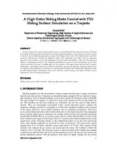
Figure 1. Desired transient response of joint one
Figure 2. Tracking errors with a PD and PID sliding surface, respectively
Figure 3. Torque applied with a PD sliding surface
Figures 3 and 4, respectively. The initial error and PD gains are the same in both cases. A comparison of these two figures suggests that the PID sliding surface provides faster response. However, Figure 2 indicates an overshoot in time response of the controller with the PID sliding surface, which is undesirable in practice. Obviously the overshoot is caused by the ‘energy’ conserved by the integration term. To reduce the overshoot, the ‘energy’ must be released, i.e., the integration should be initiated. This may be done by changing the sliding surface when the tracking error becomes sufficiently small. The procedure can be described in more detail as follows. Int. J. Robust Nonlinear Control, 8, 79—90 (1998)
( 1998 John Wiley & Sons, Ltd.
VARIABLE STRUCTURE CONTROL WITH PID
85
Figure 4. Torque applied with a PID sliding surface
Define a region G "MqJ : DqJ D)d N, where d '0 for i"1, 2, 2 , n. When the state of the i i i i i system is outside G , we apply the control law with the original sliding parameter i t qJ dt#qJQ for DqJ D'd (i"1, 2, 2 , n) (21) s "K qJ #K i i i i i 1Pi i 1Ii 0 The sliding motion starts at a point and the tracking error then approaches the origin by a spiral trajectory. When the states enter the region G , we switch to another definition to initiate the i integration. t qJ dt#qJQ for DqJ D)d (i"1, 2, 2 , n) (22) s "K qJ #K i i i i i 2Pi i 2Ii 0 where K is selected so that K qJ (t )#qJQ (t )"0, which leads to 2Pi 2Pi i i i i qJQ (t ) (23) K " i i 2Pi d i Here t is the time when the trajectory enters the region G . To ensure s (t #)"s (t !) so that the i i i i i i switching variables are continuous at time t , the integral term is initiated as i ti` s (t !) qJ dt" i i for i"1, 2, 2 , n (24) i K 0 2Ii This approach ensures that integration is initiated only when the tracking error enters into the region G . Hence, large overshoots due to the large initial errors can be avoided. The transient i error resulting from such ‘composite’ sliding surface control is shown in Figure 5. The graph demonstrates a fast response with little overshoot. Figure 6 shows the corresponding control torque.
P
P
K K
P
Remark Figures 2 and 5 also demonstrate another advantage of the PID sliding surface. When a boundary layer is inserted into the discontinuous control law in order to alleviate the chattering, the controller with an ordinary PD sliding surface will have steady-state tracking error. With an integration term, however, the steady-state tracking error may be ultimately filtered out. ( 1998 John Wiley & Sons, Ltd.
Int. J. Robust Nonlinear Control, 8, 79—90 (1998)
86
YURY STEPANENKO, YONG CAO AND CHUN-YI SU
Figure 5. Tracking error with a switching sliding surface
Figure 6. Torque applied with a switching sliding surface
3. ADAPTIVE VSC SCHEME The control law (13) requires the parameter a to satisfy a*n2@pEhE . It is very desirable to p estimate this parameter on-line so that none of the knowledge of the robotic system is required for trajectory tracking. The result is given by the following theorem. Theorem 3 Consider the robotic system (1) with the switching surface (2), the tracking error qJ will be globally asymptotically stable by applying the following control law q"!Ks!aJ and the adaptation law
E½E ps EsE p
(25)
a80"!b2a8#cE½E · EsE p p Qb"!K b b where K3RnCn is a positive definite matrix, c and K are arbitrary positive constants. b Int. J. Robust Nonlinear Control, 8, 79—90 (1998)
(26) (27)
( 1998 John Wiley & Sons, Ltd.
VARIABLE STRUCTURE CONTROL WITH PID
87
Proof. Consider a Lyapunov function candidate
C
A
1 K~1 »" sTHs#n~2@p c~1 /2# b aˆ 2b2 4 2
BD
(28)
where /"a8!aˆ is the parameter estimation error, and aˆ "n2@pEhE is a constant scalar, defined as before. p We have, with reference to (14) »Q )!jsTHs!sTKs!n~2@pEsE · E½E (aJ !n2@pEhE )#n~2@pc~1/(aJQ !cE½E · EsE ) p p p p p K~1 #n~2@pc~1 b aˆ 2bbQ 4 "!jsTHs!sTKs#n~2@pc~1/[!b2(/#aL )]#n~2@pc~1 "!jsTHs!sTKs#n~2@pc~1b2(/2#/aL )!n~2@pc~1
K~1 b aˆ 2(!K b2) b 4
aL 2 b2 4
(29)
A B
aL 2 "!jsTHs!sTKs!n~2@p c~1b2 /# 2 )!jsTHs!sTKs therefore, all variables are bounded, and the switching variable s will converge to zero, and the stability of the switching surface guarantees that the tracking error will also converge to zero. K Remark The control law (25) does not require bounds on unknown parameters. The parameter a8 is estimated on-line using the adaptive algorithm (26) starting from any initial value (for example, zero). The low-pass-filter form of the parameter update law, which makes suitable corrections when the parameter is overestimated, ensures that the parameter a8 is bounded. Similar to the VSC case, the control law (25) is also discontinuous, leading to control chattering. The chatter can be eliminated by using the boundary layer tecnique. The result is stated in the following theorem. Theorem 4 The robotic system (1) with the switching surface (2) is uniformly ultimately bounded (u.u.b.) by applying the control law
G
E½E p s, if EsE E½E 'e p p EsE p q" E½E2 p s, if EsE E½E )e !Ks!aJ p p e ( 1998 John Wiley & Sons, Ltd.
!Ks!aJ
(30)
Int. J. Robust Nonlinear Control, 8, 79—90 (1998)
88
YURY STEPANENKO, YONG CAO AND CHUN-YI SU
and the adaptation law a80"!cpa8#cEsE E½E p p where K3RnCn is a positive definite matrix, c and p are arbitrary positive constants.
(31)
Proof. Choose the Lyapunov function candidate as »"1 [sTHs#n~2@p c~1/2] 2 where / is defined in equation (28). If E½E EsE 'e, one has p p E½E p s #EsE · E½E EhE #n~2@pc~1/aJQ »Q )!jsTHs!sTKs#sT !aJ p p p EsE p "!jsTHs!sTKs!n~2@p p/aJ
A
B
"!jsTHs!sTKs!n~2@pp/2!n~2@pp/aL
(32)
"!jsTHs!sTKs!1 n~2@pp/2!1 n~2@pp(/!a)2#1 n~2@p paL 2 2 2 2 )!jsTHs!sTKs!1 n~2@p p/2#f 2 where f"1 n~2@p pa2. 2 If E½E EsE )e, one has p p E½E2 p s #EsE · E½E EhE #n~2@pc~1/aJQ »Q )!jsTHs!sTKs#sT !aJ p p p e
A
B
E½E2 p EsE2#n~2@pEsE · E½E aJ !n~2@pp/aJ "!jsTHs!sTKs!n~2@p aJ p p p e
(33)
when EsE · E½E "e/2, the term !n~2@paJ (E½E2 /e)EsE2#n~2@pEsE · E½E aJ reaches a maxp p p p p p imum value of (e/2) n~2@paJ . Then, we can write as follows: »Q )!jsTHs!sTKs#e n~2@paJ !n~2@pp/aJ 2 "!jsTHs!sTKs#e n~2@paJ !n~2@pp/2!n~2@pp/aJ 2 "!jsTHs!sTKs!1 n~2@pp/2!1 n~2@p p 2 2
CA
B
e2 e 2 ! !aL 2 aJ ! 4p2 2p
D
(34)
)!jsTHs!sTKs!1 n~2@pp/2#m 2 where m"1 n~2@pp(e2/4p2#aL 2). 2 Based on (32) and (34), the uniform ultimately boundedness of the closed-loop system thus follows using the results and terminology in Reference 13. K It should be noted that we also simulated for the adaptive VSC laws (25) and (30), and the results confirmed that the PID sliding surface results in a fast response and a small tracking error; we do not show them for compactness of the paper. Int. J. Robust Nonlinear Control, 8, 79—90 (1998)
( 1998 John Wiley & Sons, Ltd.
89
VARIABLE STRUCTURE CONTROL WITH PID
4. CONCLUSION Variable structure controllers reduce the system dynamics to the motion along the sliding surfaces. Linear sliding surfaces, used in most current designs, are only one possible choice; nonlinear or time-varying surfaces may also be successfully used, and may provide more favourable dynamics. One such possibility, with PID sliding surfaces, is investigated in this paper. We have demonstrated that to include an integral term in the definition of the sliding surface can lead to definite advantages. With a proper definition of the control law, a PID sliding surface can provide faster transient response with little steady-state error. VSC laws developed in the paper are simple, stable and robust with respect to a class of state dependent uncertainties. The algorithms are also simple and suitable for parallel implementation. In the regular version of the controller, only one control parameter should be preselected, while in the adaptive version, the value of this parameter is settled automatically. APPENDIX: SIMULATION EXAMPLE A planar two-link robot arm is used in this paper to illustrate the feasibility of the control algorithms. The model of the robotic manipulator is given by2 H(q)q¨ #C(q, qR )qR #g(q)"q
(35)
where q"[h /]T H "(m #m )r2#m r2#2m r r cos /#J 11 1 2 1 2 2 212 1 H "H "m r2#m r r cos/ 12 21 2 2 2 1 2 H "m r2#J 22 2 2 2
C
C"
!m r r sin //Q !m r r sin /(/Q #hQ ) 2 1 2 2 1 2 m r r sin /hQ 0 2 1 2
D
g1"[(m #m )r cos h#m r cos(h#/)g] 1 2 1 2 2 g2"[m r cos(h#/)g] 2 2 For comparison, the parameter values of the robotic model are chosen as follows: r "1 m, 1
r "0·8 m 2
J "5 kg m2, 1
J "5 kg m2 2
m "0·5 kg, 1
m "6·25 kg 2
which are the same as those in Reference 7. A reference model is chosen to specify the desired behaviour of the robot motion. The reference model is described by q¨ #A qR #A q "Br d 1 d 2 d
where
C
A " 1 ( 1998 John Wiley & Sons, Ltd.
D
C
D
(36)
C D
a 0 a 0 b 11 , A " 21 , B" 1 2 0 a 0 a b 12 22 2
Int. J. Robust Nonlinear Control, 8, 79—90 (1998)
90
YURY STEPANENKO, YONG CAO AND CHUN-YI SU
The parameters used in the simulation are as follows: a "a "a "a "1 11 12 21 22 b "b "1 1 2 rT"[1 1] For this example, we pick the initial displacements and velocities to be h (0)"!1·57, h(0)"!1·47, / (0)"/(0)"0 d d hQ (0)"hQ (0)"/Q (0)"/Q (0)"0 d d Figure 1 shows the desired trajectory. The following figures relate to motions in joint one; the corresponding graphs for joint two are similar and are therefore omitted. From Figure 2 to Figure 6, we use the VSC law (17), where K"10I, a"60, j"10, e"0·05, and I3R2C2 is an identity matrix. Figure 2 illustrates the tracking error with PD and PID sliding surfaces (2), where K "5I and K "10I. P I Figure 3 and Figure 4 show the corresponding torque. Figure 5 illustrates the tracking error with PID sliding surfaces (18) and (19) switching at an appropriate time, where K "5I, K "K "10I, d "d "0·001. Figure 6 shows the corresponding torque. 1P 1I 2I 1 2 ACKNOWLEDGEMENTS
The authors wish to thank the reviewers for their helpful suggestions. REFERENCES 1. Slotine, J. J. E. and M. W. Spong, ‘Robust robot control with bounded input torques’, Journal of Robotics Systems, 2(4), 329—352 (1985). 2. Young, K-K. D., ‘Controller design for a manipulator using theory of variable structure systems’, IEEE ¹ransactions on Systems, Man, and Cybernetics, SMC-8(2), 101—109 (1978). 3. Slotine, J. J. E. and S. S. Sastry, ‘Tracking control of non-linear systems using sliding surface, with application to robot manipulators’, International Journal of Control, 38(2), 465—492 (1983). 4. Yeung, K. S. and Y. P. Chen, ‘A new controller design for manipulators using the theory of variable structure systems’, IEEE ¹ransactions on Automatic Control, 33(2), 995—1003 (1988). 5. Chen, Y-F., T. Mita and S. Wakui, ‘A new and simple algorithm for sliding mode trajectory control of the robot arm’, IEEE ¹ransactions on Automatic Control, 35(7), 828—829 (1990). 6. Young, K-K. D., ‘A variable structure model following control design for robotics applications’, IEEE Journal of Robotics and Automation, 4(5), 556—561 (1988). 7. Leung, T-P., Q-J. Zhou, and C-Y. Su, ‘An adaptive variable structure model following control design for robot manipulators’, IEEE ¹ransactions on Automatic Control, 36(3), 347—353 (1991). 8. Chan, S. P. and W. B. Gao, ‘Variable structure model-reaching control strategy for robot manipulators’, Proceedings of IEEE International Conference on Robotics and Automation, 1989, pp. 1504—1508, IEEE, New York. 9. Wijesoma, S. W. and R. J. Richards, ‘Robust trajectory following of robots using computer torque structure with VSSS’, International Journal of Control, 52(4), 935—962 (1990). 10. Pei, H-L. and Q-J. Zhou, ‘Variable structure control of linearizable systems with applications to robot manipulators’, Proceedings of IEEE International Conference on Robotics and Automation, Sacramento, CA, 1991, pp. 522—527, IEEE, New York. 11. Canudas de Wit, C., H. Olsson, K. J. Astrom and P. Lischinsky, ‘A new model for control of systems with friction’, IEEE ¹ransactions on Automatic Control, 40, 419—425 (1995). 12. Vidyasagar, M., Nonlinear Systems Analysis, Prentice-Hall, Englewood Cliffs, NJ, 1993. 13. Corless, M. J. and G. Leitmann, ‘Continuous state feedback guaranteeing uniform ultimate boundedness for uncertain dynamics system’, IEEE ¹ransactions on Automatic Control, 26, 1139—1144 (1981).
.
Int. J. Robust Nonlinear Control, 8, 79—90 (1998)
( 1998 John Wiley & Sons, Ltd.