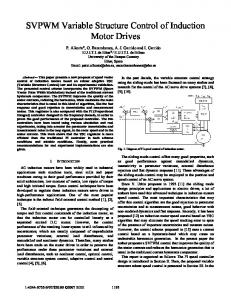
study because of the operational safety and .... During the operation, the designer must consider that the excess ..... Freedom Anthropoid Robot by Driving the.
Variable Structure Systems in Control of Biochemical Processes 1
Oguz H. Dagci, 2 M. Onder Efe, 3 Okyay Kaynak and 4 Xinghuo Yu 1
The Ohio State University, Department of Electrical Engineering Columbus, OH 43210, U.S.A. 2 Carnegie Mellon University, Electrical and Computer Engineering Department Pittsburgh, PA 15213, U.S.A. 3 Bogazici University, Electrical and Electronic Engineering Department Bebek, 80815, Istanbul, TURKEY 4 Central Queensland University, Faculty of Informatics and Communication Rockhampton, QLD 4702, AUSTRALIA ABSTRACT In this study, a bioreactor system is controlled by a three-parameter flexible controller, the parameter adjustment for which is based on a switching strategy using the theoretical framework of Variable Structure Systems (VSS). The simulations performed demonstrate that the controller is able to meet the performance specifications under the existence of observation noise and time varying process parameters. Furthermore, the architectural simplicity of the controller makes the discussed scheme promising for real time applications. 1. INTRODUCTION Control of uncertain systems deserves a careful study because of the operational safety and performance considerations. Existence of noise on the measured quantities and time varying parameters of the plant under control constitute prime difficulties in the design of a suitable controller. Therefore the alleviation of the uncertainties and impreciseness encourages the use of intelligent controllers having the capabilities of fault tolerance and improving the future performance by adjusting the design parameters through a learning process, by which the autonomous behavior is acquired. The integration of VSS theory and the methods of computational intelligence in this sense offers well formulated solutions to ill-posed problems. A prime example of this is the control of biochemical processes. In recent years, tremendous advances have been made in technology and this has affected the practice of process control engineering. With the advances in high speed computing, it is now possible and economically feasible to use complex, model-based control paradigms in practical applications, using advanced strategies derived from adaptive, nonlinear, and robust control theories. The process control problems have also benefited from these developments and various adaptive strategies have
been reported in the literature, with the objective of maintaining the process output close to the desired value in the presence of various uncertainties, including external disturbances, time-varying parameters, and unmodeled dynamics [1]. A recent survey and comparison of various process control configurations can be found in [2]. A more recent tendency in process control is the blending of algorithmic techniques with other elements, such as logic, reasoning and heuristics. Such systems have come to be known as intelligent control systems [3-4]. A host of new control approaches are being used in this respect, based on fuzzy logic, neural networks, evolutionary computing and other techniques adapted from artificial intelligence. In demonstrating the feasibility and efficacy of such approaches in the control of nonlinear processes, process control has been studied in detail by many authors [5-8]. On the other hand, in control engineering practice, stability and robustness are of crucial importance. Because of this, the implementationoriented control engineering expert has always been in pursuit of a design, which provide accuracy as well as insensitivity to environmental disturbances and structural uncertainties. At this point, it must be emphasized that these ambiguities can never be modeled accurately. When the designer tries to minimize the ambiguities by the use of a detailed model, then the design becomes so tedious that its cost increases dramatically. A suitable way of tackling with uncertainties without the use of complicated models is to introduce VSS theory based components into the system structure. Variable Structure Control (VSC) has successfully been applied to a wide variety of systems having uncertainties in the representative system models. The philosophy of the control strategy is simple, being based on two goals. First, the system is forced towards a desired dynamics, second, the system is maintained on that differential geometry. In the literature, the former dynamics is
named the reaching mode, while the latter is called the sliding mode. The control strategy borrows its name from the latter dynamic behavior, and is called Sliding Mode Control (SMC). Numerous contributions to VSS theory have been made during the last two decades, some of them are as follows: Hung [9] has reviewed the control strategy for linear and nonlinear systems. In [9], the switching schemes putting the differential equations into canonical forms and generating simple SMC based controls are considered in detail. Gao [10], applies the SMC scheme to robotic manipulators and discuss the quality of the scheme. In [11-14], it is demonstrated that the theory of VSS can be used for the purpose of learning strategy design. The method discussed in this paper is first proposed by Ramirez for learning in Adaptive Linear Elements (ADALINE) [13]. The paper gives the example of an inverse dynamics identification of a Kapitsa pendulum with a single ADALINE. Yu discusses the same algorithm for ADALINE with the improvement on uncertainty bound adaptation [14]. The strategy adopted in [14] is based on the adaptive adjustment of uncertainty bounds. The methodology discussed in both of these studies assumes that the desired output of the ADALINE structure is available, and the plant is excited in an open loop. Therefore the algorithm discusses in [13-14] is not applicable in feedback control systems without any modification. This paper reports a modification on the method discussed in [13-14] for control applications. The controller is an ADALINE, and the plant is in an ordinary feedback loop. The paper is organized as follows: The second section describes the dynamic model of the plant under control. The next section presents the parameter tuning algorithm. In the fourth section, the simulation results are discussed and the conclusions are presented at the end of the paper. 2. DYNAMIC MODEL OF THE PLANT The techniques employed in modeling the dynamic behavior of continuous flow bioreactors frequently employ the concepts of Monod and Haldane kinetics. Monod kinetics is a simplified form of Haldane kinetics in terms of the unknown parameters appearing nonlinearly. Therefore the design based on the Monod kinetics may violate the performance requirements, while that based on Haldane kinetics may entail the handling of strong nonlinear interdependencies between the variables. The mathematical model of the process studied in this paper is based on the Haldane kinetics. The process is a tank containing a mixture of water, homogeneously mixed cells (microorganisms) and nutrients (substrates), which are the state variables denoted by X and S respectively. The state of the system can be changed by adding influent, whose
substrate concentration is constant and is equal to SF, into the mixture. The volume in the tank is maintained at a constant level by removing tank contents at a rate equal to the incoming rate, which is denoted by D. This rate is called the dilution rate and is the variable by which the bioreactor is controlled. Therefore the system has only one control input, which is the externally supplied influent. The control problem is to maintain the cell and substrate concentrations at the desired levels. The dynamics of the process is described as in (1)-(2). The details of the model can be found in [15].
dX = µ ( S , X ) X − DX , X(0) > 0 dt
(1)
µ (S , X ) X dS =− + ( S F − S ) D , S(0) > 0 dt Y
(2)
where, SF and Y denote the influent substrate concentration and the yield coefficient respectively [16]. µ(S,X) is called the specific growth rate or process growth model. Based on the Haldane kinetics, this quantity is defined as in (3).
µ0S
µ (S , X ) =
(K s + S +
S2 ) KI
(3)
The variable D denotes dilution rate and is the single control input to the process. It is defined as D=F/V where F is the feeding rate and V is the volume of the mixture in the tank [16]. The process parameters µ0, KI and Ks are timevarying variables and are unmeasurable, however their ranges are known. During the operation, the designer must consider that the excess amount of substrate in the mixture causes undesired by-product formation. In order to avoid this, the substrate concentration should not stay above its desired value for a long time. 3. PARAMETER TUNING STRATEGY In this section, it is assumed that the physical constraints on the controller outputs put a bound on adjustable parameter magnitudes ( K < B K ), time derivative of the input vector ( u& < Bu& ) and the time derivative of the desired output of the controller ( D& < B & ). d
Dd
The controller is described in (4), in which the adjustable parameter vector is as described in (5), and the input vector driving the controller is given in (6).
[
D = KT u
K = Kp
Ki
]
Kc T
(4) (5)
u = e
1
t
∫ e(σ )dσ 0
T
(6)
In above, e=S-Sd is the error on the substrate concentration. Defining the error at the output of the controller as in (7), one can consider the Lyapunov function in (8) as a suitable function for describing the learning performance. The time derivative of the function is as given by (9).
ec = D − Dd
1 2 ec 2
(8)
V& = e&c e c
(9)
V =
where
(7)
s=e
T = K& u + K T u& − D& d
(10)
Proposition: For a controller structure described in (4), the adoption of the parameter tuning strategy as in (11) leads to the stability in the sense of Lyapunov.
u K& = − ζ sign (ec ) T u u
(11)
Proof: If (11) is substituted into (10), the error dynamics in (12) is obtained. Using the bounds of the uncertainties mentioned at the beginning of the section leads to (13).
e&c = −ζ sign (ec ) + K T u& − D& d
(
)
V& = −ζ ec + K T u& − D& d ec
)
< B K Bu& + B D& − ζ ec d
(12) (13)
In order to have a negative time derivative for the Lyapunov function in (8), the parameter ζ must satisfy the following relation.
ζ > B K Bu& + B D&
d
(14)
The analysis presented aims to maintain the negative definiteness of the Lyapunov function in (8), which is an instantaneous cost measure. It is apparent that the use of the presented analysis in control applications entails the desired values of the controller outputs. Therefore, for the applications in which the desired signals are available, the method can easily be used without any modification. In this part, parallel to the philosophy of variable structure controller design procedure, a switching function is defined and described by (15). The symbol e seen in (15) is the discrepancy between the
(15)
If one replaces ec of (11) with s of (15), it is possible to prove that the Lyapunov function in (16) is minimized in time and its time derivative is enforced to have negative values due to the adjustment strategy in (11).
V =
e&c = D& − D& d
(
reference state value and observed state value. It should here be noted that since the dynamics under investigation is a first order one, the dimension of the sliding hypersurface is equal to zero, which is apparent from (15).
1 2 s 2
(16)
For this case, the selection of ζ values must be reasonably large for maintaining the sliding motion. The details of the analysis are not included due to the space limit. For an in-depth discussion, the reader is referred to [17]. 4. SIMULATION STUDIES In this part, the performance of the proposed scheme in the control of a bioreactor process modeled with Haldane growth model is investigated. In demonstrating the performance of the overall control system, several difficulties are studied. These are namely the varying plant parameters, observation noise and large initial errors. The values of the process parameters defined in the second section are as follows: Y = 0.5 [g cells /g substrate] SF = 200 [g/l], X0 = 10 [g/l] S0 = 10[g/l], Xd = 99.95 Sd = 0.1 [g/l]. The unknown parameters seen in (3) are set to values given below:
µ0 = 0.35+0.15cos(2πt/10) [l/h] Ks = 0.105 + 0.095sin(2πt/15+3π/2) [g/l] KI = 5+4.975cos(2πt/25) [g/l] During the simulations, in order to show the robustness against disturbances, Gaussian distributed random noise having zero mean and variance equal to 1.64e-6 is added to S(t), which is one of the inputs to the controller. Furthermore, the initial value of S is set to a value which is quite larger than its desired set value. By this means, the ability to compensate the large initial errors can fairly be assessed. During simulations, the bound for the uncertainty denoted by ζ has been set to 1.4. The simulation step size has been selected as 0.01 h and the simulations have been performed under Matlab 5.1 environment.
In Figs. 1 and 2, the time behavior of the substrate concentration and that of cell concentration are illustrated. It is apparent that the substrate concentration reaches its desired value after a sufficiently fast transient regime. Fig. 3 depicts the control signal, which is the dilution rate. One should notice that the signal seen on this plot is smooth enough to allow the discussed scheme for real-time applications. Another important feature of the approach is the bounded evolution in the adjustable parameter space. As seen from Figs. 4-6, the controller parameters evolve in a finite volume. For a detailed treatment of bounded evolution, the reader id referred to [17]. Lastly, in Figs. 7 and 8, the errors in substrate concentration and cell concentration are depicted. It is clear from these figures that the controller meets the desired specifications in terms of the error performance. Based on what has been obtained, the controller suggested in this paper has some advantages over the one discussed in [15]. These can be summarized as follows: -
-
-
-
The method discussed does not require the detailed mathematical model of the plant under control, while most conventional controllers need. The error trend is sufficiently fast, which is clear from Fig. 7. The error in the substrate concentration converges quickly to origin so that by-product formation is considerably reduced. The control input D(t) doesn’t change abruptly in spite of changing variables. This property is important if the reaction time of the actuator, e.g. the control valve, is limited. The observation noise, which is inevitable in practice, has no considerable effect on the performance of the controller.
REFERENCES [1]
[2]
[3]
[4]
[5]
[6]
[7]
[8]
[9] 5. CONCLUSIONS In this paper, the performance of a method based on the adoption of a nonlinear dynamic adjustment strategy in an ADALINE based controller is evaluated in bringing substrate and cell concentrations of a bioreactor process with unknown parameters to the desired levels as fast as possible in a noisy environment. The results show that it works well. What makes the algorithm so attractive in this sense is the fact that the controller possesses only three parameters, the adopted adjustment strategy for which leads to less computational complexity and stability in the Lyapunov sense. Briefly, the controller shows its functionality and flexibility by achieving the given tasks even in the deficiencies caused by the imperfect observations of the state variables, abruptly changing and complex plant dynamics. From these points of view, the method proposed is highly promising in control engineering practice.
[10]
[11]
[12]
[13]
Bastin, G. and D. Dochain, On-Line Estimation and Adaptive Control of Bioreactors, Elesevier, New York, 1990. Zhao, Y. and S. Skogestad, “Comparison of Various Control Configurations for Continuous Bioreactors,” Indust. & Engng. Chem. Res. V.36, pp.697-705, 1997. Passino, K. M., “Intelligent Control for Autonomous Systems,” IEEE Spectrum, v.32, pp.55-62, 1996. Linkens, D. A. and H. O. Nyongesa, "Learning Systems in Intelligent Control: An Appraisal of Fuzzy, Neural and Genetic Algorithm Control Applications,” IEE Proc. Control Theory Appl., v.143, pp.367-386, 1996. Aoyama, A, F. J. Doyle III and V. Venkatasubramanian, “Control - Affine Neural Network Approach for Nonminimum-phase Nonlinear Process Control,” J. Process Control, v.6, pp.17-26, 1996. Bersini H, and V. Gorrini, “A Simplification of the Backpropagation-Through-Time Algorithm for Optimal Neurocontrol,” IEEE Trans. Neural Networks, v.8, pp.437-441, 1997. Zitar, R. A. and M. H. Hassoun, “Neurocontrollers Trained with Rules Extracted by genetic Assisted Reinforcement Learning System,” IEEE Trans. Neural Networks, v.6, pp.859-879, 1995. Efe, M.O., E. Abadoglu and O. Kaynak, “A Novel Analysis and Design of a Neural Network Assisted Nonlinear Controller for a Bioreactor,” Int. Journal of Robust and Nonlinear Control, v.9, pp.799-815, 1999. Hung, J. Y., W. Gao and J. C. Hung, “Variable Structure Control: A Survey,” IEEE Trans. on Industrial Electronics, v.40, no.1, pp.2-22, February 1993. Gao, W., J. C. Hung, “Variable Structure Control of Nonlinear Systems: A New Approach,” IEEE Trans. on Industrial Electronics, v.40, no.1, pp.45-55, February 1993. Parma, G. G., B. R. Menezes and A. P. Braga, “Sliding Mode Algorithm for Training Multilayer Artificial Neural Networks,” Electronics Letters, v.34, no.1, pp. 97-98, January 1998. Efe, M. O., O. Kaynak and B. M. Wilamowski, “Stable Training of Computationally Intelligent Systems By Using Variable Structure Systems Technique,” IEEE Transactions on Industrial Electronics, v.47, no.2, pp.487496, April 2000. Sira-Ramirez, H. and E. Colina-Morles, “A
Sliding Mode Strategy for Adaptive Learning in Adalines,” IEEE Trans. on Circuits and Systems – I: Fundamental Theory and Applications, v.42, no.12, pp.1001-1012, Dec. 1995 Yu, X., M. Zhihong and S. M. M. Rahman, “Adaptive Sliding Mode Approach for Learning in a Feedforward Neural Network,” Neural Computing & Applications, v.7, pp.289-294, 1998. Boskovic, J. D., “Novel Feeding Strategy for Adaptive Control of Bioreactor Processes,” J. Proc. Cont., v.7, pp.209-217, 1997. Boskovic, J. D., “Stable Adaptive Control of a Class of Continuous-Flow Bioreactors,”
[14]
[15]
[16]
AIChE Journal., v.42, pp.176-186, 1996. Efe, M. O., O. Kaynak and X. Yu, “Sliding Mode Control of a Three Degrees of Freedom Anthropoid Robot by Driving the Controller Parameters to an Equivalent Regime,” Trans. of the ASME: Journal of Dynamic Systems, Measurement and Control., v.122, no.4, pp.632-640, December 2000.
[17]
ACKNOWLEDGMENTS This work is supported by Bogazici University Research Fund (Project no: 00A203D)
11 0.45
9
0.4
8
0.35
7
0.3
6
0.25
D (1/h)
S (g/l)
10
5
0.2
4
0.15
3
0.1
2
0.05
1
0
0
-0.05 0
5
10
15
20
25 Time (h)
30
35
40
45
50
Figure 1. The trend in substrate concentration
0
5
10
15
20
25 Time (h)
30
35
40
45
50
Figure 3. Time behavior of the dilution rate, which is the output of the controller
0.155 100 0.15
90 80
0.145 0.14 Gc
60
Kc
X (g/l)
70
0.135
50 0.13
40 30
0.125
20
0.12
10 0.115 0
5
10
15
20
25 Time (h)
30
35
40
45
Figure 2. The trend in cell concentration
50
0
5
10
15
20
25 Time (h)
30
35
40
45
50
Figure 4. Time evolution of the controller parameter (KC)
0.16 10
0.14 0.12
8
0.1 6 eS (g/l)
Gi
Ki
0.08 0.06
4
0.04 2
0.02 0
0
-0.02 0
5
10
15
20
25 Time (h)
30
35
40
45
50
0
Figure 5. Time evolution of the controller parameter (Ki)
5
10
15
20
25 Time (h)
30
35
40
45
50
Figure 7. Error in substrate concentration
-0.28 90 -0.3
80
-0.32
70 60
-0.34
eX (g/l)
Gp
Kp
50
-0.36
40
-0.38
30
-0.4
20 10
-0.42
0 -0.44 0
5
10
15
20
25 Time (h)
30
35
40
45
50
Figure 6. Time evolution of the controller parameter (KP)
0
5
10
15
20
25 Time (h)
30
35
40
Figure 8. Error in cell concentration
45
50