of three single-phase transformers and complex control circuitry. So sometimes it becomes essential to find an alternative, winch is free from constraints posed ...
VARIABLE STRUCTURE CONTROL OF FOUR POLE VOLTAGE SOURCE INVERTER FOR ACTIVE FILTERING OF NONLINEAR LOADS IN 3-PHASE 4-WTOE SYSTEMS
Bhim Singh1, Anuradha2 and D.P.Kothari2 'Electrical Engg. Deptt. 2 Centre for Energy Studies IIT, Hauz Klias, New Delhi 110 011 INDIA
Ambrish Chandra3 GREPCI, Electrical Engg Deptt. Ecole de technoiogie superieure 1100, rue Notredame Oust, Montreal (Quebec) H3C 1K3 CANADA 3
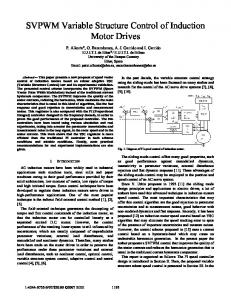
Abstract- This paper presents the analysis of four leg voltage source inverter (VSI) used as an active filter (AF) for reactive power compensation, load balancing, harmonic elimination and neutral current compensation in three-phase four-wire non-linear loads. A variable structure control (VSC) over the average dc bus capacitor of the AF is employed for the control. A hysteresis rule based carrierless pulse width modulation (PWM) current control is employed to generate the gating signals to the switching devices of active filter. A set of three singlephase diode bridge rectifier feeding resistive-capacitive load is used for non-linear loads on the three-phase fourwire system. The merits of the proposed method of control are (1) less complex and reliable active filter configuration (2) fast controller action (3) negligible transients in dc bus voltage of the active filter at die time of instant load changes (4) Gradual convergence of controlled supply currents to new steady state values at the occurrence of abrupt load changes (5) Total harmonic distortion (THD) of the compensated load has been brought well below the standard harmonic specification IEEE-519 limit (6) Neutral current is reduced below 1 % and (7) Simultaneously balances the unbalanced load. Simulated results confirm die validity of die proposed approach for the three-phase (12.5 kW) / two-phase (8.3 kW) /single-phase (4.2 kW) nonlinear loadings. Suggested method is expected to be widely used in future for active filter designs produced for load compensation.
method. Moran et al [5] suggested a mk> point capacitor inverter in series of the load for harmonic current elimination and Peng et al [6] have proposed a generalized instantaneous reactive power theory applicable to threephase four-wire system. Haddad et al have [7] discussed the impact of various parameters on the performance of AF, employing a capacitor mid-point inverter. In three-phase four-wire systems usually reported active filter configurations consist either of a mid point capacitor inverter (die main drawbacks of such filter are the need of two identical, large capacitors and shifting of neutral) or three single-phase VSI, which essentially results in use of three single-phase transformers and complex control circuitry. So sometimes it becomes essential to find an alternative, winch is free from constraints posed by above two configurations. Keeping in mind die relative advantages and disadvantages of filter configurations, a four pole voltage source inverter is chosen as; an active filter with variable structure voltage controller on dc bus of die active filter. The objective of diis paper is to present the analysis of a new control mediod of active filter to compensate non-linear unbalanced load completely, without deviating from sinusoidal nature of supply current even at die time of load disturbances.
I. INTRODUCTION
Figure 1 shows the basic schematic diagram of die proposed filter. The load is a set of diree single-phase diode bridge rectifier feeding resistive capacitive load (RL, CL) widi ac input impedance (Rs, Ls). Due to capacitive loading die uncontrolled rectifier draws nonsinusoidal currents from ac mains. Active filler consists of a four pole VSI using dc bus capacitor as energy storage device with ac input impedance (Rc, LJ. Figure 2 shows control scheme for VSC voltage controller of the proposed AF. The dc bus voltage ( Vdca(n)) of the AF is sensed and compared with its preset reference voltage (Vdc(n)*). The resulting error V e(n) is then processed into VSC voltage controller. If die uniquely defined variable point moves away from die predefined surface then die switching functions vary in a manner to bring back die variable point on die sliding surface, diereby forcing die variable point to stay on die sliding
II. SYSTEM CONFIGURATION AND CONTROL SCHEME
The continuous increase of non-linear loads in various forms cause excessive neutral currents, harmonic injection and reactive power burden in the power system. Numerous methods applied in the active filter and its controller designs have been suggested to deal with diese problems. Lin et al [1] have developed synchronous detection method for reactive power compensation and harmonic elimination in diree-phase four-wire system. Enjeti et al [2] have proposed an active filter using notch filter for neutral current compensation only. Aredes et al [3] extended die instantaneous reactive theory to direephase four-wire system and used a capacitor mid-point inverter. Quinn et al [4] have used a four pole topology for harmonic elimination of currents using a notch fdter 89
„
surface. Resulted output U(n) is taken as amplitude of reference supply currents (Ism*). Reference active filter currents (ica*, icb*, i^*) are obtained by using reference supply currents (isa*, isb*, igc*) and sensed load currents ( i]a, i,b, ilc) . To realize the actual active filter currents (ica, i cb , icc) ia the close proximity of the reference active filter currents, fast acting hysteresis rule based current control is employed. Thereby, ac source supplies only the fundamental active load power and a small component of active power for dc bus voltage regulation.
u
_
sa
v
/v
•
Y
sni'
sa'
a , = v L /V sb
sb
• sm*
u sc
= v IV sc
T
sin
Mfi *•"'
Where Vsm is amplitude of supply voltage and can be computed as : Estimation of reference AF currents Three-phase instantaneous reference currents of the active filter are estimated from reference supply current and sensed load currents as: ^ ' s a * - ' la
Mb
III. ANALYSIS AND MODELLING OF THE SYSTEM
'cc
(8) Hysteresis current controller The AF comprises of an IGBT based four leg voltage source inverter using dc bus capacitor as energy storage element. The switching logic can be formulated on die basis of status of actual current and reference current of active filter. For example :
The considered system is comprised of an ac source, nonlinear load, die AF and its control scheme. All the components of die system are analyzed separately and integrated togedier to develop a comprehensive model to simulate its behaviour. A. Control Scheme
'f ica ** ('ca*"nb) aPPCT switch is OFF and lower switch is ON in the phase "a" leg if i ca > (ica*-hb) upper switch is ON and lower switch is OFF in the phase "a" leg Where hb is the width of hysteresis band. SA I is taken one if upper switch is ON and zero if upper switch is OFF of phase "a" leg. SA2 is taken one if lower switch is ON and zero if lower switch is OFF of phase "a" leg. Similarly, switching logics for the other three legs can be derived. B. Active Filter The active filter is four pole voltage source inverter widi a dc bus capacitor (Cdc) at its output with ac input impedance (Rc, LJ and can be modelled by the following state space equations.
The basic operation of control scheme is explained in the previous section. In this section important governing equations are given sequentially. Estimation of amplitude of supply current The amplitude of die supply current is estimated using VSC over the average dc bus voltage(v(Jca/np of the AF and its reference value (v^,,)*). The dc bus voltage error v e(n) a* t n e nm sampling instant is, v
e(n)~ v dc(n) " vdca(n) = xl
0)
and its derivative is defined as : X
2 = {ve(n) • ve(n-1)} ^
— 1
(2)
Where T is the sampling interval and x1 and x2 are die state variables. In variable structure control, me values of switching functions y, and y2 are defined as follows.
(9)
ys = + l ifzx,>0
(10)
=- 1 ifzx,0
:+(vSc-Vcc)/Lc
(3)
= - 1 ifzx 2 |i/\iwvwVtyVty^ ,iQQ
5,Q
1S)Q
150
20IL
25J3
3J?0
450
7
500 0
00Q
50
I9O
•
50
100
t50
2Q0
250
39O
350
49Q
450
200 250 Time (mSec)
300
350
400
450
1
150
Figure 3 Performance of ihe AF under load change ir..,,M l-o non-linear load (I2.5 kW) 10 2-0 non-linear load (8.3 kW) u, | - c noi.-linear load (4.2 kW) irom lo ihui-Iiiiear I.KKI (4.2 kW) u, 2-« non-linear load (8.3 kW) to 3 - * non-linear load (12.5 kW>
93
wlitudf of *wp VSC control |F«m"
Etttmtt r»f«r«nc« «upl»lw currtntf
i^tftrtnct AF currents
Cat irt«
Ti
TtL
2 VSC control
ich.w
30
30
25
26