1) For Bruker instruments, failure to spin can be due to a dirty shim stack {or lower
(?) ... unit first and to recalibrate the spinning afterwards for Bruker instruments.
“Various possible causes for samples failing to spin in solution probes and potential solutions” Karel D. Klika
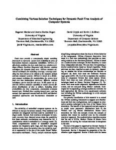
Department of Chemistry, University of Turku, Vatselankatu 2, FIN-20014 Turku, Finland The following causes and possible solutions for samples failing to spin in solution probes have been amassed from responses to an email enquiry submitted to the association of managers of magnetic resonance laboratories (AMMRL). 1) For Bruker instruments, failure to spin can be due to a dirty shim stack {or lower (?) shim stack/assembly or shim matrix assembly or lower barrel or any other name by which the part containing the room-temperature shims goes by} with too much grime and dirt either on the seat (see figure for Bruker systems) or the part of the central bore surrounding the spinner shaft (the “contact area”). For Varian instruments with a different system design, the upper barrel of the internal central-bore assembly is the relevant part.
The most effective remedy is to remove the lower shim stack (Bruker systems)/upper barrel assembly (Varian) and clean it. Alternatively, the seat can, at least in principle, be cleaned by inserting a stick through the top of the magnet (the central bore) attached to the end of which is cloth dampened with alcohol. The contact area of the central bore can be tackled if dirty either from the top or from the bottom, also with a suitable stick and cloth assembly. Obviously when cleaning from the bottom removal of the probe is necessitated, but probe removal is still advised when attempting to clean from the top since this will preclude any potential damage occurring to, or the introduction of any lint, grunge, etc. into, the probe. Entry from the bottom may be difficult due to the limited height of the bottom of the magnet from the floor (use of a collapsible-type stick or a stick attached to a flexible extension may provide a means to do so), whilst entry from the top also seems somewhat problematic in practice in terms of effective cleaning. A number of responders stated that they have tried cleaning the shim stack whilst it remained in the magnet without success (most were not explicit, but the inference was that only entry from the top was tried and no indication was given if only the seat or the contact area or both areas were tackled). Thus, it may be difficult in practice to clean these areas properly by this approach (hence not surprising that many operators resort to shim stack removal), but since it requires minimal effort and is without cost, it can nevertheless be worth trying initially to clean these areas by insertion of a stick and cloth.
Although a non-trivial task, shim stack removal is clearly not beyond many practitioners judging by the number of responses pertaining to this solution. The true cost, however, is not the effort, time, and care required in removal and replacement, but rather the consequences in terms of loss of shim quality and subsequent required adjustment. For low-field, routine instruments (and where sample traffic is heaviest and with less careful users to boot and thus likely to suffer from spinning problems), this is a cost worth bearing, even if the process is done every few years, or yearly, or even twice yearly ! Not much indication was given by the responders in this regards, i.e. loss of shim and attendant effort required to get back to a satisfactory state, other than a few offhand comments that some shimming may be required. Some indication of the risk, however, was clearly evident by the numerous warnings regarding taking note of the exact orientation and positioning of the stack. No indication of the actual field strengths was given either, but it is safe to assume a facilitys’ heavy-use routine instruments are tending towards lower field, hence the problems and risks with regards to shim are of lesser concern. Advisable caveats are that if removing the shim stack, it is best to always turn off the BSMS unit first and to recalibrate the spinning afterwards for Bruker instruments. Most importantly, it is strongly advised to mark the positions of the shim stack assembly. Some shim adjustment, to varying degrees, is required whenever there is lower shim stack displacement, though possibly considerable shim adjustment is consequent for upper shim stack displacement, so this should not be displaced unless absolutely necessary. In other words, because the lower shim stack is fixed to the upper shim stack, if the latter is not moved then there is a reasonable chance to get the lower shim stack back to, or at least close to, its original position. For removal of the upper shim stack, it can be problematic to get it back to its original exact position and hence the lower shim stack will also not be in its exact position and the subsequent shim demands may be considerable. Instructions for removal of the shim stack in Bruker instruments are available online: http://us.brukerbiospin.com/nmr/techsupport/systems/clean.html but are also appended to this file. Needless to say, this guide or other appropriate guide (or the advice of an experienced practitioner) should be carefully read and closely followed during the course of the procedure. For Varian instruments, the system design is different and for MercuryPlus instruments, appropriate instructions copied from an email response are also appended. 2) Blocked air holes that set the spinner in motion (located in the seat of the shim stack in Bruker instruments). Cleaning the air holes with a stick and cloth assembly from the top can be attempted as per above but this may not succeed and probably removal of the shim stack will be necessitated which can allow full access and, in addition to application of a cloth dampened with alcohol, a fine wire can be used to free the holes of dirt. Moreover, injecting some solvent into the large entry holes on the outer rim should allow the liquid flow freely through the fine holes on the seat. Alternatively, higher pressure air can be used to blast free the holes, either with the shim stack out of the magnet or still positioned within it. A higher pressure in the spin system can be attained simply by exchanging the lift and spin air tubes. It is also worth identifying a sample that lifts when turning on the spin function but does not spin (see point 4 vide infra) as this is likely to mean that the air holes are not blocked and perhaps only the contact area of the central bore needs cleaning, which might be accomplished without removal of the shim stack. 3) Calibration of the spinning system. Recalibration of the spinning system (if out of whack) can be a manual procedure involving adjustment of flows etc. or a fully automated procedure taking less than 5 mins. For example, on the BSMS (Bruker systems), simultaneous pressing of the “Y3” and orange-coloured “2nd” keys brings up a flick through menu operated by movement of the “turning knob”. The “sample” option should come up first, and when selected with the orange-coloured “2nd” key, the spin calibration option should come up (again selected using the orange-coloured “2 nd” key). If there is actually no
spinning at all, an error message will be displayed during the automated run calibration and result in termination of the process. Since automatic calibration of the spinning system is a simple thing to do, it is always worth trying. 4) Defective spin sensor or dirty window of the spin sensor. Cleaning of the central bore from and hence possibly the window using a stick and cloth assembly as described above may solve a dirty window problem though this problem is unlikely to occur unless the system is afflicted by copious amounts of dirt. It is thus first worth ascertaining if the sample is actually spinning or not despite the display indicating that it is not due either to the need for spin recalibration or a dirty/faulty reader. A truly spinning sample may be indicated by: a) The lock level which should go up when the spinner is turned on, this can be accentuated by deliberately miss-setting an off-axis shim. The lock level may also go down upon turning on the spinner with a drop implying that the sample is lifted slightly by the pressurised air but is not spinning due to, for example, grime on the wall of the central bore at the contact area. It may be that a slight rise in the lock level can also occur due to a lifting but not spinning sample. b) The wobb (tuning) signal which should be unsteady relative to a static sample; observation of a slight shift upon turning on the spinner whilst viewing the wobb (tuning) signal but with the same steadiness retained indicates the sample has lifted but is not spinning. c) Observing a 1H spectrum and inspecting it for spinning sidebands, again the result can be accentuated by deliberately miss-setting an off-axis shim. Of course, another solution is to peer down the central bore from the top (if appropriate access is available) with the use of a torch to obtain provide definitive proof of spinning. It can also be worth trying to spin the sample without the probe inside the magnet (possible on Bruker) to eliminate the probe as the cause of spin failure. Replacement of the spin sensor located in the upper shim assembly is difficult and may result in considerable demands in reshimming the system, so is a test of last resort. 5) Faulty PNK pneumatics controller board or other electronics. If all efforts to effect a solution fail, then it could be the board controller, which, if another board is on hand or available from another instrument, can be checked by substitution. 6) Shim currents too high. An unexpected cause for spin failure that has been reported is that one or more shims are running at too high a value, e.g. > 10,000 units, leading to the production of excessive heat. The only recourse is to re-shim the probe and reduce the values down to more manageable levels. 7) Deformed spinners. The obvious solution is to replace the bent-out-of-shape spinners, but problems arising due to very slight (and quite undetectable by sight) warping may be accentuated by the build up of grime and dirt, in which case the purchase of new spinners can at least be delayed by cleaning the seat and the central bore in particular as described above. 8) Dirty spinners. The build up of dirt on spinners may be very difficult to discern and recommendations include washing the spinners with soap and water followed by a rinsing with copious amounts of distilled water or wiping the flange and the spinner shaft with cloth/tissue dampened with alcohol. 9) Worn or faded black/white labels on the spinners. It should be self-evident if this is a problem by use of a spinner in good condition. The problem can often be simply corrected by the use of a black marker pen or replacement of the label altogether.
10) Reduced air pressure or flow (due to underperforming compressor, kinked lines, regulator turned down, etc.). Checking the air pressure and even the actual flows using a bubble gauge can identify this problem for appropriate attention. Needle valves (as used in Bruker Avance series) are particular points prone to clogging due to a poor quality air supply and may need to be cleaned to solve the problem, either by blowing high pressure air through them, disassembling them as much as possible and cleaning, or by opening them up as much as possible to allow more gas to pass through at lower head pressure. The build up of oil and other dirt matter from insufficiently clean pressurised air requires cleaning of the system as described above in addition to due attention to obtaining a suitably clean air supply. Since it may take a long time for the dirt or oil to work its way through the system, the problem of dirt can persist for some time afterwards. If the air supply is not sufficiently dry, spinning during low temperature runs can also be inhibited due to the formation of ice on the seat. By far and away the number one cause for spinning problems seems to be a dirty shim stack as evidenced by the number of responders alerting to such. This seems to be something that both Bruker and Varian instruments are susceptible to. The recommendation by many operators is to remove the stack and clean it. This is a major operation, though certainly within the capabilities of most operators, but it is not without its risks even if done correctly. The major concern is disruption of the shims, particularly the off-axis ones, since it is very difficult to get the shim stack back in precisely the same position. Thus, varying degrees of shimming toil may result after this operation (some responders alluded to this risk, others did not or were somewhat casual about it). However, mostly it was not identified what precisely might be the likely source of the problem the seat, the central shaft, or the air holes being clogged. If the stack is removed, it doesn’t matter, one cleans all, but it may be that removal of the stack can be avoided by trying other simpler options first though obviously removal of the shim stack allows unparalleled and easy access and one can inspect the progress of the work and the final result. Laboratory hygiene Clearly it is highly beneficial if users have clean tubes and clean hands, and this includes hands free from talcum powder originating from gloves. Any dirt on the tubes obviously represents a significant danger for the probe, but the transference to the spinner and the rest of the system can result in spin failure though the former consideration is of much greater concern. In relation to the NMR tubes, some labs demand that the tubes be cleaned with a tissue soaked in acetone or ethanol followed by wiping dry with a clean tissue, this seems excessive (though no doubt will extend the length of time it takes for grime to build up), and this may be before and/or after insertion into the spinner. Most labs though seem only to require that the tube be wiped down vigorously with a clean but dry tissue left handily by on the bench (and only periodically changed). In the latter case the notion is generally that the tubes are brought to the NMR lab already clean on the outside. For the labelling of NMR samples, writing on the NMR tubes is not a good idea, the writing easily gets rubbed off or obscured with obvious ensuing problems, but also, the ink ends up as gunk that makes it way into the magnet system with eventual undesirable consequences. So to avoid this, it is best not to write on the tubes. The exception is if there is enamelled white space whereby use of indelible ink seems to be pretty resistant and also the writing is contained near the top of the tube and quite obvious where it is so it is not affected by rubbing the tube clean prior to insertion in the magnet. Paper labels are a better option (a strip of paper say, 3 10 cm, with holes made by an A4size punch for a ring binder, is ideal), and they hold a lot more information which is legible though there is always the chance of mixing labels (but at least one never forgets what is in the magnet as opposed to when the labels are only on the tubes). Tubes can also be safely marked, if not preferably on any enamelled white space, then on the plastic top itself if confusion is a concern. Sticky labels, sticky tape or parafilm are all best avoided completely as the gum tends to end up in the probe and accumulate with time.
Additional caveats 1) To possibly avoid unnecessary toil, all trivial solutions should perhaps be tried first before resigning one’s self to removal of the shim stack. 2) Regarding solvents, acetone should be ok (any cloth should be dampened with solvent, not overtly dripping), and this is echoed Bruker. However, some operators are adamant that alcohol only should be used to avoid damage to O-rings or the window of the spin sensor and thus it is better to simply abide by this. 3) It is worth keeping aside a pristine spinner or two, both for those occasions when one wants to spin and trouble arises, but also to help identify the source of the problem, e.g. spinner holes/seat vs. central bore. 5) It is advisable to always use VT air when the instrument is in use (thus to have positive pressure at the open end of the top of the magnet, this will also happen whilst spinning the sample) and to have the magnet capped when not in use to avoid the accumulation of dust within the magnet. Acknowledgment To all those respondents who replied to an email enquiry submitted to AMMRL with suggestions, advice, and offers of assistance. Appendix For Varian MercuryPlus instruments, instructions (copied from one email response) are as follows: Remove the quick couplings for the eject, bearing and spinning air tubes on the circular top flange. Disconnect the spinning sensor plug, then loosen the two vertical screws (they can be loosened by hand). Remove the upper barrel, including the circular plate with the two screws, and keep the plastic tubings nicely wound around the outside of the central tube. To clean the seat of the spinner, you have to remove the thicker end piece from the aluminum tube. This is best done by two people: One holds the circular plate and the end-piece (with the spinner seat; the one to which the plastic tubing and the cable for the spinning sensor are attached at the lower end) in a fixed position relative to each other and keeps the plate at a right angle to the tube, the other turns the central tube, which is tightened into the end-piece with a fine thread (and goes through an O-ring in the circular plate, which causes some resistance to turning) counter-clockwise. If you have never done this before, it might need some force to get it unscrewed initially). This way, you do not untangle the plastic tubes. You can’t detach the end piece completely because the spinner sensor photocell is soldered to the white cable. However, you have enough leeway to be able to clean the inner part of the spinner seat block with Kimwipes and a non aggressive solvent such as isopropanol. Then re-attach the end piece to the tube again using the same procedure with two people holding and turning, screwing the fine threaded end into the end-piece. Before re-inserting the whole thing back into the magnet, make sure that the three PVC tubes and the white cable are tightly wound around the central tube without crossing each other. Only this way will you be able to insert the whole upper barrel into the magnet again. Fix the circular plate to the magnet top flange with the two screws, then push the central tube down until it touches the lower barrel while gently turning it clockwise (to keep the tubing wrapped tightly around the central tube, although you do not see them, of course), and then finally reconnect the three quick couplings to the air supplies. Instructions for Bruker instruments are biospin.com/nmr/techsupport/systems/clean.html):
as
follows
(or
see:
http://us.bruker-