Vector Quantization Based Data Selection for Hand-Eye Calibration Jochen Schmidt, Florian Vogt∗ , and Heinrich Niemann Lehrstuhl f¨ur Mustererkennung, Universit¨at Erlangen-N¨urnberg Martensstraße 3, 91058 Erlangen, Germany Email:
[email protected]
Abstract The paper presents a new vector quantization based approach for selecting well-suited data for hand-eye calibration from a given sequence of hand and eye movements. Data selection is essential if control of the movements used for calibration is not possible, especially when using continuously recorded data. The new algorithm is compared to another method for data selection as well as to the processing of subsequent movements. Experimental results on real and synthetic data sets show the superior performance of the new approach with respect to calibration errors and computation time. Real data has been obtained from an optical tracking system and a camera mounted on an endoscope, the goal being the reconstruction of medical light fields.
1
Introduction
This paper addresses the problem of selecting data that is well-suited for hand-eye calibration. Handeye calibration algorithms [9, 10, 6, 3] solve the following problem that originated in the robotics community: Given a robot arm and a camera mounted on that arm, compute the rigid transformation from arm to camera (hand-eye transformation). Knowledge of this transformation is necessary, because the pose of the robot arm is usually provided by the robot itself, while the pose of the camera is unknown but needed for visual guidance of the arm. However, if the hand-eye transformation is known the camera pose can be computed directly from the pose data provided by the robot. A problem that is common to all hand-eye calibration algorithms is that the quality of the result is highly dependent on the data used for computing ∗ This work was partially funded by the Deutsche Forschungsgemeinschaft (DFG) under grant SFB 603/TP B6. Only the authors are responsible for the content.
VMV 2004
the unknown transformation. The usual approach for solving this problem is to use robot movements that already take the restrictions on the data into account, which means that the movement has to be planned before recording. Suggestions how this can be achieved were already given in one of the original publications on hand-eye calibration [10]. In situations where planning such a well-suited movement is not possible (e. g., due to constraints on the available space) or cannot be controlled well (e. g., when using a hand-held camera), methods for data selection are required in order to get high-quality calibration results, since the usage of movements in temporal order more often than not is a bad choice, as we will show in this article. One such data selection method was already published in [8]. This approach has some drawbacks, however, the main one being computation time; it will be shortly revisited previous to the new method described in this paper, which is based on vector quantization and gives very good results in only a small fraction of the time needed when using the algorithm of [8]. Hand-eye calibration gets more and more interesting for applications where similar problems arise, but which are not directly related to robotics. Instead of a robot we used an optical tracking system that provides hand data, and a camera, where the camera poses (eye) were computed using a calibration pattern. The camera may in general be an arbitrary hand-held video camera. For our application—the reconstruction of high-quality medical light fields [11]—we used an endoscope with a rigidly mounted CCD camera. The endoscope is moved by hand, its pose is determined by the optical tracking system. More details on this system will follow in the experiments section. The hand-eye transformation has to be estimated every time when the camera head is mounted anew on the endoscope optics, which is done before each operation because the endoscope has to be sterilized. This Stanford, USA, November 16–18, 2004
requires an algorithm that works automatically and fast with a minimum of human interaction. The paper is structured as follows: After an introduction to hand-eye calibration in Sect. 2 we will motivate the necessity of data selection for handeye calibration in Sect. 3. Section 4 gives a short review of the algorithm published in [8] and describes the new approach in detail. Experimental results are presented in Sect. 5.
2
Thus, the rotational part of the hand-eye transformation can be determined first, and, after inserting it into the second equation, the translational part can be computed. This is the way hand-eye calibration is done, e. g., in [9, 10, 12, 2]. Different parameterizations of rotation have been applied. The original works of [9, 10] use the axis/angle representation, quaternions were used by [2, 6], and dual quaternions were introduced by [3, 4]. In contrast to the former approaches, it was suggested in [1] that rotation and translation should be solved for simultaneously and not separately. This approach is also followed in [6], where a non-linear optimization of rotation and translation is done. For our experiments we used the dual quaternion algorithm of Daniilidis [3, 4] to solve (4) and (5). Note, however, that our data selection approach described in this paper does not depend on that special method, but can be used with an arbitrary hand-eye calibration algorithm. In the following we will often refer to the axis/angle representation of rotations, and therefore give a short overview over this parameterization here: An arbitrary rotation R ∈ IR3×3 can be represented as a rotation about one axis r ∈ IR3 by the angle θ. Since only the direction of the rotation axis r is of importance, r has only two degrees of freedom. Hence axis and angle can be combined into a single vector ω, its direction giving the rotation axis and its length the rotation angle: ω . (6) θ = |ω|, r= |ω|
Hand-Eye Calibration
The first hand-eye calibration methods were published by Shiu and Ahmad [9], and Tsai and Lenz [10]. An early comparison of the methods available at that time was given in [12]. The hand-eye calibration problem was formulated in [9] as a matrix equation of the form T E T HE = T HE T H
(1)
,
where Tχ =
„
Rχ 03 T
tχ 1
«
, χ ∈ {H, E, HE}
.
(2)
T H is the robot arm (hand) movement, T E the camera (eye) movement, and T HE is the unknown handeye transformation, i. e. the transformation from gripper to camera1 . All transformations T χ are described by a 3 × 3 rotation matrix Rχ and a 3-D translation vector tχ . Equation (1) can be directly derived from the following diagram: T HE Hj − −−− −→ x ? T H?
Ej x ? ?T E
Axis and angle can be computed from the Eigenvectors and Eigen-values of R: r is the Eigenvector corresponding to the Eigen-value 1, the angle θ can be computed from one of the remaining two conjugate complex Eigen-values of the form cos θ ± i sin θ. Details can be found, e. g., in [9, 5]. This representation is not unique since a rotation about an axis r by an angle θ is the same as a rotation about the axis −r by the angle 360◦ − θ. The axis is not defined when the angle is 0◦ .
(3)
T HE Hi − −−− −→ E i
H i and H j denote the gripper poses, E i and E j the camera poses at times i, j. The usual way to solve (1) is to split it into two separate equations, one that contains only rotation, and a second one that contains rotation and translation:
(RE − I 3×3 )tHE = RHE tH − tE
3
(4)
RE RHE = RHE RH .
Robustness
This section describes how the numerical stability of hand-eye calibration can be increased by selecting the data used for calibration appropriately. Critical factors and criteria for improving the accuracy of hand-eye calibration were already given
(5)
1 Note that in some publications T HE is the transformation from camera to gripper. The other formulation is used here, because in an application usually the gripper coordinates are known while the camera coordinates are unknown.
666
in one of the first publications on that topic [10]. One of the main points is that computing RHE and tHE is in general only possible if at least two relative movements with non-parallel rotation axes are available. Therefore, one criterion for data selection is the non-parallelism of the rotation axes. The positive influence of non-parallel axes on the numerical conditioning—and thus robustness—of the linear system of equations that has to be solved when the dual quaternion algorithm is used was already shown in [8]. Additionally, there is an influence of the rotation angle on the errors in rotation and translation: The larger the rotation angles used, the less the errors [10]. Note that ‘large’ means ‘close to 90◦ ’, because for angles near to zero the rotation axis is not well-defined, while for 180◦ singularities in handeye calibration arise (these are exactly the cases where R has multiple real Eigen-values) [9, 3]. The usual way to fulfill the data requirements (especially non-parallel rotation axes) in robot handeye calibration is to use a calibration setup where the different positions of the gripper were chosen such that the data is well-suited for calibration. Such a setup is described, e. g., in [10]. If a movement according to the requirements cannot be done, e. g., because a hand-held camera is used, or because of lack of space for such a movement, the available data should be used in an optimal way. When a video camera is used images are normally taken continuously, which means that translation and rotation of subsequent frames are similar and the rotation axes are not very different, thus making a processing of the frames in temporal order suboptimal.
4
subsequent frames differ only slightly; therefore it is often disadvantageous to process the data in temporal order. Therefore a data selection step should be performed before hand-eye calibration instead. The main question is what data, i. e. which relative movements, should be used for the data selection described in the following sections. Surely one could just use the relative movements from one frame to the next, and so on. Actually, this cannot be recommended since a lot of information that is contained in the input data would be wasted. Therefore, it is proposed here (and also in [8]) to compute all possible relative movements instead, and use these as input for the following steps. Note that we distinguish between camera poses and relative movements, a relative movement being the transformation between two camera poses. For Nt input frames (= camera poses), the total number of all relative movements is Nrel = (Nt − 1)Nt /2, i. e. the time complexity equals O(Nt 2 ). Experiments showed that this pre-processing step is actually only a matter of seconds even for hundreds of frames. In the following, relative movements will be denoted by Ri , ti where i = 0, . . . , Nrel − 1. As described in Sect. 2, the rotation matrix Ri can be represented as rotation axis r i and rotation angle θ i . Before selecting the movements using one of the following methods, a pre-selection of those relative movements is done where the rotation angles θi are higher than a given threshold θt and less than 180◦ − θt , or higher than 180◦ + θt and less than 360◦ − θt (cf. Sect. 3). The second interval is required since a rotation about an axis r by an angle θ is the same as a rotation about the axis −r by the angle 360◦ − θ.
4.2 Exhaustive Search
Data Selection
This section describes a simple data selection algorithm (published in [8]) that takes into account the angle between rotation axes in order to increase numerical robustness. Movements having ill-suited rotation angles have already been removed during pre-processing (cf. Sect. 4.1 above). This algorithm rates pairs of relative movements (consisting of three camera poses) according to their suitability for hand-eye calibration. The goal is to use the best fraction of pairs for computing the hand-eye transformation. As a rating criterion it is proposed to use the scalar product between the rotation axes of two relative camera movements. This
In the following we describe two methods for data selection: The Exhaustive Search (Sect. 4.2) is a short description of the method used in [8]. Section 4.3 describes the new algorithm, which is based on vector quantization. For both methods a preprocessing step is presented in Sect. 4.1, which should be done before the actual data selection.
4.1 Pre-Processing If a continuous image sequence taken by a video camera is used as input data, the camera poses of 666
yields a value of one for parallel rotation axes and zero for orthogonal axes. Therefore, for all relative movements left after pre-processing, the scalar product of all possible pairs of axes is computed (but not stored, since only the best fraction of movement pairs will be used afterwards). A worst case estimate (if no movements are eliminated during pre-processing w. r. t. angle) of the time complexity of this approach is O(Nt 4 ), Nt being the number of frames of the original image sequence. Note that already O(Nt 2 ) relative movements are used as input data due to the preprocessing described in Sect. 4.1. A drawback of this method is that it is more or less a brute-force approach; it cannot compete in computation time with the vector quantization method presented in the next section. Another problem is that always well-matching pairs of relative movements are selected, where one relative movement may be contained in multiple pairs. The pairs are afterwards used for setting-up a linear system of equations for solving for the hand-eye transformation. Since each relative movement results in one equation, it may happen that one movement is used more than once, leading to two linearly dependent equations, one of them being redundant. Therefore, this approach not only has a relatively high timecomplexity, but also increases the number of equations unnecessarily.
A method which is suited very well for the task at hand is vector quantization [7]. In general, vector quantization works as follows: An arbitrary input vector x ∈ IRn is mapped to a vector of the so-called codebook C, which is a set of Nrs ndimensional vectors that define a partitioning of IRn , i. e. C = {c1 , . . . , cNrs }. Given a distance measure d(·, ·) on vectors in IRn (usually the Euclidean distance), the input vectors are mapped as follows: x 7−→ cκ , where d(x, cκ ) < d(x, ci )
∀i = 1, . . . , Nrs , i 6= κ
.
(7)
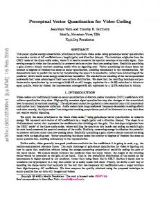
Thus, the entries of the codebook C can be seen as the cluster centers in IRn . For finding the entries of the codebook we use the well-known LBG algorithm (named after the authors Linde, Buzo, and Gray) [7], which is an iterative method that computes the codebook given the desired number of codebook entries. In the following the application of vector quantization to data selection for hand-eye calibration will be discussed. The complete algorithm is shown in Fig. 1. After pre-selection according to rotation angle and normalization of the rotation axes to one, the ambiguity in the axis/angle representation (see above) is resolved by normalizing the axes such that w. l. o. g. the z-coordinate of the rotation axis vector is non-negative by substituting r by −r where necessary. This step assures that similar rotations are actually represented by neighboring vectors in 3-D. Now, the training phase of the vector quantizer, i. e. computation of the codebook vectors, can be started, giving a clustering of the rotation axes. Note that, due to the fact that all axes have norm one, the vectors are not uniformly distributed in space, but lie on the surface of the unit sphere. This is visualized in Fig. 2, where the distribution of the axes vectors and the resulting codebook entries after vector quantization are shown. In many applications these codebook vectors can be directly used for further processing; note that this is not the case for data selection as described here. Codebook vectors are usually computed as the center of gravity (i. e. mean values) of all input vectors belonging to a certain partition. Therefore, a codebook vector does normally not coincide with an element of the input vector set, which in our case means that it cannot be related to an actual relative movement. This is why an additional step has to be
4.3 Vector Quantization Based Algorithm We will now present a data selection algorithm that, in contrast to the exhaustive search method described in Sect. 4.2, does not select pairs of relative movements, but actually selects a globally consistent set of movements that optimizes the non-parallelism criterion. The rotation angle is again taken into consideration using the same pre-selection of relative movements as before, i. e. movements having a small rotation angle are removed. After that pre-selection step, the rotation axes (normalized to one) are used for further processing. The basic idea of the following algorithm is: Given a set of Nrel relative movements represented by their rotation axes, compute a new set of distinct axes consisting of Nrs vectors, where Nrs < Nrel This can be achieved by using a clustering algorithm on the vectors representing axes, which computes a partitioning of the axes vectors. 666
Input: a set of Nrel relative movements consisting of rotation and translation Ri , ti (cf. Sect. 4.1), θt = threshold for pre-selection according to rotation angle (cf. Sect. 4.1), Nrs = number of desired relative movements after data selection is complete. Output: a set of Nrs relative movements consisting of rotation and translation Rκ , tκ . FOR each relative movement i Compute axis r i (norm one) and angle θ i from Ri (cf. Sect. 2) IF θi < θt OR (θi > 180◦ − θt AND θi < 180◦ + θt ) OR θi > 360◦ − θ THEN Rotation angle too small: remove movement i from data set ELSE IF z-coordinate of r i < 0 THEN r i := −ri Compute codebook C = {c1 , . . . , cNrs } of size Nrs using the remaining r i as training vectors FOR each remaining axis r i Classify r i to one of the partitions represented by codebook vector cκ : ri → ri,κ Compute the distance d(r i,κ , cκ ) FOR each codebook entry cκ Determine r κ = rj,κ , where d(r j,κ , cκ ) < d(ri,κ , cκ ) ∀i, j of partition κ, i 6= j Select the relative movement Rκ , tκ that corresponds to r κ as one of the resulting movements Figure 1: Structure chart for vector quantization based data selection algorithm taken in order to get the appropriate data, which is one rotation axis (and the associated relative movement) per partition: For each input element (a rotation axis ri,κ ) of a partition κ, the distance to the codebook vector cκ representing that partition is computed; the selected axis is the one where the distance to the codebook vector d(r i,κ , cκ ) is smallest. The relative movements belonging to the rotation axes selected this way can now be used for hand-eye calibration. In contrast to the method described in the previous section the vector quantization based selection is faster by orders of magnitude, with the additional effect that each movement will actually be used only once, i. e. no redundant equations are introduced.
5
GmbH is employed. It is a typical optical tracking system consisting of two (or more) cameras and a target that is tracked. The target is built from markers that can easily be identified in the images captured by the cameras. In our case spheres with a retro-reflective surface are used. Infrared light simplifies marker identification. The 3-D position of each visible marker is calculated by the tracking system. The knowledge of the geometry of the target then allows to calculate its pose. The hand data of the synthetic data set is based on real pose information obtained from an image sequence using camera calibration. Its eye information was generated artificially using a given ground truth hand-eye transformation. Additionally, the eye poses were disturbed by zero-mean Gaussian noise. In the following, the real data sets are denoted by Real 1 (270 frames) and Real 2 (190 frames), the synthetic one by Synth (108 frames). Table 1 shows errors after hand-eye calibration and computation times for the different methods which have been applied to each data set. Since no ground truth is available when calibrating real data, we cannot give errors between the real handeye transformation and the computed one. It is desirable, however, that an error measure is available which rates the quality of the resulting transformation. Therefore, the following error measure is
Experiments
In the following we will present an experimental evaluation of the vector quantization based data selection algorithm using two real and one synthetic data set. Both real data sets were obtained using an endoscope with a camera mounted on it (the eye), which was moved by hand and calibrated using a calibration pattern. An optical tracking system provides pose data (the hand) of a so-called target that is fixed to the endoscope. The infrared optical tracking system smARTtrack2 by Advanced Realtime 666
lacements
Table 1: Mean errors in rotation and translation of relative eye movements and errors for the hand-eye transformation w. r. t. ground truth for the synthetical data set as well as computation time Data Set/Method Real 1, VQ Real 1, temp Real 1, exhaust Real 2, VQ Real 2, temp Real 2, exhaust Synth, VQ Synth, temp Synth, exhaust Synth, gt, VQ Synth, gt, temp Synth, gt, exhaust
Transl. 13.7% 49.8% 26.2% 7.7% 69% 7.6% 2.3% 235% 2.8% 15% 355% 15%
Rot. (Quat.) 0.0117 0.0252 0.0183 0.00475 0.0120 0.00466 0.00616 0.0769 0.00658 0.00166 0.0776 0.00317
Cardan x 0.82◦ 2.6◦ 1.8◦ 0.17◦ 0.47◦ 0.15◦ 0.35◦ 2.8◦ 0.36◦ 0.0025◦ 8.9◦ 0.22◦
z
0.6 0.4 0.2
0.8 0.6 0.4 0.2 0 −0.4
y
−0.6 −0.8
−0.4
−0.2
0.2
0
Cardan z 0.44◦ 0.60◦ 0.54◦ 0.41◦ 0.59◦ 0.41◦ 0.36◦ 7.3◦ 0.40◦ 0.18◦ 0.41◦ 0.25◦
Time 19.3 sec 174 msec 104 min 14.7 sec 120 msec 41 min 2.88 sec 83 msec 292 sec 2.88 sec 83 msec 292 sec
ments (cf. Sect. 4.1). Note that again it is disadvantageous to use relative movements between subsequent cameras, because the movements will usually be small, which results in large relative errors and thus does not reflect the actual quality of the estimated hand-eye transformation. This is especially true for translation. The data presented in Table 1 were obtained by selecting 100 movements randomly. This process was iterated 100 times, and the resulting errors have been averaged. The errors in translation shown in the table are relative errors in the norm of the translation vector of relative movements. Additionally, we computed the errors in the direction of translation; the results are not shown in the table since the directional errors are highly correlated to the errors in norm. The rotational errors are given using two representations of rotations: The column Rot. (Quat.) shows the mean norm of the difference quaternion√(the highest possible norm difference would be 2), while the following three columns give the mean values of Cardan angles (in degrees, ordering x-, y-, z-axis) of the difference rotation matrix. The rightmost column shows the overall computation time on a Linux PC (Athlon XP2600+), i. e. including preprocessing. For pre-processing we used a threshold of θt = 15◦ . No pre-processing was done for the data in temporal ordering. The codebook sizes were: 600 (Real 1), 1100 (Real 2), and 500 (Synth). The last three rows of Table 1 show the errors for the hand-eye transformation, since for the synthetically generated data set ground truth information was available.
0.8
−0.2
Cardan y 0.75◦ 0.77◦ 0.62◦ 0.21◦ 1.0◦ 0.21◦ 0.35◦ 3.4◦ 0.37◦ 0.059◦ 0.17◦ 0.14◦
0.4
x
Figure 2: Example of a vector quantization result: The rotation axes used as input data are plotted as light small dots, the codebook entries of the vector quantizer as black bold dots. Due to normalization of the axes, all vectors lie on a sphere.
used: After applying the computed hand-eye transformation on the hand data, we get an estimate of the eye movements E 0 .This estimated movement can now be compared to the original eye movement E, which has been obtained from camera calibration: If the hand-eye transformation is correct, the relative movements between single camera positions are equal in E and E 0 . The errors are computed using a set of relative movements selected randomly from the complete set of all possible relative move666
35
0.02
data set 1 data set 2
0.015
25
Error
Error
data set 1 data set 2
30
0.01
20 15
0.005
PSfrag replacements
10
PSfrag replacements 0 0
500
1000
Codebook size
1500
5 0
2000
(a) Real 1 and 2: Error in rotation
500
1000
Codebook size
1500
2000
(b) Real 1 and 2: Error in translation (percent)
−3
6.8
x 10
2.6
Error
Error
6.6 6.4
2.5
2.4
6.2
PSfrag replacements
PSfrag replacements 6 0
500
1000
Codebook size
1500
2000
2.3 0
(c) Synth: Error in rotation
500
1000
Codebook size
1500
2000
(d) Synth: Error in translation (percent)
Figure 3: Mean errors in rotation (quaternion difference) and translation in dependence on codebook size used for vector quantization. Figure 3 shows the influence of the codebook size used for vector quantization on the error in rotation and translation for all three data sets. Additionally, the error w. r. t. the ground truth hand-eye transformation is visualized for the synthetically generated data in Fig. 4. It can be observed that for small codebook sizes the error fluctuations are quite high, but become less when the number of motions used for hand-eye calibration gets higher.
It can clearly be observed that the assumption made at the beginning is valid: using relative movements obtained from subsequent frames of a continuous sequence is very disadvantageous and results in high errors (cf. rows labeled temp). For the exhaustive search (cf. rows labeled exhaust) the errors are comparable to vector quantization for Real 2 and Synth, and higher for Real 1. The computation times of the exhaustive search, however, are unacceptable, especially for data sets with a large number of relative movements; this is a problem because in the application at hand time is a critical factor, since the hand-eye calibration has to be done in the operating room directly before each surgery. In contrast to that the vector quantization based data selection (cf. rows labeled VQ) gives accurate results, while computation time is only a matter of seconds.
6
Conclusion
A new data selection approach for hand-eye calibration was presented which is based on vector quantization. The performance has been compared on real and synthetic data to two other methods: selecting pairs of movements and processing the data 666
8
x 10
−3
30
7
25
Error
Error
6
20
5 4
15
3
PSfrag replacements
PSfrag replacements
2 1 0
500
1000
1500
2000
10 5 0
500
1000
1500
2000
Codebook size Codebook size Figure 4: Errors in hand-eye transformation with respect to ground truth data for the synthetically generated data set Synth in dependence on codebook size used for vector quantization. Left: Rotation (quaternion difference), right: translation. in their temporal ordering. The experiments showed clearly the superior performance of the vector quantization based selection compared to the other methods: Processing data in temporal ordering is very fast, but results in high errors. The results of the exhaustive search are much better, while computation times are unacceptable. The vector quantization approach, however, yields fast and accurate results.
search, 14(3):195–210, 1995. [7] Y. Linde, A. Buzo, and R. Gray. An algorithm for vector quantizer design. IEEE Transactions on Communications, 28(1):84–95, 1980. [8] J. Schmidt, F. Vogt, and H. Niemann. Robust Hand-Eye Calibration of an Endoscopic Surgery Robot Using Dual Quaternions. In B. Michaelis and G. Krel, editors, Pattern Recognition, Proceedings of the 25th DAGM Symposium, Magdeburg, Germany, September 2003, volume 2781 of Lecture Notes in Computer Science, pages 548–556, Berlin, Heidelberg, 2003. Springer. [9] Y. Shiu and S. Ahmad. Calibration of Wrist Mounted Robotic Sensors by Solving Homogeneous Transform Equations of the Form AX = XB. IEEE Trans. on Robotics and Automation, 5(1):16–29, February 1989. [10] R. Y. Tsai and R. K. Lenz. A New Technique for Fully Autonomous and Efficient 3D Robotics Hand/Eye Calibration. IEEE Trans. on Robotics and Automation, 5(3):345–358, June 1989. [11] F. Vogt, S. Kr¨uger, J. Schmidt, D. Paulus, H. Niemann, W. Hohenberger, and C. H. Schick. Light fields for minimal invasive surgery using an endoscope positioning robot. Methods of Information in Medicine, 2004. to appear. [12] C. Wang. Extrinsic calibration of a vision sensor mounted on a robot. IEEE Transactions on Robotics and Automation, 8(2):161–175, 1992.
References [1] H. Chen. A Screw Motion Approach to Uniqueness Analysis of Head–Eye Geometry. In Proc. of CVPR, pages 145–151, Maui, Hawaii, June 1991. [2] J. C. K. Chou and M. Kamel. Finding the Position and Orientation of a Sensor on a Robot Manipulator Using Quaternions. International Journal of Robotics Research, 10(3):240–254, June 1991. [3] K. Daniilidis. Hand-Eye Calibration Using Dual Quaternions. International Journal of Robotics Research, 18:286–298, 1999. [4] K. Daniilidis. Using the Algebra of Dual Quaternions for Motion Alignment. In G. Sommer, editor, Geometric Computing with Clifford Algebras, chapter 20, pages 489– 500. Springer-Verlag, 2001. [5] O. Faugeras. Three–Dimensional Computer Vision: A Geometric Viewpoint. MIT Press, Cambridge, MA, 1993. [6] R. Horaud and F. Dornaika. Hand-Eye Calibration. International Journal of Robotics Re666