2010 International Conference on Intelligent Network and Computing (ICINC 2010)
Vector Shape Classification and Z indexing Khurram Ejaz
Abdul Mateen
Imran Ehsan
Department of Computer Science University of Gujrat Pakistan
[email protected]
Department of Computer Science Federal Urdu University of Arts, Science & Technology, Pakistan
[email protected]
Department of Computer Science Muhammad Ali Jinnah University, Pakistan
[email protected]
Abstract—Vector images are the compact representation of shapes using hard mathematics. Shapes are stored compactly and render efficiently. The advantage of these vector images is that images can be fraction of size as compare to the bitmap. Much work has been done on digital images from different perspective not only to find detail parametric definition of shapes but also their display mechanism. However, this paper is to justify these shapes and then their order of display. Vector shapes consist of different shapes such as line, ellipse, rectangle etc. It is necessary to identify these shapes and their mathematical formulas. We will discuss the shapes with their extracted parametrical identification using formulas and their drawl by using Z index. Keywords-component; Vector; Shape; Vector shape; shape parametric identifications; Z indexing.
I.
INTRODUCTION
Shapes are normally drawings and represented through mathematical formulas, that uses the compact information stored. The elements of shape class are possibly the straight lines, rectangles, squares, polygons, circles and curves. These shape elements can be further divided into sub-shapes, like line shape further divided into poly lines and polygons, rectangle is further divided into square, ellipse further divided into circle and similarly curve is further divides into bazier curves. Mathematical representation of the shape (line, poly line, polygon, circle, curve, Bazier curve, rectangle, and square) is totally dependent on their input parameters. Therefore it is necessary to identify the input parameters first for the drawl of any shape. Each shape generally consists of two things; one is drawl of the shape and second is its fill. In different languages like java, postscript the shapes drawl and shape fill functions are available. Fill color of any shape is mostly consists of RGB (Red, Green, Blue) color model that must be included in mathematical formula. We have surveyed the research related with images and our focus is regarding the shape description and retrieval of shape object. In different tools there are number of shapes and these shapes are stored in the form of classes. It is very necessary to know how shapes are classified and how these classified shapes will be displayed using some sort of mechanism like Z indexing. The research proposed in [8] solved the problem of storage of large map using vector image and vector image is in the form of the scalable vector Graphics(SVG) but authors cannot appropriately define the process of SVG management. They discussed some of the vector shapes but unable to
978-1-4244-8270--2/10/$26.00©2010 IEEE
express the classification of these shapes. They discussed the SVG layer file but again unable to describe how SVG layers form a vector file. If these shape files are using then there is no appropriate mechanism which displays these SVG shapes. In short authors discussed the features but do no define how these features would be accommodated. There is need to classify the vector shapes and their order of display. Edik and Gudukbay [9] considered the number of objects and features like color etc. In their research, shape is also a feature and feature descriptor is written for the shape known as shape feature descriptor. The proposed idea uses Histogram approach and query both are applying on shapes and color features detection in an image. The related work section is ambiguous and specified because shape and color both are discussed at the same time. Authors did not discuss color and shape separately. So that one can easily identifies the parameter of shapes. Secondly shapes are taken with respect to their pixel but authors are unable to express how to handle the shape within the pixel area. As shape parameters are not discussed then how they will be used. The shape detection is major issue in their research but if the shape is not properly drawn then what we can expect which mechanism can be used for the sake of shape object detection. Further paper has been divided in to five sections; section 2 consisting of shape classification, section 3 represent the detail description of each shape, section 4 discuss the Z indexing mechanism, section 5 concludes the paper with future direction. II.
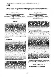
SHAPE CLASSIFICATION
Shape class is a super class and all other shape classes such as line, curve, ellipse, and rectangle are sub-classes. These sub-classes hold the similar attributes of super class with their own some extra properties. So relationship exists between super class and sub-class. This relationship can be seen from top to bottom and bottom to top as shown in Figure 1. To avoid ambiguity, base class (shape) and derived class is taken. It is also possible to treat the base class objects (shape class objects) and derived class objects (line, curve, ellipse, and rectangle objects) similarity and their commonalties are expressed in member of base class. Object of all classes derived from common base class can be treated as object of base class (shape class). Such object has a “is-a” relationship with base class (shape class). It is also an important point that shape class is at level one further divided into number of classes at level two, these derived classes have further derived classes.
V2-1
2010 International Conference on Intelligent Network and Computing (ICINC 2010)
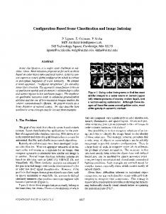
From Figure 2, we can extract the following parameters that are helpful to draw the line shape. L is known as straight line. Line (point 0 0, 100 100) A sequence of connected lines is considered as single object called poly line. The equation or mathematical formula for poly line is as followed: WcPoints.x[1]=50; WcPoints.y[1]=100; WcPoints.x[2]=51; WcPoints.y[2]=101; . . . . WcPoints.x[n] =K1; WcPoints.y[n] =K2;
Figure 1. Classification of shape class in to sub classes.
III.
SHAPE DESCRIPTION
For the sake of shape description, we will give the brief description of each class object and from its formula we will identify its parameters. Basically these parameters are extracted from [1] [8] [11]. A. Line, Polyline & Polygon Line is a path between two specified points. Discrete coordinate positions along line path are calculated from the equation of line or from the slop formula. The equation of line is as followed:
Wcpoint is an array of input coordinate value for line segment. So the parameters which are taken from the above formula are (n, wcpoints), where n is no. of input coordinates parameter. So draw poly line formula will be as followed. Polyline(n,wcpoints); Poly line defines the sequence of (x, y) coordinates which can be written as: Polyline (M= Establish point “150, 50 L 200,100 H250 v50 h50 v40 150, 50)
M = (y2-y1) / (x2-x1) Where x1 = Starting point of line w.r.t. x-axis. y1 = Starting point of y w.r.t. y-axis. x2 = Ending point of line w.r.t. x-axis. y2 = Ending point of line w.r.t y-axis.
From above we have drawn as followed.
In Post Script, there are two types of functions; one function is used to draw the shape and the other for color of the shape. The path of line can be defined by the elements (starting point (open point) and Ending point (close point)). Drawline (int x1, int y1, int x2, int y2); e.g. Drawline (0, 0, 100, 100);
Figure 3. Poly Line by coinciding different lines.
Polygon is closed poly line whose first and last point coincides with each other and forms a regular or irregular polygon. Polygon is specified by the coordinate pairs of x and y arrays. The above polygon can be drawn by following function: Int xpoint={30,200,0,30} Int ypoint={30,30,200,30} Num =4 g.drawpolygon (xpoint,ypoint,num) c=RGB (0, 0, 0) g.f.illcolor(c)
Figure 2. Line draw
Polygon (M= 250, 250 297, 284 275, 340 220, 340 202, 284)
V2-2
2010 International Conference on Intelligent Network and Computing (ICINC 2010)
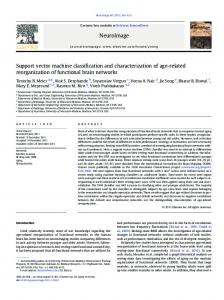
B. Ellipse, Circle, Curve and Bazier Ellipse is an elongated circle and consists of two foci’s. There are two types of ellipses, which can be differentiated by terms Major axis y and X. The ellipse can be described by the following two formulas. First formula is for X major axis and second for Y major axes. (X2/a) + (Y2/b) = 1 (Y2/a) + (X2/b) = 1 The parameter X2/a and Y2/b represents the major and minor axis. The Ellipse will be written in Post Script as:
From above, the main parameters are (Xc, Yc, r), finally Circle will be written as: Circle (points= “Cx 70, Cy=100, r=50 ) Circle is drawn by the drawoval function and can be colored by fillovel function. The left, right, width and height are the parameters which can display circle. Drawoval (topleft, width, height) Filloval (top,left, width, height) In curve a line become steep by using tangent at number of points. The curve can be drawn using following function: Curve (n, wcpoint, id, data list)
EllipsePoints (“Cx= 400 Cy=300, Rx=72, Ry= 50”)
So from the above formula we can define the parameters of an ellipse.
Where n = total number of points Wcpoint = A list of n coordinates position Id = Select desire function Datalist = Non-coordinate values (rx, ry) Bazier curve is a class of curve and completely specified by two end points and two directional points. These points are shown as followed in figure 6.
Figure 4. Ellipse generated foci about F1 and F2.
For X major axis the ellipse function would be as followed: Ellipse ((X2,a),(Y2,b))
Figure 6. Bazier curve with directional point and starting point as well as ending point.
For Y major axis, the ellipse function would be as followed: Ellipse ((Y2,a),(X2,b)) The ellipse can be filled as followed: C = RGB(0,0,0) g.fillellipse(C) The circle is generated by the set of points that all are at given distance (xc, yc) and then can be expressed by Pythagoras theorem. And can be shown as followed.
C. Rectangle & Square A rectangle [2] can be completely described by the opposite coordinates of its opposite corner. It should be cleared that it is possible for rectangle generated program to compute the coordinates from opposite corner from those of centers and one corner. So the input parameter should be opposite coordinates, like top coordinates and bottom coordinates. Function to draw a rectangle is: rect (points = 0 0 , 300 300)
Fillrect (int top, int left, int width, int height)
Figure 5. Calculation of Circle generatd.
Circle by pythagorus theoram. (X-Xc) + (Y-Yc) = r2
A square can be completely described by the opposite coordinates of its opposite corner. It should be cleared that it is possible for square generated program to compute the coordinates from opposite corner from those of centers and one corner. So the input parameter should be coordinates, like top coordinates and bottom coordinates and also height
V2-3
2010 International Conference on Intelligent Network and Computing (ICINC 2010)
and width are there but height and width are equal in size. So function to draw a square is as followed. sqaure (point left,int width, Fillrect(int top, int left,=top, int width, height)height)
descending order, so number 4 will retrieve first; number 3 will retrieve next and so one. Finally index the vector objects first and after that retrieve them in bottom to top order using Z-indexing.
Note that in square height and width are equal in size. Above shapes with respect to their parameters are summarized in table 1. Shape Name Line Polyline Polygon Circle Curve Bazier Curve Ellipse Rectangle Square TABLE I.
Shape Parameters x1, y1, x2, y2 n, wcpoints xpoint,ypoint,num Xc,Yc,R WcPoint,Datalist,id,n C1xC1y,mx1my1,mx2my2,C2xC2y (X2,a),(Y2,b) top, left, width, height top, left, width, height
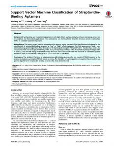
Figure 7. Example diagram
From above diagram we have defined the order of index display. Id 1 2 3 4
PARAMETRIC IDENTIFICATION OF SHAPES.
IV.
Z INDEXING MECHANISM
TABLE II.
Z indexing is a mechanism that is used for indexing of the vector objects or shapes. The order of vector objects drawl would start from bottom to top. The vector objects are line, polyline, polygon, circle, curve, Bazier curves, square and rectangle. These vector objects are combined on the basis of same shape. The same shape vector is called as a layer and each layer is assigned a particular index number. If we have ‘n’ layers there will be ‘n’ index numbers. Now we discuss how Z indexing layered these objects, how the identification number is assigned to each class and how Z indexing retrieves each shape vector. In Figure 7 there are different types of shapes (vector object). These vector objects are placed into their corresponding layers like line layer in which all objects are like line and each layer is assigned by unique value like 1, 2, 3 etc. It is being assigned by the layer that is called as line layer. All polygon types objects are placed into other layer called polygon layer with index value 2. All rectangle type objects are placed into rectangle layer and assigned a unique value 3. Finally all the curve type objects are placed into a layer called curve layer and its index value is 4. The above process expresses the indexing procedure for each shape in Z-indexing. Now we will analyze the retrieval of Z indexing structure for above example. The order of retrieval of the shape would base on their input stream order. From above example line was placed at first position and will retrieve first. Polygon was placed at second and will retrieve at second number. Rectangle was placed thirdly and it will retrieve at number three. Curve was at fourth and final placed. Retrieval is from
Shape Line Polygon Rectangle Curve SHAPE INDEX TABLE
In descriptive way we can see above table as followed. Name of shape Line (3) Polygon (1)
Id 1 2
Rectangle (1)
3
Curve (1)
4
TABLE III.
Layer name Line layer Polygon layer Rectangle layer Curve layer
EXAMPLE INDEX TABLE
The following language script is from Figure 6. Where line identification number is 1 which is already defined in above table, then polygon identification number comes which is declared by identification number 2 and at last third shape which is declared by the identification number as 3, so in following script file the shapes will displayed in their following defined order.
V2-4
line (id =1, current point = 15,100 L 40,52) Polygon(id =2, current point=48 25 v 50 30, 50 30 v, 38 48, 48 40 v, 40,5v , 38,5 h 15 30, 30 15 h 10, 5) Rectangle (id=3, current 5,10 v 10, 50 ) polygon (id=4, 10,52 L 20 52, 20 52 V 20 100, 20 100V 20 52 )
2010 International Conference on Intelligent Network and Computing (ICINC 2010)
V.
CONCLUSION & FUTURE WORK
In this paper we have discussed different vector shapes and their classification with mathematical formulas and identification of different parameters for shape drawl. Available methods for vector images and shapes have been analyzed but previous methods of the vector and their order of drawl do not work well. Therefore we have classified shapes and their order of display. We have discussed the vector shape integration, indexing as well as retrieval by using Z indexing mechanism. We have discussed some issues; however there is lot to do with the vector images. Future research in this area can be done on the integration of different vector files and how to make the vector intelligent and autonomous. Moreover, the developed tools can be enhanced through intelligent strategies and techniques. REFERENCES [1] [2] [3] [4] [5] [6] [7] [8] [9]
Donald Hearn, M Pauline Baker, Computer Graphics C Version, 2nd Edition, 2004. Rafael C, Gonzalez , Richard E. Woods, “Digital image Processing”, 3rd Edition, Pearson Prentice Hall, 2008. httlp://www.XML - Managing Data Exchange-SVG - Wikibooks, collection of open-content textbooks.htm Yvonne Isakowski, Andreas Neumann, “Interactive Topographic Web-Maps Using SVG”, 2003. Special paper on svg\Interactive SVG Map.htm Scalable Vector Graphics (SVG) 1.1 Specification'. 2nd Edition, June 2010. http://www.w3.org/TR/SVG W3C Scalable Vector Graphics (SVG), SVG Conformance Test Suite. http://www.w3.org/Graphics/SVG/Test/ Michael P Peterson, “Topographic Maps With SVG”, 3rd Annual Conference on Scalable Vector Graphics, Tokyo, Japan, 2004 S. Ediz, G. Ugur, U. Ozgur, “A histogram-based approach for objectbased query-by-shape-and-color in image and video databases”, Image Vision Comput, Volume 23(13), Pp. 1170-1180, 2005.
V2-5