VEGA: A Visual Environment for Developing Complex Grid Applications Antonio Congiusta ICAR-CNR Via P. Bucci, 41c 87036 Rende, Italy
[email protected]
Domenico Talia DEIS University of Calabria Via P. Bucci, 41c 87036 Rende, Italy
[email protected]
Abstract Providing high level environments and advanced instruments able to support end users and developers is of main importance to help designers of complex grid applications and explore many of grid related benefits not yet fully exploited. In this paper we present a high-level grid programming environment oriented to data-intensive and knowledge discovery grid applications that share some common features with the software component paradigm. The system we describe here is named VEGA Visual Environment for Grid Applications; its purpose is to provide a unified environment comprising services and functionalities, ranging from information and discovery services to visual design and execution facilities, useful to simplify the design and execution of complex applications by exploiting advantages coming from a grid environment. .
1. Introduction Grids are receiving even more interest by a significant number of scientific, industrial, and economical bodies, thanks to their capability to enable collaborations, even cross-organizational, based on large scale resource sharing and performance orientation. In the last 4-5 years grids researchers and professionals have been concerned with the development of a series of experiments and demonstrations aimed at showing basic grids features and potentials. Large scale grids were deployed to solve computational or data intensive problems as well as to perform complex simulations. Presently, grids are widely recognized as the next generation computing architecture, the natural evolution of the Web towards the delivery of computing power, information, and knowledge. Now, grid community efforts are focused to make that technology robust, reliable, and available to those interested in adopting it. The recent involvement of companies like IBM, Sun, and Microsoft is a clear symptom of the relevance the matter is going to assume in
Paolo Trunfio DEIS University of Calabria Via P. Bucci, 41c 87036 Rende, Italy
[email protected]
the near future. Belong this trend, providing high-level environments and advanced instruments able to support end users and developers, is of main importance to explore many of grid related benefits not yet fully exploited. Most problems addressed by grids are not simply solved through the execution of a specific ad hoc “program”, but often require several software modules, most likely interacting each others, to run separately and/or concurrently over a given set of inputs. Till today not much work has been done to build high-level design facilities for complex grid applications in which many programs and data sets are involved. This class of applications are quite common in several domains, such as knowledge management, computational science, and ebusiness; in addition they share common traits with software component based applications. Software component technology is now a standard part of many software design practices. Microsoft COM and much of .NET [1] are based on component concepts, as well as Enterprise Java Beans [2], another important technology for building large scale e-commerce applications. A software component model is a system for assembling applications from smaller units called components. The system defines a set of rules that specify the precise execution environment provided to each component, the rules of behavior, and special design features components may have. A component is then nothing more than an object (or collection of objects) that obey the rules of the component architecture. A component framework is the software environment that provides the mechanisms to instantiate components, compose and use them to build applications. The software component model can be effectively used in grid applications integrating legacy code and new software modules. In this paper we present a high-level grid programming environment that has some common features with the software component paradigm. The system we discuss here is VEGA - Visual Environment for Grid Applications. VEGA provides a unified environment comprising services and functionalities
ranging from information and discovery services to visual design and execution facilities. VEGA was designed and implemented to support users in the design of dataintensive grid applications as part of the Knowledge Grid [6], a software infrastructure for developing knowledge discovery applications. However its high-level features make it useful in the development of a large class of grid applications. The remainder of the paper is organized as follows. Section 2 presents the main features of VEGA. Section 3 introduces the visual language used to design an application in VEGA. Section 4 illustrates the architecture of the environment and Section 5 goes more deeply into some implementation aspects. Several enhancements and additional features under development are presented in Section 6, where “open issues” are discussed. Section 7 presents a sample application and Section 8 makes a comparison of the system with some of the major related works. Finally, Section 9 concludes the paper.
2. Main features and requirements The main goal of VEGA is to offer a set of visual functionalities that give the users the possibility to design complex software, such as knowledge discovery applications, starting from a view of the present grid status (i.e., available nodes and resources), and composing the different steps inside a structured environment, without having to write submission scripts or resource description files. The high-level features offered by VEGA are intended to provide the user with easy access to grid facilities with a high level of abstraction, in order to leave her/him free to concentrate on the application design process. To fulfill this aim VEGA builds a visual environment based on the component framework concept, by using and enhancing basic services offered by the Knowledge Grid and the Globus Toolkit. To date, a grid user willing to perform a grid application must know and handle a number of detailed information about involved resources (computing nodes, software, data, etc.), like their names and locations, software invocation syntaxes, and so on. This makes the planning and submission of an application a long and annoying work, exposed even to failures due to user mistakes in writing allocation scripts with a given syntax, wrong memory about resources details, etc. As a first feature, VEGA overcomes these difficulties by interacting with the knowledge directory service (KDS) of the Knowledge Grid to know available nodes in a grid and retrieve additional information (metadata) about their published resources. Published resources are those made available for utilization by a grid node owner by means of the insertion of specific entries in the Globus monitoring and discovery service (MDS). So, when a grid
user starts to design its application, she/he needs first of all to obtain from KDS metadata about available nodes and resources. After this step, she/he can select and use all found resources during the application design process (as described in the following). This first feature aims at making available useful information about grid resources, showing the user their basic characteristics and permitting her/him to design an application. The application design facility allows the user to build typical grid applications in an easy, guided, and controlled fashion, having always a global view of the grid status and the overall building application. Surely this is the core functionality of VEGA. To support structured applications, composed of multiple sequential stages, VEGA makes available the workspace concept, and the virtual resource abstraction. Thanks to these entities it is possible to compose applications working on data processed in previous phases even if the execution has not been performed yet (useful in many knowledge discovery applications). Once the application design has been completed, resulting job requests are to be submitted to the proper Globus Resource Allocation Manager (GRAM). VEGA includes in its environment the execution service, which gives the designers the possibility to execute an application and to view its output.
3. A visual language to specify applications A grid-based application is often more complex with respect to a similar one based on classical computing systems. Issues like distribution of software, data, and computers themselves have to be addressed. The availability of computing nodes able to host a given computation is related to strict constraints about performance and platform requirements, as well as specific policies about access to resources, as defined by the related virtual organization [4]. It appears clear, hence, that a structured way to model and express such a variety of constraints and implications is needed. VEGA, rather than devise a set of customized syntactical rules, makes available a visual language to express “relations” among “resources”, and to describe with a graphical representation the overall computation. VEGA provides developers with a set of graphical objects representing different kinds of resources they can select and use to compose an application. In particular, there are three types of graphical objects: • hosts, • software, and • data. Each of these objects represents a physical resource in the grid. The user can insert several instances of the same resource into a workspace of the current project if needed.
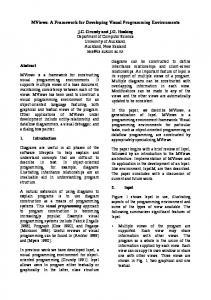
A workspace is thus a working area of the VEGA environment, in which objects representing resources are hosted to form a particular stage of the application. When a resource is inserted in a workspace, a label containing the name of the related physical resource is added to the corresponding graphical object. Several relations, indicating interactions between resources, may exist. Relations are represented in VEGA as graphical links between the resources which they refer to. Through relations it is possible to specify one or more desired actions on resources included in a workspace. In other words it is possible to describe one or more jobs (see Figure 1).
Figure 1. Objects and links in VEGA A common definition of “grid job” states that it is the execution of a given software on a specific grid node, with its input and output parameters/files specified as well. Relations available to describe jobs are: • execution of a given software on a given host, • file transfer, of a certain software or dataset on a specified host • input, (a given dataset as input for a software) and • output (a given file as collector of a software output). The file transfer relation specifies itself a job, as previously defined, since it can be viewed as the execution of a file transfer program which parameters are the file to be moved, the destination host, etc. So, in VEGA a job is a software execution or a file transfer. While introducing relations between resources, some rules must be followed, in order to make the composition have sense. For instance, an execution relation (link) cannot be inserted between a data object and a host object. Moreover, no link can be inserted between objects of the same type. The set of admissible links is listed in Table 1, with enclosed the meaning each one takes in the specific context. Objects refer to specific resources offered by grid nodes included in the deploying project; they can be linked with resources owned by the same node as well as with resources of a different node. In the latter case a staging operation (as provided by the Globus GRAM) is implicitly defined. If, for instance, a software component SW owned by the host H1 is linked with an execute link with a host H2, then the executable associated to SW will be first transferred to H2, and will be deleted from there after the execution.
resource1
resource2
link
meaning
Data
Software
Input
software input
Data
Software
Output
software output
Data
Host
File Transfer
data transfer
Software
Host
File Transfer
software trans.
Software
Host
Execute
software exec.
Table 1. Admissible links between resources A computation is generally composed by a number of different sequential or parallel steps. In VEGA it is possible to distinguish sequential and parallel execution of jobs through the workspace concept. All jobs that can be executed concurrently are to be placed inside the same workspace, whereas to specify a priority relationship, different workspaces have to be used. It is worth to note that when different sets of jobs are placed into different workspaces often they share common data, on which they make different computations. A
C
B A: simple job B: multiple job C: same input for different jobs
Figure 2. Some jobs in the VEGA visual language As an example, let us consider a typical execution of the data mining tool DM-tool on the specific grid node Host_X, taking as input the pre-processed.dat file, and producing as result the file classes.dat. This job (say simple submission) is described in the VEGA visual language by linking the objects representing the resources as showed in Figure 2-A. A multiple submission, that is the simultaneous execution of the same application on more than a grid node, is quite similar to a simple execution, the only exception is that the same software object is linked with more than a host (see Figure 2-B). Similarly, different submissions, i.e. two different software to be executed on different hosts, may share the same dataset, like in Figure 2-C.
4. Architecture This section outlines how the VEGA environment works on top of the Knowledge Grid and the Globus Toolkit, basic relationships and interchanges among these entities are also explained. The Knowledge Grid is a software infrastructure for distributed data mining and extraction of knowledge in grid environments. The Knowledge Grid accomplishes its objectives through the implementation of a set of basic services and high level tools designed to support geographically distributed high-performance knowledge discovery applications. The set of services and functionalities offered by VEGA is composed basically by two categories: design facilities and execution handling. The first ones are concerned with functions for designing and planning a grid application, whereas the others make possible to execute the application. Figure 3 shows hierarchies and some basic interactions between them and the Knowledge Grid and Globus services. In particular, the design facilities make use of the knowledge directory service, implemented by the Knowledge Grid, to discover resources and their properties, whereas basic Globus services are used during the authentication and the execution phases. There are at least four steps a user must follow to execute one or more jobs employing grid resources: • • • •
definition of involved resources and specifications of the relations among them; checking of the planned actions consistency; generation of the job set to be submitted to one or more grid resource allocation managers; execution of the jobs and monitoring of their life cycle.
The job submission procedure in VEGA can be divided in the previous four steps. Figure 4 shows the VEGA software modules implementing them together with the needed data exchanges. The visual composition phase is useful to the user during the application design. It is accomplished by the Graphic Composer software module and its submodules. To design her/his application a user may compose graphical objects representing resources (datasets, software components, computing nodes). These objects are composed through visual facilities, aimed to specify existing relations among them, to form a graphical representation of each job of the entire computation, accordingly with the rules discussed in the previous section. Namely, this task is accomplished by the following sub-modules: Workspace Manager, Object Manager and Resource Manager.
The Resource Manager (RM) is concerned with the browsing of a local cache called task metadata repository (TMR), where metadata about retrieved resources are stored, in order to allow the selection of resources to include in the designing computation. The Resource Manager is divided into two sections, directly showed to the user: the first one contains the list of the chosen computing nodes (hosts); the second one contains the resources belonging to the currently selected host, divided into two categories, data and software, on the basis of the content of associated metadata (see Figure 5). Such a structure gives an overall view of the available hosts and related resources, permitting, at the same time, to include them inside a workspace of the current project.
Figure 3. VEGA overall architecture Additional information about these resources are retrieved through the knowledge directory service, a system able to include customized metadata into the Globus monitoring and discovery service (MDS) LDAP tree, and to delivery them to each user of the grid when requested. Metadata used in the Knowledge Grid are constituted by XML encoded information describing software and data resources. The analysis of the Knowledge Grid information system functioning is out the purposes of this paper (details can be found in [6] and [7]). For what concerned with the operations of the RM, it is enough to know that XML documents specify some resources attributes among which: owner host, file name and related path. The TMR is located on the file system of each node of the Knowledge Grid running VEGA and is organized as a set of directories, one for each host. Each of these directories contains XML documents about resources published by related hosts by using KDS services. A host can publish basically two types of resources, software and data.
selection, un-selection, linking with other objects and deletion from a workspace. All these operations are handled and supervised by the Object Manager. Moreover, it takes care of the links labeling and the setting of their properties and/or attributes, like: file transfer destination path, parameters to be used in the software invocation, etc.. WorkSpace Manager
Host panel
Resource panel
Figure 5. Vega user interface
Figure 4. Vega software modules The Workspace Manager (WM) is given the task of creating and managing workspaces. It maintains an internal representation of the entire computation designed by the user (internal model) and a priority relationship between workspaces, as they constitute a whole computation, in which the workspace sequence represents the planned sequence of tasks to be executed. In addition, it may be possible that some jobs in a given workspace need to operate on resources generated in a previous one; in this case the WM, since these resources aren’t physically available at design time, generates the so called virtual resources, and make them available to subsequent workspaces through the Resource Manager. The Object Manager (OM) copes with the management of the graphical objects associated with the resources chosen by the user to compose an application. Each object is associated with information regarding the resource which it refers to. This information is used during the creation of the internal model of the computation and to the end of generating the execution plan (see below). Objects, as already mentioned in the previous section, are data, software, and hosts. During the composition phase, these objects may be subject to operations such as: insertion in a given workspace, movement inside the owning workspace,
The Consistency Checking phase is needed to obtain a correct and consistent model of the computation. This process is accomplished not only as a checking of a set of requirements after the design phase is completed, but mainly through several interactions with the user while the design is in progress. Regarding the type of consistency checking and the time which it is performed on, two stages can be distinguished: pre-processing and post-processing. The pre-processing takes place simultaneously to the composition of the graphical representation made by the user. It operates in a context sensitive way, detecting situations that may lead to errors and undertaking actions to guide the user towards the right choices. The checking is completed with the postprocessing, nonetheless needed to catch those error situations that are impossible to discover during the preprocessing phase. When the consistency checking is carried out, it is time to parse the model of the computation to generate the execution plan and the specific Resource Specification Language (RSL) script needed for the allocation. The generation of the execution plan is performed by means of the Execution Plan Generator (EPG) module. It parses the internal model of the computation and, on the basis of the properties of links and resources, produces an XML document describing the planned tasks, the so called execution plan. The execution plan describes the computation at a high level, without physical information about resources (identified by metadata references), and
about the status and current availability of such resources. Specific information about the involved resources will be included during the translation into the RSL script. The RSL script is a set of job requests expressed into the Globus Resource Specification Language; it is produced by the RSL Script Generator as a result of a subsequent elaboration on the execution plan. The Execution Manager (EM) permits to start the execution of the application and handles communications between activated jobs and the user. The execution phase makes a direct use of specific GRAM services. To start the execution, a valid proxy of the user authentication on the grid must have been created. The Utilities section contains the Authentication Manager (see Figure 4), which offers a visual facility to create and set up the proxy for accessing grid resources. Finally, the Utilities section comprises a functionality designed to serialize and restore the graphical model of the application.
5. Implementation VEGA was implemented in Java, to guarantee the portability upon different platforms. Namely, the user interface components are all Swing based, whereas the access to Globus services is accomplished by using some of the APIs contained in the Java CoG Kit [5], developed by the Globus Project Team. The Resource Manager offers the so called resource panel, as showed in Figure 5. It is divided into two subsections, one containing hosts and the other one the resources each host own. Hosts showed are those chosen by the user, among ones available in the TMR, to be part of the current application. When a host is selected in the host sub-panel, the RM accesses the corresponding entry in the TMR, scans all metadata and shows the resources owned by this grid node in the resource sub-panel, each in the related category (software or data). To deal with XML documents, the RM makes use of the Xerces Java Parser [8], an open source implementation from Apache Software Foundation of the DOM (the W3C Document Object Model) [9]. Through the RM it is also possible to retrieve information about the status of the resources involved in the current project. For example, the user may query current CPU load and available memory, as well as static information like operating system name, etc. To import a resource in a workspace the user can drag & drop it. When the RM detects the drag-started event, it provides the Object Manager with all the information found in the resource metadata document, so that the graphical object for that resource can be created. The Workspace Manager performs a preliminary analysis of the composing computation, to discover conditions that may originate virtual resources: like the presence of a file transfer operation or the presence of an
output resource generated by a job in the computation. When such a condition holds, the WM generates appropriate metadata and put them in the TMR, marking them as temporary entries (waiting for the real execution of the application). Metadata about virtual resources are homogeneous to ones about “real” resources and can be thus managed by the RM. Temporary entries, created during the design phase, will become permanent if after the design phase the execution is performed and it terminates successfully. Otherwise, if the user exits the working session without executing the application, they will be removed from the TMR. The user interface of the WM is basically constituted by a tabbed pane that allows for selecting the workspace on which to operate (see Figure 5). The WM accomplishes also the task of building the internal model of the computation on the basis of the graphical composition made by the user and constituted by the workspaces sequence. The construction of the internal model takes place together with its graphical definition by the user. The Object Manager can be thought as a “service module”, in fact it hasn’t a specific corresponding element in the user interface and most part of the code implementing it is distributed in several listeners. Java implements the events driven programming paradigm, in which listeners are classes notified of the occurrence of particular events (e.g. mouse and keyboard activities); these classes contain methods to handle such events. The internal model consistency checking ensures that the model to be passed to the Model Analyzer is correct and without inconsistencies, that is, able to represent coherently a grid application. The Model pre-processor operates during the application composition. Its main objective is to prevent the planning of jobs in a wrong or incomplete fashion. To this end, it supervises the links insertion, checking for the right association (see Table 1) between resource types and links. At the end of the design session, the user can compose one or more workspaces. Although the workspaces composition has been guided by the Model pre-processor, there are some ambiguous situations that can be only recognized when the designing phase is over. Main constraints verified by the Model post-processor are: • at least one host must be present in each workspace; • all inserted links must have been labeled (that is, a type for each of them must have been specified); • each software component must be linked with at least one host; • every resource must be linked with at least another one. As previously mentioned, the execution plan is coded in XML and represents the application at a high level of
abstraction; it is generated to make aware the Knowledge Grid Execution Plan Management Service (EPMS) of the computation structure (the formalism is well described in [10]). To generate the execution plan, the EPG analyzes the internal model of the computation to individuate all the jobs planned by the user. The RSL script generation takes place on the basis of the execution plan and the information provided by metadata referred in it. All jobs in the execution plan are translated into RSL job requests, assigning proper values to RSL attributes. Details about RSL tags can be found in [11]. Main attributes used by VEGA are: • resourceManagerContact, the node to which the request is to be submitted; • executable, path and name of the program to run; • arguments, a set of arguments to be passed to the program through the command line. • stdout, a file to witch redirect the program standard output (if required by the user). Computation elements in the execution plan are translated into job requests specifying the execution of a given executable with some inputs and outputs; as already mentioned, all details on executable inputs and outputs are retrieved in the referred XML files. DataTransfer elements are processed using as executable the program globus-url-copy, with source and destination parameters as indicated in the execution plan. In this way all file transfer operations are carried out using the GridFTP protocol [12]. To reflect the workspace sequence in the jobs execution, job requests present in different workspaces are placed in separated RSL files and will be submitted to execution in strict sequence by the Execution Manager. After the RSL script files are generated, they will be executed trough the globusrun command. It is invoked by the VEGA Execution Manager taking into consideration each script file and allocating a new process (executing the globusrun command) on the machine which the user is working on. In addition, to provide the user with a feedback about the computation execution, standard output and error streams of that process are redirected to the EM and showed as well.
In a varying and discontinuous environment such as a grid, users’ requests cannot be always deterministic in all details. It would be very difficult, and flexibility loss leading, to pretend the user to specify all details about resources involved in a computation. Therefore, when the user doesn’t worry about which will be the target machine for a given job, provided that it is able to satisfy a set of expressed requirements, it should be up to the system to find a suitable host and to assign it the job execution. This could be also a powerful mechanism that could give the user the possibility to design applications independent from the particular grid on which they will be executed, hence, reusable upon different grid systems and over the time. To this purpose the concept of “abstract resources” is going to be introduced in VEGA, This approach allows for specifying resources by means of constraints (i.e., required main memory, disk space, CPU speed, operating system version, etc.). In addition, a meta-scheduler will also be included to instantiate abstract resources. After the appropriate matching of abstract resources with physical ones and a possible optimization phase, on the basis of the application structured layout, the system can submit for the execution all the jobs defined in the application design.
7. Sample application This section presents a sample application through which the main features and potentials of VEGA will be better explored. At the same time a practical use of VEGA will be showed and some problems that may arise in this kind of applications will be analyzed. The chosen case consists of a grid-enabled version of a knowledge discovery application.
6. Open issues In the current VEGA implementation workspaces can be connected in a pipelined fashion. This may represent a limitation of the capacity to represent some computation patterns, even if complex patterns can be designed inside a single workspace. To make more flexible the way of composing workspaces, the sequential workspace composition will be replaced by an acyclic graph model.
Figure 6: Distributed bank scoring application
7.1 Distributed bank scoring This example takes into consideration the evaluation process done by banks when approving a loan. Loan officers must be able to identify potential credit risks and decide whether grant the money, and, in that case, the amount of the loan. Usually this is accomplished by evaluating information about people to whom the institution previously loaned money (such as debt level,
as either a graphical tree or a set of text rules that can predict (classify) each applicant as a good or bad credit risk. The training process that creates the decision tree is usually called induction. One important characteristic of the tree splitting algorithm is that it is greedy. Greedy algorithms make decisions locally rather than globally. When deciding on a split at a particular node, a greedy algorithm does not look forward in the tree to see if another decision would produce a better overall result.
Figure 7. Distributed bank scoring: workspace 1 and 2 income level, marital status, etc.). Let us consider the case of three banks whose purpose is to join their efforts and extract a loan-scoring prediction model, based on the information each of them own about their clients. Since preserving client’s privacy is a must for credit institutes, the treatment of this information by third parts is often prohibited or subject to restrictions. To overcome this problem the banks decide to make the computations locally, at each of the three sites, and to transfer on a centralized location only the obtained models. In this way, no sensible information has to be accessed by unauthorized organizations, but only the data models have to be shared. Privacy commitments are thus assured, because the data models are constituted by coded information about aggregated data. When a decision is based on several factors, a decision tree can help identify which factors to consider and how each factor has historically been associated with different outcomes of the decision. A decision tree creates a model
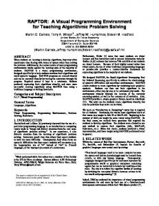
This allows for creating partial models from subsets of the data that can be then joined into a global model. Prior to integrating any decision tree into a business process as a predictor, a test and a validation of the model using an independent dataset is generally performed. Once accuracy has been measured on an independent dataset and is determined to be acceptable, the tree (or a set of production rules) is ready to be used as a predictor. The testing phase in this example is done after the combination of the three models. To summarize, the entire application is composed of two main phases (see Figure 6 for a graphical schema): the induction of the decision trees, performed locally at each of the three banks, and the models combination and validation operated at one of the three sites after the others models have been produced and moved there. Let the grid nodes made available by the banks be: and k1.cs.icar.cnr.it, k2.cs.icar.cnr.it, k3.cs.icar.cnr.it. The application design and submission will be performed on the Knowledge Grid
node k1 that will be also the node on which the final model will be obtained from the partial ones. All nodes contain a dataset about the clients of the bank and a parameters file with a description of the structure of the dataset, this file is used by the inductor also to determine which the dependent variable is and which columns have to be considered as independent variables. The datasets are named respectively dataset1.data,
From an exam of workspaces 3 and 4, it is possible to note that as a direct consequence of the transfer of tree1 and tree2 to k1 in workspace 3, they are showed in workspace 4 as data resources of k1, even if the execution of the application has not been performed yet. This outcome is due to the intervention of the Workspace Manager that creates the needed virtual resources so as to allow for the use of this data in subsequent
Figure 8. Distributed bank scoring: workspace 3 and 4 dataset2.data,
and dataset3.data; while the associated parameters files are parameters1.par, parameters2.par, and parameters3.par. On k1 the software components DT-inductor and DT-combiner are also present. The design of the application using VEGA produces four workspaces. First of all, it is necessary to transfer a copy of the software used for the induction to nodes k2 and k3 (where it is not available); this step is planned in workspace1 (see Figure 7). Afterwards, the trees induction can take place at each of the three hosts by executing DT-inductor with the dataset and parameters file as inputs, see workspace 2 in Figure 7. As a result of the computations in workspace 2, three files (tree1, tree2, tree3) containing the resulting partial trees will be obtained on each host. The subsequent stage performs the transferring of tree2 and tree3 to k1, so as to have all the tree on the same node (see Figure 8). The combination of the partial trees into a global one will next happen on k1 by means of the DT-combiner tool, as can be seen in Figure 8.
computations. VEGA generates four RSL script files (bank_scoring0.rsl, bank_scoring1.rsl, bank_scoring2.rsl, bank_scoring3.rsl), one for each workspace, containing the formal description of the jobs to be executed. When requested by the user, the execution will be launched by the environment submitting the generated RSL files in sequence to the Globus GRAM.
8. Related work This section briefly describes some related projects and tools, giving also a short comparison of the common and distinctive features between them and the environment we presented here. A Grid-based knowledge discovery environment that shares some goals with the Knowledge Grid is Discovery Net (D-Net) [13]. The D-Net main goal is to design, develop, and deploy an infrastructure to support real time processing, integration, visualization, and mining of massive amount of time critical data generated by high
throughput devices. The building blocks in Discovery Net are the so-called Knowledge Discovery Services (KDS), distinguished in Computation Services and Data Services. The former typically comprise algorithms, e.g. data preparation and data mining, while the latter define relational tables (as queries) and other data sources. Both kinds of services are described (and registered) by means of adapters, providing information such as input and output types, parameters, location and/or platform/operating system constraints, factories (objects allowing to retrieve references to services and to download them), keywords and a description. KDS are used to compose moderately complex data-pipelined processes. The composition may be carried out by means of a GUI which provides access to a library of services. The XML-based language used to describe processes is called Discovery Process Markup Language. D-Net is based on an open architecture using common protocols and infrastructures such as the Globus Toolkit. The Parallel Application WorkSpace (PAWS) [14] is a software infrastructure for connecting separate parallel applications within a component-like model. PAWS provides also for dynamically coupling of applications and supports efficient communication of distributed data structures. The PAWS Controller coordinates the coupling of applications, manages resources, and handles user authentication. Heterogeneity issues in PAWS are handled by the underlying Nexus library. Currently, PAWS is a C++ library (C and Fortran interfaces are under development). Applications written in any language that allows to incorporate such libraries can be interconnected with PAWS and may communicate exploiting the common PAWS layer. PAWS is designed to coordinate a parallel execution of multiple, interconnected programs, to this end multiple communication channels are exploited. For employing optimized communication schedules, PAWS requires information on the layout, the location, and the storage type of the data, all of which has to be provided by the user through appropriate PawsData objects. Recently, a few general purpose grid programming tools have been developed or are going to be developed. Graph Enabled Console COmponent (GECCO) is a graphical tool developed at Argonne National Laboratory [15][16]. GECCO is based on the Globus CoG Kit [5] and provides facilities to specify and monitor the execution of sets of tasks with dependencies between them. Specifically it allows to specify the jobs dependencies graphically, or with the help of an XMLbased configuration file, and execute the resulting application. Each job is represented as a node in a graph. A job is executed as soon as its predecessors are reported as having successfully completed. It is possible to set up the specification of the job while clicking on the node: a specification window pops up allowing the user to edit
the RSL, the label, and other parameters. Editing can also be performed at runtime (job execution), hence providing for simple computational steering. These systems show how problems and issues of gridbased generic, parallel and knowledge discovery applications are addressed and solved in various contexts. It can be noted that some approaches are similar to that defined into the Knowledge Grid architecture and used by VEGA, like the composition of tasks and the employment of a XML based formalism to represent the structure of the application. On the other hand, several differences are also present, above all the role and structure of the execution plan and the use in VEGA of a metadata based information system (KDS) from which extracting information about grid nodes and datasets characteristics. VEGA, as part of the Knowledge Grid, provides access to a set of services for generic and knowledge discovery applications. An application running into the VEGA environment does not contain any limitation about the processing strategy to employ (i.e. move data, move model, etc.), neither about the number and the location of the grid nodes that will perform a mining process. The integration and use of new data access methods or processing algorithms, as well as entire commercial suite or software components coming from pre-existent sequential or parallel systems, is simple and does not require any customization. It is obtained by their publication in the KDS, which will provide the system with all needed information to use that component inside an application (i.e. invocation syntax, component requirements, etc.). The XML-based approach used in the Knowledge Grid and VEGA to define metadata is going to be the most used in several Grid-based environments and also the new version of the Globus Toolkit (GT3) exploits XML-based metadata for handling resource management.
9. Conclusion This work presented VEGA, a Visual Environment for Grid Application designed to support the planning and execution of data-intensive applications upon grid environments. As part of the implementation of the Knowledge Grid, VEGA interacts with some of its services. In particular, the knowledge directory service is widely used to retrieve basic information about grid resources. The key concepts in the VEGA approach to the design of a grid application are the visual language used to describe the jobs constituting an application, and the methodology to group these jobs in workspaces to form a specific stage. These are also the features that make the environment provided by VEGA adhere to the software component framework, that is, a system for composing application from smaller software modules.
The software modules composing the VEGA architecture implement a set of functionalities able to simplify the planning and submission of complex applications, providing an easy access to grid facilities with a high level of abstraction. These functionalities range from design facilities to consistency checking, execution management, credentials management, and projects management. All these features have been developed specifically to support the design of data analysis and knowledge discovery applications, but are suitable to satisfy the requirements of most general purpose applications. The sample application presented in Section 7 is intended to show a practical use of VEGA, as well as to demonstrate how VEGA can handle a typical grid application and to illustrate the main benefits in comparison with the still predominant low-level approach. The open issues section discussed some improvements (part of which are already under development) that could be added to the system. In particular the acyclic graph hypothesis for the workspaces and the abstract resources concept are key features to open the way towards larger and more complex classes of application.
Acknowledgement This work was partially funded by the project Firb Grid.It: "Piattaforme Abilitanti per Griglie Computazionali a Elevate Prestazioni Orientate a Organizzazioni Virtuali Scalabili".
Grids Using XML-Based Metadata”, Proc. IPDPS 12th Heterogeneous Computing Workshop, Nice, France, April 2003. [8]
The Apache Software Foundation, “Xerces Java Parser 2.0.0”, available at http://xml.apache.org.
[9]
World Wide Web Consortium, “Document Object Model (DOM) Level 3 XPath Specification”, see http://www.w3.org/TR/DOM-Level-3-XPath.
[10] M. Cannataro, A. Congiusta, D. Talia, P. Trunfio, "A Data Mining Toolset for Distributed High-Performance Platforms", Proc. 3rd Int. Conference Data Mining 2002, WIT Press, Bologna, Italy, September 2002, pp. 41-50. [11] The Globus Project, “The Globus Resource Specification Language RSL v1.0”, see http://www.globus.org/ gram/rsl_spec1.html. [12] W. Allcock, “GridFTP Update January 2002”, available at http://www.globus.org/datagrid/deliverables/GridFTPOverview-200201.pdf. [13] V. Curcin, M. Ghanem, Y. Guo, M. Kohler, A. Rowe, J. Syed, P.Wendel, “Discovery Net: Towards a Grid of Knowledge Discovery”, Proc. Eighth ACM SIGKDD Int. Conf. on Knowledge Discovery and Data Mining, Edmonton, Canada, 2002. [14] P. Beckman, P. Fasel, W. Humphrey, and S. Mniszewski, “Efficient Coupling of Parallel Applications Using PAWS”, Proceedings HPDC, Chicago, IL, July 1998.
[1]
Microsoft Corporation, http://www.microsoft.com.
see
[15] G. von Laszewski, “A Loosely Coupled Metacomputer: Cooperating Job Submissions across Multiple Supercomputing Sites”, Concurrency, Experience, and Practice, Mar. 2000.
[2]
A. Thomas, “Enterprise JavaBeans Technology: Server Component Model for the Java Platform”, http://java.sun.com/products/ejb/white_paper.html, 1998.
[16] G. von Laszewski and I. Foster, “Grid Infrastructure to Support Science Portals for Large Scale Instruments”, Distributed Computing on the Web Workshop (DCW), University of Rostock, Germany, June 1999.
[3]
I. Foster & C. Kesselman, “Globus: a metacomputing infrastructure toolkit”, Int. Journal of Supercomputing Applications, 1997, vol. 11, pp. 115-128.
[4]
I. Foster, C. Kesselman, “The Anatomy of the Grid: Enabling Scalable Virtual Organizations”, Int. Journal of Supercomputer Applications, 2001, vol. 15, n. 3.
[5]
The Globus Project, “Java Commodity Grid Kit”, see http://www.globus.org/cog/java.
[6]
M. Cannataro, D. Talia, “KNOWLEDGE GRID: An Architecture for Distributed Knowledge Discovery”, Communications of the ACM, January 2003.
[7]
C. Mastroianni, D. Talia, P. Trunfio, “Managing Heterogeneous Resources in Data Mining Applications on
References “.NET”,