re) except for the multiplexer operator which takes in a single input and to 2. .... is selected in the Any/All Combo box, the filter criteria are combined using.
Glutter – A Visual Programming Environment for Complex Event Processing Nuwan Samarasekera1, Kasun Gunathilake1, Sehehani Silva1, Bimsara Ratnayake1, Dr.Shehan Perera1, Dr.Srinath Perera2 1
University Of Moratuwa 2 WSo2 (Pvt.) Ltd
ABSTRACT Complex event processing typically requires studying the query language of a CEP engine and writing the required queries by hand. This is an overwhelming task, and requires extensive prior knowledge. In addition to that, the coding process becomes complicated with complex requirements and multiple steps involved. Therefore a visual editor which lets users construct CEP programs visually is a highly desirable addition to the CEP community. In this paper, we present an approach to creating a Visual Editor for construction of CEP programs.
KEYWORDS Complex Event Processing, Flow based programming, Visual Editor
1. INTRODUCTION With the increased availability of immense volumes of real-time data (specially through the internet), more and more users are finding it essential to process those data in real time to derive valuable information and be notified of the processed information in a timely manner. Complex Event Processing (CEP), is a good solution for addressing the above requirement (compared to storing the results in a database and running queries), since CEP is optimized to handle real-time data [1]. This implies that CEP will be /can be utilized by a larger crowd than ever before. But one drawback in reaching such a large crowd is the knowledge required to perform CEP querying tasks. Typically this requires learning the specific query language and coding the queries by hand. This limits the usability of CEP by the larger population of less tech savvy users. This can be countered effectively with a visual editor for CEP application development, which would let users drag and drop components, wire up them and express complicated CEP tasks diagrammatically in a more intuitive manner.
2. METHODOLOGY Since CEP programs are typically structured as multiple queries chained together, our approach was to create a visual editor which supports creating data-flow like structures. In data flow Natarajan Meghanathan, et al. (Eds): SIPM, FCST, ITCA, WSE, ACSIT, CS & IT 06, pp. 193–202, 2012. © CS & IT-CSCP 2012 DOI : 10.5121/csit.2012.2319
194
Computer Science & Information Technology ( CS & IT )
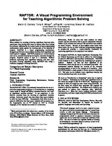
languages a program is represented by a directed graph [2, 3] and the he nodes of the graph serve as primitive instructions. Directed arcs between the nodes represent the data dependencies between the instructions [4].. In typical dataflow systems, instructions are scheduled for execution as soon as their operands become available lable i.e i.e.:: When data becomes available in the input arcs [5].This implies that each operator is limited to working on a single data item at a given time and the operation is applied immediately upon arrival of data data. This is a common drawback in most dataflow low systems since it becomes impossible to construct operators that are temporally aware (operators that depend on the history of data events that occurred prior to the current event). In the proposed system, each node has a queue associated with it on whi which ch the operation could be carried out, thus making it possible to have temporally aware operators in the dataflow (which is a key feature in CEP).. The governance of the queue is defined by a data window which could be defined as a length gth based, time based, data value based etc. The following diagram shows the typical view of our visual editor. Each component is designed to do a single task and the user can drag and drop the components as well as wire them up according to the requirement in much resemblance to dataflow editors such as Yahoo! Pipes [6] [ and ProGraph [7]. The following diagram shows the editor with a sample program constructed in it.
Figure. 1: Visual Editor
2.1 Execution We used Esper[8] as the backend complex event processing engine on top of which the constructed programs will be run. The events are represented as a Hash Map. The Map will contain the fields and the field values as key key-value pairs that describe a particular ar event. As for operations supported in the workflows, some operations are implemented as EPL statements, and in addition to those, some commonly used functionalities (String replace, tokenize etc.) are implemented as plain old java classes (POJO). This aallows llows for a wider range of operations to be supported in the workflows. All operators are limited to a ssingle ingle output (in order to simplify the conversion procedure) except for the multiplexer operator which takes in a single input and duplicates the input to 2. By combining an operator with the mux, users can get the output of an operator fed to multiple operators. The POJO based and EPL based operators are chained together in to a single workflow as explained plained in the following manner.
2.2 Chaining of operations The operators in the workflow are expressed as esper queries. (If the operator is not EPL based, a dummy statement is created). Chaining of the esper queries is done using the "insert into" clause in the Esper Query Language [8] [8]. The Non-EPL based components omponents are chained to the workflow
Computer Science & Information Technology ( CS & IT )
195
as listeners to the parent components’ EPL statement. The Non-EPL based operators receive the input events through this listener implementation. Then it carries out the operation on the events received and then pushes the results to the next component.
2.3 Conversion from UI to Runnable CEP program This is done as a 2 part process. First the UI representation is converted to an intermediate XML format. Then the XML format is converted to a Runnable CEP Program which is a collection of EPL queries and POJO objects chained together that are executed on top of an Esper engine. 2.3.1 Conversion from UI to XML The workbench converts the user created workflow in to an XML representation which details the components in the workflow as well as the connectivity among the components. The XML is of the following format: ... ...
The XML has 2 parts: and the section. The section describes the graph (the connectivity) of the workflow. It uses adjacency list format for describing the graph. The "id" attribute holds the id of the currently described component and the "forward-list" attribute contains a comma separated list of the components that are connected to the current component. (Only outgoing edges are described). The section describes each component in the workflow in its own xml item. Each implementing class for each component constructs the xml element for the respective component. This makes it possible to extend the workbench with new components without changing the core of the system.
2.3.2 Conversion from XML to Runnable CEP program The runtime web service forwards the received XML from the client to an XmlToGlutterDescConverter object. XmlToGlutterDescConverter takes the xml and creates a Glutter Descriptor object which will contain the necessary details for running the workflow. First the xml is parsed. Then in a loop over the components in the workflow, Event Types defined in the components are added to the Glutter Descriptor. Connectors and Non-EPL-based Operators define Event Types.
196
Computer Science & Information Technology ( CS & IT )
After that, the components are re-ordered according to the graph. It is necessary to register the esper statements in an order that ensures that all required statements are registered prior to registering a given statement. Specifically, this means that, if component C uses output of components A and B, then esper statements related to components A and B must be registered prior to registering statement of component C. Since the graph is a Directed Acyclic Graph, a topological sort on the component is used in constructing the ordered list of components. Once the ordered list is constructed, the following is done in a loop over the ordered list: If the current component is a non-EPL based component, then add a dummy statement "select * from ". If the forward component is a sink, add a listener to the dummy statement. Then create an object from the java class referred to by the class-id of the component description using reflection. Then, add the object as a listener to the parent component esper statement. If the current component is a multiplexer, then for all sinks in the forward list, create an instance of the sink and add it as a listener to the multiplexer input stream. Then create the esper statement for multiplex operation, which is of the following format: On insert into select * insert into select * output all Then add this statement as the statement corresponding to the component in the Glutter descriptor. Then modify all the esper statements corresponding to the components in order to chain the statements as per described by the graph. This is done by modifying the esper statements the following way: insert into The List of the ordered statements as well as the listener-to-statement relationships is stored in the GlutterDescriptor.
2.4 Running the workflow Once the GlutterDescriptor object is created, a GlutterRuntime object (which is a runnable object) is created by passing the GlutterDescriptor object to it. The GlutterRuntime object does the actual running on the workflow as described in the GlutterDescriptor. It first creates a separate Esper Engine. It then puts configuration entries for event types defined in the GlutterDescriptor. Then it registers the esper statements at the Esper Engine (The statements are ordered inside the descriptor according to the topological sorting). Then it registers the listeners to the statements as per the listener-to-statement relationship described in the GlutterDescriptor. Finally it constructs and initiates the connectors (the components which push events to the workflow).
3. COMMON CEP QUERY IMPLEMENTATIONS Select clause: By default, all esper statements for the components keep intact the field list that is received to that statement [8]. In most of the cases new fields are added or prevailing fields are modified. (This is true regardless of the implementation of the component being EPL based or non-EPL based).
Computer Science & Information Technology ( CS & IT )
197
However, the Subelement operator lets users select a subset of the fields received. (Thus implementing the EPL “select” construct). From clause: The “from” from” clause is constructed using the output stream of the parent operator of the current operator. However, severall components which support temporal qu querying erying capabilities require the “from” clause to contain a window to be applied on the receiving event stream. UI support for letting users specify the window to be applied is given on those components. Window definition definiti capability is separated out as a user input component in order to ensure reusability. This user input can be chained to the window specification text boxes in the window requiring components for specifying the window. This is illustrated in the followin following diagram:
Figure. 2: From Clause UI Construct
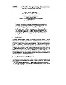
Where clause: The “Where” clause is implemented by the filter operator. The following criteria is supported: is greater than, is equal to, is less than, is not equal to, contains, not contains, in, not in, regexp, not regexp. The criteria can be logically connected using AND or OR logical operators.
Figure. 3: Where clause UI Construct
Conversion to Esper: select * from where The query string is created the following way: If the value "Any" is selected in the Any/All Combo box,, the filter criteria are combined using OR connector. If "All" is selected, the filter criteria are combined using AND connector. If the "Block" k" value is selected from the Allow/Block Combo box,, the whole filter expression is surrounded with a "NOT ( )" block (negating the filter expression). Else the filter expression is kept unaltered. Creation of EPL Statement fragment for each atomic filter criteria depend on the filter operation of that specific filter operation. Also, depending on whether the filter criteria contain a field value or a constant, the atomic filter criteria is changed.
198
Computer Science & Information Technology ( CS & IT )
Output clause: Output clause details the output rate st stabilizing abilizing of the statement. This is supported using the Valve operator. The user can specify an interval (based on length or time) and specify 4 modes of flow controlling: All, First, Last, Snapshot. Conversion to esper: output (all | first (length | seconds)
|
last
|
snapshot)
every
Order By clause: Order by clause which sorts the events is supported by the Sort operator. This operator will sort events collected in a data window according to user specified fields. User can specify a data window, and a sort expression. Conversion to Esper: select * from . order by [ asc | desc ] [, field2> [ asc | desc ] ]... Limit clause: Limit clause lets select the first N number of items from the receiving events in the specified window. This clause is supported by the Truncate operator. Users can specify a data window, and a limit value. (The limit value can be a variable defined using the Set Variable operator or a constant) Conversion to Esper: select * from . limit Join This operator lets users join 2 input streams in to a single event stream. The following followin join Types are supported: Left outer join, right outer join, full outer join, and inner join.
Figure. 4: Join UI Construct
Computer Science & Information Technology ( CS & IT )
199
Conversion to Esper: select * from . ( ( (left | right | full) outer) | inner) join . on [and ] ... Stream Duplication This is supported through the multiplexer operator. This duplicates the incoming stream and outputs 2 streams. (Both output streams will contain identical events and will be the same as the incoming stream). Conversion to Esper: The conversion is done as per detailed in the xml to running program conversion.
Aggregation The Aggregation component lets users calculate aggregated values based on events collected in a data window. (See data window section for details on data windows). This component adds temporal querying capabilities in workflows. The following aggregation value calculations are supported: avedev, avg, count, max, median, min, stddev, and sum. User can specify whether all values or only the distinct values of the set is considered by checking / un-checking the checkbox "All". Conversion to Esper: select *, ([all|distinct] ),[([all|distinct] )]... from . Window Definition One of the key aspects of CEP is the ability to perform temporal queries [1]. In order to perform such temporal queries, it is required to specify a window on which the operation is applied. Since this is a common requirement required by many operators, a separate define window user input component is built in the workbench which can be used to specify windows. The following window types are supported: Length, Length_batch, Time, Externally timed. Time_batch, Timelength, Time_accumilation. Keep all, sorted, unique, groupby, Last event, First event, First unique, First time, First length [8]. Cascading of multiple windows to specify compound window definitions are also supported in the visual editor through chained “define window” components as shown below:
200
Computer Science & Information Technology ( CS & IT )
Figure. 5: Window Definition
Variable Set Variables in Esper can be used in output clauses, filter criteria etc. The Set Variable operator lets users specify a variable and its assignment expression. This variable can be later on used in other components as required. The variable def definition inition is not chained to the other statements. The variable definition is passed as a separate attribute and is added to the Esper engine without chaining to the other statements. In order to continue the workflow, a dummy esper statement (select * from …)) is added to the chain.
4. IMPLEMENTATION OF PR PROGRAMMING CONSTRUCTS 4.1 Variable Assignment (Field value) This supports the following variable types as field values in the events. Long, Double, String, Array[Long], Array[Double], and Array[String]. It is possible to create new fields as well as assign prevailing fields’ new values in all of the above supported data types. This is done through mainly the use of 4 operators: Field Update, Array Update, Cast, and Array Iterator. Field Update: This operator lets users create a new field as well as modify the content in a prevailing field. The created field / modified field will be of string type. Field Update makes it possible to do field assignment for the String type. The cast operation lets users cast a prevailing field of a different data type to a different (compatible data type). Through the combination of Field update followed by the Cast operator, users can assign values to all primitive data types (String, Long, Double). Array Update: This is the Array counterpart of the Field update operator. This operator allows users to create new fields / assign new values to prevailing fields of Array[String] type. The user can specify the field name and the expression for the field. The expression required is a comma separated list of items. An item in the list can be a constant value or a currently present field value of type array. If specifying a currently available field, user can optionally specify the range of the array to take.
Computer Science & Information Technology ( CS & IT )
201
Array Update lets assign Array[String] type field values. This followed by the Array Iterator operator (given a Cast operator as the array iteration operator) lets users create fields of other array types. Thus, the user can assign values to any of the supported variable types in the above manner.
4.2 If Conditional The “If conditional” can be implemented using the filter component. The filter component only forwards an event to the next component if the filter criteria are met, thus acting as a typical “If” conditional. 2nd implementation: (External –If) There is a different implementation of If conditional that can be useful when the conditional is not based on the field values in the event stream. (The conditional is based on an external stream of events / external trigger). The following diagram shows the implementation:
Mux Filter 1
Filter 2
Field update1
field update2
(dummy2=”on”) (dummy2=”off”) Field Update (dummy1=”on”)
Union
Join
The above construct lets users control an event stream according to a conditional in a different stream.
4.3 If-Else Construct The If-Else Construct can be achieved in the following manner: Mux Filter 1
Filter 2
202
Computer Science & Information Technology ( CS & IT )
The filter 2 conditional must to be specified as the exact opposite of the filter1 conditional.
4.4 Loop At the event level, looping is done across the workflow, thus no special component is required for looping over events. (All operations are applied to events coming in that order). However, for looping across an event field of type Array, the users can use the Array Iterator operator. The Array Iterator operator is a higher order component, thus the user can specify which operation to apply for each item in the array.
5. LIMITATIONS Currently, the system only supports events represented as a Map. In addition to that, the field types are limited to the following types: String, Long, Double, Array[String], Array[Long], Array[Double]. Currently events do not support compound event fields (an event cannot contain an event inside it). For pattern recognition we currently use the match recognize syntax (instead of the pattern guard mechanism), thus limiting the pattern recognition capabilities.
6. CONCLUSION CEP application development requires considerable effort from the programmer, and requires thorough understanding of the query language [1]. In addition to that, coding in query level makes it harder to visualize the program and the execution paths of it, thus making it difficult to understand the program and modify it. Therefore, a visual programming environment for Complex Event Processing is a vital step in making CEP application development much easier, faster and intuitive.
REFERENCES [1] [2] [3] [4] [5] [6] [7] [8]
[9]
“How to make the web work in real-time” [Online] Available: http://complexevents.com/ [Accessed: November 24, 2009] Arvind And D.E. Culler. Dataflow architectures. Ann. Rev. Comput. Sci. 1, 225–253, 1986 A. Davis, and R.M. Keller. Data flow program graphs. IEEE Comput. 15, 2, 26–41, 1982 P.R. Kosinski. A data flow language for operating systems programming. In ‘Proceedings of ACM SIGPLAN-SIGOPS Interface Meeting.’, SIGPLAN Not. 8, 9, 89–94. 1973. W.M. Johnston, J.R. Paul Hanna, and R.J. Millar. Advanced in Dataflow Programming Languages . In ‘ACM Computing Surveys, Vol. 36, No. 1, March 2004, 2004. http://pipes.yahoo.com/pipes/docs [Accessed: December 21, 2009] EsperTech. (2009). Esper Reference Documentation [Online] Available: http://esper.codehaus.org/esper-3.5.0/doc/reference/en/html/index.html [Accessed: October 20, 2009] E. Baroth, C. Hartsough, "Visual Programming in the Real World", in Visual Object-Oriented Programming, Concepts and Environments (ed. M. Burnett, A. Goldberg, T. Lewis), Manning 1995, pp.21-42 “Event stream intelligence with Esper and NEsper” [Online] Available: http://esper.codehaus.org/ [Accessed: October 07, 2009]