developers manage software development complexity using models at ... piece of code that can be called by a thread or another .... This state-transition diagram.
Verification Based Development Process for Embedded Systems T. Correa§ , L.B. Becker§ , J.-P. Bodeveix∗‡ , J.-M Farines§ , M. Filali∗‡ ,
F. Vernadat†‡ ∗
CNRS ; IRIT ; Universite´ de Toulouse, 118 route de Narbonne, F-31062 Toulouse, France †
‡
CNRS ; LAAS ; 7 avenue colonel Roche, F-31077 Toulouse, France
Universite´ de Toulouse ; UPS, INSA, INP, ISAE, UT1, UTM ; F-31062 Toulouse, France §
Federal University of Santa Catarina, Florianopolis, Brazil
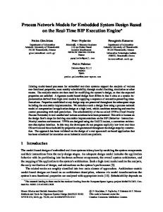
Abstract: Designing safety critical systems is a complex task due to the need of guaranteeing that the resulting model can cope with all the functional and non-functional requirements of the system. Obtaining such guarantees is only possible with the use of model verification techniques. This paper presents an approach aimed to fulfill the needs of critical system design. The proposed approach is based on the Architecture Analysis and Design Language (AADL), which is suitable to describe the system’s architecture. It contains a sequence of model transformations that easies the verification of the designed AADL model and so assures its correctness. It must be highlighted that this is not performed in a single step, as it is possible to verify AADL models with different abstraction levels, which allows successive refinements in a top-down approach. We use a case study from an Autonomous Parking System to illustrate the proposed development process. Keywords: safety-critical systems, design approach, model-verification
1. Introduction Modern safety-critical systems are getting more and more complex and, at the same time, have become indispensable nowadays. Almost every system that in the past was simply mechanic (e.g. cars, trains, airplanes) is now equipped with an embedded computing systems. Also, most of the times, such systems are safety-critical.
In order to handle such increasing complexity it is necessary to use proper Software Engineering methodologies or development process. By appropriated we understand that techniques should both easy the modeling discipline and provide model-verification facilities. Model-verification is crucial for safety-critical systems design because it allows guaranteeing that the designed model respect the application requirements and constraints. In this context, the Architecture Analysis & Design Language (AADL) [7] seems to be a suitable choice. AADL is a modeling language that allows early analysis of a system’s architecture. It supports the modeling of both software and hardware components in a hierarchical manner using a set of components connected through ports. AADL defines properties that can be attached to modeling elements in order to give an abstract specification of the dynamic architecture of the system. Real-time constraints are attached to threads, ports, buses, and processors (e.g. dispatch protocol, period, deadline, processing power, hardware-software mapping, etc). The AADL language can also be extended by defining new properties or by attaching specific languages to some elements. Although AADL precise semantics makes it suitable for model verification, how to perform such a task is still an open question. For this reason, we present in this paper a solution that overcomes this problem. Our approach consists in supporting model verification taking into account irregular behaviors and data. Another important feature from our proposal is
that it follows the Model Driven Engineering (MDE) principles, as design is intended to remain in highlevel abstraction levels and does not need to worry about the low-level details from the performed model transformations. We can say that the proposed process supports the safe design of the system’s architecture, once the resulting system architecture goes through several verification steps in order to assure its correctness. To reach this goal it is performed a sequence of model transformations, maintaining the principles of MDE. It starts with an AADL model and finishes with an automaton model that can be verified. The rest of the paper is structured as follows: Section 2 discuss some related works. Section 3 gives a brief introduction to the AADL language. Section 4 presents the proposed development process and our autonomous parking case study. Section 5 presents the techniques and toolset used to verify temporal properties of AADL models. Finally, section 6 draws the conclusions of this work.
2. Related Work 2.1. Design Languages UML [4] was created to be a general purpose modeling language for software development. However, its wide acceptance has suggested its use also to design distributed embedded real-time systems. UML extensions where proposed since it lacks suitable constructions/abstractions to represent specific concepts from embedded and real-time systems domains. The first attempt to overcome such deficiencies was the UML profile for Schedulability, Performance, and Time (SPT) [11]. The SPT profile provides concepts to allow both model-based schedulability and performance analysis, and also a rich framework to model time and time-related mechanisms. However, experiences in applying SPT revealed shortcomings within the profile in terms of its expressiveness for modeling UML real-time and embedded phenomena. The amount of issues in the SPT profile resulted in a Request for Proposals (RFP) for a new UML profile for specifying embedded and real-time systems. Consequently, a new profile named Modeling and Analysis of Real-Time and Embedded systems (MARTE) [12] was proposed. It was accepted by OMG in July 2007. The MARTE profile addresses: (i) new elements to be added to UML 2.x; (ii) design of both software and hardware aspects of embedded system; (iii) broader schedulability and performance analysis capabilities; (iv) specification of embedded systems
characteristics, such as memory capacity and energy consumption; (v) support to component-based architectures; (vi) other computational paradigms, such as asynchronous, synchronous, and timed; and (vii) compliance with the UML profile for Quality of Service and Fault Tolerance. In summary, MARTE is intended to cope with two concerns: modeling of real-time and embedded systems features, and to support analysis of system properties. MARTE Design Model package provides first-order language constructs to specify model expressing specific phenomena of real-time and embedded systems. It allows platform modeling in terms of software or hardware platforms. MARTE sees platforms as a set of resources, possibly comprising finergrained resources into a hierarchical manner, in which each resource offers at least one service. A resource is seen as a service provider with finite capacity, which usually comes from physical limitations of the underlying hardware (e.g. memory capacity, bandwidth, processing power, etc.). Considering software platforms, it provides a model-based view for concepts provided by RTOS API, such as semaphores and concurrent tasks (or processes). On the other hand, regarding hardware platforms, concepts to assist software design and allocation are provided using a highlevel hardware description model instead of block diagrams. Additionally it helps in the analysis of realtime and embedded properties, and also in hardware models simulation, which depends on the description detail level and simulation accuracy.
2.2. Methodologies for Embedded Systems Design Designing new generations of embedded real-time systems is so complex that new design methodologies where proposed. The Model Driven Engineering (MDE) [13], for instance, is an initiative to help developers manage software development complexity using models at higher levels of abstraction. It can be understood as a philosophy that guides systems development. The key aspect in this technology is allowing the design of models that are decoupled from their target platform. One example of this technology is the OMG initiative called MDA [10]. MDA does not define explicitly the diagrams that should be used and neither the required transformations among the three different kinds of models that it defines: Computational Independent Model (CIM), Platform Independent Model (PIM), and Platform Specific Model (PSM). All these models, or visions, may be used as system’s development tiers, where each tier can
be transformed into another representative model that can be used to generate specific code to some architecture. The model, in general, represents elements using the UML, therefore they can be represented using the Meta Object Facilities (MOF).
2.3. Tool Support Among the main benefits of the emerging model driven approach, one can cite its enhanced possibilities for early verification. Actually, many recent tools have been proposed to support different kinds of verification. With respect to our concerns, timing verification tools have been an active area of research over these last years. It is interesting to remark that although most of these tools are based on existing theoretical models, e.g., timed automata, Petri nets, the limitations (especially with respect to combinatorial explosion and scalability) of which are well known, the effort has been undertaken to achieve them. In fact, it is hoped that first, the abstraction and the structure brought by the modeling driven approach and second, the adoption of a specific execution model will help to struggle against these limitations. Along these lines, we can cite the Cheddar [5] scheduling tool which proposes dedicated analysis for the AADL execution model. Currently, it considers mainly analytical models. Future versions should take into account more detailed behavior descriptions [8]. The tools Uppaal Port [9] and Pola[2] are based on the traditional model checking approach. Uppaal Port is based on timed automata and supports component based development. In order to reduce the combinatorial explosion Uppaal Port adopts a synchronous like execution model which restricts interleavings of the asynchronous approach. Moreover, it proposes partial order techniques for reducing space space explorations. The tool Pola is based on timed Petri nets. It proposes specific support for the AADL execution model.
3. A brief overview of AADL AADL is an architecture design language standardized by the SAE. This language has been created to be used in the development of real time and embedded systems. As a successor of MetaH, AADL capitalizes more than 10 years of experiments. MetaH is a language developed by Honeywell Labs and used in numerous experiments in avionics, flight control, and robotic applications. AADL also benefits from the knowledge on ADLs acquired at CMU during the development of several ADLs, like ACME and Wright.
AADL contains all the standard concepts of any ADL: components, connectors used to describe the interface of components, and connections used to link components. The set of AADL’s components can be divided in three partitions: the software components (process, thread, thread group, subprogram, and data), the hardware components (processor, bus, memory, device), and a System component. Components can communicate through ports, synchronous calls, and shared data. A process represents a virtual address space, or a partition, this address space includes the program defined by its sub-components. A process must contain at least one thread or thread group. A thread group is a logical organization of threads in a process. A thread represents a sequential flow of execution, it is the single AADL component that can be scheduled. A subprogram represents a piece of code that can be called by a thread or another program. A data models a static variable used in the code, they can be shared by threads or processes. A processor is an abstraction of the hardware and the software in charge of the scheduling and the execution of threads. The memory represents any platform component that stores data or binary code. The buses are communication channels used to connect different hardware components. The devices represent interfaces between the system described and its environment. Systems allow composing software components with hardware components. The interactions can be defined at a logical and a physical level. At a physical level, software components are associated to hardware components, a thread to a processor, or a data to a memory for example. The logical level is used to describe the communication between hardware and software. At a logical level we can define communication connections between processors or devices and software components. AADL uses the notion of mode to determine a set of active components. This mechanism allows describing dynamic architectures through a static set of components. We consider here the behavior annex [8] attached to threads or devices, which is used to specify an abstract behavior for these components, allowing to make data dependent analysis.
4. The Proposed Development Process This section presents our proposed development process for critical embedded systems. It is possible to say that this process supports the safe design of the system’s architecture using MDE’s principles. By safe design we mean that the resulting system
architecture goes through several verification steps in order to assure its correctness. To reach this goal it is performed a sequence of model transformations, which starts with an AADL model and finishes with an automaton model that can be verified. This section skips the details of the verification chain (which is covered in the next section) and concentrates in the high-level steps of the proposed process, which are shown in Figure 1. 1. Requirements Definition 2. Functional Modeling + Simulation Proposed AADL process
3. Environment Description
4A. Sw Architecture Modeling
4B. Hw Architecture Modeling
5. Sw/Hw Mapping 5B. Architecture Simulation 6. Refine Real‐Time Properties
a verification step fails the designer should either backtrack to higher abstraction levels of the AADL model and its properties or change assumptions made in earlier levels. For example, if there is an error in the timing verification (step-7), then the designer should be able to judge if the problem is due to the result of step-4A (proposed software architecture) or to the result of step-4B (target hardware architecture). The reminder parts of the current section details the steps depicted in Figure 1. We use an Autonomous Parking (AP) System case study to elucidate the work performed in each step. Moreover, we concentrate the discussions on the software architecture modeling (step-4A). The target hardware architecture definition (step-4B), although very important in the context of the proposed process, should be subject of additional investigation and therefore is left out of this work.
4.1. Requirements Definition
7. Timing Verification
Fig. 1. Proposed Design Flow We understand that, as in any system development, the initial step is the definition of the functional and non-functional requirements of the system, resulting in a set of requirements. Then it is followed by the design of a functional model for the system (e.g. Lustre or Simulink model). The proposed process itself starts in step-3 with the design of the AADL model, providing the specification of the external devices (environment) that interact with the system. step-4 is split in two parts: (4A) software architecture modeling/verification and (4B) hardware architecture modeling. The overall result here should be an AADL model with basic properties already verified and a hardware architecture potentially capable to run the designed software model. In step-5 a mapping from the modeled software components to the hardware model is performed. The result is a complete AADL model. In step-6 it is suggested that the real-time properties of the AADL model should be updated with the precise timing information coming from the simulation of the software in the target platform, which is conducted in step-5B. The proposed development process is concluded in step-7 with the final model verification, which uses as input the AADL model updated with the precise timing information. After that, it should be possible to make automatic codegeneration of the application. It is important to highlight that the design flow among the steps is not unidirectional. Every time that
The initial step in any development methodology is to define the requirements of the system to be developed. This includes both functional requirements (FR) and non-functional requirements (NFR). While the former depicts the main functionalities to be performed by the system, the latter imposes restrictions to those functionalities. Table 4.1 presents the list of requirements from the AP system, which has three main functionalities: (FR1) start/stop the system using a GUI; (FR2) search for a parking slot; and (FR3) park the car. NFRs are like properties that must be satisfied by the related FR. For example, NFR2.2 states that if the speed is too high (over 20km/h), than it is not possible to search for a parking slot.
4.2. Functional Modeling and Simulation In many applications, especially those related with control systems, it is required to first design a functional model of the system and to simulate it before any design decision on the system architecture is carried on. This is used either to provide a deeper understanding of the system functionalities or to test/simulate control solutions in early development stage. Tools like Scade/Lustre and Matlab/Simulink are often used for this propose.
4.3. Environment Description The third step of the proposed process consists of using AADL to describe the environment that interacts
FR1 - Start/stop the system using a GUI Description: The system must be explicitly activated by the driver to start operation NFR1.1 To start the system the speed must Maximum speed be kept at ≤ 20Km/h NFR1.2 The system must inform the user On operation while it is working NFR1.3 The system must inform the user Finished as it is turned off FR2 - Search for a parking slot (real-time operation) Description: When activated, the system must start searching a new park slot as the vehicle moves forward NFR2.1 The system must inform the user Driver alert when a new parking slot is found NFR2.2 If the speed is too high (over 20km/h) Safety than it is not possible to search a parking slot FR3 - Parking (real-time operation) Description: The driver must trigger the beginning of the parking after a parking slot is found. The system controls the speed and direction of the vehicle. NFR3.1 The system is allowed to start parking Safety only if the current speed is zero NFR3.2 The system must be halted immediately Emergency Stop if the driver moves the wheel NFR3.3 The system must alert the driver when Finish allert the parking maneuver is finished
Fig. 2. AP System Environment Description.
TABLE I. Requirements set of the Autonomous Parking (AP) System
with the system under development. In other words, it is necessary to define the set of interactions of the system with the external devices, such as sensors, actuators, user interface, etc. For this reason it is suggested here the use of a high-level AADL diagram. Figure 2 presents the diagram designed for the AP system, where it is possible to observe the main system in the center (named ParkingCtrl) surrounded by the devices. An advantage of using AADL for such purpose is that it allows detailing each message exchanged between the system and the devices, including information like data type, arrival pattern, and time constraints. In this phase it is assumed that two different kinds of external devices can exist: reused devices and new devices. While devices like sensors and actuators are normally reused from previous applications, devices like User Interfaces (UI) are normally designed on demand for each application. New devices can be subject of formal verification prior to its use in the model. Therefore it is necessary to specify the device’s behavior. In the scope of this work it is suggested to describe behavior using finite automatons. To exemplify the verification of devices behavior in the AP system we selected the UI device (UIController). A possible behavior of this device
Fig. 3. User interface behavior is depicted in Figure 3. This state-transition diagram states that, independently of the status of the application, the driver can always turn off the system (NFR1.3). This can be proof by the existence of the user event Off! in every possible execution state of the system. Although very simple, this is an example to show that it is possible to use verification already at this level.
4.4. Software Architecture Modeling The software architecture modeling (step-4A) is probably the most important phase of the proposed design process. This phase may have several steps of iterations, as depicted in 4. This is due to the fact that the designer may create several AADL models, from more abstract to more detailed ones, and that all these models should have its properties verified. In the first iteration the designer must detail the AADL system process (e.g. ParkingCtrl at Figure 2) into a set of subcomponents (that can be either processes or threads). As this detailing is completed, model verification is performed, as explained in the next section. If the verification fails (many times due to the lack of information in the model), a new refinement
in each component should take action, starting new iterations. Following this approach, each component of the AADL model can derive into several subcomponents. By definition, the successive refinements will only finish as the model contains enough details to be proof correct or incorrect by the model verification. Each detailed model (i.e. iteration) should, however, cope with the abstract behavior defined for the higher level component. 3A. Software Architecture Modeling
seen as a kind of temporal decomposition from the set of available functions. Therefore it is necessary to identify how many different operation modes the system should have. These modes can be used to guide the modeling of the distinct AADL processes that will be used to decompose the system in subparts. In our case study, the sub-functions of the first decomposition are more or less analogous to the operation modes. Figure 6 shows the automaton in charge of representing the AP system behavior.
Idle
A1. Select System or Thread
Slot
turnOn! turnOff! abort!
parkingInProgress!
finished!
A2.2. Architecture Refinement
Manouver Properties
turnOff! abort!
A3. Verification no success?
Fig. 6. Basic operation modes of the AP System.
yes no
more verification
Fig. 4. Interative-nature from ADPB Architecture Refinement: The architecture refinement process consists of successive model refinements and verification, as suggested in the design flow from Figure 5. It starts with identifying the operation modes (1) and threads (2) of the system, being followed by the mapping of functions to threads (3). Afterwards the designer can make the connections among the threads (4) and associate an execution mode to each thread (5). A2.2. Architecture Refinement 1. Identify modes yes 2. Identify threads new refinement? 3. Map functions to threads A1. Select System or Thread 4. Add connections
5. Assign modes to threads
Fig. 5. Refined steps from Architecture Refinement We suggest organizing the functionalities of the system using different operation modes. This can be
After the identifications of the system (sub)functions it is possible to decompose the AADL model into different threads. This can be either the first level of decomposition of the AADL-system or a refinement of an existing thread. Defining connections means to establish the information exchange among the system subparts (threads). This also requires the definition of the data types associates with each port that transfer data. For the AP system case study, the first level of decomposition consists basically in three threads, as shown in Figure 7. SystemManagement is used to start or halt the AP system by means of the graphical interface (FR1), SlotSelection is responsible to search for a parking slot (FR2), and finally ParkingManeuver is responsible to perform the parking (FR3). Once we have defined both functions and threads it is necessary to relate them, i.e. define which functions belong to which thread. Here, information like periodicity and deadlines of threads and functions can be defined. The result of this mapping in the AP system is shown in Figure 7. As it can be observed, in this level every thread is responsible for one FR of the system. Finally it is required to define in which operation modes each thread will be active. This represents a common modeling procedure to make the timing decomposition of the system functionalities. In AADL this is performed directly in the code, i.e. there is no graphical representation for this association. It must be highlighted, however, that it is possible to associate
architecture using MDE’s principles. By safe design we mean that the resulting system architecture goes through several verification steps in order to assure its correctness. To reach this goal it is performed a sequence of model transformations, which starts with an AADL-like model and finishes with an equivalent automaton model that is suitable for verification. The verification process we have been working on uses AADL models as input and performs the model checking of LTL properties. Moreover, schedulability and buffer overflow can also be analyzed, as well as user defined properties. This process is split in the following phases (Figure 8): Fig. 7. AADL model of parking control system (in the first decomposition)
AADL model
LTL property
AADL2FIACRE
a thread with several operation modes. Model Verification: It is a modeler decision whether he wants to perform further refinements or to verify the behavior of the current model. In order to make the model verification it is necessary to provide the abstract behavior of each thread that belongs to the AADL model. Afterwards designer should define the set of properties of interest to be verified and perform the verification process. Such process is detailed in the section 5.
4.5. Time-Related Levels To verify the real-time properties of the model it is necessary to make the Software/Hardware Mapping (step-5). After this step, every thread must be associated with a specific processor. The hardware architecture must have at least one processor. Thereby, in the Real-Time Properties Refinement (step-6), the designer can add additional timing information in the AADL model to be further verified. Such information must be obtained using, for example, model simulation on top of the target architecture. Thereby it is possible to obtain the worst case execution time (WCET) for each function of the system prior to its implementation. The last step of the proposed process is in charge of making the verification of the timing properties. Schedulability and response-time analysis are exemples of possible properties to be verified.
5. Verification Process It is possible to argue that our proposed verification process supports the safe design of the system’s
Fiacre model
frac
TTS model
selt
diagnostic
tina Automaton model
Fig. 8. The verification process. •
• • • •
Use of the OSATE-TOPCASED [14], [15] environment for AADL model edition and XMI generation. We consider AADL together with its behavioral annex. Translation of AADL XMI models to Fiacre [1]. Translation of Fiacre to the timed transition system (TTS) input format of Tina toolbox. Translation to an untimed automaton via an LTLpreserving time abstraction. Verification of LTL properties using the Selt tool from the Tina toolbox.
5.1. Verification Tools TINA is a software environment to edit and analyze Petri nets, Time Petri nets, Time Transition Systems, and also extension of these nets handling data, priorities and temporal preemption. Beside the usual editing and analysis facilities of similar environments, the essential components of the toolbox are a state space abstraction tool (also called Tina) and a model checking tool (selt). Detailed information about the toolbox capabilities can be found in [3]. TINA offers various abstract state space constructions that preserve specific classes of properties of the state spaces of nets, like absence of deadlocks, linear time temporal properties, or bisimilarity. For untimed systems, abstract state spaces help to prevent
combinatorial explosion. For timed systems, TINA provides various abstractions based on state classes, preserving reachability properties, linear properties or branching properties. State space abstractions are provided in various formats suitable for existing model checkers. The TINA toolbox also provides a native model checker, selt. Selt allows one to check more specific properties than the general ones (boundedness, deadlocks, liveness) already checked by the state space generation tool. Selt implements an extension of linear time temporal logic known as State/Event LTL [6], a logic supporting both state and transition properties. The modeling framework consists of Kripke transition systems (labeled Kripke structures, the state class graph in our case), which are directed graphs in which states are labeled with atomic propositions and transitions are labeled with actions. State/Event-LTL formulas are interpreted over the computation paths of the model. They may express a wide range of state and/or transition properties. Some typical formulas are the following (a formula evaluates to true if it does so on all computation paths, X, F, G and U are LTL modalities, p, q are formulas): p p holds at the start X p p holds at the next step (next) G p p holds all along the path (globally) F p p holds in a future step (eventually) p U q p holds until q holds (until) and q holds eventually. We also use the weak until operator W. p W q holds until q holds. It is not mandatory that q eventually happens. Real-time properties, like those expressed in so called “timed temporal logics”, are checked using the standard technique of observers, encoding such properties into reachability properties. The technique is applicable to a large class of real-time properties and can be used to analyze most of the “timeliness” requirements found in practice.
5.2. Properties Verification Currently, we support the verification of three kinds of properties: (i) implicit properties taken into account by the translator and leading to deadlock when not satisfied; (ii) user properties specified through AADL real-time observers; and (iii) properties specified directly in linear temporal logic. Implicit properties: For the moment, two implicit properties are taken into account by the translator: • Schedulability: threads are scheduled using a fixed priority protocol with user-specified preemption points. Deadline events are generated by the
translator. If a deadline occurs while a thread is still active, a specific deadlock is generated. • Buffer overflows: AADL defines the property Overflow Handling Protocol which specifies what to do in case of overflow. Either the oldest or the newest data is lost, or the component is erroneous. The latest case is handled by the translator to generate a specific deadlock if the capacity of the input buffer is exceeded. Real-time observers: Some properties such as bounded response time can be expressed using AADL threads acting as real-time observers. The component to be checked is linked to an observer which plays the role of its environment and checks its responses. For example, properties of the maneuver component of the parking can be verified by specifying an environment as the following. It checks that the highSpeed signal is emitted one period (fixed here at 10ms) after the speed becomes non zero. Otherwise, the err state would be reached. It also checks that the abort signal is sent if the wheels are moved. The selt model checker is used to show that the err state is unreachable. thread implementation EnvironmentThread . imp annex b e h a v i o r s p e c i f i c a t i o n {∗∗ states s0 : i n i t i a l complete s t a t e ; s1 , s2 , e r r : complete s t a t e ; transitions s0 −[]→ s0 { speed ! ( 0 ) ; r a n g l e ! ( 0 ) ; } ; s0 −[f i n i s h e d ?]→ s0 ; s0 −[]→ s1 { speed ! ( 1 0 ) ; } ; s0 −]→ [ s2 { wheelMoved ! ; } ; s1 −[highSpeed?]→ s0 ; −− d e t e c t e d i n l e s s than t h e p e r i o d s1 −[on highSpeed ’ count = 0]→ e r r ; s2 −[a b o r t ?]→ s0 ; s2 −[on a b o r t ’ count=0]→ e r r ; ∗∗}; end EnvironmentThread . imp ;
Remark Response time information could be added to the AADL model as properties of flow specifications and thus be implicitly checked. However, this is not easy if response time is greater than the minimum period of the input signal. Here, our observer supposes that speed does not change while waiting for the highSpeed signal. properties Linear time Temporal Logic: Temporal can be checked on the closed system. They can be expressed in linear temporal logic (LTL) and passed to the selt tool. Atomic properties are either event properties or state properties. For example: • If the speed is too high, the interface cannot get the found message while the search has not
6. Conclusions
been restarted. � (highSpeed ⇒ (¬found W startSearch))
In this paper we presented a verification approach and the related toolset to design safety critical sysThis property is in fact not satisfied because tems using the AADL language. This work is part of a taking into account the speed information and more general project, which also covers the hardware aborting the process needs one cycle. We use architecture definition in more details, going towards the hyperperiod event H to reformulate the propproducing safe models for critical applications. It must erty as follows: if the speed is too high, starting be highlighted that in the end of the process it is from the next hyperperiod signal, we cannot get possible to make automatic code generation from the the found message unless startSearch has AADL model for a given platform. been pushed. It should be noticed, however, that given the complexity of the situation, the guarantee of the existence �highSpeed ⇒ (¬H U H∧(¬found W startSearch)) of a correct solution cannot be asserted. This also applies to the implementation derived from the gener• It is possible to park the car, i.e. there exists an ated model. To overcome this problem, designer feedexecution path leading to a state where the car backs are necessary and, more generally, it should is parked. It is expressed as a negated property: be wise to superpose to the software engineering it is not true that in any execution, finished is process risk management. never sent. Currently there is no automated process to transforms the requirements identified at a high level of Parking 6|= �¬finished abstraction and the final concrete properties to verify on the final formal model. This is currently under • The car can be parked infinitely often. It is also investigation in our group. expressed as a negated property: Finally, this study has made us aware of the fact that linear temporal logic although simple is not rich Parking 6|= ♦�¬finished enough for expressing some required intuitive properties. In this paper, we have suggested the use of muModal mu-calculus: There exists some useful propcalculus. We intend to study in future work suitable erties that cannot be expressed neither in LTL, nor patterns to enhance the use of such a logic. Another in CTL. For example, the fact that the user interface further direction of this research would be providing a can be reinitializable by the user whatever the system risk analysis to assist the design. does. To solve this problem, it can be expressed in modal mu-calculus using the macro bellow, where U is the set of user events and ϕ the property to be Acknowlegements reachable, i.e. the initial state. It defines the set of states from where ϕ is reachable by user events even This work was developed with the grant CAPES if non user events are fired as a smallest fixed point STIC-AmSud 003/07 TAPIOCA : Timing Analysis and (the min operator). Program Implementation On Complex Architectures _ and supported by the French AESE project Topreachable(U, ϕ) = min X | ϕ∨([−U]X∧ ([e]X∧heiX) cased. e∈U
Such a property can be verified on atemporal models by the muse tool of the Tina toolbox. It must be associated with a stability property expressing that non-user events do not leave the initial state. It would also be possible to encode a possibly realtime winning strategy using the AADL behavior annex and check that the initial state is reachable using an LTL property over the generated abstract automaton. In our example, this is very simple because a user command can always be used.
References [1] B. Berthomieu, J.-P. Bodeveix, P. Farail, M. Filali, H. Garavel, P. Gaufillet, F. Lang, and F. Vernadat. Fiacre: an intermediate language for model verification in the TOPCASED environment. Proceedings of the 4th European Congress on Embedded Real-Time Software ERTS’08(Toulouse, France), January 2008.
[2] B. Berthomieu, F. Peres, and F. Vernadat. Model checking bounded prioritized time petri nets. In K. S. Namjoshi, T. Yoneda, T. Higashino, and [15] Y. Okamura, editors, ATVA, volume 4762 of Lecture Notes in Computer Science, pages 523– 532. Springer, 2007. [3] B. Berthomieu, P. Ribet, and F. Vernadat. The tool TINA – construction of abstract state spaces for petri nets and time petri nets. International Journal of Production Research, 42(14), 2004. [4] G. Booch, J. Rumbaugh, and I. Jacobson. The Unified Modeling Language: User Guide. Addison-Wesley- Longman, 1999. [5] P. Dissaux and F. Singhoff. Stood and cheddar: Aadl as a pivot language for analysing performances of real time architectures. In 4th European Congress ERTS EMBEDDED REAL TIME SOFTWARE, Jan. 2008. [6] S. C. Edmund, E. M. Clarke, N. Sharygina, and N. Sinha. State/event-based software model checking. In In Integrated Formal Methods, pages 128–147. Springer-Verlag, 2004. [7] P. Feiler, D. Gluch, and J. Hudak. The architecture analysis & design language (AADL): An introduction. Technical report, Software Engineering Institute, Carnegie Mellon University, 2006. [8] R. B. Franca, J.-P. Bodeveix, M. Filali, J.-F. Rolland, D. Chemouil, and D. Thomas. The AADL behaviour annex – experiments and roadmap. In ICECCS ’07: Proceedings of the 12th IEEE International Conference on Engineering Complex Computer Systems, pages 377–382, Washington, DC, USA, 2007. IEEE Computer Society. ˚ [9] J. Hakansson, J. Carlson, A. Monot, P. Pettersson, and D. Slutej. Component-based design and analysis of embedded systems with uppaal port. In ATVA ’08: Proceedings of the 6th International Symposium on Automated Technology for Verification and Analysis, pages 252–257, Berlin, Heidelberg, 2008. Springer-Verlag. [10] OMG. MDA specifications. Technical report. http://www.omg.org/mda/specs.htm. [11] OMG. Uml profile for schedulability, performance, and time specification. Technical report, 2003. [12] OMG. UML profile for marte. Technical report, 2008. http://www.omgmarte.org/Documents/Specifications/0806-09.pdf. [13] D. Schmidt. Model-driven engineering. IEEE Computer, 39(2), 2006. [14] S. A. Team. OSATE: An extensible source aadl tool environment. Technical report, Software En-
gineering Institute, Carnegie Mellon University, 2004. Topcased. (toolkit in open-source for critical apllications and systems development). http: //www.topcased.org.