Very Large Scale Integration (VLSI) Lecture 10
Dr. Ahmed H. Madian
[email protected]
Dr. Ahmed H. Madian-VLSI
1
Content
Manufacturing Defects
Wafer defects Chip defects Board defects system defects
Testing
Testability Fault models Stuck-At-faults Soft errors Test Pattern Generation Design for testability
Dr. Ahmed H. Madian-VLSI
2
Manufacturing Defects
Wafer Defects from misalignment, dust and other particles, “stacking” faults, pinholes in dielectrics, mask scratches & dirt, thickness variations, layer-to-layer shorts, discontinuous wires (“opens”), circuit sensitivities (VTH, LCHANNEL). Dr. Ahmed H. Madian-VLSI
3
Manufacturing Defects (cont.)
Chip Defects from scratching in handling, damage during bonding to lead frame, manufacturing defects undetected during wafer probe (particularly speed-related problems).
Dr. Ahmed H. Madian-VLSI
4
Manufacturing Defects (cont.)
Board Defects from damage during board insertion (thermal, ESD), infant mortality (manufacturing defects that show up after a few hours of use). Also noise problems, susceptibility to latch-up...
Dr. Ahmed H. Madian-VLSI
5
Manufacturing Defects (cont.)
System Defects that only appear after months or years of use (metal migration, oxide damage during manufacture, impurities).
Dr. Ahmed H. Madian-VLSI
6
Cost of defects handling
Cost of replacing defective component increases by an order of magnitude with each stage of manufacture. If the cost for detecting a fault at the chip level is: $X Then to detect that same fault at the board level is: $10X At the system level: $100x At the system level but when it has to be found in the field: $1000X
Dr. Ahmed H. Madian-VLSI
7
How to detects those defects?
Testing
Dr. Ahmed H. Madian-VLSI
8
Introduction to Testing
Main purpose of fault testing is to detect a malfunction. Detecting the existence of a fault is sufficient to discard the part/circuit/feature which causes the fault. However, in early stage of process technology development, diagnosis (knowing fault location) and further knowing the source of the fault is important to tune the process development and finally improve the yield. What is yield? Yield is the ratio between the number of good parts to the total number of produced parts per die. A good chip design made by a good process will have more than 90% yield. A yield below 70% wastes too much material, losing money! Dr. Ahmed H. Madian-VLSI
9
Why Testing?
To verify correctness of design (function/logic testing and verification). To detect faults arising from manufacture (fault testing). To ensure components meet design specifications for delay, voltage, etc. (parametric testing). Dr. Ahmed H. Madian-VLSI
10
Failure mechanisms in hardware
Permanent faults: always there such as physical/mask faults. They are usually easy to detect. Temporary faults: appear only at some time intervals. Depends on the operating condition such as frequency, temperature, or set of input vectors.
Fault coverage: is a measure for the quality of a test set T. It is the ratio between the number of faults covered by a test set T and the total number of all possible faults in a circuit. Dr. Ahmed H. Madian-VLSI
11
Testability
Observability: is a measure of the ease (or difficulty) with which one can determine the signal value at any logic node in the circuit using the circuit inputs and outputs. Controllability: is a measure of the ease (or difficulty) with which the test engineer can establish a specific signal value at each node by setting the circuit inputs. Observability and controllability determine the testability of the circuit. Dr. Ahmed H. Madian-VLSI
12
Fault models
Fault Model: a set of assumed faults in a system such that testing for them will test for most faults of a specific class. Used for test generation, fault simulation and quality evaluation. A fault model hides complexities of actual defects. Infinitely many defects possible. Fault Models are based on past knowledge of defect modes and modeling experience. Dr. Ahmed H. Madian-VLSI
13
Fault Models (cont.)
Physical faults can cause electrical faults such as: Shorts Opens Transistor stuck-on or stuck-open Resistive shorts and opens Excessive change in threshold voltage Excessive steady-state current Electrical faults turns to cause logical faults such as: Logic stuck-at-0 or stuck-at-1 Slower transition (delay fault) Bridging Dr. Ahmed H. Madian-VLSI
14
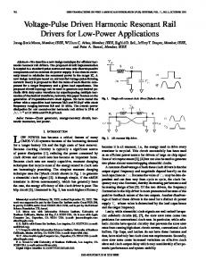
Stuck–open & stuck-on Faults
Stuck-open fault
Stuck-on fault
Dr. Ahmed H. Madian-VLSI
15
Multiple faults
Multiple faults are hard to detect Dr. Ahmed H. Madian-VLSI
16
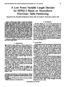
Single stuck-at-faults
The most common logic fault are stuck-at-0 and stuck-at-1 faults. Single stuck-at fault assumes, a single stuck-at fault occurs in a specific circuit. The objective of single stuck-at fault test is to determine the minimum number of test vectors to detect all possible stuck-at faults in a specific circuit regardless of the source of the fault. Single stuck-at fault is a pass-fail test. No faults means pass. Any fault means fail. Dr. Ahmed H. Madian-VLSI
17
Single stuck-at
If R is very small, the output F will be stuck-at-0 What will be the fault if R is relatively high but not ∞?
Slow pull-up (slow logic high transition).
Dr. Ahmed H. Madian-VLSI
18
Single stuck-at on logic level
1
Faulty Response
1 1
Ture Response
Test Vector
0
(1)
0 0 0
×
STUCK-AT-1
ASSUMPTIONS: 1. ONLY ONE LINE IS FAULTY. 2. FAULTY LINE PERMANENTLY SET TO 0 OR 1. 3. FAULT CAN BE AT AN INPUT OR OUTPUT OF A GATE. Dr. Ahmed H. Madian-VLSI
19
Test Vector Reduction
Since in single stuck-at fault test we do not care about determining the source/location/reason of the fault, equivalent faults should be detected and put in sets to reduce the number of test vectors to test the circuit. Examples of equivalent tests are:
Any input or output of OR gate s.a.1. Any input or output of AND gate s.a.0. Any input of NAND gate s.a.0 or output s.a.1. Any input of NOR gate s.a.1 and output s.a.0. Input of Inverter s.a.1/0 and output s.a.0/1.
In order to perform single stuck-at test for a circuit, every line segment should be considered individually. Dr. Ahmed H. Madian-VLSI
20
Example
Circuit with stuck-at-1 fault at x3. Find test vectors?
Dr. Ahmed H. Madian-VLSI
21
Step 1
Sensitize circuit. Find input values that produce a value on the faulty node that’s different from the value forced by the fault. For our S-A-1 fault above, want output of AND gate to be 0.
S-a-1 Dr. Ahmed H. Madian-VLSI
22
Step 2
Fault propagation. Select a path that propagates the faulty value to an observed output y
S-a-1 Dr. Ahmed H. Madian-VLSI
23
Step 3
Line justification. Find a set of input values that enables the selected path (backtracking).
S-a-1
Dr. Ahmed H. Madian-VLSI
24
Non-Testable Node Example
Node 8 is controllable but not observable. Example of circuits with poor controllability are decoders and circuits with feedback. Example of circuits with poor observability are memories such as RAMs and ROMs. Dr. Ahmed H. Madian-VLSI
25
Undetectable faults (logic redundancy)
F could be reduced to F = AB + AC Without reducing/optimizing the logic function, the logic implementation could have redundancy. This redundancy could result in having undetectable nodes since redundant nodes are not observable. Dr. Ahmed H. Madian-VLSI
26
Soft Errors
The most common soft error concerns arise from alpha particles and cosmic rays. In both cases, energetic external radiation hits the silicon substrate and creates free electron-hole pairs. These electron-hole pairs represent mobile charge that can migrate to the small storage nodes in the array and degrade the value stored in an SRAM for example. The charge caused by the radiation could flip the data value stored in the SRAM since the cell is designed to be as small as possible. Determining an SRAM array’s susceptibility to soft error is a complicated process. Dr. Ahmed H. Madian-VLSI
27
Ad-Hoc Testable Design Techniques
Partition-and-Mux Technique Partition the circuit and add Muxs could increase the accessible nodes and reduce the test patterns. Initialize Sequential Circuit To avoid starting the sequential circuit with a random state. Disable Internal Oscillators and Clocks To decouple logic faults from synchronization faults. Avoid Redundant Logic Redundant logic introduces un-testable nodes and reduce circuit testability. Avoid Delay-Dependant Logic Test generation engines does not consider delay dependent logic which make it assume it is circuit with output equal zero. Dr. Ahmed H. Madian-VLSI
28
Test structure
Ideally all possible combination of the input should be tested to cover all fault possibilities (Exhaustive test). However, for large circuits, this is going to huge amount of resources (time and money). In order to test such circuits, test patterns should be generated either deterministically (by choosing the important ones) or randomly. In addition, pipelined sequential circuit may require many clock cycles to generate the output which may require test pattern generator. Dr. Ahmed H. Madian-VLSI
29
Test Pattern Generation
Test pattern generation is either:
Deterministic pattern generation is performed for a specific fault (e.g. stuck-at). Advantage:
Deterministic pattern generation Random (Pseudorandom) pattern generation
Short test length Guaranteed fault coverage
Disadvantage:
Very computational expensive Need storage for test vectors Dr. Ahmed H. Madian-VLSI
30
Pseudo Random test Generation (PRTG)
Pseudorandom pattern generation is from its name random testing. Advantages:
Disadvantages:
Easy to generate No need for storage Suitable for Built-In Self Test (BIST) Long test length No coverage is guaranteed
PRPG can be done using Linear Feedback Shift Register (LFSR).
Dr. Ahmed H. Madian-VLSI
31
Output Response Analyzer (ORA)
The Output Response Analyzer (ORA) also called Signature Analyzer or Data Compactor can be done using Linear Feedback Shift Register (LFSR). Data compactor divides the polynomial representation of the test output data by a characteristic polynomial and then finds the reminder as the signature. Test data compression reduces the fault coverage. Dr. Ahmed H. Madian-VLSI
32
Design for Testability
Objective is to design the circuit while keeping in mind the requirements to test the circuit after manufacturing. In order to increase the efficiency of DFT, the following should be considered:
Time to generate test vectors. Test application time. Fault coverage. Overhead to improve testability Dr. Ahmed H. Madian-VLSI
33
Scan Based Testing Technique
In scan based design, the registers (F-F) are connected to form a long chain of shift-registers called scan path. In test mode, the scan-in signal is clocked into the scan path, and the output of the last F-F is scanned-out. In normal mode the scan-in path is disabled. Usually, low speed clock is used to test the circuit during the scan mode since logic rather than speed is the primary purpose of this test. Test Access Port (TAP)
Dr. Ahmed H. Madian-VLSI
34
References
Dr. magdy El-moursy lectures ICD’06, GUC. Design for Testability in Digital Integrated circuits, Bob Strunz, Colin Flanagan, Tim Hall, http://www.cs.colostate.edu/~cs530/digital_testing.pdf Tutorial: Delay Fault Models and Coverage, Proc 11th Int Conf VLSI Design, Page: 364, 1998, Ananta K. Majhi, Vishwani D. Agrawal http://www.cs.colostate.edu/~cs530dl/pap/majhiagrawal_delay.pdf R. Rajsuman, A.P.Jayasumana, Y.K.Malaiya, On Accuracy of Switch-Level Modeling of Bridging Faults in Complex Gates, 24th Conference on Design Automation, June 1987, pp. 244 - 250. http://www.cs.colostate.edu/~cs530dl/pap/acc_sw_level.pdf W.K. Al-Assadi, Y.K. Malaiya, A.P. Jayasumana, Faulty behavior of storage elements and its effects on sequential circuits, IEEE Trans VLSI, Dec. 1993, pp, 446 - 452 http://www.cs.colostate.edu/~cs530dl/pap/storage.pdf Y,K. Malaiya, A.P. Jayasumana, Qiao Tong, S.M. Menon, Enhancement of resolution in supply current based testing for large ICs, VLSI Test Symp., April 1991, pp.291 - 296. http://www.cs.colostate.edu/~cs530dl/pap/resolution_supply.pdf Y.K. Malaiya and R. Narayanaswamy,"Modeling and Testing for Timing Faulls in Synchronous Sequential Circuits," IEEE Design & Test, pp.62-74,1984 In library
Dr. Ahmed H. Madian-VLSI
35