SETIT 2007
4th International Conference: Sciences Of Electronic, Technologies Of Information And Telecommunications March 25-29, 2007 – TUNISIA
VHDL-AMS Behavioral Modeling and Simulation of M-QAM transceiver system Karim JABER, Ahmed FAKHFAKH and Nouri MASMOUDI Laboratoire d’Electronique et des Technologies de l’Information Ecole Nationale d’Ingénieurs de Sfax BP W, 3038 SFAX TUNISIE, Tel (+216) 74 274 088 - Fax: (+216) 74 275 595
[email protected] [email protected] [email protected] Abstract: The size, complexity and performances of modern wireless communication circuits are getting more and more challenging whereas marketing time and cost must be reduced as much as possible. In order to fill the current lack in CAD tools, this work is dedicated to the mixed simulation of complete communication systems driven by digital and digitally modulated RF signals. This paper describes a methodology for top-down design, modeling, and simulation of complete RF system using hardware description language VHDL-AMS (Very high speed integrated circuit Hardware Description Langage – Analog Mixed Signal). As application, we consider a complex M-QAM system (transmitter, channel, and receiver) and we show some details of VHDL-AMS implementation for each elementary block (sequence of bit, mixer, oscillator, filter, M-level, etc.). Using these behavioral blocks, we simulate our M-QAM system and evaluate system performance. We show that the results of VHDL-AMS simulations match both Agilent ADS results and theoretical calculations. The developed library of RF blocks is destinated to engineers who work on behavioral modeling and simulation of complete RF systems using hardware description languages. Key words: Modulation, digital, mixed, modelling, simulation, behavioral, VHDL-AMS, QAM, M-QAM.
INTRODUCTION As the demand for system-on-chip (SoC) implementations increases, the need to accurately model mixed-signal designs becomes more important. Digital designs have been highly automated, and the prevalence of top-down design is very strong in this area. In contrast, traditional analog RF designs are normally bottom-up, starting at the transistor level. Mixed-signal designers must then take a combination of hierarchical design approaches, and effort is being made to automate this design flow in a similar manner as seen for current digital systems. The overall goal is to provide designers tools to allow the combination of digital and RF models at the netlist level, creating a physical SoC model from which masks can be made for quick prototyping and fabrication. The ability to model and co-simulate digital and RF components together was made possible by the creation of
hardware description languages (HDLs) such as VHDL-AMS [IEE 99] and Verilog-A. That requires the development of high-level behavioral models for mixed-signal systems blocks. Later, the abstraction levels of these models can be reduced to more accurately model physical circuit implementations [NOR 04]. In this paper, we concentrate on VHDL-AMS behavioural modeling and simulation of complete RF systems, a quadrature amplitude modulation (MQAM) transceiver/receiver. We present a library of simple RF blocks that can be run in any HDL simulator with proper language support functionality. Any additional level of detail can be further added to these blocks, down to the circuit level inclusively [NIK 04]. For VHDL-AMS simulations, we use Simplorer 6.
We try here to achieve a generic modulator, which can be adjusted for a big variety of modulations and compatible with needs of telecommunications today.
When the receiver exploits knowledge of the carrier’s phase to detect the signals, the process is called coherent demodulation/detection [SKL 98]. Figure 2 shows a block diagram of a QAM coherent
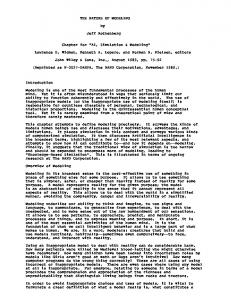
1. DESCRIPTION OF MIXED MODULATOR / DEMODULTEUR M-QAM 1.1. Modulator M-QAM The baseband equivalent representation, um(t), of the QAM signal can be expressed as u (t ) = ( AI + jAQ ) g (t ) m=1,2,…..,M (1) m
Where
m
m
A , A ∈ {±1∆,±3∆,...,±( M −1)∆} (∆ is a I m
Q m
constant whose value is determined by the average transmitted power). The baseband signal Sm(t), which is chosen from one of M possible signalling waveforms is given by:
s m (t ) = Re{ u m (t )e j 2πf t }= Am g(t) cos(2πf ct +θ m ) (2) c
fc is the intermediate carrier frequency. Alternatively, the bandpass QAM signal in (2) can be expressed equivalently in terms of its quadrature components as:
s m (t ) = AmI g(t) cos(2πfct) − AmQg(t) sin(2πfct)
(3)
This representation leads to the most common functional representation of the QAM modulator, which is shown in Figure 1. LPF
(R)
Binary sequence
(Rb)
cos(2πfct)
g(t)
sm (t)
LO
Constellation encoder
demodulator. Figure 2: Block diagram of a QAM coherent demodulator. At the receiver, the received high frequency signal is first down-converted to a lower intermediate frequency (IF) before being further processed. The demodulator performs the majority of its work at an intermediate or baseband frequency. The mixer in the coherent demodulator converts the IF signal to a baseband signal, by multiplying the incoming IF signal with a locally generated carrier reference and the product is passed through a lowpass filter (LPF). The LPF removes the high-frequency components and selects the difference component from the mixer output. These LPFs also perform as matched filters whose impulse responses are matched to the transmitted signal to provide the maximum signal-to-noise ratio (SNR) at their output. Then detectors decide which of the possible signal waveforms was transmitted from the output of the LPFs.
90°
(R)
LPF
A mQ
g(t)
-sin(2πfct)
Figure 1: Typical QAM modulator. First, the input binary baseband sequence with bit rate Rb bits/second is encoded into two quadrature M -level pulse amplitude modulation (PAM) signals, each having a symbol rate of R= Rb/ K symbols/second ( K = log2M ). These two components of I and Q are then filtered by pulse-shaping lowpass filters (LPFs), g(t) , to limit the transmission bandwidth. Finally the quadrature signals modulate the I and Q carriers for transmission. The transmitted bandpass signal Sm(t) , which is the summation of all symbols represented by the M possible signalling waveforms for QAM [PRO 95], [CHE 04].
2. VHDL-AMS IMPLEMENTATION OF MQAM SYSTEM Our work is focused on the development of a complete VHDL-AMS library containing high level descriptions of the most commun modulation and demodulation techniques like ASK, PSK, QPSK, and QAM. We will only focused in this paper on the presentation of a generic M-QAM modulator/demodulator. A highly ideal system, modeled after the theoretical QAM system, is implemented in VHDL-AMS. To better manage the number of components involved in this design, the code hierarchy in Figure 3 is implemented. Each block contains the components needed to perform its intended function. The QAM system wrapper is used to initialize variables concerning only the RF system: transmitter, and receiver.
1.2. Demodulator M-QAM Since the information is carried in the phase and amplitude of the modulated carrier for the QAM signal, the receiver is assumed to be able to generate a reference carrier whose frequency and phase are identical to those of the carrier at the transmitter.
. Binary sequence
Transmitter
Channel
Receiver
‘M-QAM’
Figure 3: Basic M-QAM code hierarchy of VHDLAMS model. 2
2.1.2. M-level QAM 2.1. Transmitter M-QAM The transmitter block diagram is shown on Figure 4.
In M-level QAM the bit data is suitably assembled into N symbols (M=2N) and each symbol transmitted by a carrier wave having a unique amplitude and phase. The duration of each symbol determines the bandwidth of the QAM signal. Fig.6 shows a M-level constellation where each dot represents the position of the phasor relative to the intersection of the axes marked I (for in phase) and Q (for Quadrature) [HAN 90]. The phasors of the M-level constellation may be decomposed into N/2 independent N-level AM signals that are transmitted on quadrature components of the same carrier.
Figure 4: Transmitter bloc diagram. The architecture of the modulator can be separate in several functional blocks, witch can be studied separately: -The block of serial to parallel: the binary sequence (serial data) is converted to N-bit (M=2N). -The generation block of M-levels (modulator i(t)/q(t)) produces the two ways In-phase i(t) and Quadraturephase q(t). It integrates a digital to analog converter -The modulation block produces the modulated signal. The goal is to support a coding adapted to several types of modulations. The coder will accept modulations QPSK and 4-QAM until 256-QAM.
Each AM carrier is transmitted with an amplitude of either -(N-1)d,……, -3d, -d, d, 3d,…….., (N-1)d, where d is the coordinate spacing shown in Fig.6. The N-level AM components are binary encoded using N/2 Gray coded bits for each level. For example, the 4-level AM components of 16-QAM are binary encoded using two Gray coded bits for each level; Gray codes 01, 00, 10 and 11, are assigned to levels 3d, d, -d and 3d, respectively [YEA 03].
Q 01
2.1.1. Serial to parallel The binary input stream is subdivided into block of N bits, called symbols, and each symbol is represented by one of M=2N pulse amplitude values. The incoming N bits are considered in groups of N bits. The block diagram of a M-QAM transmitter is shown on Figure 4. The input binary data are divided into N channels: I0, I1…. I(N/2)-1, and Q0, Q1,……, Q(N/2)-1. The bit rate in each channel is fb/N. N bits are serially clocked into the serial-to-parallel block. The serial to parallel block used shift register to N bits and N latch D shown on Figure 5.
Origin
00
-3d
Origin
11
10
-d
10
d
00
3d
I
01
M-QAM (M=16)
11
Q 3d d
-3d
d
d
3d
I
-d -3d I0Q0I1Q2
Modulation QAM of 2N states Horloge T
Shift register to N bits
Binary sequence
Figure 6: M-ary QAM constellation, M=16.
Horloge NT
Latch D
Figure 5: Serial to parallel block.
The mapping of the bits into symbols is frequently done in accordance with the Gray code which helps to minimize the number of bit errors occurring for every symbol error. Because Gray-coding is given to a bit assignment where the bit patterns in adjacent symbols only differ by one bit [BAT 99], this code ensures that a single symbol in error likely corresponds to a single bit in error. Finally, we mixed the I channel with cos(ωct) and Q channel with sin(ωct). The resulting signals are then summed and amplified by an ideal power amplifier. 3
2.2 Receiver
gen_bit.val
The receiver diagram block is depicted on Figure 7. The signal is first amplified and then down converted by mixing it with the sine and cosine of the carrier frequency. Then, the obtained signals passe through low-pass filters, creating the reconstructed I and Q channels. The I and Q channels output from the demodulator are then digitized in N bit and passed to the parallel to serial converter, where they are sampled using the recovered symbol clock, hard limited, and output serially from the binary sequence.
2
inphase.val
-2
2
quadrature.val
-2
2
inp_estime.VAL
-2
2
quad_estime.VAL
-2
0
2u
4u
6u
10u t [s]
8u
Figure 9(a): Inphase and Quadrature for 4QAM(M=4). 4
Inphase.input0
0 -4
4
LPF
Quadrature.input0
0
cos(2πfct)
-4
A/D
sm (t)
2
Parallel to serial
LO
I_Filter.VAL
0 -2
2
90°
Q_Filter.VAL
0
-sin(2πfct)
-2
0
25u
20u
15u
10u
5u
29u t [s]
LPF
Figure 7: Block diagram of VHDL-AMS M-QAM receiver.
Figure 9(b): Inphase and Quadrature for 16QAM (M=16). 10
Inphase.input0
0 -10
10
3. SIMULATION RESULTS
Quadrature.input0
0 -10
The VHDL-AMS description developed for the transmitter/receiver M-QAM system is based on the principe detailed above. The obtained high level model is generic and gives the possibility to the user to choice the M-QAM modulation technique. Figure 8 shows four waveforms. Digital data, inphase, quadrature and the 4-QAM modulated signal obtained after the transmitter model simulation.
5
I_Filter.VAL
0 -5
4
Q_Filter.VAL
0 -4
0
20u
15u
10u
5u
26u t [s]
Figure 9(c): Inphase and Quadrature for 64-QAM (M=64). Figure 10 shows 4-QAM the constellation in the transmitter and in the receiver (after filtering).
gen_bit.val 2
inphase.val
-2
4_QAM
1.3
2
quadrature.val
1
-2
2
signal_mod.val
0.5
-2 0
0
1u
2u
3u
4u
5u
6u t [s]
-0.5
-1 -1.3
Figure 8: 4-QAM Transmitter.
-2
-1.5
-1
-0.5
0
0.5
1
1.5
2
Figure 9 (a,b,c) shows the signals I and Q in the transmitter, I and Q channels in the receiver (after filtering) respectively for 4 QAM, 16 QAM and 64 QAM. We can see that in all cases we receive the same transmitted information.
Figure 10: Constellation 4-QAM (M=4) 4
We have shown that we are able to obtain a transient response, a constellation or a spectrum of the modulated and demodulated signals after the simulation of our VHDL-AMS description. All these results allow to study and to optimize the transmitter/receiver at a high level of design which constitutes an important step in the top-down hierarchical design flow. REFERENCES
With the generic model that we have developped and simulated, we can draw the spectrum of the modulated signal. Figures 11(a), (b) and (c) represent respectively spectrums of the modulation 16 QAM, 32 QAM and 64 QAM -0.17Meg
5.00Meg
10.00Meg
15.00Meg
20.00Meg
25.00Meg
1.003
sum1....
0.750
0.750
0.500
0.500
0.250
0.250
0
0 -0.17Meg
5.00Meg
10.00Meg
15.00Meg
20.00Meg
25.00Meg
(a) -0.25Meg 1000.0m
5.00Meg
10.00Meg
15.00Meg
20.00Meg
25.02Meg sum1....
750.0m
750.0m
500.0m
500.0m
250.0m
250.0m
0
0 -0.25Meg
5.00Meg
10.00Meg
15.00Meg
20.00Meg
25.02Meg
(b)
[BAT 99] A. Bateman, Digital Communications: Design for the real world, Addison-Wesley Longman Limited, New York, NY, 1999. [CHE 04] J. Chen, “CARRIER RECOVERY IN BURSTMODE 16-QAM,” thesis, University of Saskatchewan, June 2004. [HAN 90] L. Hanzo, R. Steele, and P.M. Fortune “A Subband Coding, BCH Coding, and 16-QAM System for Mobile Radio Speech Communications,” IEEE Transactions on Vehicular Technologies, 1990. [IEE 99] “VHDL Analog and Mixed-Signal Extensions: IEEE standard 1076.1-1999,” [NIK 04] P. Nikitin, E. Normark, C. Wakayama, and R. Shi “VHDL-AMS modeling and simulation of a BPSK transceiver system,” Proceedings of IEEE International Conference on Circuits and Systems for Communications, 2004. [NOR 04] E. Normark, L. Yang, C. Wakayama, P. Nikitin, and R. Shi “VHDL-AMS Behavioural Modeling ad Simulation of a π/4 DQPSK transceiver system,” 2004. BMAS 2004. Proceedings of the Fifth IEEE International Workshop on, 10-12 Oct. 2004. [PRO 95] J. G. Proakis, Digital Communications, McGraw-Hill Inc., New York, NY, 1995 (Third Edition).
-0.24Meg
5.00Meg
10.00Meg
15.00Meg
20.00Meg
25.02Meg
1.002
sum1....
0.750
0.750
0.500
0.500
0.250
0.250
0
[SKL 98] B. Sklar, Digital Communications: Fundamentals and Applications, PrenticeHall Inc., Englewood Cliffs, NJ, 1998. [YEA 03] Bee Leong Yeap, Choong Hin Wong, and Lajos Hanzo, “Reduced Complexity In-Phase/QuadraturePhase M-QAM Turbo Equalization Using Iterative Channel Estimation,” IEEE Transactionson Wireless Communications, VOL. 2, NO. 1, JANUARY 2003.
0 -0.24Meg
5.00Meg
10.00Meg
15.00Meg
20.00Meg
25.02Meg
(c) Figure 11: Spectrum of ((a):16 QAM, (b):32 QAM, (c): 64 QAM) We can see that when the number of bits increases (or symbols), the spectral clutter increases.
4. CONCLUSION In this paper, we described a methodology for modelling and simulation of complete RF system using VHDL-AMS. As a demonstration example, we considered an M-QAM system. We simulated and evaluated system performance and a high level of description. 5