tester approach can reduce the manufacturing costs. The FPGA is a programmable logic device (PLD) that can be programmed to perform any digital tasks.
Proceedings of the 6th WSEAS International Conference on Instrumentation, Measurement, Circuits & Systems, Hangzhou, China, April 15-17, 2007
VHDL Modelling of the Open Short Tester W. L. Pang, K. W. Chew, Florence Choong, C.L. Chan Faculty of Engineering Multimedia University Cyberjaya, Selangor MALAYSIA http://www.mmu.edu.my Abstract: - IC (Integrated Circuitry) testing requires the very advanced and sophisticated Advance Test Equipment (ATE) that costs multi million USD. The cost of IC testing is increasing yearly and it will exceed the cost of manufacturing in future. The manufacturers are interested to lower down the manufacturing cost. Low cost tester is one of the options to reduce the manufacturing cost. The low cost FPGA realization of Open/Short Test on IC is introduced to reduce the IC test cost. The open short test is selected, because it is the first IC test. The Very High Speed Integrated Circuit Hardware Description Language (VHDL) is used to model the Open/Short Test on IC and the design is capable to perform the open/short test. Key-Words: - open short test, VHDL modelling, IC tester
1 Introduction
The cost of an integrated circuit (IC) includes the design cost, the manufacturing cost and the testing cost. The IC testing becomes more challenging and complex when the IC become smaller and more transistors accommodated in a single IC. A very advance and sophisticated ATE that costs multi million USD is required to perform the IC testing. The manufacturers always try to reduce the manufacturing costs to control the IC selling price. The low cost FPGA realization of open/short tester approach can reduce the manufacturing costs. The FPGA is a programmable logic device (PLD) that can be programmed to perform any digital tasks. The implementation cost of the FPGA is low because the FPGA is reprogrammable and has very high density of logics available for programming and also acts as storage elements. A prototype of FPGA open/short tester is designed. The prototype tester can measure 4 IC pins only to perform the open short test, because the same method can be duplicated to support more test pins. It can be easily duplicated to measure 8 IC pins, 16 IC pins or even 100 IC pins by increasing the number of hardware designed. The FPGA open/short tester is more cost effective compare to the Agilent technologies and Tektronix testers.
2 ESD Test
The IC fabrications are dominated by the advanced Complementary Metal Oxide Semiconductor
(CMOS) technology because the CMOS IC will have low static power consumption, high noise margin and high integration. However the MOS devices are particularly vulnerable to ESD event [1]. The ESD phenomena become a serious problem for IC products fabricated by deep-submicron CMOS technologies. Electrostatic discharge (ESD) refers to the sudden transfer (discharge) of static charge between objects at different electrostatic potential [2]. It belongs to the family of electrical problems known as electrical overstress (EOS). Other members of EOS family include lighting and electromagnetic pulses (EMP). ESD/EOS is responsible for nearly 40% of the failed integrated circuits (ICs) returned by customer [1]. The three primary ESD test methods are HBM (Human Body Model), MM (Machine Model) and CDM (Charge Device Model). The models used to perform device testing cannot duplicate the full spectrum of all possible ESD events. But these models have been proven to be successful in reproducing over 95% of all ESD field failure signatures [3].
3 Open Short Test
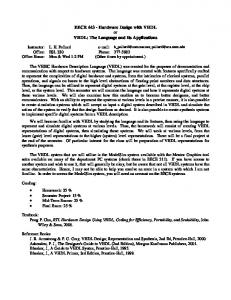
The PN junction diodes are used as the ESD clamp device. The ESD clamp device is shown in Fig 1. The bonding pad is used to connect the internal circuits of an IC to the outside world and between the bonding pad and Input/Output (I/O) pins, there will be electrostatic discharge (ESD) clamp circuit to protect the IC from the ESD event.
34
Proceedings of the 6th WSEAS International Conference on Instrumentation, Measurement, Circuits & Systems, Hangzhou, China, April 15-17, 2007
The simple ESD clamp circuit consists of a pair diodes connect in series as shown on Fig 1. Open/short circuit test on IC is performed by determine the whether both diodes which connected in series are function correctly or not. The diodes pair is used to perform the open short test.
• •
The PMU clamps the voltage at -5.0V. The upper PMU test limit is set to fail the short test if the measured result is > -0.2V. • The lower PMU test limit is set to fail the open test if the measured result is < -1.5V. Fig 3 shows the configuration to test the lower ESD diode. The PMU is clamped the voltage at 5V in order to test the upper diode. The upper diode will be in forward bias and the lower diode will be in reverse bias because the VDD now is grounded (0V). The 100uA current will flow through the good upper diode and give a voltage drop about 0.4-0.7V across the upper diode.
Fig 1: The diodes serve as the ESD clamp device A precision measurement unit (PMU) is used to perform the open/short test. The PMU is the DC measurement devices. It clamps the voltage and current into a specific limited range of voltage and current. It also can set the upper and lower limit of the measure value to determine whether the device under test (DUT) is pass or fail the open/short test. It will forces the current and measures the voltage or vice versa. The following steps are used to test the upper ESD diode: • Ground all the pins including VSS and VDD • The PMU is used to force a positive current of ~100µA to one IC pin at a time. • The PMU clamps the voltage at +5.0V. • The upper PMU test limit is set to fail the open test if the measured result is >1.5V. • The lower PMU test limit is set to fail the short test if the measured result is