Hindawi Shock and Vibration Volume 2017, Article ID 3548360, 11 pages https://doi.org/10.1155/2017/3548360
Research Article Vibration Control of Tower Structure with Multiple Cardan Gyroscopes Haoxiang He,1,2 Xin Xie,1 and Wentao Wang1 1
Beijing Key Laboratory of Earthquake Engineering and Structure Retrofit, Beijing University of Technology, Beijing 100124, China Beijing Collaborative Innovation Center for Metropolitan Transportation, Beijing 100124, China
2
Correspondence should be addressed to Haoxiang He;
[email protected] Received 14 October 2016; Accepted 14 December 2016; Published 5 January 2017 Academic Editor: Elena Dragomirescu Copyright © 2017 Haoxiang He et al. This is an open access article distributed under the Creative Commons Attribution License, which permits unrestricted use, distribution, and reproduction in any medium, provided the original work is properly cited. Tower structure is sensitive to hurricane and earthquake, and it is easy to generate large deflection and dynamic response. The multiple cardan gyroscope has two rotational degrees of freedom, which can generate strong moments to constrain the two horizontal orthogonal deflections if the rotor operates in high speeds, so the structural dynamic responses can be decreased. Hence, the method of dynamic control of the tower structure under wind load and earthquake action is proposed by using the multiple cardan gyroscopes as the dampers. The dynamic mechanism and the fixed axis principle of the multiple cardan gyroscope are introduced, and the dynamic equation of the gyroscope is established. The damping mechanism of the gyroscope is also described. For the tower structure equipped with the multiple cardan gyroscope dampers, the multidimensional control equation considering torsion effect is established, and the equivalent state space equation is presented. Taking a TV Tower with a number of gyroscope dampers as an analysis example, the structural dynamic responses and damping performance under fluctuating wind loads and earthquake action is studied. The results show that the multiple cardan gyroscope dampers with suitable parameters can effectively decrease the structural vibration in horizontal directions and torsional direction.
1. Introduction Tower structure is a type of slender and lofty structure, whose altitude is much larger than its width, often by a significant margin. Since the cross section of tower structure is relatively smaller, the lateral load plays an important role on the structural dynamic responses [1, 2]. Because the form of tower structure is tall and beautiful, it is widely used in the field of communication facilities, power facilities, chemical engineering, and so forth. Compared with the common building structure, the horizontal stiffness of tower structure is weak, so it is sensitive to hurricane and earthquake, and it is easy to generate large static deflection and dynamic response [3]. Therefore, the research on the dynamic characteristics and vibration control of tower structure has been increasingly emphasized. In order to realize the hazard protection of structure, the tower structures should have enough capacities to dissipate energy. The dynamic performance of the traditional tower is improved by enhancing the design parameter such as stiffness
and ductility, but the structure designed by normal methods still has not enough ability during strong earthquakes. Therefore, the traditional design methods have been improved by new technology such as damping control or shock absorbers. There are various means to realize the structural damping control. As one of the most effective tool of passive structural vibration control technologies, seismic isolation enables the building structure to survive a potentially devastating seismic impact through isolation bearings with large damping and flexibility [4, 5]. Based on the mechanism of tuned vibration control, the tuned mass damper is usually installed on the top of the structure to reduce the amplitude of mechanical vibrations [6, 7]. In some frame building structures, the energy dissipation braces which connect the two consecutive layers of building and incorporating suitable devices are purposely designed to dissipate a large amount of energy [8]. With the same features and functions, the fluid viscous damper and the metallic damper are also used in various structures [9, 10].
2 Due to the fact that the tower structure is prone to overturn if the isolation bearings are installed on the base, the seismic isolation technology is not the best option [11]. Because of the limited space, large dampers are not suitable for installation in the tower structure. The current devices mainly used in the vibration control of tower structures include viscous damper, tuned mass damper, and tuned liquid damper. The mechanism of these vibration reduction devices is definite, and it can achieve certain effect of vibration control through optimization analysis and standard production and installation. The tower structure vibration is mainly based on the first-order mode, so the optimal control position is usually on the top. However, the top location of the tower is flexible and internal space is limited, and the actual applicability of tuned damper is usually difficult to achieve owing to the huge volume of the damper [12]. To solve the above problems, it is necessary to be develop new type of the damping devices to effectively protect the safety of the tower structure in other ways. Gyroscope is a kind of mechanical device to judge and keep directions, which is designed based on the theory of conservation of angular momentum [13]. The gyroscope is mainly composed of gyro rotor, rotation shaft, frame, and other accessories. When the gyro rotor on the axial center rotates at high speed, the inertia force and the resistance force will be produced, and the rotation axis of the gyro rotor points to a fixed direction, this property is known as fixed axis [13–15]. Gyroscope is widely applied in aerospace, microelectronics, and mechanical control, and the effect is notable, especially when the active control scheme is adopted [16–18]. If the gyroscopes are installed on the building structure, it is apparent that the gyroscopes will generate restoring force and flexural moment to keep the initial direction when the structures vibrate under external dynamic actions, and the gyroscopes play the role of damper and the control effect will be obvious if the gyro rotor rotates in higher speed. Wang and Liu [19] have proposed the method of using the single degree of freedom gyroscope to control the structure random vibration, but this method is simple and cannot realize the multidirection vibration reduction. Moon et al. [20] have investigated the effectiveness of the gyroscope system for active seismic protection of flexible structures employing LQG control algorithms, and the simulation results show that gyroscope system has the possibility of reducing the vibration. However, only the simple building structure and active control is studied in above research, it is necessary to intensively study the performance of gyroscope damper for vibration reduction on tower structures or highrise structures, and the passive control effect should also be verified. In view of the characteristics of the gyroscope and previous research results, multiple cardan gyroscope is introduced as a new damper to reduce the bidirectional horizontal vibration. When the structure is subjected to wind or strong earthquake, the internal rotor damper can rotate at high speed, the fixed axis gyro can provide the reverse moment to decrease the two horizontal deflection of the structure, so the overall damper will dissipate the external dynamic energy, and then the safety of the structure is improved.
Shock and Vibration Z
Inner ring Outer ring
Y X Rotor
(a) Prototype and composition of gyroscope z
Structure
Rotor
x
Outer ring Inner ring
y
(b) gyroscope damper
Figure 1: Composition diagram of multiple cardan gyroscope.
In this paper, the mechanics principle of the multiple cardan gyroscope, that is, gyroscope with two DOFs, is introduced, and the dynamic control equations of the structure with the multiple cardan gyroscopes are established. The vibration reduction effect of the multiple cardan gyroscope damper on tower structure is studied. The results show that the reasonably arranged gyro dampers can effectively reduce the horizontal and torsional responses of the tower structure when it is subjected to wind and earthquake.
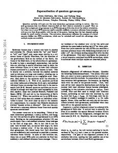
2. Gimbal Gyroscope Mechanics and Gyroscope Damper The multiple cardan gyroscope mainly comprises a gimbal bracket and a rotor, as shown in Figure 1. The gimbal bracket is composed of an outer ring and an inner ring, and it is the mechanical device used for supporting the gyroscope rotor. The outer ring is installed on the supporter or the structure, and the inner ring is installed on the outer ring, and the rotor or other supporting bodies are arranged on the inner ring.
Shock and Vibration The rotary axis of the outer ring, the inner ring, and the rotor is delivered at a point O, namely, the center of the gimbal bracket support. The outer ring, inner ring, and rotor around their axis of rotation angle 𝛼, 𝛽, and 𝜓 are cardan angle, and the outer ring, inner ring, and the rotor are, respectively, the physical coordinate systems 𝑒1 , 𝑒2 , and 𝑒3 . The 𝑒2 is usually called the LecA coordinate system. It is the principal axis of the inner ring and the axis symmetric rotor but does not participate in the high-speed rotation of the rotor; therefore, 𝑒2 is often used as the reference coordinate system on the dynamic calculation. From the above basic knowledge, it is clear that the two-degree-of-freedom gyroscope mainly consists of three rigid bodies. The first one is the external ring with onerotational-degree-of-freedom, the motion can be represented by a generalized angle coordinate which rotates around the outer ring. The second rigid body is the internal ring with two rotational degrees of freedom, and its movement can be described by two generalized coordinates which rotate around the external ring axis and the internal ring axis, respectively. The third rigid body is the rotor with threerotational-degree-of-freedom, the corresponding motion can be represented by three generalized coordinates that rotates around the rotation axis, external ring axis, and the internal ring axis, respectively. According to the property of fixed axis, a multiple cardan gyroscope can be used as a damper to control the structural deflection and dissipate energy. Thus, the cardan gyroscope damper consists of a gyro outer ring which can rotate around the horizontal axis of structure and a gyro inner ring rotates around the horizontal axis which is orthogonal to the abovementioned horizontal axis, the gyro rotor which rotates by the electric power and the electric motor. There are one internal ring and one external ring, so the gyroscope in the damper has two rotational degrees of freedom. Hence, the gyro device can rotate in a certain angular velocity steadily under dynamic action, trying to keep its axis relative to the inertial space azimuth invariant properties, and the resistance moment can be generated in order to counteract the two types of horizontal displacement, which can decrease the structural horizontal displacement or deflection. The construction diagram of the cardan gyroscope damper is shown in Figure 1. In order to investigate the effectiveness of the gyroscope damper in the vibration reduction, the dynamic equation should be established and the dynamic analysis can be carried out. In view of this demand, the gyroscope mechanics are firstly introduced and discussed. For a multiple cardan gyroscope, the inertial reference system is set as 𝑒0 , and the principal axis coordinate system of the outer ring, the inner ring, and the rotor is set as 𝑒1 , 𝑒2 , and 𝑒3 , respectively; then the rotary shafts of the outer ring, the inner ring, and the rotor are expressed as 𝑒11 , 𝑒22 , and 𝑒33 , respectively. Due to the fact that the rotor is an axial symmetry, the symmetry axis is coincident with 𝑒33 or 𝑒32 , which is called the polar axis of the gyroscope. The rotational angular velocity of each component can be expressed with cardan angle; that is, for the outer ring, 𝜔1 = 𝛼𝑒̇ 1 1 , for the
3 M1 Structure
L1
Outer ring
M2 L2
Inner ring
M3 L3
Rotor
Figure 2: Composition diagram of multiple cardan gyroscope.
inner ring, 𝜔2 = 𝛼𝑒̇ 1 1 + 𝛽𝑒̇ 2 2 , and for the rotor, 𝜔3 = 𝛼𝑒̇ 1 1 + 𝛽𝑒̇ 2 2 + 𝜑𝑒̇ 3 2 . The axis principal inertia moment of each component relative to the support center 𝑂 is as follows: for the outer ring it is 𝐴 1 , 𝐵1 , and 𝐶1 ; for the inner ring it is 𝐴 2 , 𝐵2 , and 𝐶2 ; for the rotor it is 𝐴 3 , 𝐵3 , and 𝐶3 . As shown in Figure 2, the resultant moment relative to point O on each component is as follows: for the outer ring, the value is 𝑀1 + 𝐿 1 − 𝐿 3 ; for the inner ring, the value is 𝑀2 + 𝐿 2 − 𝐿 2 ; for the rotor, the value is 𝑀3 + 𝐿 3 . According to the moment of momentum theorem, the dynamic equations when the rotor, the inner ring-rotor, and the outer ring-inner ring-rotor rotate around the rotary axis of the rotor, the inner ring, and the outer ring, respectively, are given by 𝐶3
𝑑 (𝜑̇ + 𝛼̇ sin 𝛽) = 𝑀33 + 𝐿 23 , 𝑑𝑡
(𝐵2 + 𝐴 3 ) 𝛽̈ + (𝐴 2 + 𝐴 3 − 𝐶2 ) 𝛼̇ 2 cos 𝛽 sin 𝛽 − 𝐶3 (𝜑̇ + 𝛼̇ sin 𝛽) 𝛼̇ cos 𝛽 = 𝑀22 + 𝑀32 + 𝐿 23 ,
(1)
(2)
𝑑 {[𝐴 1 + 𝐶2 + (𝐴 2 + 𝐴 3 − 𝐶2 ) cos2 𝛽] 𝛼̇ 𝑑𝑡 + 𝐶3 (𝜑̇ + 𝛼̇ sin 𝛽) sin 𝛽} = 𝑀11 + (𝑀21 + 𝑀31 )
(3)
⋅ cos 𝛽 + (𝑀23 + 𝑀33 ) sin 𝛽 + 𝐿 11 , where 𝑀1𝑗 (𝑗 = 1, 2, 3) and 𝐿 1𝑗 (𝑗 = 1, 2, 3) are the projection of 𝑀1 and 𝐿 1 on 𝑒1 , and 𝑀2𝑗 , 𝑀3𝑗 , 𝐿 2𝑗 , and 𝐿 3𝑗 are the projection of 𝑀2 , 𝑀3 , 𝐿 2 , and 𝐿 3 on 𝑒2 , respectively. After the termination of the rotor drive, there are two kinds of steady-state motion, which are, respectively, corresponding to the two different constraint conditions of the driving motor, namely, the ideal constraint and the constant speed constraint. The driving moment of the former is balanced with the damping torque and the resultant force moment is zero; the latter maintains a constant speed of the rotor relative to the inner ring. For the ideal constraint condition, the right item of (1) is zero, so the new equation can be obtained by the first integral method as 𝜑̇ + 𝛼̇ sin 𝛽 = 𝜔0 ,
(4)
in which the integral constant 𝜔0 is the steady value of the absolute speed of the rotor.
4
Shock and Vibration
Substituting (4) into (2) and (3), the steady-state motion equation can be derived as follows: 𝑑 [𝐼 (𝛽) 𝛼̇ + 𝐻0 sin 𝛽] = 𝑀1 , 𝑑𝑡
(5)
1 𝐵𝛽 − 𝐼̇ (𝛽) 𝛼̇ 2 − 𝐻0 𝛼̇ cos 𝛽 = 𝑀2 , 2
(6)
where 𝐼(𝛽) = 𝐴 1 + 𝐴 2 + 𝐴 3 + 𝐾sin2 𝛽, 𝐾 = 𝐶2 − 𝐴 2 − 𝐴 3 , 𝐵 = 𝐵2 + 𝐴 2 , 𝐻0 = 𝐶3 𝜔0 , 𝑀1 = 𝑀11 + (𝑀21 + 𝑀31 ) cos 𝛽 + (𝑀13 + 𝑀23 ) sin 𝛽 + 𝐿 11 , and 𝑀2 = 𝑀22 + 𝑀32 + 𝐿 22 . For constant speed constraints, a similar result can also be got, only the definition of K is modified as 𝐾 = 𝐶2 + 𝐶3 − 𝐴 2 − 𝐴 3. Due to the stability of the high-speed rotating gyroscope, the rotational angular velocity of the universal may be written as (7) 𝐼 (𝛽) 𝛼̈ + (𝐻 cos 𝛽) 𝛽̇ = 𝑀 , 0
1
𝐵𝛽̈ − (𝐻0 cos 𝛽) 𝛼̇ = 𝑀2 .
(8)
If the deflection angle of outer ring 𝛼 and the deflection angle of the inner ring 𝛽 keep in a stable position 𝛼0 and 𝛽0 , respectively, and the deviation values and the derivatives higher than the second can be ignored, (7) and (8) can be changed into a linear equation group 𝐴𝛼̈ + 𝐻𝛽̇ = 𝑀1 ,
(9)
𝐵𝛽̈ − 𝐻𝛼̇ = 𝑀2
(10)
in which 𝐴 and 𝐻 are defined as 𝐴 = 𝐴 1 + 𝐴 2 + 𝐴 3 + 𝐾sin2 𝛽0 and 𝐻 = 𝐻0 cos 𝛽0 . If the rotor speed is very high and the moment of force changes slowly, the two-order derivatives 𝛼̈ and 𝛽̈ can be omitted and (9) and (10) can be simplified as a first-order linear differential equation. For the actual gyroscope damper, the principal moments of inertia of the outer ring, the inner ring, and the rotor which rotate the coordinate system of the base 𝑥-, 𝑦-, and 𝑧-axis are, respectively, 𝐽𝑥0 , 𝐽𝑦0 , 𝐽𝑧0 , 𝐽𝑥1 , 𝐽𝑦1 , 𝐽𝑧1 , 𝐽𝑥𝑅 , 𝐽𝑦𝑅 , and 𝐽𝑧𝑅 . When the rotor rotates with absolute high speed 𝜔0 , the gyro angular momentum constant 𝐻0 = 𝐽𝑧 𝑅𝜔0 , which means the rotor steady-state value of absolute angular momentum. Set 𝛼 and 𝛽 as the corner of outer frame and internal frame, according to the theory of moment of momentum, based on (9) and (10), the steady-state dynamic equation of gyroscope under ideal constraints is [𝐽𝑥0 + 𝐽𝑧1 + 𝐽𝑧𝑅 + (𝐽𝑥1 + 𝐽𝑥𝑅 − 𝐽𝑧1 − 𝐽𝑧𝑅 ) cos2 𝛽] 𝛼̈ + (𝐻0 cos 𝛽) 𝛽̇ = 𝑀𝑥 , (𝐽𝑦1 + 𝐽𝑥𝑅 ) 𝛽̈ − (𝐻0 cos 𝛽) 𝛼̇ = 𝑀𝑦 .
(11) (12)
When the outer frame and inner framework rotate at a certain rotating angular velocity, (11) and (12) can be simplified as (13) (𝐻 cos 𝛽) 𝛽̇ = 𝑀 , 0
𝑥
− (𝐻0 cos 𝛽) 𝛼̇ = 𝑀𝑦 .
(14)
According to the above derivation and the characteristic of motion equations, it is clear that greater moment will be produced by increasing the rotational speed and the moments of inertia of the inner ring and the outer ring. If the rotational speeds of the outer ring and the inner ring increase, the effective resistance moment will increase and the displacement is reduced more dramatically according to the property of fixed axis of gyroscope. As the moments of inertia of the rings are related to the mass and the radius of gyration, the damping effect can be effectively enhanced if the mass and the radius of gyration increase. Since the radius of gyration is not easy to set to a larger value, the actual optimum values for control effect mainly include the rotational speed and the mass of the outer ring and the inner ring. The fixed axial moment provides the external force for structure to rebound to the initial equilibrium state and reduce the structural deformation. In addition, in the case of the total mass is constant, the torque value can be significantly enhanced only by increasing the gyro plane size or the rotation speed. Hence, the gyro damper is particularly suitable for installing on the top of the tower structure since it has larger outer space.
3. Dynamic Model of Structure with Gyroscope Dampers In order to study the damping effect of the structure equipped with multiple cardan gyroscopes, the actual tower structure can be equivalent to a multidegree-of-freedom system with multiple lumped mass. It assumes that the gyro dampers are installed on the multipositions of the tower structure which has n equivalent lumped mass and the motion in two horizontal directions and around the vertical axis can be controlled. The dynamic equation of the structure system under multidimensional earthquake is given by MÜ + CU̇ + KU = −MÜ 𝑔 (𝑡) + F (𝑡)
(15)
in which, M, C, and K are the global mass matrix, the global damping matrix, and the global stiffness matrix of the dynamic system, respectively, and the dimension of all the matrix is all 3𝑛 × 3𝑛. U = [U𝑥 , U𝑦 , U𝜃 ]𝑇 = {𝑢𝑥1 , . . . , 𝑢𝑥𝑛 , 𝑢𝑦1 , . . . , 𝑢𝑦𝑛 , 𝑢𝜃1 , . . . , 𝑢𝜃𝑛 }𝑇 , which is the displacement vector of the 3D structure system. 𝑥, 𝑦, and 𝑧 represent one horizontal direction and the other orthogonal horizontal directions and the vertical = [Ü 𝑥𝑔 (𝑡), Ü 𝑦𝑔 (𝑡), Φ̈ 𝜃𝑔 (𝑡)]𝑇 , which direction. Ü 𝑔 (𝑡) is the dynamic loading or acceleration excitation. F(𝑡) = {0, . . . , 𝐹𝑥 (𝑡), 0, . . . , 𝐹𝑦 (𝑡), 0, . . . , 0}𝑇 , which is the equivalent concentrated force of the moment of the multiple cardan gyroscopes, and the applied positions are the same as the locations of the gyro dampers. Because the coupling damping matrix of the tower structure and the gyro dampers is not orthogonal, and it belongs to the nonclassical damping, so (13) cannot be decoupled directly by the real modal transformation method and the time history analysis cannot be carried out. To solve the above problems, the state space method can be adopted and the higher order ordinary differential equation of the
Shock and Vibration
5 157.50 m [3, 0.35]
system can be transformed into one first-order differential equation in the composition of state variables by introducing adequate state vectors. First, the variable Ü 𝑔𝑒 (𝑡) = (I − F(𝑡)/MÜ 𝑔 (𝑡))Ü 𝑔 (𝑡) is defined, in which I is unit matrix. Hence, (15) can be rewritten as MÜ + CU̇ + KU = −MÜ 𝑔𝑒 (𝑡) .
(16)
135.00 m [3, 0.40] 116.00 m [3, 1.00] 100.10 m [3, 3.00]
95.90 m [3, 3.00]
̈ 𝑇 as the state ̇ 𝑇 and {Y} = {U U} Expressing X = {U U} vector of the system, then (14) can be rewritten as the state space equations as the following form: Ẋ = AX + BÜ 𝑔𝑒 (t) , Y = CX + DÜ 𝑔𝑒 (t) ,
57.00 m [3, 2.00]
(17)
where A = [ −M0−1 K −MI−1 C ], C = [ −MI−1 K −M0−1 C ], B = D = 0 [ −I ]. In accordance with this method, after obtaining the acceleration excitation vector, the coupling dynamic response of the tower structure and the gyroscope dampers can be obtained by solving the system space state equation. In addition, it is necessary to point out that the torsional wave of the ground motion should be used in (17), but only the horizontal components and the vertical component can be obtained in traditional ground motion database. The following method can be used to transform the existing translational ground motions into torsional component [21, 22], and the specific procedure is as follows: (1) decompose the earthquake translational acceleration waves into two plane motions 𝑢1 (𝑡) and 𝑢2 (𝑡) and one vertical movement 𝑢3 (𝑡); (2) fast Fourier transform is applied to 𝑢3 (𝑡) and 𝑢2 (𝑡) which obtain the Fourier spectrum of 𝑈3 (𝜔) and 𝑈2 (𝜔); for the given apparent wave velocity 𝑐, the Fourier spectrum of the rotational components Φ2 (𝜔)和 Φ3 (𝜔) can be calculated according to Φ3 (𝜔) = 𝑖𝜔𝑈2 (𝜔)/2𝑐 and Φ2 (𝜔) = −𝑖𝜔𝑈3 (𝜔)/𝑐; (3) the inverse Fourier transform is performed on Φ2 (𝜔) and Φ3 (𝜔); then the acceleration waves of rotational components are obtained by selecting the real parts. The apparent velocity value 𝑐 can be determined according to the following formula: 𝑐 = V/ sin 𝜃, where V is the body wave propagation velocity and the incident angle 𝜃 is the incident angle of the seismic wave on the ground surface. Taking into account that 𝜃 is random variables, the value can be determined according to the statistical average of related seismic records by the harmonic method in the frequency domain.
4. Numerical Example To verify the multidimensional vibration damping effect of the tower structure with multiple cardan gyroscopes, a steel structure TV Tower is chosen as an analysis example. As shown in Figure 3, the total height of the television tower is 168 m, and the main body of the tower is Pentagon space truss structure. The tower body includes the parts of the antenna section, the tower body, and the turret. The site type is soft rock and the seismic fortification intensity is 7.0. The landform of wind environment around the steel tower is the
21.00 m [6, 4.00] z y x
Figure 3: Scheme of TV Tower and location of the gimbal gyroscopes.
terrain B. At the standard height 20 m, the maximum wind pressure is 0.55 kN/m2 which corresponds to the average 10 min time interval if the 100-year return period is assumed. Because there are numerous elements and joints on the TV Tower, it is complex to establish the full entity model and carry out time analysis, the system is simplified by the whole truss method which considers the structural joints as hinged joints, and the weight of each element is condensed at the corresponding joints. Then the structural system is analyzed in the space coordinate system so as to accurately represent the mechanics characteristics of the steel tower. Finally, the TV Tower is simplified as a bending shear structure with multidegree of freedom and there are 43 lumped mass nodes. The first 4 order natural periods of the calculated structure are 1.96 s, 0.95 s, 0.38 s, and 0.25 s, respectively. If the tower structure is subjected to wind load, it is assumed that the dynamic response of the tower is mainly caused by the crosswind vibration; therefore, the dynamic control in both horizontal directions under cross wind load is studied. In the simulation of fluctuating wind speed, the most widely used Davenport spectrum is selected as the standard spectrum. Considering the vertical correlation, the harmonic superposition method is used to simulate the speed history of fluctuating wind, and the wind pressure of the joints at different height can be converted according to the actual structural frontal areas. The typical velocity histories of fluctuating wind in different locations are shown in Figure 4, and the corresponding wind force histories of different sections are shown in Figure 5. The results show that the simulation data can represent the random characteristics of wind. The multiple cardan gyroscope dampers are installed in different parts of the tower; the installation position and the elevation are shown in Figure 3. In the same elevation, the dampers are arranged evenly and symmetrically. In Figure 3,
Shock and Vibration
Wind velocity (m/s)
6 0.3
20 10 0 −10
0.25 20
40
60
80 100 Time (s)
120
140
160 Displacement (m)
0
Height 157.50 m
Wind velocity (m/s)
20 10 0 −10
0.2
0.15
0.1 0
20
40
60
80
100
120
140
160
Time (s) 0.05
Height 116.00 m
0
20
40
20
Wind velocity (m/s)
60
80
100
Time (s)
10
Uncontrolled 50 rad/s of inner ring
0 −10 0
20
40
60
80 100 Time (s)
120
140
160
100 rad/s of inner ring 150 rad/s of inner ring
Figure 6: Control curves of the tower turret under wind load.
Height 95.90 m
Wind load (kN)
Figure 4: Velocity histories of fluctuating wind in x direction.
4 3 2 0
20
40
60
80 100 Time (s)
120
140
160
80 100 Time (s)
120
140
160
80 100 Time (s)
120
140
160
Wind load (kN)
Height 157.50 m
15 10 5 0
20
40
60
Wind load (kN)
Height 116.00 m 100 80 60 40 0
20
40
60
Height 95.90 m
Figure 5: Wind force histories in x direction.
the first item in the square bracket is the number of dampers in the equivalent horizontal direction, and the second item is the diameter of the rotor in each damper. The vertical thickness of the rotor can be smaller so as to save space, and the value is set as 0.1 m in this study. The mass of each multiple cardan gyroscope damper is 100 kg.
According to (13) and (14), the rotation speed of the inner ring and the outer ring significantly influence the control moment of the gyroscope. Limited to actual conditions, the rotation speed of the outer ring is restricted to 0.20 rad/s and the control effect of the tower turret with different rotation speeds of the inner ring is analyzed, and the results are in Figure 6. It is obvious that the dynamic responses can be more significantly reduced with the speedup of rotor. Therefore, the structure control is realized by controlling the rotation speed of the inner ring. According to the actual electric force provided by the power, it is assumed that each gyro rotor speed around the inner ring and the outer ring is 100 rad/s and 0.20 rad/s, respectively, driven by the synchronous motor. According to (17), the coupling dynamic equation is established, and the wind loads are used as the input to calculate the multidimensional dynamic responses of the TV Tower before and after the installation of the gyro dampers, and the damping effect is analyzed. Taking into account that there are constraint components in the transverse direction on the TV Tower, the transmission range of the moment provided by the gyro dampers is limited, so the length of the equivalent mass section installed with dampers is assumed as the effective arm of the gyro moment. The comparison results of the dynamic responses of the turret (the height is 100.10 m) and the tower top (the height is 157.50 m) are shown in Figures 7 and 8, respectively. It can be seen that the structural displacement and acceleration are all reduced to a certain extent after the installation of gyro dampers, and the damping effect of the gyro dampers is preeminent. The acceleration power spectral density of the tower turret and the tower top is shown in Figure 9. It can be seen that the amplitude of all the frequencies is reduced, so the system is stable for frequency control. The contrast results of the global displacement before and after control are shown in Figure 10; it is evident that gyro
7 Power spectral density (m2 /s3 )
Acceleration (m/s2 )
Shock and Vibration 0.4 0.2 0 −0.2 0
20
40
60
80 100 Time (s)
120
140
15 10 5 0
160
0
0.04 0.02 0 −0.02 0
20
40
60
80 100 Time (s)
120
140
5
4
5
100 50 0 0
160
1
2 3 Frequency (Hz)
Uncontrolled in y direction Controlled in y direction
Figure 9: Power spectral density of acceleration responses.
Figure 7: Dynamic responses of the tower turret under wind load. 1.5 1
160
0.5 140
0 −0.5 −1 0
20
40
60
80 100 Time (s)
120
140
160
Uncontrolled in x direction Controlled in x direction
Tower elevation (m)
Acceleration (m/s2 )
4
150
Uncontrolled in x direction Controlled in x direction
Displacement (m)
2 3 Frequency (Hz)
Uncontrolled in x direction Controlled in x direction Power spectral density (m2 /s3 )
Displacement (m)
Uncontrolled in x direction Controlled in x direction
1
120 100 80 60 40
0.15 0.1 0.05 0 −0.05 −0.1
20 0 0 0
20
40
60
80 100 Time (s)
120
140
160
Uncontrolled in x direction Controlled in x direction
0.05 0.1 Displacement (m)
0.15
Uncontrolled Controlled
Figure 10: Displacement control result of total tower under wind load.
Figure 8: Dynamic responses of the tower top under wind load.
dampers can effectively decrease the structural displacement under wind load, especially the top displacement of the tower. Compared with the effect of wind load, the damping effect of the tower structure under earthquake deserves more attention. Considering the site condition and geological circumstances, El Centro waves are used as the ground motion input because these ground motion records were
collected from hard soil and the predominant periods are close to the structural periods. The maximum acceleration amplitude of El Centro wave is 3.417 m/s2 . The rotational wave is computed according to the transformation method, as mentioned above. The corresponding excitations in different directions are shown in Figure 11. It is assumed that each gyro rotor speed around the inner circle and the outer circle is 120 rad/s and 0.30 rad/s,
4 0 −4
0
2
4
6
8
10 12 Time (s)
14
16
18
20
Acceleration (m/s2 )
x direction
Acceleration (m/s2 )
Shock and Vibration Acceleration (m/s2 )
8 1 0.5 0 −0.5 0
1
2
3
4
5
6
7
8
5
6
7
8
Time (s)
2 −2 0
2
4
6
8
10
12
14
16
18
Uncontrolled in x direction Controlled in x direction
20
Acceleration (m/s2 )
y direction 2 −2 0
2
4
6
8
10 12 Time (s)
14
16
18
20
Acceleration (m/s2 )
Time (s) 1 0.5 0 −0.5 0
1
2
3
Angular acceleration (rad/s2 )
Vertical
Uncontrolled in y direction Controlled in y direction
−3
×10 4 0 −4 0
4 Time (s)
2
4
6
8
10 12 Time (s)
14
16
18
20
Figure 12: Acceleration responses of the tower turret under earthquake.
respectively, driven by the synchronous motor. The multidimensional seismic responses and the damping effect of the TV Tower with the multiple cardan gyroscope dampers are calculated. When the structure is subjected to El Centro waves, the typical acceleration and displacement of the tower turret in 𝑥 direction and 𝑦 direction are shown in Figures 12 and 13, respectively. The corresponding results of the tower top are shown in Figures 14 and 15, respectively. The acceleration power spectral density of the tower turret and tower top is shown in Figures 16 and 17, respectively. It can be seen that the amplitude of all the vast majority of frequencies is reduced, so the system is also stable for frequency control under earthquake. The torsional response of the tower top under earthquake is shown in Figure 18. It can be seen that the structural responses including displacement, acceleration, and torsion angle are all reduced to some extent, so the control strategy using multiple cardan gyroscope dampers is feasible and effective. Due to the fact that high frequency components of the ground motion are rich and the speed of the gyro rotor is fast, the acceleration of some parts of the structure such as tower turret will change dramatically and alternately if the dampers are installed. Nevertheless, this kind of mutation is instantaneous and the amplitude is small, and the global damping effect is acceptable. The damping effect of the global displacement of the tower is shown in Figure 19. All the above results shows that
0.05 0 −0.05 0
5
10
15
20
25
30
35
25
30
35
Time (s) Uncontrolled in x direction Controlled in x direction Displacement (m)
Figure 11: El Centro earthquake waves in different directions.
Displacement (m)
Rotation
0.05 0 −0.05 0
5
10
15
20
Time (s) Uncontrolled in y direction Controlled in y direction
Figure 13: Displacement responses of the tower turret under earthquake.
the gyroscope dampers can obviously reduce the dynamic responses of the tower structure under earthquake, if the dampers are evenly distributed in order to harmonize the overall deformation of the structure.
9
3 2 1 0 −1 −2 0
1
2
3
4
5
6
7
8
Power spectral density (m2 /s3 )
Acceleration (m/s2 )
Shock and Vibration 2.5 2 1.5 1 0.5 0 0
Time (s)
4 3 2 1 0 −1 0
1
2
3
4 Time (s)
5
6
7
8
0.2 0 −0.2 −0.4
0
25
30
35
−0.1 −0.2 25
30
35
Uncontrolled in y direction Controlled in y direction
Figure 15: Displacement responses of the tower top under earthquake.
5. Conclusion In this study, the method of reducing the dynamic response of the tower structure under wind load and earthquake action is studied by using the multiple cardan gyroscopes as the dampers. The mechanism and the characteristics of the fixed
Power spectral density (m2 /s3 )
Displacement (m)
0
15 20 Time (s)
6
30 20 10 0
0
2
4
6
8
10
8
10
Frequency (Hz)
0.1
10
4
Uncontrolled in x direction Controlled in x direction
0.2
5
2
Figure 16: Acceleration power spectral density of the tower turret.
Uncontrolled in x direction Controlled in x direction
0
10
10
Uncontrolled in y direction Controlled in y direction
Power spectral density (m2 /s3 )
Displacement (m)
0.4
15 20 Time (s)
8
20
Frequency (Hz)
0.6
10
10
30
0
Figure 14: Acceleration responses of the tower top under earthquake.
5
8
40
Uncontrolled in y direction Controlled in y direction
0
4 6 Frequency (Hz)
Uncontrolled in x direction Controlled in x direction Power spectral density (m2 /s3 )
Acceleration (m/s2 )
Uncontrolled in x direction Controlled in x direction
2
40 30 20 10 0
0
2
4 6 Frequency (Hz)
Uncontrolled in y direction Controlled in y direction
Figure 17: Acceleration power spectral density of the tower top.
axis of the multiple cardan gyroscope are described, and the dynamic equation of the gyroscope is established. The mechanism that the gyroscope damper controls the structural responses according to its mechanical characteristics is also described. The construction of the multiple cardan gyroscope damper is simple; it does not need large mass and strong
Shock and Vibration
Angular acceleration (Rad/s2 )
10 2 1 0 −1 5
0
10
15 Time (s)
20
25
30
Torsional angle (Rad)
Uncontrolled Controlled
0.2
Competing Interests
0.1
The authors declare that there is no conflict of interests regarding the publication of this paper.
0 −0.1 0
5
10
15 Time (s)
20
30
25
Uncontrolled Controlled
Figure 18: Torsional response of the tower top under earthquake.
Acknowledgments This work is partially supported by Natural Science Foundation of China under Grant nos. 51478024 and 51108009 and Foundation of Beijing Key Lab of Earthquake Engineering and Structural Retrofit under Grant no. USDE201403.
References
160 140 Tower elevation (m)
decrease the structural dynamic responses, and the vibration in the horizontal directions and torsional direction is effectively controlled. Because the damping capacity of the gyroscope damper is mainly related to the rotating speed of rotor around the inner ring and the outer ring, the high power frequency conversion motor is required to realize the control effect of the large tower structure, so it is necessary to research and develop powerful electrical equipment. In addition, the optimal placement position of the gyroscope dampers, the semiactive control strategy, and the optimal rotation speed of the rotor also need further studies.
120 100 80 60 40 20 0 0
0.02
0.04
0.06 0.08 0.1 0.12 Displacement (m)
0.14
0.16
Uncontrolled Controlled
Figure 19: Displacement control result of total tower under earthquake.
stiffness and does not occupy too much internal space in the structure. A multidimensional control dynamic equation considering the effect of torsion is established, and the corresponding state space equation is also established, so the nonclassical damping matrix can be decoupled. A steel tower is taken as an example, and the damping effect when the structure is subjected to wind load and earthquake action is studied. The dynamic simulation results verify that the moments provided by the multiple cardan gyroscopes can significantly
[1] Y. X. Jiang, J. C. Yue, and L. M. Ye, “Static and dynamic analysis of intake tower structure,” Applied Mechanics and Materials, vol. 444-445, pp. 912–915, 2014. [2] C. L. Gong, H. Liu, and J. Zhang, “Study on dynamic properties of the intake tower with finite element method,” Applied Mechanics and Materials, vol. 501–504, no. 3, pp. 1888–1891, 2014. [3] A. Goyal and A. K. Chopra, “Hydrodynamic and foundation interaction effects in dynamics of intake towers: earthquake responses,” Journal of Structural Engineering, vol. 115, no. 6, pp. 1386–1395, 1989. [4] J. M. Kelly and D. Konstantinidis, Mechanics of Rubber Bearings for Seismic and Vibration Isolation, John Wiley & Sons, New York, NY, USA, 2011. [5] A. A. Markou, G. Oliveto, and A. Athanasiou, “Response simulation of hybrid base isolation systems under earthquake excitation,” Soil Dynamics and Earthquake Engineering, vol. 84, no. 2, pp. 120–133, 2016. [6] E. Matta and A. De Stefano, “Robust design of mass-uncertain rolling-pendulum TMDs for the seismic protection of buildings,” Mechanical Systems and Signal Processing, vol. 23, no. 1, pp. 127–147, 2009. [7] V. B. Patil and R. S. Jangid, “Optimum multiple tuned mass dampers for the wind excited benchmark building,” Journal of Civil Engineering and Management, vol. 17, no. 4, pp. 540–557, 2011. [8] A. Vulcano and F. Mazza, “Comparative study of seismic performance of frames using different dissipative braces,” in Proceedings of the 12th World Conference on Earthquake Engineering, Auckland, New Zealand, February 2000. [9] C.-C. Chou and Y.-C. Chen, “Development of steel dual-core self-centering braces: quasi-static cyclic tests and finite element analyses,” Earthquake Spectra, vol. 31, no. 1, pp. 247–272, 2015.
Shock and Vibration [10] Z. Zhou, X. T. He, J. Wu, C. L. Wang, and S. P. Meng, “Development of a novel self-centering buckling-restrained brace with BFRP composite tendons,” Steel and Composite Structures, vol. 16, no. 5, pp. 491–506, 2014. [11] J. Sanchez, A. Masroor, G. Mosqueda, and K. Ryan, “Static and dynamic stability of elastomeric bearings for seismic protection of buildings,” Journal of Structural Engineering, vol. 139, no. 1, pp. 1149–1159, 2013. [12] N. Hoang, Y. Fujino, and P. Warnitchai, “Optimal tuned mass damper for seismic applications and practical design formulas,” Engineering Structures, vol. 30, no. 3, pp. 707–715, 2008. [13] T. R. Kane and D. A. Levinson, Dynamics Theory and Application, McGraw-Hill Series in Mechanical Engineering, 1985. [14] A. H. P. Morgado, “On the determination of inertial and gyroscopic forces in multibody systems,” International Applied Mechanics, vol. 35, no. 12, pp. 1293–1300, 1999. [15] G. M. T. D’Eleuterio and P. C. Hughes, “Dynamics of gyroelastic spacecraft,” Journal of Guidance, Control, and Dynamics, vol. 10, no. 4, pp. 401–405, 1987. [16] Q. Hu, Y. Jia, and S. Xu, “Adaptive suppression of linear structural vibration using control moment gyroscopes,” Journal of Guidance, Control, and Dynamics, vol. 37, no. 3, pp. 990–996, 2014. [17] N.-C. Tsai and C.-Y. Sue, “Experimental analysis and characterization of electrostatic-drive tri-axis micro-gyroscope,” Sensors and Actuators A: Physical, vol. 158, no. 2, pp. 231–239, 2010. [18] J.-F. Shi and C. J. Damaren, “Control law for active structural damping using a control moment gyro,” Journal of Guidance, Control, and Dynamics, vol. 28, no. 3, pp. 550–553, 2005. [19] Z. H. Wang and D. R. Liu, “The vibration-proof research under the wind load of random in the high-rise structure in tower,” Journal of Shenyang Architectural and Civil Engineering Institute, vol. 21, no. 5, pp. 460–463, 2005. [20] Y. J. Moon, S. W. Cho, J. G. Park, and I. W. Lee, “Control Performance of Gyroscope System in Active Vibration Control,” Sdvc.kaist.ac.kr, 2005. [21] S. J. Sun and G. X. Chen, “Synthesis method for estimation of rotation components of ground motion,” Journal of Seismology, vol. 18, no. 1, pp. 19–24, 1988. [22] J. J. Wang and J. R. Jiang, “Estimation of response spectrum for rotational ground motions,” Earthquake Engineering and Engineering Vibration, vol. 13, no. 3, pp. 7–16, 1993.
11
International Journal of
Rotating Machinery
Engineering Journal of
Hindawi Publishing Corporation http://www.hindawi.com
Volume 2014
The Scientific World Journal Hindawi Publishing Corporation http://www.hindawi.com
Volume 2014
International Journal of
Distributed Sensor Networks
Journal of
Sensors Hindawi Publishing Corporation http://www.hindawi.com
Volume 2014
Hindawi Publishing Corporation http://www.hindawi.com
Volume 2014
Hindawi Publishing Corporation http://www.hindawi.com
Volume 2014
Journal of
Control Science and Engineering
Advances in
Civil Engineering Hindawi Publishing Corporation http://www.hindawi.com
Hindawi Publishing Corporation http://www.hindawi.com
Volume 2014
Volume 2014
Submit your manuscripts at https://www.hindawi.com Journal of
Journal of
Electrical and Computer Engineering
Robotics Hindawi Publishing Corporation http://www.hindawi.com
Hindawi Publishing Corporation http://www.hindawi.com
Volume 2014
Volume 2014
VLSI Design Advances in OptoElectronics
International Journal of
Navigation and Observation Hindawi Publishing Corporation http://www.hindawi.com
Volume 2014
Hindawi Publishing Corporation http://www.hindawi.com
Hindawi Publishing Corporation http://www.hindawi.com
Chemical Engineering Hindawi Publishing Corporation http://www.hindawi.com
Volume 2014
Volume 2014
Active and Passive Electronic Components
Antennas and Propagation Hindawi Publishing Corporation http://www.hindawi.com
Aerospace Engineering
Hindawi Publishing Corporation http://www.hindawi.com
Volume 2014
Hindawi Publishing Corporation http://www.hindawi.com
Volume 2014
Volume 2014
International Journal of
International Journal of
International Journal of
Modelling & Simulation in Engineering
Volume 2014
Hindawi Publishing Corporation http://www.hindawi.com
Volume 2014
Shock and Vibration Hindawi Publishing Corporation http://www.hindawi.com
Volume 2014
Advances in
Acoustics and Vibration Hindawi Publishing Corporation http://www.hindawi.com
Volume 2014