Vibration Monitoring of the Voigt Bridge using Wired and Wireless ..... vibration response of the bridge for operating deflection shape ..... Magazine, 31:54-61.
The Proceeding of 4th China-Japan-US Symposium on Structural Control and Monitoring Oct.16-17, 2006
1
Vibration Monitoring of the Voigt Bridge using Wired and Wireless Monitoring Systems Yang Wang1, Kenneth J. Loh2, Jerome P. Lynch2, Michael Fraser3, Kincho Law1, Ahmed Elgamal3 (1Department of Civil and Environmental Engineering, Stanford University, Stanford, CA 94305, USA) 2
( Department of Civil and Environmental Engineering, University of Michigan, Ann Arbor, MI 48109, USA) (3Department of Structural Engineering, University of California at San Diego, La Jolla, CA 92093, USA)
Abstract: Structural monitoring systems using wireless sensors have the potential to serve as low-cost alternatives to commercially available cable-based monitoring systems. This paper describes a wireless sensing prototype system specifically designed for structural monitoring applications. To validate the performance of the prototype system, a network of up to 20 wireless sensing units is installed on the Voigt Bridge located on the campus of the University of California, San Diego. The wireless sensor network is installed in about an hour for a short-term study of the bridge dynamic properties. Prior to the validation test, a permanent cable-based structural monitoring system has been installed. The acceleration response of the Voigt Bridge concrete box girder is recorded by both monitoring systems. Strong agreement from the data collected by the two systems is observed. The wireless sensing units are also programmed to locally process their measurement data in real-time using an embedded fast Fourier transform algorithm; Fourier response spectra are then wirelessly transmitted to the wireless network server. The measurements acquired using the wireless monitoring system are shown to be accurate for precise determination of the primary modal frequencies and operating deflection shapes of the bridge deck. Key words: Structural monitoring, wireless sensing, sensor networks, data acquisition, operating deflection shape
INTRODUCTION Structural health monitoring (SHM) has emerged in recent years as an active research area, especially as civil infrastructure systems continue to experience performance degradation due to material aging, improper usage, and various types of hazardous events (Farrar et al. 2003). A structural health monitoring system collects and analyzes online information about a structure so that indications of structural distress can be identified early. Many types of sensors are commercially available for measuring
structural response information that can then be used for diagnosing structural safety conditions. Traditional structural monitoring systems require the installation of extensive lengths of cables so that data from multiple sensors deployed in a structure can be reliably collected. For a typical low-rise building, the installation of a commercial cable-based monitoring system is estimated to cost a few thousand dollars per sensing channel (Celebi 2002). As the size of the structure grows, additional cabling might result in significant increase in both monetary cost and time for
2
The Proceeding of 4th China-Japan-US Symposium on Structural Control and Monitoring Oct.16-17, 2006
system installation. To eradicate the high costs associated with installing cable-based structural monitoring systems, state-of-the-art wireless technologies can be explored for adoption (Straser and Kiremidjian 1998, Lynch et al. 2005, Wang et al. 2006). Besides being cost-effective, wireless structural monitoring systems offer the convenience of easily reconfiguring sensor locations. Compared to traditional cable-based systems, wireless structural monitoring systems have a unique set of technical challenges. First, wireless sensing units normally use batteries as a cheap and convenient power source. However, the limited energy supplied by batteries poses a scarce resource for power-consuming wireless transmissions. Second, wireless data transmission is inherently less reliable than cabled transmissions. Furthermore, the data transfer rates of wireless components are normally much lower than those offered by cabled systems. Last but not least, clock synchronization for a wireless sensing system is more challenging than for cable-based systems, where a single system clock located at the data server is used. The wireless structural monitoring system described in this paper attempts to address some of these technical challenges to offer a level of performance on par with cable-based monitoring systems. The wireless monitoring system provides reliable data acquisition capabilities with communication ranges appropriately scaled to the physical dimensions of a medium-sized civil structure. This paper highlights the key features of the wireless structural health monitoring system. First, the hardware elements of the wireless sensing units are described. Second, a signal conditioning circuit is designed to mitigate sensor noise and to amplify low-level
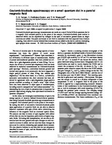
response signals typical in civil structures. Finally, the paper presents a set of field validation tests conducted on the Voigt Bridge, located on the campus of the University of California, San Diego (UCSD). WIRELESS SENSING SYSTEM ARCHITECTURAL DESIGN To offer flexible deployments in civil structural applications, a simple star-topology network is proposed for the wireless structural monitoring system described herein. The system includes one wireless network server and multiple wireless sensing units. Each wireless sensing unit may collect data from multiple sensors, including accelerometers, velocity meters, and strain gages, among others. Incorporated with embedded microcontrollers, the wireless sensing units are endowed with the computational resources that allow them to process their sensor data. The units can also wirelessly communicate sensor data or computation results to the network server. Fig. 1 shows the overall hardware design of the wireless sensing unit. The wireless sensing unit consists of three functional modules: sensor signal digitizer, computational core, and wireless communication module (Fig. 1). The sensor signal digitization module converts analog sensor signals into digital formats which are then transferred to the computational core through a high-speed Serial Peripheral Interface (SPI) port. The computational core then buffers the sensor data in its local memory or processes the data with embedded engineering analytical routines. Through a Universal Asynchronous Receiver and Transmitter (UART) interface, the computational core is able to communicate
The Proceeding of 4th China-Japan-US Symposium on Structural Control and Monitoring Oct.16-17, 2006
3
WIRELESS SENSING UNIT Sensor Signal Conditioning
Computational Core 128kB External SRAM CY62128B
Amplification, Filtering, and Voltage-offsetting Sensor Signal Digitization Structural Sensors
Parallel Port 8-bit Microcontroller ATmega128
SPI Port
4-channel 16-bit Analog-to-Digital Converter ADS8341
UART Port
Wireless Communication Wireless Transceiver : 20kbps 2.4GHz 24XStream, or 40kbps 900MHz 9XCite
Fig. 1. Functional diagram detailing the hardware design of the wireless sensing unit.
with a wireless transceiver, which enables the wireless sensing unit to exchange data with the network server. The functional modules are integrated using a compact two-layer printed circuit board (PCB) as shown in Fig. 2a. All of the hardware components, including batteries, are packaged within a weatherproof plastic container, which has a dimension of 10.2 × 6.5 × 4.0 cm3. As shown in Fig. 1, the structural sensor signal may optionally be amplified and filtered by a sensor signal conditioning module before the signal is fed into the wireless sensing units. The key components and the characteristics of the wireless sensing unit design, as well as the design of the offboard signal conditioning module are described briefly below. Sensing signal digitization module The main component of the sensor signal digitization module is a 4-channel 16-bit analog-to-digital (A/D) converter (Texas Instruments ADS8341). Each wireless sensing
unit can accommodate signals from a heterogeneous set of structural sensors, as long as their outputs are analog voltages from 0 to 5V. The 16-bit A/D resolution is sufficient for most structural monitoring studies. The highest sampling rate supported by this A/D converter is 100 kHz, which is much higher than the sampling frequencies typically employed when monitoring civil structures. Computational core The computational core of the wireless unit is responsible for executing embedded software instructions for engineering analyses. A low-cost 8-bit microcontroller (Atmel ATmega128) is selected as the principle component of the computational core. The key criterion for this selection is to balance the power consumption and cost of the microcontroller versus the computation power needed by software applications. Running at 8MHz, the ATmega128 consumes about 15mA when it is active. The microcontroller Sensor Signal Input
ATmega128 Microcontroller
Conditioned Output Signal
Octal D-type Latch AHC573
Connector to Wireless Transceiver Sensor Connector
SRAM CY62128B
A/D Converter ADS8341
Switch for Selecting Amplification Factor
(a) Wireless sensing unit (9.7 × 5.8 cm2) board.
Operational Amplifier LMC6484
(b) Sensor signal conditioning module (5.0 × 6.5 cm2).
Fig. 2. Photographs of the Printed Circuits Boards.
4
The Proceeding of 4th China-Japan-US Symposium on Structural Control and Monitoring Oct.16-17, 2006
also contains 4kB static random access memory (SRAM) for storing stack and heap variables. The 4kB SRAM is often insufficient for the execution of embedded data interrogation algorithms. To address this issue, an external 128kB memory chip (Cypress CY62128B) is also incorporated within the wireless sensing unit design. Wireless communication module The wireless sensing unit is designed to be operable with two different wireless transceivers: 900MHz MaxStream 9XCite and 2.4GHz MaxStream 24XStream. This unique design feature is intended to allow users to employ the legal open-use frequency band in their regions. Pin-to-pin compatibility between these two wireless transceivers makes it possible for the two modules to share the same hardware connections on the PCB of the wireless sensing unit. Table 1 summarizes the key performance parameters of the two wireless transceivers. As shown in the table, the data transfer rate of the 9XCite is twice as fast as the data rate of the 24XStream; however, the 24XStream provides a longer communication range but consumes much more battery power. Signal conditioning module For field applications, a wireless monitoring system must be able to record both ambient and forced structural vibrations. Most ambient vibrations in civil structures are
characterized by low-amplitude accelerations. Recording these low-amplitude signals can be challenging because the A/D converter is vulnerable to electrical noise in the circuit. A signal conditioning module is designed to amplify signals, filter out noise, and shift the range of sensor signals. The filtering circuit consists of a high-pass resistor-capacitor (RC) filter with a cutoff frequency of 0.02 Hz and a low-pass fourth-order Bessel filter with a cutoff frequency of 25 Hz. The linear-phase shift property of the Bessel filter ensures a constant time delay for signals in the pass band, thus maintaining the signal waveform in the time domain. Fig. 2(b) shows the complete signal conditioning circuit modules that support the filtering, offsetting, and amplification of sensor signals. FIELD VALIDATION TESTS AT VOIGT BRIDGE Laboratory and field validation tests have been previously conducted to verify the performance of the wireless structural monitoring system (Lu et al. 2006, Lynch et al. 2005, Lynch et al. 2006). Field tests are particularly helpful in assessing the limitations of the system, and providing valuable experience that can lead to further improvements in the system hardware and software design. The following sections present an overview of the validation tests conducted on the Voigt Bridge located on the
Table 1. Key performance parameters of the wireless transceivers*. Specification Operating Frequency Data Transfer Rate Communication Range Supply Voltage Power Consumption *
9XCite ISM 902-928 MHz 38.4 kbps Up to 90m indoor, 300m outdoor 2.85VDC to 5.50VDC 55mA transmitting, 35mA receiving, 20µA standby
For details about the transceivers, see http://www.maxstream.net.
24XStream ISM 2.4000 – 2.4835 GHz 19.2 kbps Up to 180m indoor, 5km outdoor 5VDC (±0.25V) 150mA transmitting, 80mA receiving, 26µA standby
The Proceeding of 4th China-Japan-US Symposium on Structural Control and Monitoring Oct.16-17, 2006
UCSD campus. Up to 20 wireless sensing units are deployed in the field to simultaneously collect the ambient and forced vibration response of the bridge for operating deflection shape analysis.
for structural health monitoring research, a sophisticated cable-based structural monitoring system has been installed in the northern-most cells of the Voigt Bridge (Fraser et al. 2006). The cable-based system includes accelerometers, strain gages, thermocouples, and humidity sensors. For the purpose of validating the proposed wireless structural monitoring system, thirteen accelerometers interfaced to wireless sensing units are installed within the two middle spans of the bridge to measure vertical vibrations. One wireless sensing unit (associated with one signal conditioning module and one accelerometer) is placed immediately below the accelerometer associated with the permanent wired monitoring system. While the wired accelerometers are mounted to the cell walls, wireless accelerometers are simply mounted on the floor of the girder cells to expedite the installation process. The installation and calibration of the wireless monitoring system, including the placement of the 13 wireless sensors, takes about an hour. The Maxstream 9XCite wireless transceiver operating at 900MHz (allowed by US government regulations) is integrated with
Voigt Bridge Voigt Bridge is a concrete box girder highway bridge that carries traffic over Interstate 5. The two-lane bridge is about 89.4m long and consists of four spans (Fig. 3). The bridge deck has a skew angle of about 32º, with the concrete box-girder supported by three single-column bents. Over each bent, a lateral diaphragm with a thickness of about 1.8m stiffens the girder. The thickness of the concrete lateral diaphragms poses substantial challenges for the transmission of wireless signals within the box girder. Longitudinally, the box girder is partitioned into five cells running the length of the bridge (Fig. 3b). Comparison between cabled and wireless sensor data Girder cells along the north side of the bridge are accessible through four manholes on the bridge sidewalk. As a testbed project A
Lateral diaphragm
1
2
3
4
5
6
7
8
9
10
11 12 13
Longitudinal diaphragm
6.1 m
Abut. 1
16.2 m N
Bent 2 A
29.0 m
Wireless network server
Bent 3
29.0 m
Abut. 2
6.1 m
Bent 1
15.2 m
One pair of wireless and wired accelerometers
(a) Plan view of the bridge illustrating sensor locations of wired and wireless monitoring systems. Wired accelerometer
1.8 m
Wireless accelerometer
10.7 m
Section A-A
(b) Elevation view to section A-A.
5
(c) Side view of the bridge over Interstate 5.
Fig. 3. Voigt Bridge on the campus of the University of California, San Diego.
The Proceeding of 4th China-Japan-US Symposium on Structural Control and Monitoring Oct.16-17, 2006
each wireless sensing unit. Two types of accelerometers are associated with each monitoring system. At locations #3, 4, 5, 9, 10, and 11 in Fig. 3a, PCB Piezotronics 3801 accelerometers are used with both the cabled and the wireless systems. At the other seven locations, Crossbow CXL01LF1 accelerometers are used with the cabled system, while Crossbow CXL02LF1Z accelerometers are used with the wireless system. Table 2 summarizes the key parameters of the three types of accelerometers. Signal conditioning modules are used for filtering noise, amplifying and shifting signals for the wireless accelerometers. The signals of the wired accelerometers are directly digitized by a National Instruments PXI-6031E data
acquisition board (Fraser et al. 2006). Sampling frequencies for the cable-based system and the wireless system are 1,000 Hz and 200 Hz, respectively. The bridge is under normal traffic operation during the tests. Fig. 4(a) shows the time history data at locations #6 and #12, collected by the cable-based and wireless monitoring systems when a vehicle passes over the bridge. A close match is observed between the data collected by the two systems. The minor difference between the two data sets can be mainly attributed to two sources: 1) the signal conditioning modules are used in the wireless system but not in the cabled system; 2) the wired and wireless accelerometer locations are not exactly adjacent to each other, as previously described.
Table 2. Parameters for accelerometers used in the cabled and wireless sensing systems.
Maximum Range Sensitivity RMS Resolution (Noise Floor)
PCB3801
CXL01LF1
CXL02LF1Z
±3 g 0.7 V/g 0.5 mg
±1 g 2 V/g 0.5 mg
±2 g 1 V/g 1 mg -3
x 10
Acceleration (g)
Acceleration (g)
-3
5
0 Wired #6 -5
0
2
4
6
8
5
5
x 10
0 Wireless #6 -5
-3
0
5
0
4
6
8
4 Time (s)
6
8
x 10
0 Wired #12
-5
2 -3
x 10
0
2
Wireless #12 4 Time (s)
6
-5
8
0
2
FFT Magnitude
(a) Comparison between wired and wireless time history data. 4 Wired #6 2 0
0
5
10
15
FFT Magnitude
6
Wireless #6 0.5
0
0
5
10
15
4 Wired #12
0.5
2 0
0
5
10 Frequency (Hz)
Wireless #12
15
0
0
5
10
15
Frequency (Hz)
(b) Comparison between FFT to the wired data, as computed offline by a computer, and FFT to the wireless data, as computed online by the wireless sensing units. Fig. 4. Comparison between results from two monitoring systems (Location numbers are as shown in Fig. 3a).
The Proceeding of 4th China-Japan-US Symposium on Structural Control and Monitoring Oct.16-17, 2006
Fig. 4(b) shows the Fourier spectrum results determined from the time history data. The FFT results using the data collected by the cabled system are computed offline, while the FFT results corresponding to the wireless data are computed online in real-time by each wireless sensing unit. After each wireless sensing unit executes its FFT algorithm, the FFT results are wirelessly transmitted to the network server. Strong agreement between the two sets of FFT results validates the computational accuracy of the wireless sensing units. It should be pointed out that because the sampling frequency of the cabled system is five times higher than that of the wireless system, the magnitude of the Fourier spectrum for the cabled system is also about five times higher than those for the wireless system.
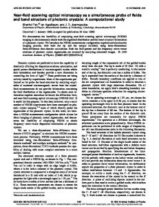
monitoring system is changed to attain a more suitable spatial distribution. Twenty wireless accelerometers and the wireless network server are now mounted to the bridge sidewalks, instead of inside the girder cells (Fig. 5). The communication distance between the server and the farthest-away wireless sensing unit is close to the full length of the bridge. Both vehicle traffic and hammer excitations are employed during the test. Hammer excitation is applied during intervals of no passing vehicles. The operating deflection shape (ODS) analysis presented in this paper is based on the data collected during a hammer excitation test. DIAMOND, a modal analysis software package, is used to extract the operating deflection shapes of the bridge deck (Doebling et al. 1997). Under hammer excitation, the operating deflection shapes at or near a resonant frequency should be dominated by a single mode shape (Richardson 1997). Fig. 6 presents the first four dominant operating deflection shapes of the bridge deck using wireless acceleration data. The ODS #1, #2, and #4 show primarily
Operating deflection shape analysis One attractive feature of the wireless monitoring system is its easy reconfigurability. To determine the operating deflection shapes of the bridge deck, the configuration of the original wireless 1
2
3
4
5
6
7
8
9
10 6.1 m
Abut. 1 Bent 1
16.2 m N
Bent 2
12 13
14
Bent 3
16 17
15
29.0 m
18
19
Wireless network server
Abut. 2
20
29.0 m
6.1 m
11
15.2 m
Wireless accelerometer
Hammer location
Fig. 5. Wireless accelerometer deployment for operating deflection shape analysis. ODS #1, 4.89Hz
ODS #2, 6.23Hz
0.5 0 -0.5 -60
0 -10 -40
-20
0 20 ODS #3, 8.01Hz
40
60
0.5 -0.5 -60
-20
0
0
-10 -40
-20
0
20
40
60
7
-20
0.5 0 -0.5 -60
0 -10 -40
-20
0 20 ODS #4, 11.64Hz
40
60
0.5
0
0 -0.5 -60
-20
-10 -40
-20
0
20
40
Fig. 6. Operating deflection shapes extracted from wireless sensor data.
60
-20
8
The Proceeding of 4th China-Japan-US Symposium on Structural Control and Monitoring Oct.16-17, 2006
flexural bending modes of the bridge deck; a torsional mode is observed in ODS #3.
obtained using the acceleration data collected simultaneously by 20 wireless sensing units.
SUMMARY AND DISCUSSION
ACKOWLEDGEMENT
A wireless structural health monitoring system specifically designed for expedient onsite deployment to civil structures is presented in this paper. Robust software and hardware designs enable low-cost and reliable data collection and interrogation from a network of autonomously functioning wireless sensing units. The paper presented findings from a field validation test conducted at the Voigt Bridge located on the UCSD campus. Strong agreement is observed between the data collected by the wireless system and the data collected by a baseline cable-based monitoring system. Operating deflection shapes of the bridge deck are successfully
This research is partially funded by the National Science Foundation under grants CMS-9988909 (Stanford University), CMS0528867 (University of Michigan), ITR0205720 (UCSD), and the Office of Naval Research Young Investigator Program awarded to Prof. Lynch at the University of Michigan. The authors wish to thank following three fellowship programs: the Office of Technology Licensing Stanford Graduate Fellowship, the Rackham Grant and Fellowship Program at the University of Michigan, and the fellowship provided by California Institute for Telecommunications and Information Technology.
References Celebi, M., 2002. Seismic Instrumentation of Buildings (with Emphasis on Federal Buildings). Report No. 07460-68170 United States Geological Survey (USGS), Menlo Park, CA, USA. Doebling, S.W., Farrar, C.R., Cornwell, P.J., 1997. DIAMOND: A Graphical User Interface Toolbox for Comparative Modal Analysis and Damage Identification. Proc. of 6th International Conference on Recent Advances in Structural Dynamics, 399-412. Southampton, UK. Farrar, C.R., Sohn, H., Hemez, F.M., Anderson, M.C., Bement, M.T., Cornwell, P.J., Doebling, S.W., Schultze, J.F., Lieven, N., Robertson, A.N, 2003. Damage Prognosis: Current Status and Future Needs. Report LA-14051-MS, Los Alamos National Laboratory, NM, USA. Fraser, M., Elgamal, A., Conte, J.P., 2006. UCSD Powell Laboratory Smart Bridge Testbed. Report No. SSRP 06/06, Department of Structural Engineering, University of California, San Diego, La Jolla, CA, USA. Lu, K.-C., Wang, Y., Lynch, J.P., Loh, C.-H., Chen, Y.-J., Lin, P.-Y., Lee, Z.-K., 2006. Ambient Vibration Study of the Gi-Lu Cable-Stay Bridge: Application of Wireless Sensing Units. Proc. of SPIE 13th Annual Symposium on Smart Structural and Materials. San Diego, CA, USA.
Lynch, J.P., Loh, K., 2005. A Summary Review of Wireless Sensors and Sensor Networks for Structural Health Monitoring. Shock and Vibration Digest, 38:91-128. Lynch, J.P., Wang, Y., Law, K.H., Yi, J.H., Lee, C.G., Yun, C.B., 2005. Validation of Large-Scale Wireless Structural Monitoring System on the Geumdang Bridge. Proc. of 9th International Conference on Structural Safety and Reliability. Rome, Italy. Lynch, J.P., Wang, Y., Lu, K.-C., Hou, T.-C., Loh, C.-H., 2006. Post-seismic Damage Assessment of Steel Structures Instrumented with Self-interrogating Wireless Sensors. Proc. of 8th National Conference on Earthquake Engineering. San Francisco, CA, USA. Richardson, M. H., 1997. Is It A Mode Shape Or An Operating Deflection Shape?. Sound and Vibration Magazine, 31:54-61. Straser, E.G., Kiremidjian, A.S., 1998. A Modular, Wireless Damage Monitoring System for Structures. Report No. 128, John A. Blume Earthquake Eng. Ctr., Stanford Univ., Stanford, CA, USA. Wang, Y., Lynch, J.P., Law, K.H., 2006. A Wireless Structural Health Monitoring System with Multithreaded Sensing Devices: Design and Validation. Structure and Infrastructure Engineering, in press.