in the case of large space such as sports stadiums, it is dif- ficult to set many calibrating points of which the positions are precisely measured throughout the ...
View Interpolation of Multiple Cameras Based on Projective Geometry Hideo Saito1,2 ,
Makoto Kimura1,
Satoshi Yaguchi1,
Naho Inamoto1
1. Department of Information and Computer Science, Keio University 3-14-1 Hiyoshi Kohoku-ku, Yokohama 223-8522, Japan {saito,kimura,yagu,nahotty}@ozawa.ics.keio.ac.jp
2. PRESTO, Japan Science and Technology Corporation (JST)
Abstract We will show methods for interpolation of viewpoint from multiple cameras based on projective geometry. Projective relationship of multiple cameras can be obtained from weak calibration information, that can easily be corrected from the multiple view images. Such projective geometry provides sufficient information to reconstruct the 3D shape of the object with scale and projective transformation ambiguity. Since such ambiguity does not affect to 2D correspondence relationship between the multiple images, we can generate new view point images from multiple cameras by interpolating viewpoint according to the 2D correspondence relationship. We will show following approaches for interpolating the view point of multiple cameras : 1) View interpolation from 3D shape reconstruction with projective ambiguity in Projective Grid Space (PGS), 2) View interpolation of actual soccer scene taken with multiple cameras based on projective geometry.
1. Introduction The new view synthesis from images is recently studied for enhancing the visual entertaining effect of the movie. One method for enhancing the visual effect is virtual movement of viewpoint so that the audience can virtually feel existence in the object scene. The recent applications of such effect are known as ”Matrix” of Hollywood movie, EyeVision system in the SuperBowl 2001 broadcast by CBS, etc. Virtualized Reality (TM) [3, 8] is one of the frontier project that realizes such virtual viewpoint movement for dynamic scene by the use of computer vision technology. Although the “Matrix” and “EyeVision” are just a switching effect of multiple camera real images, the computer vision-based technology can flexibly generate arbitrary viewpoint images for the virtual viewpoint movement effect.
We aim to apply the virtualized reality technology to actual sports events, etc [4, 5, 6, 9]. The new view images are generated by rendering pixel values of input images in accordance with the geometry of the new view and the 3D structure model of the scene, which is reconstructed from multiple-view images. The 3D shape reconstruction from multiple view generally requires strong camera calibration that is used for relating the camera geometry to the object shape space geometry. For strongly calibrating cameras, 3D position in Euclidean space of several points and 2D position on each view images of those points must be measured precisely. For this reason, when there are many cameras, much effort is needed to calibrate every camera. Especially, in the case of large space such as sports stadiums, it is difficult to set many calibrating points of which the positions are precisely measured throughout the large area. On the other hand, projective geometry between cameras that is represented by fundamental matrix can be estimated from 2D point correspondence between the cameras. Such projective geometry-based calibration is called as weak calibration. Since 3D positions of the points are not required for estimating fundamental matrix, there is no need for locating artificial markers at known 3D position, but detecting natural feature points is enough for weak calibration. This implies that much labor can be reduced if weak calibration is sufficient for view generation from multiple cameras. Such projective geometry provides sufficient information to reconstruct the 3D shape of the object with scale and projective transformation ambiguity. Since such ambiguity does not affect to 2D correspondence relationship between the multiple images, we can generate new view point images from multiple cameras by the projective geometry. In this paper, we will show following approaches for generating new views by interpolating the view point [1, 7] of multiple cameras: 1) View interpolation from 3D shape reconstruction with projective ambiguity in Projective Grid Space (PGS), 2) View interpolation of actual soccer scene taken with multiple cameras based on projective geometry.
Figure 1. Euclidean grid and projective grid. Figure 2. Definition of projective grid.
2. View Interpolation in Projective Grid Space
Projective Grid Space
2.1. Projective Grid Space We have already proposed a new framework for shape reconstruction from uncalibrated multiple cameras in the “Projective Grid Space (PGS)” [5], in which the coordinate is defined by epipolar geometry between cameras. The general euclidean reconstruction is performed in the 3D space that is defined independently from camera geometry as shown in Figure 1 (a). For relating the camera geometry with the 3D space, we need a map of 3D position in 3D space and 2D position on the image, which is generally collected by using artificial marker with known 3D position. Such procedure is strong calibration. On the other hand, projective reconstruction can be performed in the 3D space that is defined dependently on the camera geometry as shown in Figure 1 (b). In this case, we need only camera to camera relationship in 2D-2D correspondence between different cameras by weak calibration, because the 3D space is represented by the camera geometry. Figure 2 shows the definition of the projective grid space (PGS) framework. In this framework, first we select two cameras for defining the projective grid. Every grid point in the objective space is represented by (p, q, r). The (p, q) is defined by the projected position of the grid point on basis view 1. The r is the horizontal or vertical coordinate of the projected position of the grid point on basis view 2. In such a way, position of every grid can be represented via the projected position of two basis views.
2.2. Model Reconstruction For reconstructing the 3D shape of the object in this projective grid space, we can use shape from silhouette method, for example. For reconstructing the shape via shape from silhouette method, we consider volumetric voxel space of which position is represented by (p, q, r). Then every voxel
P
R Q
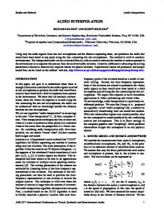
A(p , q , r) R a2(r , s)
P F2i
a1(p , q) Q
F1i BasisView1
BasisView2
OtherView i
Figure 3. Projection of a point in PGS onto an arbitrary image.
position is projected onto all the camera images for checking if the voxel is inside the object shape of the outside. We can project onto every camera by using fundamental matrices between the camera and the two basis cameras. A grid point A(p, q, r) is projected onto a1 (p, q) and a2 (s, r) in the basis view 1 and the basis view 2, respectively. The point a1 is projected as the epipolar line l on the second basis view. The point a2 on the projected line (figure 2), is expressed as l = F 21 [p, q, 1]T
(1)
where F 21 represents the fundamental matrix between the first and second images. The projected point in ith arbitrary real image is determined two fundamental matrices, F i1 , F i2 between two basis images and ith image. Since A(p, q, r) is projected onto a1 (p, q) in the first basis image, the projected point in the ith image must be on the epipolar line l1 of a1 (p, q), which is derived by the F i1 as
Figure 4. Synthesis of desired view from neighboring three cameras.
l1 = F i1 [p, q, 1]T
(2)
In the same way, the projected point in the ith image must be on the epipolar line l2 of a2 (r, s) in the basis image, which is derived by the F i2 as l2 = F i2 [r, s, 1]T
(3)
The intersection point between the epipolar line l1 and l2 is the projected point A(p, q, r) onto the ith image (figure3). In this way, every projective grid point is projected onto every image, where the relationship can be represented by only the fundamental matrices between the image and two basis images. Outline of the process for reconstructing 3D shape model is as follows. First of all, two cameras are selected from as basis cameras, and then coordinate of PGS is determined. Every voxel in the coordinate is projected onto each silhouette image with proposed scheme as shown in figure 3. The voxel that is projected onto the object silhouette for all images is decided as existent voxel, while others are nonexistent. Thus the volume of the object can be determined in the voxel represented in PGS. For such 3D shape reconstruction in the projective grid space, we need fundamental matrix between the selected basis views, and fundamental matrices between each basis views and the other cameras, that means 1 + (N − 2) × 2 fundamental matrices are required in total.
2.3 Arbitrary View Synthesis Arbitrary view image is synthesized as intermediate images of selected neighboring two or three reference real images. If two reference images are selected, virtual viewpoint can be taken on the line between two reference real
Figure 5. Synthesized intermediate view images among three images.
viewpoints. In case of three reference images, virtual viewpoint can be taken inside of the triangle that is formed by the three real viewpoints. Therefore, if a number of cameras are mounted on a dome around the target space and each cameras formed triangle effectively, virtual viewpoint can be moved freely on the surface of the dome. For synthesizing arbitrary view image, intermediate image are synthesized by interpolating two or three reference images. The interpolation is based on the related concepts of view interpolation [1]. At reference views, depth in PGS are rendered at the reference views with z-buffer algorithm. To apply the z-buffer algorithm to render the 3D model at the reference views, the surface of 3D model that reflect on the input views is decided. In the z-buffer of each pixel, the distance between the viewpoint and the closest surface point is stored, and the stored distances. Then these rendered depth images generate the correspondence maps between the reference images. For the correspondence points between the reference images, the following equations are applied to the interpolation: P
= w1 P i + w2 P j + w3 P k
(4)
I(P ) = w1 Ii (P i ) + w2 Ij (P j ) + w3 Ik (P k ) (5) Pi , Pj and Pk are the position of the corresponding points in the three reference images (Figure4), Ii (Pi ) , Ij (Pj ) and Ik (Pk ) are the colors of the corresponding points, and P and I(P ) are the interpolated position and color. The interpolation weighting factors are represented by w1 , w2 and
w3 (w1 + w2 + w3 = 1, 0 ≤ w1 , w2 , w3 ≤ 1). Changing the weighting ratio, virtual viewpoint can move inside of the triangle. However, there is the case that some points in one image cannot be seen in another image. In this case, the position on the interpolating image of such point is calculated by equation 4, and the color is decided on the value of visible point. Therefore, even if certain region is occluded on the one image, the region can be synthesized on the novel image, as long as the region is not occluded on the other images. Figure 5 shows synthesized intermediate viewpoint images of a scene in which two men are doing lifting. Three images at the vertices of the triangle are the selected reference images of the same frame. Arbitrary view images are synthesized from those images by changing the weighting ratio. The images on the line are interpolated from two reference images of both ends, and center of the image is interpolated from three reference images.
3. View interpolation of actual soccer scene The key idea for interpolating viewpoint of actual soccer scene is to segment the object regions according to the property of the soccer scene, and apply proper projective transforms for generating the intermediate views. This enables us to successfully generate natural intermediate view videos from actual soccer scenes captured at the stadium[2].
3.1. Algorithm In this method, object scene is divided into three regions. Employing a method appropriate for each region generates intermediate view images of each region. Figure 6 shows how to divide an object scene. First, it’s divided into dynamic region, in which shape or position changes with time, and static region. As dealing with soccer scene, the former corresponds to players and ball and the latter to ground, goal, and background. Next the latter is also divided into two regions by shape. One is ground and goal, which we can approximate their shape to set of planes, and the other is background, which we can approximate its shape to plane existing at infinity. Finally the object scene is divided into three regions as players/ball, ground/goal, and background. Intermediate view images are respectively generated in every three region and last of all synthesizing them completes images of the whole object. Following is the detailed explanation of each region. Players and ball As one scene usually contains several players and a ball, we deal with them separately. First, all dynamic regions are extracted by subtracting background.
Figure 6. Object scene Considering not only intensity but also color vector consisted of RGB extracts them more accurately. After each silhouette is generated for segmentation of every player and ball, each segmented silhouette of players is corresponded between different view images by using homography of the ground as shown in figure 7. This is based on the fact that players are standing on the ground and feet of the players can be related by the homography of the ground. Next each pair of silhouette is extracted for obtaining pixel-wise correspondence inside the silhouette region. Epipolar lines are drawn between the different view images, view 1 and view 2, using fundamental matrix, as shown in figure 8. On each epipolar line, the intersections with boundary of silhouette, such as a1 and a2 , b1 and b2 in figure 8, are corresponded first. The pixels inside of the silhouette are corresponded by linear interpolation of the intersection points. Thus drawing epipolar lines on the silhouette can obtain dense correspondence of the whole silhouette. The correspondence transfers the pixel values from the source images of view 1 and view 2 to the virtual view images by linear interpolation of the displacement of the pixel positions. In this case, the virtual viewpoints can be placed only between existing viewpoints, but it’s promising that realistic images are generated within that area. The synthesized view location is given by ´ = (1 − α)p1 + αp2 p
(6)
where p1 , p2 are coordinates of matching points on image I1 , I2 , and also α is weight to existing viewpoint. Transfer of all correspondences generates warped image. Here two
Figure 7. Silhouette correspondence
Figure 9. Intermediate view images of ground and goal
Figure 8. Transfer of correspondence
Figure 10. Synthesized mosaic image
transfers are required, that is from view 1 and from view 2. The reason is because correspondence is approximately given between two view images whose texture is different. Therefore two different warped images are generated and blending them completes intermediate view images. If a pixel has color on both images, average of them is rendered, else if either one, the color is rendered. For all of the extracted players and ball, the pixel-wise correspondence is established for rendering intermediate views. Finally they are synthesized in distant order from viewpoint. In this way, intermediate view images for the dynamic regions are completed.
Background As background can be considered as one plane existing at infinity, we can employ image mosaicking technique for generating a panoramic image of two input view images of the background. Intermediate view images of this region are extracted from the panoramic image. First, two coordinate systems of two views are integrated by using homography H21 which represents homography matrix of the background. Next two backgrounds are connected and colors of junction are smoothed. Partial area that is necessary for each intermediate view image is cut out from the synthesized mosaic image. Finally transformation ´ completes inof coordinate using following homography H termediate view images of the background region.
Ground and goal In an object scene, ground and soccer goal can be considered as one plane, and set of planes, respectively. We can employ homography of the plane to obtain correspondence for generating the intermediate view images. Following equation gives pixel-wise correspondence for each plane between two views. p2 ∼ = Hp1
(7)
where H is homography matrix of the plane, and p1 , p2 are homogeneous coordinates on image I1 , I2 . The homography matrices of the planes that represent the ground and soccer goal provide dense correspondence inside the regions. Next as same as players and ball, corresponding points are transferred by linear interpolation and the destination images are rendered from the original images. Figure 9 presents examples of generated intermediate views for the ground and goal regions, where the virtual viewpoint is placed at the center of pair of existing viewpoints.
´ = (1 − α)E + αH21 −1 H
(8)
where α is weight and E is unit vector. Figure 10 presents an example of synthesized mosaic images.
3.2. Experimental results We applied this method to actual soccer scenes taken by multiple video cameras at the stadium. Figure 11 illustrates
Figure 11. Multiple camera system
Figure 12. Generated intermediate views the multiple camera system. Each of four cameras is placed on one side to take penalty area at the center. All input images are 720 × 480 pixels, RGB 24 bits color images. In this experiment, we manually selected about 20 corresponding feature points between input images. Figure 12 presents some results of generated intermediate views. From (a) to (h), with change of viewpoint, position of players and location of background are gradually changing. Three images on the bottom especially present closed up views of dynamic regions of (c),(e),(g). Comparing with input images, we can successfully obtain realistic images without distortion. While in this method each region, that is players/ball or ground/goal or background, is rendered separately, synthesized images look so natural that we can’t find junctions. Full color versions of these images and generated intermediate view videos can be found at http://www.ozawa.ics.keio.ac.jp/˜nahotty/research.html.
4. Conclusion This paper has presented two methods to generate intermediate view images from multiple cameras based on projective geometry. In many cases, it is difficult to strongly calibrate the cameras for estimating camera parameters. Especially in a sports stadium, it is almost impossible. For such cases, the presented methods are effective for intermediate view generation, because they don’t need camera parameters, but only needs fundamental matrices between the cameras, which we can easily obtain by correspondence of natural feature points between images.
References [1] T.Beier, S.Neely : ”Feature-Based Image Metamorphosis”,Proc. of SIGGRAPH ’92, pp.35-42, 1992. [2] Naho Inamoto, Hideo Saito, “Fly Through View Video Generation of Soccer Scene”, First International Workshop on Entertainment Computing(IWEC2002), 2002 (submitted). [3] T.Kanade, P.W.Rander, S.Vedula, H.Saito, “Virtulized Reality:Digitizing a 3D Time-Valying Event As Is and in Real Time”, International Symposium on Mixed Reality(ISMR99), pp41-57, Yokohama, Japan, March 1999. [4] I.Kitahara, H.Saito, Y.Ohta, S.Akimichi, T.Ono, T.Kanade, “Large Scale Virtualized Reality”, Technical Sketches, IEEE CVPR2001, 2001. [5] H.Saito,T.Kanade, “Shape Reconstruction in Projective Grid Space from Large Number of Images”, IEEE Proc. Computer Vision and Pattern Recognition, Vol.2, pp.49-54, 1999. [6] H.Saito, S.Baba, M.Kimura, S.Vedula, T.Kanade, “Apperance-Baced Virtual View Generation of TemporallyVarying Events from Multi-Camera Images in 3D Room”,Second International Conference on 3-D Digital Imaging and Modeling (3DIM99), pp.516-525, 1999. [7] S.M.Seitz, and C.R.Dyer, “View Morphing”,proc. of SIGGRAPH ’96, pp.21-30, 1996. [8] S.Vedula, P.W.Rander, H.Saito, T.Kanade, “Modeling, Combining, and Rendering Dynamic Real-World Events From Image Sequences”, Proc. 4th Conf. Virtual Systems and Multimedia, Vol.1, pp.326-322, 1998. [9] S. Yaguchi, H.Saito, “Arbitrary View Image Generation from Multiple Silhouette Images in Projective Grid Space”, Proceedings of SPIE Vol.4309, pp.294-304, January 2001.