View Synthesis using Convex and Visual Hulls ... This results in a simpler method of using the visual hull ([9]) for view ..... [10] D. Snow, P. Viola, and R. Zabih.
View Synthesis using Convex and Visual Hulls Y. Wexler R. Chellappa Center for Automation Research University of Maryland College Park Abstract
This paper discusses two efficient methods for image based rendering. Both algorithms approximate the world object. One uses the convex hull and the other uses the visual hull. We show that the overhead of using the latter is not always justified and in some cases, might even hurt. We demonstrate the method on real images from a studio-like setting in which many cameras are used, after a simple calibration procedure. The novelties of this paper include showing that projective calibration suffices for this computation and providing simpler formulation that is base only on image measurements.
1 Introduction This paper considers the problem of image-based rendering given many images around an object. Given this collection of views we want to generate a new view of the scene from some given camera. For the application of view synthesis, the goal is to quickly generate a new image for each video frame. In this case, the construction of a full geometrical model is not needed. When the object in the scene moves, each frame may present a substantially different object. Model construction is a complex operation and updating it even more so. In recent work, [12] showed that this can be done without using voxels or optical flow. This results in a simpler method of using the visual hull ([9]) for view synthesis. In this paper we show that strict Euclidean calibration is not needed and so the same geometrical computation can be done when only projective calibration of the cameras is performed. We discuss a special case of the visual hull – the convex hull – whose special form leads to simpler algorithms that may suffice, and, in some cases might be preferred.
1.1 Previous Work There is a an abundance of work on scene modeling from multiple views. In [1] optical flow is used to synthesize novel views from two similar views. In [4] several views are used to texture a 3D graphical model, resulting in a realistic looking scene. This requires a considerable amount of manual work and thus is not applicable to a constantly changing scene. The multi-camera studio setting in [7], in which many synchronized cameras are used to capture a scene resembles our setting. Two methods are used in [7]. One relies on a pairwise stereo algorithm in which depth maps from several nearby camera pairs are combined. The resulting surfaces are then combined and textured in space. Shortcomings
153
O’
O
(a)
O’
O
O’
O
(b)
(c)
O’
O
(d)
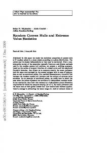
Figure 1: Convex and visual hulls of a simple scene. 1(a) Two bounding planes in each image define the convex hull. 1(b) The resulting convex hull is used as an approximation to the shape. 1(c) Any number of bounding planes in each image define the visual hull 1(d) The resulting visual hull. As can be seen, there are ghost artifacts in the shape.
(a)
(b)
(c)
(d)
(e)
(f)
(g)
(h)
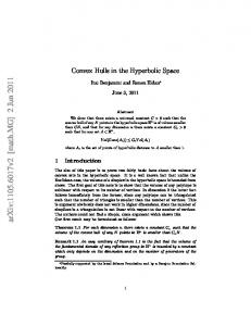
Figure 2: Image warping process: 2(a) Top view of a scene object. 2(b) Silhouette is extracted in two views. 2(c) The intersection of the silhouettes defines the approximation of the object. 2(d) For each pixel in a new view, a ray is cast and intersected with the convex hull. 2(e) Backward-facing planes are eliminated. 2(f) Only one intersection point satisfies all the constraints. 2(g) This point is projected onto the source image. 2(h) The pixel is copied onto the target image.
154
(a) Image and silhouette
(b) Boundary
(c) 2D Convex hull
(d) 2D Hull
Visual
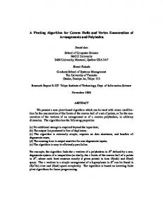
Figure 3: Representing the silhouettes: (a) One of the input images and the silhouette which is extracted automatically. (b) the boundary of the silhouette. (c) The convex hull of the silhouette is used to define the convex hull of the 3D object. (d) Approximation of the silhouette with up to 100 line segments. The collection of segments defined the visual hull of the 3D object. As can be seen, this optional step changes the silhouette very little.
of this approach include the reliance on texture for establishing correspondence, low accuracy resulting from the small baseline between the cameras and a heavy computational load. [9] defines the Visual Hull which is used in work as in [8] where a discrete computation of the visual hull shows the usefulness of such a representation for multi-view synthesis. The use of voxels simplifies shape representation, which is otherwise hard. Its drawback is the added quantization error degrading the reconstruction. In order to overcome this, papers such as [3, 5] and [10], use other means to “smooth” the voxels. Also, the 3D volumetric representation limits the usability as it allows only small number of voxels to be used due to significant memory and computational requirements. [11] uses an Octree representation in order to alleviate this. Note that the need to position the 3D grid itself requires Euclidean calibration. This paper is organized as follows. The different representations and their construction is discussed in section 2 followed by a detailed description of the algorithms in section 3. Section 4 compares the two methods.
2 Model Construction We assume that many projectively calibrated views of the world are available and that automatic extraction of the silhouettes of the objects is done (using [6]) . The goal is to use this information to create new views. Creating the new views requires some estimation of the shape using which, we can warp the existing images to create a new view. For this purpose, the representation of the shape needs to be able to answer one type
155
of query: What is the intersection of any given ray with the shape? In this paper we consider two shape representations. The convex hull and the visual hull. As seen in figure 1, both representations produce a polyhedral model. The convex hull results a convex polyhedron and the visual hull may result a more complex shape, possibly with several connected components. Both shapes are upper bounds on the actual object and the visual hull provides a tighter bound. Once we have the parameters of the new image we want to synthesize (center of projection, orientation, size, etc.) we can simulate the process of taking an image. We shoot (lift) a ray through each pixel as shown in figure 2. The closest intersection of this ray with the object is the world point whose color would be recorded in this pixel position. Since there are many views of the object, a good estimate of this color can be given by inspecting the projection of this point onto the given images.
2.1 Convex Hull The convex hull of a shape is defined as the intersection of all half-spaces containing it. Given a finite collection of views, can define a finite set of such half-spaces whose intersection is guaranteed, by the definition of intersection, to contain the convex hull. As we only have a finite set of views, we term it the apparent convex hull. Given an image of the object, and the silhouette in that image, each line that is tangent to the silhouette defines a world plane that is tangent to the object (see figure 4(b)). Let be a line in some image, whose camera matrix is . The 4-vector is a world plane containing all the world points that project onto . This plane divides the world points into two groups, those on the plane ( ) and those not on it ). Since is defined with respect to a given view, we can also distinguish the ( two sides of it inside the viewing frustum and so can define a half space that contains all the world points whose projection onto the image lies on one side of . can be scaled so that a world point lies “outside” of the shape if . If is tangent to the image of the object then is tangent to the object. Therefore the intersection of all the half spaces that can be recovered from the given input images define the apparent convex hull of the object. The intersection of any world ray with the convex hull is the intersection with one of the planes that defines it. The convex hull representation of the object is then a collection of planes , each of them is accompanied by an image line with its corresponding camera matrix.
� � � � �
�
�
�
�
� ��� �����������������
� � ���
�#"� $� �
% ' ) '1+ -2/
��� �� �
� � � � �!
%&�('*),'.+ -0/
2.2 Visual Hull One of the definitions of the visual hull is as the collection of world points that project inside all the silhouettes in all possible images. Using this definition, given a finite collection of images, any given world point will belong to the visual hull only if its projection onto all the images lies inside the silhouette. Just as the convex hull can be represented as a collection of lines in the given images, the visual hull can be represented by line segments where each segment is locally tangent to the silhouette (see figure 3). This lets us treat the visual hull as an extension of the previous case, or vice versa, treats the convex hull as a special case of the visual hull. The usefulness of this representation is twofold. First, we reduce the amount of data that
156
needs to be stored as there are fewer pixels on the boundary than inside the silhouette. And second, we can use less segments for the description with hardly degrading the shape. While a line segment does not induce a volume in space that we can later intersect, it does answer the only question that we need in order to do view synthesis. Let be some ray in the world. If the projection of on the image intersects the line segment ��� (see figure 4) then the ray might intersect the visual hull at the point that is the intersection of and the plane defined by the line containing the segment. The true intersection point has to lie inside the silhouette and so information from other images can refine this computation. The use of line segments instead of (infinite) lines makes the visual hull more complex and more computationally intensive. The gain is that it provides a better (i.e. tighter) representation of the shape. In section 4 we show that this added complexity is not necessarily needed for view synthesis of simple objects. The visual hull representation of the object is then the collection of line segments in each image ���� �� � accompanied by their corresponding camera matrices.
% ' � �' ) '.+ -0/
3 Algorithm Descriptions In this section we describe the algorithms we use to generate new views using the convex and the visual hulls. The special form of the convex hull leads to a simpler algorithm that is substantially different. The conceptual algorithm in both cases is similar: we lift a ray through each pixel and then find the intersection of the ray with the shape. The world point that is the intersection is projected onto a source image and thus induces a warping function which generates the target image. The difference between the two methods is the actual intersection with the shape. Also, special geometrical properties are used in each case to bypass some of the work. There are three important observations here: 1. Both the convex and visual hulls result in polyhedral models and so the mapping between source image and the target image is done via 2D planar homographies. The task of the algorithms is to find the correct homography for each pixel. 2. The above definition does not require a Euclidean frame of reference, as the only relationship is that of incidence (and not, say, perpendicularity) 3. As both representations use tangent planes, a 3D ray intersects a facet only if its projection intersects the line that defined the facet. This enables us to do all the computations in (2D) image space. The collection of rays given by the new view needs to be intersected with the representation of the object. We describe the two different methods below. The intersection of the rays with the object gives the (projective) depth which can be used for view synthesis.
3.1 Rendering via Convex Hull
�
"�
��
Let be the new view. Let �� ���� � �� be the center of projection of the new camera. Rays that emanate from might intersect the convex hull at two points, front and back.
�
157
Regardless of the distance to these points, we can eliminate one of them as has to be outside of the half-space defined by the plane that it is viewing. This can be seen as projective backface culling.
l e ag
m tI ge ar
T
Π
H
O Source Image
(b) An image line � defines the world plane � through the origin of the camera. � is tangent to the object if � is tangent to the silhouette. The crucial observation here is that a 3D ray � intersects � only if its projection intersects � . This lets us use � implicitly.
(a) The vertices of the convex hull induce a subdivision of the image. Each polygon is mapped via a planar homography to the original image.
After this simple step we are left with a collection of planes that are all facing the right way. The intersection point of each ray with the convex hull has to be in the inside of the remaining half-spaces. The simplest way of implementing it is to intersect with each of the planes and maintain the only one that satisfies all of the constraints. This would require � ����� � where � is the number of pixels in the new image and is the number of planes. A better way to do this is to compute the dual convex hull of the planes and use the resulting edges to divide the image into at most � convex polygons as shown in figure 4(a), each corresponds to a facet of the convex hull. Computation of the dual convex hull is � �� � �� � and the mapping of each polygon can be done via the graphics hardware and thus is independent of the number of pixels. The number of planes ( ) is several orders of magnitude smaller than then number of pixels (� ).
�
�
3.2 Rendering via the Visual Hull
�
Let be a ray emanating from the new view . In each reference image, the projection � of may intersect some of the segments. Each intersection defines a semi-finite interval along � and these intervals define the possible regions in the 3D world that can intersect the object. The intersection of with the visual hull is the common regions in all given views and so we need to combine (intersect) these regions. Let ��� and ��� � be two views. Let ��� ���� � ���� � ��� � be the resulting collection of 2D segments defined in � � . Each segment � � ���!#"$� $�%� �& is defined by the (possibly infinite) beginning and ending boundaries, according to some parameterization, of the line � � . Some other view � � � , with segments � �'� $� � �'� ��� � � ( �'� , has a different parameterization of the ray � �'� and thus in order to compute the intersection of the two ranges we need to map
� � �/ � ' � '� /�
158
'�
R
r q p
Figure 4: Each line segment in each image defines a boundary for the visual hull.
one onto the other. As both � � and � �'� are projection of , they are related through a single 1D projective transformation that can be easily recovered as part of the initialization step. In our implementation we parameterize the point along the ray as a linear combination of the epipole in the image and the point at infinity along the ray. Once recovered it maps the second view onto the first and all that is left is to intersect the two ranges, which can be done in time that is linear in the number of segments. Finally, the first intersection point is the point whose projection is the closest to the epipole in the reference image, which is the first boundary point after the intersection.
O’
O
O’
O
O’
O
(a)
(b)
(c)
Figure 5: Computation of the visual hull. (a) rays are cast from some given view point. (b) Another view defines the possible intersection ranges of the rays with the visual hull, shown as bold line segments. (c) another view is added and the ranges are updated. The update is done in 2D (see text).
4 Experiments Our setting includes 64 cameras located in the KECK laboratory at the university of Maryland. They are arranged on eight columns at four corners and the four wall centers of the room, and synchronized to capture images at video frame rate. We use the method described above to calibrate the system. The point matches for the calibration are collected
159
Source
Convex hull
Visual Hull
Target
(a)
(b)
(c)
(d)
(e)
(f)
(g)
(h)
Figure 6: Comparison of view synthesis with convex and visual hulls. The left column shows the source image used for texturing. The right column shows the desired target image for comparison. The inner columns show the warping of the source image to recreate the target image. In the first row the two cameras are above each other, forming an angle of about �� . Note the ghost arm in the visual hull image. The second row corresponds to a ����� angle between the cameras.
160
(a)
(b)
(c)
(d)
Figure 7: Behaviour in case of segmentation errors. One of the silhouettes was extracted incorrectly 7(a). The convex hull remains the same 7(b) but the visual hull is distorted. 7(d) shows the target image for comparison.
by waving a point light source in the studio for a few minutes. Its location is extracted automatically and is used for projective calibration. The light is visible in about 40% of the views in each frame, and we automatically choose a subset of cameras that have points in common for the calibration. The computation is propagated onto the other cameras. For robustness, we use the RANSAC algorithm to reject outliers. A random sample (of 6 or 12 points) is chosen and a candidate camera matrix is computed as the least squares solution of the projection equation [2]. The chosen solution is the one that minimized the median of the total distances between the measured � � � and the re-projected ones. We do not compensate for radial distortion although the cameras are known to have a distortion of several pixels on the boundary. The calibration gives camera matrices that have median reprojection error of up to half a pixel while rejecting large outliers. Figure 6 compares the difference between warping with the convex hull and the visual hull. We use one source image and warp it to an existing target image, which was not used in the rendering, as a measurement of the quality of the synthesis. We chose views that are far apart. In the first row the cameras are aligned vertically and their optical axes form an angle of about �� . Both images suffer from parallax. Note the ghost arm that appeared in the reconstruction from the visual hull. In the second row the cameras are aligned horizontally, forming an angle of about ��� � . Although the object is not convex, there is a little difference in quality of the renderings. The warped images are composed by the pixels in the target image that had an intersection with the hulls. The differences between the images are due to the different planes that were used to define the shape. In figure 6(f) for example, it is evident that the planes form a convex blob and so the figure tends to curve forward. In figure 6(g) on the other hand, further planes are used and so the warping is less monotonous. The convex hull has an advantage over the visual hull. As automatic extraction of
161
the silhouette is known to be problematic, it often happens that one image contains bad segmentation and parts of the objects are left out as is shown in figure 7. In such case, the visual hull will carve these pieces away while the convex hull might not be affected. As both methods define the shape as an intersection, they are less sensitive to over segmentation. If the silhouette in one image is too large, it will just not contribute to the final shape.
5 Summary and Conclusions We have presented a unified framework for using the convex and visual hull that requires only image measurements and projective calibration. It is extendible an arbitrary number of views. Future research includes incorporation of more efficient algorithms to do the classification of pixels to the planar facets that define the shape and the fusion of several image to produce a target image that is of higher quality than the input ones.
References [1] S. Avidan and A. Shashua. Novel view synthesis in tensor space. In Proc. CVPR, page Poster session 6, 1997. [2] S. Avidan and A. Shashua. Threading fundamental matrices. In IEEE Transactions on Pattern Analysis and Machine Intelligence, volume 23(1), pages 73–77, 2001. [3] G. Cross and A. Zisserman. Surface reconstruction from multiple views using apparent contours and surface texture. In A. Leonardis, F. Solina, and R. Bajcsy, editors, NATO Advanced Research Workshop on Confluence of Computer Vision and Computer Graphics, Ljubljana, Slovenia, pages 25–47, 2000. [4] P. E. Debevec, C. J. Taylor, and J. Malik. Modelling and rendering architecture from photographs: a hybrid geometry- and image-base approach. Technical report UCB/CSD-96-893, University of California at Berkeley, 1996. [5] A. W. Fitzgibbon, G. Cross, and A. Zisserman. Automatic 3D model construction for turntable sequences. In R. Koch and L. Van Gool, editors, 3D Structure from Multiple Images of Large-Scale Environments, LNCS 1506, pages 155–170. Springer-Verlag, Jun 1998. [6] T. Horprasert, D. Harwood, and L.S. Davis. A robust background subtraction and shadow detection. In ACCV, 2000. [7] T Kanade, P.W Rander, and P.J. Narayanan. Virtualized reality: Constructing virtual worlds from real scenes. In IEEE Multimedia 4, pages 34–37, 1997. [8] K. N. Kutulakos and S. M. Seitz. A theory of shape by space carving. Technical Report CSTR 692, University of Rochester, 1998. [9] A. Laurentini. The visual hull concept for silhouette-based image understanding. IEEE PAMI, 16(2):150–162, Feb 1994. [10] D. Snow, P. Viola, and R. Zabih. Exact voxel occupancy with graph cuts. In IEEE Conference on Computer Vision and Pattern Recognition, volume 1, pages 345–352, 2000. [11] R. Szeliski. Rapid octree construction from image sequences. Computer Vision, Graphics and Image Processing, 58(1):23–32, Jul 1993. [12] C W. Matusik, R. Raskar Buehler, Gortler S.J., and L. McMillan. Image-based visual hulls. In SIGGRAPH, pages 369–374, 2000.
162