Dublin Institute of Technology
ARROW@DIT Articles
Digital Media Centre
2003-12-01
Viewer-based directional querying for mobile applications Keith Gardiner Dublin Institute of Technology,
[email protected]
James D. Carswell Dublin Institute of Technology,
[email protected]
Recommended Citation Gardiner, Keith and James D. Carswell:Viewer-based directional querying for mobile applications. International Workshop on Web & Wireless Geographical Information Systems (W2GIS2003); IEEE CS Press; Rome, Italy; December, 2003
This Conference Paper is brought to you for free and open access by the Digital Media Centre at ARROW@DIT. It has been accepted for inclusion in Articles by an authorized administrator of ARROW@DIT. For more information, please contact
[email protected],
[email protected].
Viewer-Based Directional Querying for Mobile Applications Keith Gardiner, James D. Carswell Digital Media Centre, Dublin Institute of Technology, Ireland {keith.gardiner, jcarswell}@dit.ie environment, for our purposes, where each individual has their own personal line-of-sight and therefore dynamic, personalised search space, a deictic reference frame is what we consider. For example, when working within an intrinsic reference frame, queries like “Are there any CH artefacts in front of the post office?” can be answered, where the post office is the Object. In contrast, an example of a query within our viewerbased or deictic reference frame would be “Are there any CH artefacts contained within my view-port in the direction that I am facing?”, i.e. a view-port virtually constructed along my line-of-sight. Therefore, for our purposes the direction that the viewer is facing will be used as the selection condition for queries to a spatial database. In this paper we show how the position of the viewer combined with the direction of his/her line-of-sight is used to develop a viewer-based directional query processor that utilises an oriented, bounded object together with standard Oracle Spatial topological and metric operations. Our approach uses the lineof-sight direction vector to represent orientation and constructs a view-port of varying, user-defined dimensions as the primary filter when querying the database. As the direction of the user changes, the view-port is reconstructed in real time to reflect the users new line-of-sight search space. This method of querying the database is similar to a standard range query except that the shape of the view-port window is user defined and has orientation. This approach does not include new indexing data structures or access methods, instead utilises the already wellknown R-tree index data-structure and existing Oracle Spatial operators to perform the spatial queries [7,17]. Therefore, the focus of this paper describes a method that integrates currently available technologies in the area of Location-Based Services. We demonstrate user-based queries in a mobile/spatial environment where the relevance of the resulting data is paramount not necessarily the efficiency of the query processor, thus allowing for significant scope for performance enhancement.
Abstract With the steady and fast advancements in the integration of geographic information systems and mobile location-based services, interest in exploiting this technology for Cultural Heritage (CH) data sharing has become apparent. In this area there has been an increasing need to integrate positional information with non-positional data and add a spatial dimension to the definition of a users “context”. In this paper we describe an implementation of a viewer-based directional query processor that operates on an Oracle Spatial database. The spatial position and orientation are taken from the viewer’s perspective. Using this frame of reference a view-port is defined in real time as the viewer progresses through the space and used as the primary filter to query an R-tree spatial index. Finally, an experimental implementation shows how the query processor performs within a VRML model of Dublin linked to a spatially enabled CH dataset. 1.
Introduction
The approach of using direction to query spatial data is the focus of substantial research efforts within the spatial database community [6,9,10,12,13,18,19,20]. Direction relations therefore represent an important class of user queries in spatial databases and their applications to geographic information systems. To make sense of direction, a reference frame must first be established, where in general there are three possible options: • Intrinsic, where the reference frame is in respect to the orientation of an object, e.g. front or back, left or right of a building; • Deictic, where the reference frame is relative to each individual looking at the scene, e.g. what is “in front” for me might be “to the left of” someone else and; • Extrinsic, where the reference frame is established independently of the orientation of the features or the observers, e.g. north, south, east, west.
2.
For configurations of spatial objects, in a GIS or digital image, that represent real positions and orientations of the environment, it has been customary to use extrinsic reference systems [6]. However, although in [19] the direction from fixed objects in 2D space has a profound but highly static affect on the objects relevance in a context-aware
Non-Directional Queries
A traditional, non-directional range query is the recognized standard operation to query our database for any Cultural Heritage artefacts that are present in the location of the query window. The window is of a specified width and height centred on the user’s location and is represented in Oracle
1
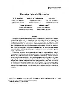
Spatial as an optimised rectangle that is defined by a minimum of two points p1 and p2. An advantage of using an optimised rectangle (or any shape) is that it does not have to be inserted into an Oracle table before it can be used as a query window (Figure 1). The following code excerpt shows how the sdo_relate operator is used to achieve this:
Each CH data point in the database represents a CH artefact and is surrounded by a buffer (the extents of which are also explicitly stored by Oracle Spatial) of varied radius depending on the size and/or significance of the artefact. Taken together the data point and surrounding buffer represent a data area. Justification for placing a buffer around the individual data points rather than around the viewer’s dynamic location in space was one of maximising query optimisation as one of the most important aspects of the query process is the speed at which it is executed. If instead the circular buffer (or indeed any other complex shape) were dynamically generated around the mobile user, the points needed to specify the buffer extents would have to be recalculated each time the user’s context changes in either time or space. An optimised rectangle therefore is the most favourable geometry to query the database against. When the user’s query window intersects a data area in any way, e.g. touch, overlap, etc., the relevant data is placed into a resultset and displayed to the user in the form of text, images, audio, and video files. In the initial implementation it was sufficient to collect data in this manner. The problem here is that the orientation or direction that the viewer is facing is not taken into account when formulating the query. An enhanced implementation extends the initial attempt by adding functionality that allows the query window to be of any required shape. Unlike the initial approach of using an optimised rectangle, the users position shifts to point p1 and it is now required that all the points required to construct the shape-query are specified. Therefore, each point that makes up the optimised shape is now calculated relative to point p1, also called his viewpoint. Although this adds flexibility to the dimensions of the users relevant query space, the problem with this approach is that the query window’s orientation is static, i.e. by changing the orientation of the viewer, simply by rotating about the z-axis, the query window’s position is not affected. This is not an optimal condition as the user is receiving information about data that may be behind them and not what is in their direct field-ofview, i.e. along their line-of-sight.
SELECT A.ID, STREET, BUILDING FROM CHI.CHI_CONTENT_BUFFER A WHERE SDO_RELATE (A.POSITION, MDSYS.SDO_GEOMETRY (2003,NULL, NULL, MDSYS.SDO_ELEM_INFO_ARRAY (1,1003,3), MDSYS.SDO_ORDINATE_ARRAY (X1,Y1, X2,Y2)), 'mask = anyinteract querytype=window') = 'TRUE' ORDER BY ID";
This example shows the sdo_relate operator being used to compare the query window with the CH dataset to determine weather they interact in any way. The sdo_relate operator accepts three parameters, an sdo_geometry column in a table that must be spatially indexed, the query window sdo_geometry and a param list that determines the behaviour of the operator. The query window geometry is defined in the SQL statement string and contains two arrays. The sdo_elem_info_array contains the values that define the type of geometry that is to be queried against the dataset. In this instance it is an optimised rectangle that is defined by a triplet value (1 (offset), 1003 (outer polygon), 3 (optimised rectangle)). The sdo_ordinate_array contains the coordinate values of the rectangle. The mask is set to “anyinteract” which means if any of the topological Boolean predicates return true (or interact) then adds the geometry to the resultset. This SQL string is used to query the spatial database for interaction between the query geometry and the CH data geometries. The query is processed every 5 seconds. If the user is on the move and the position of the user is the same or less than 5m away from the position that the last query was processed, the query will not be run again. When the user’s position is outside this threshold, the query is run again. This significantly reduces the computational cost of redundant queries to the database.
Data Point
Users Position
Optimised Rectangle Query Window
3. p2 1m
p1
Directional Queries
In the enhanced implementation, the method of querying the Cultural Heritage database is more sophisticated. In this approach orientation is a necessary parameter so that the users view-port can be dynamically constructed, resulting in only data contained within the viewers field-of-view (FOV) being returned. This makes querying the data more adaptive; as the user progresses through the VRML world their view-port is being continuously updated with respect to the direction they are facing. The
Data Area
1m
Figure 1: Optimised Rectangle (Window) Query
2
The location of the user's viewpoint, while navigating within the VRML model, is used to simulate the user's position in the real-world streets of Dublin. The virtual 3D coordinates (x,y,z) are transformed into geographic coordinates (φ,λ), the initial interest of the context-based query to the spatial database. In addition to the position, the orientation of the user’s line-of-sight can also be obtained in the same way. The orientation field values provide a rotation axis about which to rotate the viewpoint and a rotation angle specifying the amount by which to rotate around that axis. The first three values in the field specify the X, Y and Z components of the 3D direction vector. The fourth value in the orientation field specifies the positive or negative rotation angle measured in radians [1]. The java class that constructs the query window accepts five parameters and returns three points, those used to implement the window. The five values are those obtained from the EAI. The pseudo-code for the CreateWindow operation is described as Algorithm 1.
query that is formulated in this manner is similar to a standard range query with an optimal shape. As with the standard range query described previously, the query window is compared to an R-tree index. If the query window comes in contact with any of the Minimum Bounding Rectangles (MBRs) of the data areas, the data is said to be intersecting in some way. In our Directional Query Model there are three points defining the triangular query window representing the extents of the user’s field-of-view. The user’s viewpoint p1 is always one of the vertices of the triangle. The points p3 & p4 are calculated by first attaining the azimuth from the 0º North direction to the line-of-sight (LoS) of the user, i.e. to point p2. (Figure 2)
360/0º P3 P2
L1 Lv
270º
L2 P1
P4
90º Algorithm 1: Construct Oriented Query Window
Data Points
Input:
X, Y is the position of the user. Ox, Oy, Oz is the components of the 3D direction vector. Or is the rotation angle around the vector measured in radians. Output: Three points p1, p2, p3.
Viewpoint 180º
Figure 2: Directional Query
Class CreateWindow {
The azimuth of the line-of-sight (Lv) could be obtained either from a VRML browser (as is our case) or from a digital compass embedded within a spatially enabled PDA. To determine the azimuths to points p3 and p4 a specified fraction of an angular FOV value is subtracted from the user’s azimuth Lv to get the azimuth to point p3 and by adding the same fraction of the FOV value to Lv to get the azimuth to point p4. These FOV extents (L1 & L2) are then used to calculate the positions of vertices p3 and p4 on a query buffer of specified radius thus giving the view-port a finite distance. Together, the three vertices are used to produce an optimised spatial query shape that will only select data that is inside a triangle oriented in the same direction as the users line-of-sight. The orientation and position coordinates that are delivered to the java application are obtained by using the External Authoring Interface (EAI) Java Application Programming Interface (API). The EAI is a programming interface for communication between VRML and external programs and allows the developer to register some of the VRML events and properties to the Java programming environment [5,21].
CreateWindow (X, Y, Ox, Oy, Oz, Or){ Angle a = 30; Radius r = 50; toDegrees(Or); //adjustment for reference frame Vector L1 angle = ((Or - a) - 90); //adjustment for reference frame Vector L2 angle = ((Or + a) - 90); Point p1= X, Y; Point p2 = CalcIntersection (L1,r); Point p3 = CalcIntersection (L2,r); Return p1, p2, p3; } CalcIntersction (angle, radius){ Return point; } }
The three points returned from the algorithm are passed into the SQL query string used to query the spatial database. In this example the sdo_elem_info_array is modified to represent a polygon, i.e. the query window.
3
SELECT A.ID, STREET, BUILDING FROM CHI.CHI_CONTENT_DATA A WHERE SDO_RELATE (A.POSITION, MDSYS.SDO_GEOMETRY (2003, NULL, NULL, MDSYS.SDO_ELEM_INFO_ARAY (1,1003,1), MDSYS.SDO_ORDINATE_ARRAY (X1, Y1, X2, Y2, X3, Y3, X1, Y1)),'mask=anyinteract querytype=window') = 'TRUE';
If there is any topological relationship detected the data is returned to a resultset and subsequently displayed to the user. This querying of the database does not take into account the fact that the triangular query window is also interacting with other layers in the database (e.g. the building layer). In reality, if the user is standing on the outside looking into a building, they cannot see what is inside. In our initial implementation of the query model, if the user is standing on the outside they indeed could retrieve data that is unseen to them. As a primary filter this condition is unacceptable when in fact the user only wishes to receive data about objects that they can actually see. Therefore, an option was added that checks to determine if the view-port interacts with any of the building blocks in the block layer of the database. If so, the sub-area of the triangular shaped view-port that overlaps the building polygon should be removed from the query window. This is illustrated in Figure 4 where the shape of the triangular query window has been reduced to the enclosed white and grey space only. The information obtained by performing this check eliminates the building blocks from the viewport while at the same time gives us data on what buildings the view-port is actually intersecting with. This data can then be used to determine if the building blocks involved in the intersection are in the users line-of-sight to other data points in the resultset. Additionally, in comparison with the CH layer, the building block layer also contains attribute information about the individual polygon objects stored in the layer. In the case of the block layer therefore, attributes like the name, address, purpose and associated history of the building are linked to each building object. As such this metadata may be as useful to the user as any other CH artefact and so the line-of-sight algorithm must be applied to the building block layer as well. The solutions to these two problems however are slightly different. In the case of the CH layer, the solution to LoS determination is relatively less complicated than LoS determination of the block layer because the LoS between a viewpoint and a data point requires querying against only a single line. The LoS between the viewpoint and a polygon is more complicated to determine because the number of intersection possibilities are far greater. To determine the LoS for both the CH and block layer a combination of Oracle Spatial operators and a LoS algorithm is required. Our solution was to take a well-known algorithm in Computer Graphics and apply it to the area of Spatial Databases. The scanline algorithm was chosen because the topological and Boolean operations needed to process the algorithm are already inherent in the Oracle database schema.
The sdo_elem_info_array contains the values that define the type of geometry that is to be queried against the dataset. In this instance it is a polygon that is defined by a triplet value (1 (offset), 1003 (outer polygon), 1 (points are connected by straight lines)). In the sdo_ordinate_array the 3 points are specified and the first again to close the polygon. 3.1.
Line-of-Sight
The next objective was to investigate and develop a line-of-sight algorithm to determine if data contained within the view-port is actually in the viewers line-of-sight. This problem is illustrated in Figure 3. The large triangular area in the diagram represents the user’s view-port in 2 dimensions. The brick filled shapes B1, B2, B3, and B4 represent building blocks and D1, D2, D3, and D4 represent CH data points. The enclosed white space in the diagram highlights the desired shape that the line-ofsight algorithm should identify as the query area. The light grey sections represent the areas that should be excluded from the query space, as they are not visible from the user’s viewpoint.
B2 D3
D1 D2
B1
B4
B3
D4 Obstructed Line-of-Sight
Line-of-Sight FOV Viewpoint
Figure 3: Optimised View-Port When the CH database is queried using an oriented view-port, the query simply checks to determine weather any of the CH dataset is in contact with the larger triangular shaped view-port.
4
therefore the processing of the remaining points relating to that particular object is stopped, the ID of the object is placed in the LoS resultset, and the next object is tested. The information on that block therefore is added to the list of objects in the users line-of-sight. In the case where no points of an intersecting object are in the users LoS an additional scan test of the object has to be made to determine for sure that the object is not currently in the user’s FOV. A series of points (e.g. 1m apart) around the perimeter of the block object are calculated. Each point is connected to the viewpoint with a straight line. A scan is run with each of these scanlines to determine if there is any that has no intersection with any other block object, if they all intersect with other objects the block object is clearly not in visible to the user. If there is one scan that doesn’t intersect other block objects, the building object is said to be in view and is added to the users LoS resultset. Only after all the data points and block objects are checked for LoS can the list of objects in the users line-of-sight be supplied to the narrative engine of the system for metadata processing, to create a hyperlinked, digital story based on the events surrounding what the user can see [4]
• Scanline Algorithm – The algorithm works by making a progressive scan of the area in question (field-of-view) to determine weather there are any objects in the scan line path. If so the point at which the scan line intersects the object is recorded. A series of scans is carried out. The end product is the coordinates of a polygon object that represents the search space minus the surrounding building object geometries. Implementing the scanline algorithm for the CH layer is accomplished using Algorithm 2 and the sdo_intersection operator in Oracle. First, a series of lines are created between the viewpoint of the user and each data point present inside the view-port. For the CH layer, these lines are considered as the scanlines. In turn each of the scanlines are used as the input parameters to Algorithm 2, to determine if they interact with any of the objects in the block layer. If there is any interaction between any of the objects in the block layer and the scanline, the CH artefact is not visible to the user from that viewpoint and it will not be placed in the LoS resultset. If there are no interactions between the CH data point and the block layer along that scanline, the data point is considered to be visible and is placed in the LoS resultset. Implementing the scanline algorithm for the block layer is more computationally expensive than the CH data layer. The LoS between a point and a polygon has to be determined, in which case there may be many possible LoS and until there is a positive LoS detected every possibility has to be checked. The process involves initially testing if the view-port interacts with one or more of the building objects in the block layer by using the sdo_intersection operator. If so, the IDs of the objects are put into an array. Oracle’s sdo_difference operator is then used to compute the (spatial) difference between the view-port and the intersecting block object. The sdo_difference operator returns an sdo_geometry object that represents the difference polygon between the two geometries. If there are multiple intersecting objects, the next block object in the array is compared with the result of the previous sdo_difference operation to determine the new difference polygon. This procedure continues until all objects in the array have been processed. The result of this procedure is the view-port in Figure 4 with building blocks B1, B2, B3 and B4 removed, i.e. the shape of the enclosed white and grey space only. The next step in the LoS algorithm is to connect each point of the resulting query space polygon object (each having an associated intersecting object ID) to the viewpoint. In turn each of these scanlines are tested until at least one scan proves negative for intersection with any other object, if so it is evident that there is indeed an unobstructed line-of-sight to that block object and
Algorithm 2: Scan Line Algorithm Input:
Scanline 1 to N Buildings 1 to N
Output: Points of intersection Class ScanLine{ For (each Scanline){ CheckIntersection(scanline, layer); } CheckIntersection(vector scanline, layer lay){ If(scanline interacts with polygon){ return point of intersection } else{ return initial point }}}
4.
3 Dimensional Queries
Adding orientation and LoS (Line of Sight) functionality to the query greatly increases the relevance of the data being returned to the user. Even though this greatly increases the accuracy of the query to the database, the fact that it is still a 2D horizontal query leaves room for enhancement with regards to what the user can actually see in their vertical field-of-view. At present the data that is contained in the CH database has two coordinates associated with it, x and y. This is sufficient because the queries that are being generated only require a 2D point set to
5
port. The height h is the height of the query space and is specified by the user. It has a min value for the height offset and a max value for the height extents of the query space.
query the data. This means that any data that is present within the query view-port will be passed back in the resultset regardless of the height of the users vertical field-of-view. The human Field-of-View (FOV) (Figure 4) spans approximately 200º horizontally taking into account for both eyes and 135º vertically [2]. This limits the amount of data that can be seen at any one time. The normal binocular field-of-view is 120º with and extra 70º of monocular vision (35º each side). The default angle in the our query model is 60º. The user can modify this value interactively as well as the viewing distance to whatever distance they want. The human field-of-view also has an angle of 60º above the direct line of sight and 75º below it. This means that the height of data in the model has to be taken into account as well as the vertical area that is being searched. This can be partially achieved by adding an additional coordinate to each data point in the database giving it height. The z-value is then used as a clause in the spatial query to determine what data is to be subtracted from the initial result set. The view-port can also have on offset height value off the ground ensuring that the space being searched is a true 3 dimensional volume. Adding depth allows queries like “Are there any cultural heritage artefacts contained within the view-port in front of the viewer up to a height of 10 meters off the ground?” and in the second example where the view-port has a height offset, queries like “Are there any cultural heritage artefacts contained within the view-port in front of the viewer that are between 10 and 15 meters off the ground?”
P1
P3
Figure 5: 3D Query Block This approach extends the query model by adding the ability to construct essentially a 3D viewer-based directional query to the search space. The data is then searched by using only topological and metric operations to do so [17]. A second order constraint is then applied to check for height and further reduce the resultset to only the data that satisfies the constraint. 4.1.
View-port Query Control
To give the users control of the desired viewport angle, radius and direction a View-port Query Control was developed (Figure 6). This small frame developed in java gives the user total control of view-port dimensions. The user has the option to change the FOV angle at which the view-port can expand and also the radius it can be extended. The option to modify the orientation of the view-port with reference to the users orientation is also available. Useful while walking down a street but with (query) “eyes” in the back or side of your head for example.
Binocular Field 120º Monocular Field 35º
P4
h
Monocular Field 35º
Blind Area 170º
60º 75º
Figure 6: View-port Query Control Figure 4: Human Field-of-View [2]
It was realised during the development that even though a pie shape view-port is useful it might not always be the preferred option for the user. For
An example of the query space is shown in Figure 5. Point’s p1, p3 and p4 make up the view-
6
example a user might want to query all around them and not just in the field-of-view. To cater for this need a series of tabs were added to the View-port Control. One of these tabs is the buffer tab. There are two spinner controls on this tab that adjust the radius of the view-port to the desired size and the height. (Figure 7)
Virtual Dublin
Spatial CH Database
(φ,λ)
Spatially Enabled PDA
Web Browser
Figure 9: Conceptual Overview of CHI System
Figure 7: Buffer Control
The main technical components are implemented in a three-tier web-based architecture typical of spatially enabled enterprise applications [3], i.e. it comprises three layers, namely the Client Layer, the Application Server Layer, and the Database Layer. All communications between the client layer and the database are conducted through the application server layer. The application, in our case the query building and query results formatting, is executed on the application server. The client communicates with the application server using the existing HTTP networking protocols.
The next tab to be added to the view-port was a static selection control that allows the user to change the orientation of the view-port in relation to the orientation of the user (Figure 8). On this tab the user has a selection of different fields of vision. The default is a human field of view at a height of 2m but a cat (.3m), dog (.5m) or rabbit (.2m) could also be selected to experience these other FOV realities.
5.1.
The client layer consists of spatially enabled mobile devices (Figure 10) that are used to display spatially/semantically relevant CH data about Dublin’s City Centre. Initially, the user's location in space combined with the particular mobile device employed determines the user's context. The purpose therefore of this implementation is to automatically push relevant data from the database layer to the client layer based on this limited contextual view. For CHI, there is a series of three mobile devices simulated within the web browser, plus the web browser that both display to and interact with the user. Choosing to simulate the mobile devices, or user agents, instead of actually implementing on the physical device allow for the accuracy and capabilities of these devices or context sensors to be emulated easily. The devices emulated are a GSM mobile phone, a spatially enabled WAP phone and a spatially enabled PDA.
Figure 8: Select Control The Query Control gives the user the choice to query the CH dataset in three different distinctive ways. Depending on the users personal choice the dataset can be queried over a large area or the query can be narrowed down to a very small sub-region. 5.
Client Layer
Implementation
An overview of the Cultural Heritage Interface (CHI) workflow, developed by the Digital Media Centre of the Dublin Institute of Technology, is illustrated in Figure 9.
7
One advantage of spatial data types is that subsequent queries can be restricted to a pre-defined geographical area, e.g. within a 10m radius of a given location. By exploiting the spatial indexing mechanisms inherent to Oracle 9i, which essentially organises the information within the database tables according to their geographic location, all location relevant data is retrieved most efficiently. The hypermedia CH objects stored in the CHI project database (together with their spatial component) comprise an "historic walking tour of Dublin". Such a tour can begin and end at specific times and places and pass specific landmarks along the way. As each of the landmarks is encountered in turn, a particular "story object" will be retrieved about its historical significance. It is the text of this "story" that will comprise the bulk of the data stored in the CHI database layer. A challenging aspect to this research is the investigation of the methodologies for retrieving these story objects both automatically and coherently as their positions in space are approached. To accomplish this task successfully, the causality of the localised series of events is considered [4].
Figure 10 – Client Layer Display Devices – Cell Phone, WAP Phone, PDA, and Web Browser 5.2.
Database Layer
The database implemented for the CHI project (Oracle 9i) provides spatial object type storage, SQL access, spatial operations, and indexing as well as map projections and coordinate systems support [15]. Through this functionality, spatial queries are efficiently executed without the additional overhead of maintaining coordinate information separate from the attribute data. This is accomplished by defining the attribute information (CH hypermedia) as a spatial data type (which implies associated coordinate data). In the example below the position field is the spatial data type:
A 1
B 2 4
3
C
CREATE TABLE CHI_CONTENT_DATA ( ID NUMBER (20) PRIMARY KEY NOT NULL, POSITION MDSYS.SDO_GEOMETRY NOT NULL, STREET VARCHAR2 (20) NOT NULL, BUILDING VARCHAR2 (20) NOT NULL);
D
Window (Non-Oriented)
(a)
The spatial extension to SQL allows us to use this syntax to create the above table with a spatial data type of type sdo_geometry. It also allows us to insert positional data into the table as follows: INSERT
CH Data
CH Data
A
INTO CHI_CONTENT_DATA VALUES (4, MDSYS.SDO_GEOMETRY (2,NULL, NULL, MDSYS.SDO_GEOMETRY (2001, NULL, MDSYS.SDO_POINT_TYPE (919.0, 513.0), NULL, NULL),‘OCONNELL’, 'GPO');
1
B 2 4
The above code excerpt identifies the object geometry as a 2D Point “2001”, 2 meaning 2D and 1 meaning a point datatype. The coordinates of the point are then specified in the sdo_point_type array. The data in the table is then indexed using the R-tree index data structure that is implemented using the extensible indexing framework of Oracle Spatial [14].
3
C
Window
D
(Oriented)
(b) Figure 11: Comparison of Query Methods
8
The cost of the queries in the revised demonstrator is slightly more than that of the initial prototype due to the first approach using an optimised rectangle to query the data. In the enhanced system the query window is constructed in real-time every five seconds if the viewpoint differs more than 5m in position or more than 30° in direction from the last query processed. The user’s FOV is adjustable in horizontal angle, height and range to accompany many varied points of view The paper introduces a method of developing mobile applications that integrate current technologies thus allowing user-based directional queries to be processed. The specification of a directional data model would greatly improve the synergy of these technologies.
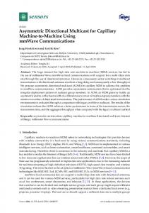
A simple experiment illustrates the performance of the classical range query strategy compared to the view-port directional query strategy (Figure 11). Figure 11(a) illustrates how the CHI spatial database was organised previously and how the data was queried using a range query. Objects A, B, C and D represent street building blocks in the system. The points surrounded by circles represent cultural heritage artefacts (CH data) within the database, each of which are represented by a 2 dimensional point with a buffer. If the Query window interacts with any of the buffers the resulting data set is extracted from the database and presented to the user. A problem with this method is as follows: if the query window is situated in data area 3 and the orientation of the user is northwest the returned data is data point 3, when the actual data should be data point 1. Similarly if the user is facing east the returned data is data 3 when it should be data 4. Our novel solution to this problem is illustrated in figure 11(b). In this example the query window is an oriented and dynamically generated triangle and a 3D point represents each CH data point. The buffers around the data points are no longer necessary because the oriented view-port is being used. If the user’s viewpoint is situated in the same position as the previous example and is also facing northwest, the data that is returned is data point 1 together with Building A metadata (if any) and if the orientation is changed to be east, data point 4 is returned (if visible) plus Building D metadata. The next test considered how accurate the queries would be when querying for height along with horizontal intersection. The SQL query tested for data that was contained within the view-port window and had a height of less than 20m and greater than 10m. This addition to the system means that layers of data can be added to the database with the same X and Y coordinates but a different Z coordinate to distinguish it from data positioned, for example, on different floors of the same building. 6.
7.
Future Work
The next phase of the research is to implement a perspective query frustum (viewpyramid) that will mimic the human field-of-view more accurately, i.e. in 3 dimensions. Determining the line-of-sight of the user in 3 dimensions involves using 3D spatial indexes on 3D objects to determine if 3D data points lie inside the objects. To achieve this, Voxels and Octrees will be considered for indexing the 3D Objects [8,16]. We plan therefore to develop a perspective query [11] processor that will use a proper 3D viewpyramid to query the data taking into account the vertical FOV angle. This approach introduces the concept of querying the CH dataset based on the idea of a “birds-eye-view” of the data. (Figure 12) Achieving this in the VRML world will be relatively straightforward as the viewers direction rotations about the 3 axis are known, however in reality it will need to wait for tilt sensors imbedded in next generation PDA’s.
Conclusion
We have introduced a directional method of querying a spatial database system that considers the user’s line-of-sight in the context of cultural heritage information retrieval. Tests show the enhanced demonstrator performs as expected, with the relevance of the data greatly improved compared to the initial non-directional querying prototype. The determination of the line-of-sight of the user is only a small step in the direction of realistically querying the spatial database. The approach of utilising a scan line intersection algorithm delivers the desired results needed to determine the line of sight but a limitation is that it is specific to 2 dimensional data.
Figure 12: Perspective Query Frustum The approach will consider retrieving all data interacting with the projected footprint of the “floor+base” of the frustum up to any height as a primary filter and then further processing this
9
resultset against a 3D polygonal sweep of specified dimensions from left to right to complete the query and effectively build the view-pyramid in real-time. On the subject of network performance, future work will focus more on reducing the high communication costs between the client and application server due to continuous querying. This might involve reducing the number of queries to the spatial engine or the introduction of predictive querying techniques. Acknowledgements Support for this research from Enterprise Ireland through the Informatics Programme 2001 on Digital Media is gratefully acknowledged.
10
References [1]
[2]
[3]
[4]
[5]
[6]
[12] Papadias, D., Theodoridis, Y., and Sellis, T.: The Retrieval of Direction Relations Using Rtrees. Proc. 5th Int'l Conference on Database and Expert Systems Applications, DEXA'94, Athens, Greece, September 1994. Springer Verlag LNCS #856.
Barfield, W., Hendrix, C., Bjorneseth, O., Kaczmarek, K. A., and Lotens, W.: "Comparison of human sensory capabilities with technical specifications of virtual environment equipment," Presence: Teleoperators and Virtual Environments, 1995.
[13] Pfoser, D., Jensen, C. S., and Theodoridis, Y.: “Novel Approaches in Query Processing of Moving Objects.” In proc. Intl. Conf. on Very Large Databases (VLDB), 2000.
Bertolotto, M., Carswell, J. D., McGeown, L., and McMahon, J., "iSmart+iSIS: Deploying Integrated Web-Based Spatial Applications Within an Oracle Database Environment", International Workshop on Web Geographical Information Systems (WGIS2001), IEEE CS Press, Kyoto, Japan. 2001.
[14] Ravi, K. V. K., Ravada, S., Abugov, D.: “Quadtree and R-tree Indexes in Oracle Spatial: A Comparison using GIS Data”: 2002: Proceedings of the 2002 ACM SIGMOD international conference on Management of data: Pages: 546 – 557.
Carswell, J. D., Eustace, A., Gardiner, K., Kilfeather, E., and Neumann, M.: “An Environment for Mobile Context-Based Hypermedia Retrieval.” DEXA Workshops 2002: 532-536.
[15] Rigaux, P., Scholl, M., and Voisard, A., "Spatial Databases": 2002: Academic Press, Morgan Kaufmann Publishers. pp. 352-360 [16] Samet H., "Application of Spatial Data Structures". Addison-Wesley, 1990.
Diehl, S.: Distributed virtual worlds: foundations and implementation techniques using VRML, Java, and CORBA. Berlin. New York: Springer, 2001.
[17] Shekhar, S., and Chawla, S.: “Spatial Databases: A Tour”: 2003: Prentice Hall Publishers: pp. 28.
Goyal, K. G., and Egenhofer, M. J.: “Similarity of Cardinal Diractions” in: Jensen, C., Schneider, B. S., Seeger. B., Tsotras, V. (eds.): Seventh International Symposium on Spatial and Temporal Databases Lecture notes in Computer Science Vol. 2121, SpringerVerlag, pp. 36-55, July 2001
[7]
Guting, R.H.: “An Introduction to Spatial Database Systems”: 1994: VLDB, 3:357-399.
[8]
Jackins, C., Tanimoto, S. L.: "Oct-Trees and Their Use in Representing Three-Dimensional Objects," CGIP, 14(3), November 1980, 249— 270.
[9]
Technology.http://www.digitalearth.ca/html_p apers/DE_A_064.htm
Ames, A. L., Nadeau, D. R., and Moreland, J.L.: “VRML 2.0 Sourcebook”: 1997: John Wiley and Sons, Inc. pp. 519-531
[18] Shekhar, S., Chawla, S., Ravada, S., Fetterer, A., X. Lui, and Lu, C.T: “Spatial Databases: Accomplishments and Research Needs”: 1999: IEEE Trans. on Knowledge and Data Engineering. [19] Shekhar, S., Liu, X., and Chawla, S.: “An Object Model of Direction And Its Implications”: 1999: GeoInformatica, 3(4), 357-379, Kluwer Academic Publishers. [20] Theodoridis, Y., Papadias, D., and Stefanakis, E.: “Supporting Direction Relations in Spatial Database Systems.” Proc. 7th Int'l Symposium on Spatial Data Handling, SDH'96, Delft, The Netherlands, August 1996.
Liu, X., Shekhar, S., and Chawla, S.: “Objectbased Directional Query Processing in Spatial Databases” accepted to IEEE Transactions of Knowledge and Data Engineering
[21] VRML Consortium: http://www.vrml.org/
[10] Liu, X., Shekhar, S., and Chawla, S.: “Processing Object-orientation-based Direction Queries” in the proceeding of the Eighth International Symposium on Advances in Geographic Information Systems, 69-76, Washington D.C., November 2000. [11] Li, J., Jing, N., and Sun, M.: “Spatial Database Techniques Oriented to Visualisation in 3D GIS.” School of Electronic Science and Engineering, National University of Defense
11