IEEE TRANSACTIONS ON INDUSTRY APPLICATIONS, VOL. 37, NO. 4, JULY/AUGUST 2001
1019
Virtual-Flux-Based Direct Power Control of Three-Phase PWM Rectifiers Mariusz Malinowski, Student Member, IEEE, Marian P. Kazmierkowski, Fellow, IEEE, Steffan Hansen, Member, IEEE, Frede Blaabjerg, Senior Member, IEEE, and G. D. Marques, Member, IEEE
Abstract—In this paper, direct power control (DPC) of three-phase pulsewidth-modulated rectifiers without line voltage sensors is presented. The new system is based on virtual flux (VF) estimation. Theoretical principles of this method are discussed. The steady-state and dynamic behavior of VF-DPC are presented that illustrate the operation and performance of the proposed system compared to a conventional DPC method. Both strategies are also investigated under unbalance and predistorted grid. It is shown that the VF-DPC exhibits several advantages, particularly providing sinusoidal line current when the supply voltage is not ideal. Test results show the excellent performance of the proposed system. Index Terms—Direct power control, instantaneous active and reactive power, pulsewidth-modulated rectifier, virtual flux, voltagesensorless operation. Fig. 1. Simplified representation of a three-phase PWM rectifier system for bidirectional power flow.
I. INTRODUCTION
R
ESEARCH interest in three-phase pulsewidth modulated (PWM) rectifiers (ac/dc converters) has grown rapidly over the past few years due to some of their important advantages, such as power regeneration capabilities, control of dc-bus voltage, low harmonic distortion of input currents, and high power factor (usually, near unity). Various control strategies have been proposed in recent work on this type of PWM converter. Although these control strategies can achieve the same main goals, such as the high power factor and near-sinusoidal current waveforms, their principles differ. Particularly, the voltage-oriented control (VOC), which guarantees high dynamics and static performance via internal current control loops, has become very popular and has constantly been developed and improved [4], [5], [7], [10], [11]. Consequently, the final configuration and performance of the VOC system largely depends on the quality of the applied current control strategy [3]. Another control strategy called direct power control (DPC) is based on the instantaneous active and reactive power control loops [8], [9]. In DPC, there are no internal current control Paper IPCSD 01–016, presented at the 2000 Industry Applications Society Annual Meeting, Rome, Italy, October 8–12, and approved for publication in the IEEE TRANSACTIONS ON INDUSTRY APPLICATIONS by the Industrial Power Converter Committee of the IEEE Industry Applications Society. Manuscript submitted for review July 1, 2000 and released for publication April 27, 2001. M. Malinowski and M. P. Kazmierkowski are with the Institute of Control and Industrial Electronics, Warsaw University of Technology, 00-662 Warsaw, Poland (e-mail:
[email protected];
[email protected]). S. Hansen is with Danfoss Drives A/S, DK-6300 Graasten, Denmark (e-mail:
[email protected]). F. Blaabjerg is with the Institute of Energy Technology, Aalborg University, DK-9220 Aalborg East, Denmark (e-mail:
[email protected]). G. Marques is with the Instituto Superior Tecnico, Technical University of Lisbon, 1049-001 Lisbon, Portugal, (e-mail:
[email protected]). Publisher Item Identifier S 0093-9994(01)05896-0.
9
Fig. 2. Reference coordinates and vectors. : virtual line flux vector; u : converter voltage vector; u : line voltage vector; u : inductance voltage vector; i : line current vector.
loops and no PWM modulator block, because the converter switching states are appropriately selected by a switching table based on the instantaneous errors between the commanded and estimated values of active and reactive power. Therefore, the key point for implementation of the DPC system is a correct and fast estimation of the active and reactive line power. This paper presents a new method of voltage-sensorless power estimation based on a duality with the PWM inverter-fed induction motor where the estimated flux signal is used in the control system. The use of the virtual flux (VF) signal for power estimation leads to the following advantages of the VF-DPC. • Compared to the conventional DPC, there is lower sampling frequency, a simpler voltage and power estimation algorithm, easy implementation of the unbalanced and distorted line voltage compensation to obtain sinusoidal line
0093–9994/01$10.00 © 2001 IEEE
1020
IEEE TRANSACTIONS ON INDUSTRY APPLICATIONS, VOL. 37, NO. 4, JULY/AUGUST 2001
TABLE I SWITCHING TABLE FOR DPC
TABLE II PARAMETERS USED IN SIMULATION STUDY OF VF-DPC
Fig. 3.
Block scheme of VF-DPC.
currents [low total harmonic distortion (THD)] and excellent dynamics. • Compared to the VOC, there is a simpler algorithm, no current control loops, coordinate transformation and separate PWM voltage modulator are not required, there is no need for decoupling between control of the active and reactive components, and there are better dynamics. II. POWER ESTIMATION BASED ON VOLTAGE The main idea of voltage-based power estimation for DPC was proposed in [8]. The instantaneous values of active ( ) and reactive power ( ) are estimated by (1) and (2). It is obvious that the active power is the scalar product of the current and the voltage, whereas the reactive power is calculated as a vector product of them. The first part of both equations represents power in the inductance and the second part is the power of the rectifier
III. POWER ESTIMATION BASED ON VF The VF-based approach has been proposed to improve the VOC [1], [12], [16]. Here, it will be applied for instantaneous power estimation. The voltage imposed by the line power in combination with the ac-side inductors are assumed to be quantities related to a virtual ac motor as shown in Fig. 1. Thus, and represent the stator resistance and the stator leakage inductance of the virtual motor and phase-to-phase line , , and would be induced by a virtual voltages; air-gap flux. In other words, the integration of the phase-to, in staphase voltages leads to a virtual line flux vector tionary – coordinates (Fig. 2). With the definitions (3)
(1) where (4) (2) , and are the switching states of the PWM where rectifier, , , and are the measured line currents, and is the inductance between the grid and the PWM rectifier. In spite of the simplicity of power estimation, this solution possesses several disadvantages such as the following. • High values of the inductance and sampling frequency are needed (an important point for the estimator, because a smooth shape of current is needed). • Power estimation depends on the switching state. Therefore, calculation of the power and voltage should be avoided at the moment of switching, because this gives high errors of the estimated values.
(5)
(6)
(7)
MALINOWSKI et al.: VF-BASED DPC OF THREE-PHASE PWM RECTIFIERS
1021
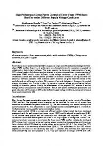
Fig. 4. Simulated basic signal waveforms and line current harmonic spectrum under purely sinusoidal line voltage. (a) Proposed VF-DPC. (b) Conventional DPC presented in [8]. From the top: line voltage, estimated line voltage, line currents, instantaneous active and reactive power, and harmonic spectrum of the line current.
Fig. 6. Block scheme of VF-DPC with PLL generator.
Fig. 5. Simulated waveforms and line current harmonic spectrum under predistorted (5% of fifth harmonic) and unbalanced (4.5%) line voltage for conventional DPC. From the top: line voltage, estimated line voltage, line currents, and harmonic spectrum of the line current.
the voltage equation can be written as (8a)
1022
IEEE TRANSACTIONS ON INDUSTRY APPLICATIONS, VOL. 37, NO. 4, JULY/AUGUST 2001
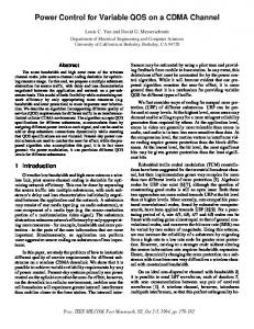
Fig. 7. Transient of the step change of the load (90%). (a) Proposed VF-DPC. (b) Conventional DPC presented in [8]. From the top: line voltage, estimated line voltage, line currents, and instantaneous active and reactive power.
In practice,
can be neglected, which gives (8b)
Using complex notation, the instantaneous power can be calculated as follows: (9a) (9b) where denotes the conjugate line current vector. The line voltage can be expressed by the VF
(10) denotes the space vector and its amplitude. For where , and the the VF-oriented – coordinates (Fig. 2), instantaneous active power can be calculated from (9a) and (10) as (11) For sinusoidal and balanced line voltages, (11) is reduced to (12) (13)
Fig. 8. Simulated basic signal waveforms in the improved VF-DPC (Fig. 6) under predistorted (5% of fifth harmonic) and unbalanced (4.5%) line voltage. From the top: line voltages and line currents with harmonic spectrum.
MALINOWSKI et al.: VF-BASED DPC OF THREE-PHASE PWM RECTIFIERS
1023
(a)
(b)
Fig. 9. Transient to the step change of the load in the improved VF-DPC (Fig. 7). (a) Load increasing. (b) Load decreasing. From the top: line voltages, line currents, and instantaneous active and reactive power. TABLE III SIMULATION RESULTS
which means that only the current components orthogonal to the vector produce the instantaneous active power. Simiflux larly, the instantaneous reactive power can be calculated as (14) and with (12) it is reduced to (15) However, to avoid coordinate transformation into – coordinates, the power estimator for the DPC system should use statororiented quantities, in – coordinates (Fig. 2). Using (9) and (10), (16)
For sinusoidal and balanced line voltage, the derivatives of the flux amplitudes are null. The instantaneous active and reactive powers can be computed as (19a) (19b) IV. BLOCK SCHEME OF DPC The main idea of DPC is similar to the well-known DTC [14], [15]. The basic block scheme of the VF-based DPC system is shown in Fig. 3. Based on the measured dc-link voltage and the converter switch states , , and , the converter voltages are estimated in the block (VFE) as follows: (20a) (20b)
(17) That gives
Then, the VF
components are calculated from (8b) (21a)
(18a)
(18b)
(21b) The measured line currents , and the estimated VF compo, are delivered to the instantaneous power estinents and (delivmator block (PE). The command reactive power ered from the outer PI dc voltage controller) active power values are compared with the estimated and values, in reactive and active power hysteresis controllers, respectively.
1024
Fig. 10.
IEEE TRANSACTIONS ON INDUSTRY APPLICATIONS, VOL. 37, NO. 4, JULY/AUGUST 2001
Scheme of laboratory setup.
V. SIMULATION RESULTS
TABLE IV ELECTRICAL PARAMETERS
The digitized output signal of the reactive power controller are defined as for for
(22a) (22b)
and, similarly, of the active power controller as for for
(23a) (23b)
and are the hysteresis band. where and the flux vector position The digitized variables , form a digital word, which by accessing the address of the lookup table selects the appropriate voltage vector according to the switching Table I. The region of the flux vector position is divided into 12 sectors. It means that areas between adjoining vectors contain two and sector is closer to sectors, where sector is closer to .
To study the operation of the VF-DPC system under different line conditions and to carry out a comparative investigation, the PWM rectifier with the whole control scheme has been simulated using SABER software. The main electrical parameters of the power circuit and control data are given in Table II. The simulation study has been performed with two main objectives in mind: • explaining and presenting the steady-state operation of the proposed VF-DPC with a purely sinusoidal and distorted unbalanced supply line voltage, as well as performance comparison with the conventional scheme where the instantaneous power is estimated based on calculated voltage (not VF) signals [8]; • presenting the dynamic performance of power control. The simulated waveforms for the proposed VF-DPC and for the DPC reported in [8] are shown in Fig. 4. These results were obtained for purely sinusoidal supply line voltage. Similarly, Fig. 5 shows an oscilogram for distorted (5% of fifth harmonic) and unbalanced (4.5%) line voltages. The dynamic behavior under a step change of the load is presented in Fig. 7. Note that, in spite of the lower sampling frequency (60 kHz), the VF-based power estimator gives much less noisy instantaneous active and reactive power signals [Fig. 7(a)] in comparison to the conventional DPC system with 80-kHz sampling frequency [Fig. 7(b)]. This is thanks to the natural low-pass filter behavior of the integrators used in (21) and the (because th harmonics are reduced by a factor ripple caused by high-frequency power transistor switching is effectively damped). Consequently, the derivation of the line current, which is necessary in conventional DPC for sensorless
MALINOWSKI et al.: VF-BASED DPC OF THREE-PHASE PWM RECTIFIERS
Fig. 11.
Line voltage with harmonic spectrum (u : line voltage; u
1025
: distortion from purely sinusoidal supply line voltage).
Fig. 12. Experimental waveforms with distorted line voltage for conventional DPC. From the top: line voltage, line currents (5 A/div), and estimated VF.
Fig. 13. Experimental waveforms with distorted line voltage for VF-DPC. From the top: line voltage, line currents (5 A/div), and estimated VF.
voltage estimation, is eliminated in the VF-DPC. However, the dynamic behavior of both control systems is identical (see Fig. 7). VI. IMPROVED VF-BASED DIRECT POWER CONTROL WITH PHASE-LOCKED LOOP (PLL) GENERATOR Further improvements regarding VF-DPC operation can be achieved by using a sector detection with PLL generator instead of a zero-crossing voltage detector (Fig. 6). This guarantees a very stable and free-of-disturbances sector detection, even under operation with distorted and unbalanced supply line voltages (Fig. 8). Fig. 8 shows that VF-DPC provides sinusoidal line current as well at distorted and unbalanced supply voltage. The excellent dynamic properties of the improved VF-DPC system of Fig. 6 are shown in Fig. 9. The results of the simulation study are summarized in Table III. VII. EXPERIMENTAL RESULTS The laboratory setup (Fig. 10) consists of two commercial Danfoss inverters, VLT 5000 series (5.2 kVA), controlled by the dSpace DS1103 board inserted into a PC-Pentium
Fig. 14. Experimental waveforms with distorted line voltage for VF-DPC. From the top: line voltage, line currents (5A/div) and instantaneous active (2 kW/div) and reactive power (2 kvar/div), and harmonic spectrum of line current (THD 5, 6%).
=
1026
IEEE TRANSACTIONS ON INDUSTRY APPLICATIONS, VOL. 37, NO. 4, JULY/AUGUST 2001
• • • • • •
lower sampling frequency (as conventional DPC [8]); sinusoidal line currents (low THD); no separate PWM voltage modulation block; no current regulation loops; coordinate transformation not required; high dynamic, decoupled active and reactive power control.
The typical disadvantages are the following: • variable switching frequency; • solution requires a fast microprocessor and A/D converters. As shown in this paper, thanks to duality phenomena, an experience with the high-performance decoupled PWM inverter-fed induction motor control can be used to improve properties of the PWM rectifier control. Fig. 15. Transient of the step change of the load in the improved VF-DPC (Fig. 7), load increasing. From the top: line voltages, line currents (5 A/div), and instantaneous active (2 kW/div) and reactive power (2 kvar/div).
and a 3-kW induction motor or resistor as a load. The main electrical parameters of the power circuit and control data are given in Table IV. The mixed RISC/DSP digital controller based on two microprocessors (PowerPC604e—333 MHz and TMS320F240—20 MHz) and four high-resolution analog-to-digital (A/D) converters (0.8 s—12 b) provide very fast processing for floating-point calculations. The experimental results are done for a significantly distorted line voltage, which is presented in Fig. 11. Steady-state operation for DPC and VF-DPC are shown in Figs. 12–14. The shape of the current for conventional DPC is strongly distorted because the following two undesirable conditions are applied: • sampling time was 20 s (should be about 10 s [8]); • voltage was not purely sinusoidal. VF-DPC in comparison with the conventional solution at the same condition provides sinusoidal current (Figs. 13 and 14) and low THD. The dynamic behavior under a step change of the load for VF-DPC is shown in Fig. 15.
VIII. CONCLUSION The presented DPC system constitutes a viable alternative to the VOC of PWM rectifiers. Based on duality with a PWM inverter-fed induction motor, a new method of instantaneous active and reactive power calculation has been proposed. This method uses the estimated VF vector instead of the line voltage vector in the control. Consequently, voltage sensorless line power estimation is much less noisy thanks to the natural low-pass behavior of the integrator used in the calculation algorithm. Also, differentiation of the line current is avoided in this scheme. Therefore, the presented VF-DPC of PWM rectifier has the following features and advantages: • no line voltage sensors required; • simple and noise-robust power estimation algorithm, easy to implement in a digital signal processor (DSP);
REFERENCES [1] J. L. Duarte, A. Van Zwam, C. Wijnands, and A. Vandenput, “Reference frames fit for controlling PWM rectifiers,” IEEE Trans. Ind. Electron., vol. 46, pp. 628–630, June 1999. [2] S. Hansen, M. Malinowski, F. Blaabjerg, and M. P. Kazmierkowski, “Control strategies for PWM rectifiers without line voltage sensors,” in Proc. IEEE APEC 2000, vol. 2, 2000, pp. 832–839. [3] M. P. Kazmierkowski and L. Malesani, “Current control techniques for three-phase voltage-source PWM converters: A survey,” IEEE Trans. Ind. Electron., vol. 45, pp. 691–703, Oct. 1998. [4] M. P. Kazmierkowski, M. A. Dzieniakowski, and W. Sulkowski, “The three phase current controlled transistor DC link PWM converter for bi-directional power flow,” in Proc. PEMC Conf., Budapest, Hungary, 1990, pp. 465–469. [5] H. Kohlmeier, O. Niermeyer, and D. Schroder, “High dynamic four quadrant AC-motor drive with improved power-factor and on-line optimized pulse pattern with PROMC,” in Proc. EPE Conf., Brussels, Belgium, 1985, pp. 3.173–178. [6] V. Manninen, “Application of direct torque control modulation technology to a line converter,” in Proc. EPE Conf., Seville, Spain, 1995, pp. 1.292–1.296. [7] O. Niermeyer and D. Schroder, “AC-motor drive with regenerative braking and reduced supply line distortion,” in Proc. EPE Conf., Aachen, Germany, 1989, pp. 1021–1026. [8] T. Noguchi, H. Tomiki, S. Kondo, and I. Takahashi, “Direct power control of PWM converter without power-source voltage sensors,” IEEE Trans. Ind. Applicat., vol. 34, pp. 473–479, May/June 1998. [9] T. Ohnishi, “Three-phase PWM converter/inverter by means of instantaneous active and reactive power control,” in Proc. IEEE IECON’91, 1991, pp. 819–824. [10] B. T. Ooi, J. C. Salmon, J. W. Dixon, and A. B. Kulkarni, “A 3-phase controlled current PWM converter with leading power factor,” in Conf. Rec. IEEE-IAS Annu. Meeting, 1985, pp. 1008–1014. [11] B. T. Ooi, J. W. Dixon, A. B. Kulkarni, and M. Nishimoto, “An integrated AC drive system using a controlled current PWM rectifier/inverter link,” in Proc. IEEE PESC’86, 1986, pp. 494–501. [12] P. J. M. Smidt and J. L. Duarte, “An unity power factor converter without current measurement,” in Proc. EPE Conf., Seville, Spain, 1995, pp. 3.275–3.280. [13] P. Barrass and M. Cade, “PWM rectifier using indirect voltage sensing,” Proc. IEE—Elect. Power Applicat., vol. 146, no. 5, pp. 539–544, 1999. [14] M. Depenbrock, “Direct self-control (DSC) of inverter-fed induction machine,” IEEE Trans. Power Electron., vol. 3, pp. 420–429, Oct. 1988. [15] I. Takahashi and Y. Ohmori, “High performance direct torque control of an induction motor,” in Conf. Rec. IEEE-IAS Annu. Meeting, 1987, pp. 163–169. [16] M. Weinhold, “A new control scheme for optimal operation of threephase voltage dc link PWM converter,” in Proc. PCIM Conf., 1991, pp. 371–383.
MALINOWSKI et al.: VF-BASED DPC OF THREE-PHASE PWM RECTIFIERS
Mariusz Malinowski (S’99) was born in Radom, Poland, in 1972. He received the Msc.EE. degree in 1997 from Warsaw University of Technology, Warsaw, Poland, where he is currently working toward the Ph.D. degree in the Institute of Control and Industrial Electronics. His current research activity deals with control of PWM rectifiers, modulation, and DSP techniques. Mr. Malinowski received a Best Paper Award at IEEE IECON 2000. He is a Scholar of the Foundation for Polish Science.
Marian P. Kazmierkowski (M’89–SM’91–F’98) received the M.Sc., Ph.D., and Dr.Sc. degrees in electrical engineering from the Institute of Control and Industrial Electronics, Warsaw University of Technology, Warsaw, Poland, in 1968, 1972, and 1981, respectively. From 1967 to 1969, he was with the Industrial Research Institute of Electrotechnics (IE1), Warsaw, Poland, and from 1969 to 1980, he was with the Institute of Control and Industrial Electronics, Warsaw University of Technology, as an Assistant Professor. From 1980 to 1983, he was with RWTH Aachen, Aachen, West Germany, as an Alexander von Humboldt Fellow. During 1986–1987, he was a Visiting Professor at NTH Trondheim, Trondheim, Norway. Since 1987, he has been a Professor and Director of the Institute of Control and Industrial Electronics, Warsaw University of Technology. He was a Visiting Professor at the University of Minnesota, Minneapolis, in 1990, at Aalborg University, Aalborg East, Denmark, in 1990 and 1995, and at the University of Padova, Padova, Italy, in 1993. He was also a Coordinating Professor in the International Danfoss Professor Program at Aalborg University for 1997–2000. Since 1996, he has served as an elected member of the State Committee for Scientific Research in Poland. He is engaged in research and theoretical work on electrical drive control and industrial electronics. He is the author or coauthor of more than 140 technical papers and reports, as well as 11 books and textbooks. His latest book, with Dr. H. Tunia, is Automatic Control of Converter-Fed Drives (Amsterdam, The Netherlands: Elsevier, 1994). Dr. Kazmierkowski was Chairman of the 1996 IEEE International Symposium on Industrial Electronics held in Warsaw, Poland. He is an Associate Editor of the IEEE TRANSACTIONS ON INDUSTRIAL ELECTRONICS, a Vice President of the IEEE Industrial Electronics Society, and the IEEE Industrial Electronics and IEEE Power Electronics Societies Joint Chapter Chairman of the IEEE Poland Section.
Steffan Hansen (S’95–A’96–M’99) was born in Sonderburg, Denmark, in 1971. He received the M.Sc. degree in electrical engineering from Aalborg University, Aalborg East, Denmark, and the Ph.D. degree, under an industrial Ph.D. fellowship supported by Danfoss Drives A/S and the Danish Academy of Technical Sciences, from the Institute of Energy Technology, Aalborg University, in 1996 and 2001, respectively. Since 1996, he has been with Danfoss Drives A/S, Graasten, Denmark, where he currently is a Staff Member in the Research and Development Department. His research interests are active rectifiers and filters, harmonic current and voltage distortion of diode rectifiers, and power converter topologies for improved harmonic performance.
1027
Frede Blaabjerg (S’86–M’88–SM’97) was born in Erslev, Denmark, in 1963. He received the Msc.EE. degree from Aalborg University, Aalborg East, Denmark, and the Ph.D. degree from the Institute of Energy Technology, Aalborg University, in 1987 and 1995, respectively. He was with ABB-Scandia, Randers, Denmark, from 1987 to 1988. He joined Aalborg University in 1992 as an Assistant Professor and became an Associate Professor in 1996 and a Full Professor in power electronics and drives in 1998. His research areas are power electronics, static power converters, ac drives, switched reluctance drives, modeling, characterization of power semiconductor devices, and simulation. He is involved in more than 15 research projects with industry. Among them is the Danfoss Professor Programme in Power Electronics and Drives. He has authored more than 200 publications in his research fields. He is an Associate Editor of the Danish journal, Elteknik. Dr. Blaabjerg is a member of the European Power Electronics and Drives Association and the Industrial Drives Committee of the IEEE Industry Applications Society. He is also a member of the Industrial Power Converter and the Power Electronics Devices and Components Committees of the IEEE Industry Applications Society. He is an Associate Editor of the IEEE TRANSACTIONS ON INDUSTRY APPLICATIONS. He serves as a member of the Danish Technical Research Council in Denmark and of the board of the Danish Space Research Institute. He became a member of the Danish Academy of Technical Science in 2001. He received the 1995 Angelos Award for his contribution in modulation technique and control of electric drives, and an Annual Teacher Prize from Aalborg University, also in 1995. In 1998, he received the Outstanding Young Power Electronics Engineer Award from the IEEE Power Electronics Society and an IEEE TRANSACTIONS ON POWER ELECTRONICS Prize Paper Award for best paper published in 1997. Finally, he received two Prize Paper Awards at the IEEE Industry Applications Society Annual Meeting in 1998.
G. D. Marques (M’95) was born in Benedita, Portugal, in 1958. He received the Dipl. Ing. and Ph.D. degrees in electrical engineering from the Technical University of Lisbon, Lisbon, Portugal, in 1981 and 1988, respectively. Since 1981, he has been with the Instituto Superior Técnico, Technical University of Lisbon, where he teaches on the topic of electrical machines in the Department of Electrical and Computer Engineering. He is currently an Associate Professor. His research interests include electrical machines, static power conversion, variable-speed drive and generator systems, harmonic compensation systems, and nonlinear dynamical systems.