Neurosurg Focus 8 (6):JNS Preview Article, 2000, Click here to return to Table of Contents
Virtual image navigation: a new method to control intraoperative bleeding in neuroendoscopic surgery MARTIN SCHOLZ, M.D., BRITTA FRICKE, M.D., STEPHAN TOMBROCK, MARKUS HARDENACK, M.D., KIRSTEN SCHMIEDER, M.D., PH.D., MONIKA VON DÜRING, M.D., PH.D., WOLFGANG KONEN, PH.D., AND ALBRECHT HARDERS, M.D., PH.D. Departments of Neurosurgery and Neuroanatomy, Ruhr-University Bochum, and Center of Neuroinformatics, Bochum, Germany Object. In this neuroendoscopic study the authors tested the newly developed "red-out module" of their visual navigation system that enables the neurosurgeon to achieve hemostasis if total visualization is lost due to hemorrhage ("red out") within the visual field. Methods. An optical position measurement system, connected to the endoscope, guarantees that digitized endoscopic images are coupled with the accurate endoscopic position. Computerized images are simultaneously stored with their respective position data, and this creates a virtual anatomical landscape. The system was tested in in vivo bleeding conditions in a rat model. Artificial endoscopic cavities were created in the inguinal, pelvic, and jugular regions of the rat to imitate the conditions of the human ventricular system. Two different experimental settings were tested: Technique I in which a computer landmark has been previously determined at the point where the vessel will be lesioned; and Technique II in which a landmark has been previously set in the surrounding area of the vessel. Immediately after hemorrhage obscures the visual field ("red out"), the computer automatically displays the virtual images on a separate monitor. The previously set landmarks and the graphic overlay of the coagulation fiber enable the surgeon to navigate within the operative field based on the virtual images and to perform coagulation at the site of the lesion. A total of 175 vessels were coagulated: 43 arteries and 132 veins. In using Technique I 130 (90.9%) of 143 vessels and in using Technique II 26 (81.3%) of 32 arteries were successfully coagulated. Conclusions. The authors’ data revealed that virtual image guidance has the potential to be a helpful tool in neuroendoscopy.
KEY WORDS • neuronavigation • endoscopy • coagulation • rat
In recent years several image-guided navigation systems that use preoperative 3D datasets and achieve a high degree of accuracy have improved intraoperative orientation in neuroendoscopic surgery17,22 and microsurgery.3,11,27 These systems make use of preoperative data and are helpful in focusing on the ROI.6 However, various intraoperative conditions such as tissue displacement caused by a loss of cerebrospinal fluid or by surgical reduction of a space-occupying lesions are not taken into consideration. Consequently there is demand for a realtime endoscopic navigation system. Intraoperative CT scanning,14 MR imaging,18,24 or ultrasonography21,30 were first used in attempt to acquire real-time imaging data.
Abbreviations used in this paper: CT = computerized tomography; MR = magnetic resonance; OPMS = optimum position measurement system; ROI = region of interest; VN = visual navigation; 3D = three dimensional.
Neurosurg. Focus / Volume 8 / June, 2000
One of the important limitations of minimally invasive surgical methods in general is a complete loss of the realtime endoscopic visualization when hemorrhage is inadvertently caused ("red out"), as in cases in which bleeding occurs after a tumor biopsy sample is obtained. (Click here to view Video 1, [Patient_A.AVI 4 MB]) Until now, the only counter measures available have been indirect methods such as continuous irrigation. Additionally, if this has not been effective, the removal of the endoscope without knowledge of orientation carries the risk of causing severe tissue damage. In such cases an adequate tool to achieve hemostasis19 by direct coagulation of the bleeding vessel would improve the safety of endoscopic procedures and would help to avoid major complications.28 Using the VN system,13,25 we are now able to record all video images during an endoscopic procedure. This includes being able to map interesting anatomical landmarks, as well as the position of the endoscope tip in a computerized dataset. In comparison with other navigation systems,4,10 the VN sys1
M. Scholz, et al. tem offers the advantages of intraoperative calibration and digitalization of all video data, which can be used in different image-control modules. Using standard camera calibration techniques29 and a newly developed system calibration,16 any 3D point can be mapped within the visual field of the endoscope. In cases in which visualization is completely lost, the VN system automatically supports the surgeon by displaying on a computer screen the virtual images previously stored (“red-out module”). Computergenerated calculations demonstrating the endoscopes exact position and the previously stored endoscopic images allow the surgeon to navigate the endoscope in a virtual setting. The aim of our experimental study was to test the potential uses and limitations of this new tool in standarized bleeding conditions in a rat ventricular model. The efficacy of successful coagulation and the accuracy following artificially induced bleeding were analyzed in this in vivo model.
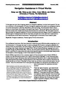
Fig. 1. Photograph showing the surgically created cavum in the inguinal region with the endoscope in place.
MATERIALS AND METHODS Testing the potential of the VN system to control intraoperative bleeding required that we induce hemorrhagic conditions in an in vivo mammalian model. Thus, an artificial endoscopic cavity was created in the inguinal, pelvic, and jugular regions, in which vessels of different calibers (comparable with the diameter of human intracerebral vessels) could be punctured to induce bleeding. Depending on the experimental conditions, three to 10 puncture wounds were produced in each animal. All experiments were performed by a team of three investigators: a neurosurgeon who performed the endoscopic navigation, an assistant responsible for guiding of the coagulation fiber, and an engineer to control the VN computer. Twenty-five adult Wistar rats (13 female and 12 male) weighing 215 to 313 g were deeply anesthetized with sodium pentobarbital and fixated on a dissecting table. After the incision was made in the inguinal, jugular, and pelvic regions, skin and hypodermis were dissected from the underlying body fascia. In the pelvic region two retractors were inserted, and the ascending colon was lifted and fixed at the abdominal wall to gain access to the retroperitoneal space. To create an artificial cavity of 5 to 8 cm3 the margins of the surgical wound were lifted and fixed on a specially designed device placed 8 cm above the level of the dissecting table (Fig. 1). The wall of the saphenous artery and vein, epigastric vein, abdominal aorta, inferior vena cava, common iliac artery, and jugular vein were exposed by dissecting the surrounding connective tissue. To make additional analyses and measurements easier we set marker points in the surrounding tissue of the vessels by using a waterproof pen. The artificial cavum was filled with prewarmed Ringer’s solution adapted to the body temperature of the animal. The experiments were conducted according to the regulations of the European Convention for the Protection of Vertebrate Animals for Experimental and other Scientific Purposes and were controlled by the Animal Care Committee of the Ruhr-Universität. A rigid endoscope (Camaert/Wolf, 5.9-mm outer diameter), with three infrared (light-emitting diodes) placed 18 cm from the tip of the endoscope, was fixed with a special
device (Magic Arm, Philips [Author: city/state/country?]) allowing free movements in a 3D space. The positions of the infrared light-emitting diodes are measured by the OPMS, which is part of the EasyGuide Neuro navigation system. (Philips Medical Systems, Best, The Netherlands). The endoscopic images were continuously registered at a frequency of two per second, digitalized on a frame grabber, and stored as a computerized dataset including the OPMS position data of the endoscope. The experimental setting is shown in Fig. 2 left. Using standard camera calibration techniques28 and a newly developed system calibration, any 3D point registered by the endoscope can be mapped. In particular, the system displays the coordinates of any anatomical landmark in the ROI as it is viewed from the current position of the camera. Another important feature of the “red-out module” is that the virtual map is automatically updated with new position data each time a previously stored 3D point is passed again. Successful coagulation requires not only good spatial resolution within the camera plane but also a high accuracy in the depth direction, such as along the optical axis. The principle of depth measurement in the VN system is shown in Fig. 2 right. We take advantage of the fact that the endoscope position is known from the tracking digitizer (OPMS) with good accuracy and perform triangulation to obtain the 3D positions of landmarks. This procedure has been used in many preclinical and clinical tests and has been found to be accurate and reliable.13,25 The accuracy is directly related to the opening angle. In a previously published study we showed that small movements (of several millimeters) of the endoscope are sufficient to obtain an opening angle (larger than 7.5°) and that with such opening angles a depth accuracy of 0.25 to 0.50 mm can be achieved.25 This degree of accuracy is comparable with that of the tracking digitizer (OPMS), which is in the order of 0.3 mm and poses, therefore, the current limitation on optimizing the accuracy of the technique. However, an accuracy of 0.25 to 0.50 mm is sufficient for the current application in the “red-out module” because the diameter of the coagulation fiber is 2.0 mm. In cases in which image loss occurs, the virtual mode of
2
Neurosurg. Focus / Volume 8 / June, 2000
Virtual image navigation for coagulation
Fig. 2. Left: Schematic drawing of system arrangement: the computer with frame grabber (1), Live-display on VGA monitor (2), rigid 5.9-mm endoscope (3), charged-coupled device camera (4), OPMS (5). Right: Drawing depicting the principle of depth measurement in the VN system. A certain landmark P is seen from two different views of the endoscopic camera. Point P is observed in both views at pixel positions x1 and x2, respectively. If the opening angle is larger than zero, then the depth of point P (that is, its distance along the optical axis) can be calculated from the observable factors x1 and x2 by triangulation.
the VN system requires the storage of images. Images are stored together with the 3D position of the endoscope tip and the frontoparallel rotation angle at a rate of approximately 2 Hz. In principle, all three degrees of rotation would be needed to characterize a camera view uniquely. However, for a given 3D position of the endoscope tip the endoscope provides virtually only the frontoparallel rotation degree of freedom because the endoscope shaft is guided through the burr hole. Currently we undertake a fast procedure for image storage and retrieval: in storage mode, the operating space is divided into voxels of 0.5mm side length, and for each visited voxel one image is stored. Once the endoscope tip passes again through a previously visited voxel, the previous image is overwritten by the new one. In the virtual mode (retrieval mode) the surgeon sees the image of the voxel where the endoscope tip is localized. If the current frontoparallel rotation angle differs from that of the stored rotation angle, the image will be properly rotated (in-plane) to the current rotation angle. (In the future version of the VN system, we plan to fine tune this strategy further by allowing the ability to interpolate between stored images to obtain a smooth movement and by refining the voxel discretization. It has turned out, however, that this rather simple strategy already provides the surgeon with most of the information he or she needs.) To test the potential and limitations of the virtual image guidance system, two different experimental settings were used. Technique I, a biopsy technique, was developed to relocate a point of danger in the event that bleeding obscures the visual field, as in the case of biopsy sampling. The system provides a virtual anatomical map so that the surgeon can locate the side of bleeding and perform coagulation especially at this area. Technique II, the security technique, was developed following the good results obNeurosurg. Focus / Volume 8 / June, 2000
tained with Technique I and was designed to simulate an accidental bleeding in the visual field. Technique I (Biopsy Technique) A computer-registered landmark was determined directly at the point where the vessel was to be lesioned (Fig. 3). Prior to induction of bleeding, the diameter of the arterial or venous vessel was measured using graph paper. A computerized landmark was directly set at the selected point of the vascular lesion. The lesion was induced by a sharp lancet (generally used to collect blood samples for glucose measurements) mounted at the tip of a Fogarty catheter located in the working channel of the endoscope. Severe hemorrhage caused a complete loss of visualization registered by the red detector of the computer system. To achieve a complete “red out,” red ink was added immediately to the Ringer’s solution after induction of bleeding in those cases in which a less pronounced hemorrhage occurred. The computer automatically displayed the virtual images on a separate monitor in addition to the online video image. The endoscope was completely dislocated after induction of bleeding, thus ensuring that the neurosurgeon relies only on the virtual images of the VN system for manipulating the endoscope. The previously set landmark and the marker displaying the current position of the endoscope tip on the computer screen were adjusted in the same position. To stop the bleeding, a coagulation fiber with a millimeter scale on its outer surface (2-mm diameter) was carefully removed from the endoscope in a distance calculated by the measurement mode of the computer. The coagulation (1 second, 15 mA) was performed by a bipolar coagulation device (Erbotom/Erbe Tubingen, Germany). The time between the onset of bleeding and coagulation was documented. After each trial, the endoscopic
3
M. Scholz, et al. The ROI and the surrounding area were inspected using the endoscope to acquire a large number of images (stored at a frequency of two/second). After induction of bleeding and complete image loss, the surgeon navigates the endoscope in the virtual images, guiding the graphic overlay of the coagulation fiber into the ROI where the bleeding started. Analysis of the coagulation results was performed using the same method as that described in Technique I. Technique II requires that the neurosurgeon realize the bleeding region in the last moment before bleeding completely obscures the visual field. The neurosurgeon has to locate this region by viewing the virtual images. Cases of bleeding with a very sudden complete image loss cannot be managed using this technique, although this complication can be managed using Technique I.
Fig. 3. Technique I. Images obtained using the VN system. Upper: Target directly over the junction of the iliac artery. Center: Virtual image with graphic overlay of the coagulation fiber. Lower: Control of the lesion after coagulation. Blue cross indicates the previously set landmark at the point of intervention.
cavity was rinsed with the prewarmed Ringer’s solution to inspect the coagulation results. Technique II (Security Technique)
Technique II was devised as a security technique in which the landmark is outside the point of damaged vessel but within the visual field (Fig. 4). This setup simulates the occurrence of an unexpected intraoperative hemorrhage in the visual field. A computer landmark was determined for safety purposes in the surrounding area of the vessel, but no additional landmark was set at the site of the lesion. The distance between landmark and prospective lesion was measured. 4
RESULTS This new animal model was created to simulate operative endoscopic conditions. The coagulated vessels had a diameter of 0.5 to 1.5 mm (Table 1). One hundred seventy-five vessels were coagulated: 43 arteries and 132 veins. In 143 cases we followed the procedures of Technique I with direct landmark positioning. In 32 cases a security landmark was set within the endoscopic visual field but outside of the vessel itself (Technique II). In 156 (89.1 %) of all cases successful coagulation with cessation of bleeding was obtained. A comparison of the efficacy of successful coagulation achieved using Techniques I and II produced several results. With Technique I 130 (90.9%) of 143 vessels could be coagulated. With Technique II bleeding in 26 (81.3%) of 32 vessels was stopped. In cases of successful coagulation the center of the coagulation field was not identical to that in the vascular lesion in all cases (Tables 2 and 3). Occasionally excentric coagulations occurred, but in most of these cases the cessation of bleeding was obtained because of the diameter of the coagulation fiber (2 mm). Figure 3 gives an example of the coagulation procedure involved in Technique I. Figure 4 shows a typical coagulation procedure when using Technique II. Click here to view Video 2 [Redout01A.AVI 6.8 MB] Click here to view Video 3 [Redout02A.AVI 17.5 MB] Click here to view Video 4 [Redout1_A.AVI 5.2 MB] In six cases a false “red out” alarm was detected that was caused by the red background color of the surrounding tissue. The time between induction of bleeding and successful coagulation (bleeding time) was registered in all cases and ranged from 16 to 130 seconds for Technique I and from 23 to 186 seconds for Technique II. A correlation between the experience of the investigator using the navigation system and the time between induction and successful coagulation of bleeding was obvious because the surgeon needed much longer in the first experiments than in later experiments. An example of the coagulation time in Technique I, in which a real learning curve is demonstrated, is shown in Fig. 5 upper, and an example of the same is given in Fig. 5 lower. Control Group
The time course of hemostasis without control of coagulation was measured in nine experiments. In eight of nine Neurosurg. Focus / Volume 8 / June, 2000
Virtual image navigation for coagulation
Fig. 4. Technique II. Images obtained using the VN system. Upper Left: Sites with security landmark (blue cross) and target vessel in the upper part of the endoscopic image. Upper Right: Lesioning of the vessel performed using a lancet. Center Left: Virtual backround with graphic overlay of the coagulation fiber. Center Right: A “red-out” situation in which normally intervention is not possible due to inadequate visualization. The yellow t indicates the direction of the security landmark when it is outside of the visual field. Lower Left: Clarity of visualization after coagulation with security landmark (blue cross). Lower Right: Enlarged image of the coagulation point, showing complete occlusion of the target vessel.
vessels bleeding had to be stopped surgically by performing normal coagulation procedures or applying swabs to prevent major blood loss in the animal after 131 to 228 seconds (average 178.7seconds). One episode of venous bleeding ceased after 100 seconds when a hematoma spontaneously formed. In the light of the data depicted in Fig. 5, it is obvious that the coagulation time was longer than 100 seconds in only six of 175 cases (3.4%). DISCUSSION There are numerous surgical situations that limit a more extensive application of neuroendoscopy because of parNeurosurg. Focus / Volume 8 / June, 2000
tial or complete visual loss.2,5,31 In such cases opaque fluid, lens dislocation,9 tissue covering the lens, and hemorrage (“red out”) make neuronavigation impossible. We have shown that successful neuroendoscopic coagulation, however, can be achieved in a “red-out” situation by the application of new methods in digital image processing.13 It is important to note that the term “virtual endoscopy” was previously reserved for special diagnostic procedures in which patient-specific high-resolution digital images are obtained with MR imaging or a helical CT scanning.1 Individual structures can be graphically isolated or “segmented” into fully interactive 3D reconstructions on a computer screen. This method has its role in preoperative 5
M. Scholz, et al. TABLE 1 Different vessel regions used in the coagulation precedures Vessel (diameter in mm)
No. of Cases
saphenous vein ( 0.5–0.75) epigastric vein (0.5–0.75) saphenous artery (0.5) jugular vein (1–1.5) vena cava (1) aorta (1.5) iliac artery (1) total
Target to Coagulation Point Distance (mm)
90 36 21 5 1 9 13 175
planning. However, it is associated with several disadvantages: artifacts can be introduced because current point resolution of MR imaging is not higher than 1 to 2 mm. Relevant structures in endoscopy15,20 such as membranous structures are much thinner and smaller. Furthermore, intraoperative neuroimaging until now was only partially suitable because of the technical hindrances and limited image quality. Furthermore, preparation of radiological virtual datasets is time consuming due to the time it takes to complete imaging studies in patients. Bricault, et al.,4 have developed a new method by which imaging data obtained from CT slices and bronchoscopic video sequences can be fused. In this computer-guided transbronchial biopsy system a special segmentation process, in which mathematical morphology operators are used, is utilized to localize the bronchoscopic camera within the tracheobronchial tree and to analyze the video sequence. In comparison with radiological “virtual endoscopy” our presented method is nearly online, as previously stored endoscopic images obtained during the same operation in conjunction with the current position of the endoscopic tip are provided in the event that complete visualization is lost. Just as all 3D datasets are continuously updated if the same anatomical point is passed a second time, displacement of surrounding structures is taken into consideration, which is an important prerequisite for a high degree of accuracy. The VN system provides the new possibility to manage TABLE 2 Distance between target (injured vessel) and center points of coagulation in successful and unsuccessful coagulation in which Technique I was used Target to Coagulation Point Distance (mm)
touchless coagulation 0 0.25 0.5 0.75 1.0 1.25 1.5 2.0 2.5 total
6
Coagulation Successful
Unsuccessful
6 67 1 17 2 31 1 9 2 130
TABLE 3 Distance betwen target (injured vessel) and coagulation points in successful and unsuccessful coagulation in which Technique II was used
3 3 1 13
touchless coagulation 0 0.25 0.5 0.75 1.0 1.25 1.5 2.0 2.5 total
Coagulation Successful
Unsuccessful
3 10 4 4
2
8 1 26
6
situations in which complete image loss occurs, in conjunction with the described virtual background images and a graphic overlay of the coagulation fiber. If the hemorrhagic source is located within the endoscope’s field of view, the hemorrhage can be controlled in nearly 90% of cases. In those cases in which the bleeding source is outside of the visual field and standard rinsing techniques do not improve visualization a safe positioning of the endoscope and retraction of the instrument can be achieved. To test the potential of the virtual image tool we developed an in vivo model in the rat. Evrard, et al.,7 have successfully used a comparable rat model to test underwater neodymium:yttrium-albuminum-garnet coagulation of blood vessels mimicking an in utero situation. In contrast to the underwater conditions, we created separate artificial endoscopic cavities in the inguinal, jugular, and pelvic regions by lifting the skin and hypodermis. The advantages of this set up were “red-out” simulation with in vivo bleeding conditions, standardized injuries of arterial and venous vessels with different calibers, and good access to the ROI due to the open cavity allows direct and accurate measurements. The stability of the anatomical situation is an important requirement for the application of this method (for example, paranasal sinus or retroperitoneal space). The rat model was very suitable for testing the “red out” module of the VN system. The duration of the coagulation procedures during our experiments followed a clear learning curve. For safe procedures a third person controlling the computer is necessary, in addition to the neurosurgeon and his/her assistant. This third person could be a technician, comparable with cardiac technicians in heart surgery. In any case, special training for the application of this digital image-guided method is recommended. The procedures involved in Technique II are much more difficult for the neurosurgeon and his/her team than those in Technique I because of the necessity to localize the bleeding source within the virtual images. In the future an artificial training system may replace the in vivo method: a hollow space coated with organic tissue, such as a slice of sausage, can be built and filled with Ringer’s solution. Anatomical landmarks on this Neurosurg. Focus / Volume 8 / June, 2000
Virtual image navigation for coagulation
Fig. 5. Graphs showing measured time from induction of hemorrhage to coagulation by using Technique I (upper) and Technique II (lower).
organic tissue can be fixed, and coagulation results can be easily assessed. Red ink could be brought into the system to induce a complete “red out.” To improve upon the procedure presented here the following concepts are suggested. In Technique II, depth information should be derived from the security landmark and not from the bleeding vessel. A significant difference between the position of the security landmark and the center of bleeding (the vessel being located deeper than the landmark) may result in a failure of depth measurement and, consequently, in coagulation because the coagulation fiber has no tissue contact. The development of a new coagulation fiber would be an improvement; this new fiber should measure tissue resistance at its tip to give a signal if tissue contact is made. An additional improvement could be achieved by the integration of a robotic unit that performs the steering8 during the coagulation process. In particular, adjusting the graphic overlay of the coagulation fiber in the region of Neurosurg. Focus / Volume 8 / June, 2000
the bleeding vessel in Technique II requires high precision and could be managed by a robot in this single function. In endoscopy, robotic steering is already used successfully in laparoscopic interventions.12 Robotic steering would replace the work of the assistant (camera guidance, and movement of coagulation fiber). It would be an important step in image-guided surgery if the present technique were to be undertaken in a clinical setting. During future neuroendoscopic procedures, the surgeon would have to monitor several security computer screens (just as a pilot in an airplane) in addition to his endoscopic monitor—that is, the screen of a digital navigation system and the screen of a conventional navigation system. These screens are only needed if problems arise during the intervention. An ergonomic positioning of these system is important for safe management of any situation. It should be emphasized that this VN system is to be used as an additional tool to improve the safety of coagu7
M. Scholz, et al. lation during surgical interventions and can be integrated easily in every conventional navigation system. In any case the indication for a coagulation procedure has to be carefully determined and should only be used in those cases in which other methods such as rinsing are ineffective to stop bleeding. It is obvious that major bleeding such as that caused by damage of the basilar artery in an endoscopic third ventriculostomy (as described by Schröder, et al.26) cannot be treated with coagulation alone. MicroDoppler sonography is a helpful tool to locate the tip of the basilary artery and to prevent intraoperative bleeding.23 Analysis of our preliminary data revealed that the virtual image guidance in experimental conditions is a helpful tool associated with a high degree of efficacy. With the “red-out module” the safety of neuroendoscopic coagulation can be improved due to the online guidance, which also broadens the spectrum of its application. Acknowledgment This work was supported in part by grants from the RuhrUniversity Bochum for Interdisciplinary Research (Forum). References 1. Auer LM, Auer DP: Virtual endoscopy for planning and simulation of minimally invasive neurosurgery. Neurosurgery 43: 529–538, 1998 2. Bauer BL, Hellwig D: Minimally invasive endoscopic neurosurgery—a survey. Acta Neurochir Suppl 61:1–12, 1994 3. Barnett GH, Kormos DW, Steiner CP, et al: Use of a frameless, armless stereotactic wand for brain tumor localization with two-dimensional and three-dimensional neuroimaging. Neurosurgery 33:674–678, 1993 4. Bricault I, Ferrettio G, Cinquin P: Computer-assisted bronchoscopy: aims and research perspectives. J Image Guided Surg 1:217–225, 1995 5. Caemaert J, Abdullah J: Diagnostic and therapeutic stereotactic cerebral endoscopy. Acta Neurochir 124:11–13, 1993 6. Cinquin P, Bainville E: Computer assisted medical interventions. Passive and semi-activate aids. IEEE Eng Med Biol: 254–263 1995 7. Evrard VAC, Deprest JA, Van Ballaer P, et al: Underwater Nd: YAG laser coagulation of blood vessels in a rat model. Fetal Diagn Ther 11:422–426, 1996 8. Finlay P: Neurorobot—a fully active system for assisting in neurosurgery. Ind Robot 20:28–29, 1993 9. Grotenhuis JA, Bartels RHMA, Tacl S: Intraoperative dislocation of the distal lens of a neuroendoscope: a very rare complication: technical case report. Neurosurgery 41:698–700, 1997 10. Gunkel AR, Freysinger W, Thurmfart WF, et al: Application of the ARTMA image guided navigation system to endonasal sinus surgery, in Lemke HU, Inamura K, Jaffe CC, et al (eds): Proceedings of the Computer Assisted Radiology Conference (CAR ´95), Berlin, 1995. Website: http://www.artma. com/html_files/CAR95.html 11. Horstmann GA, Reinhardt HF: Micro-stereometry, a frameless computerized navigating system for open microsurgery. Comput Med Imaging Graph 18:229–233, 1994 12. Jacobs LK, Shayani V, Sackier JM: Determination of the learning curve of the AESOP robot. Surg Endosc 11:54–55, 1997
8
13. Konen W, Scholz M, Tombrock S: The VN project: endoscopic image processing for neuroendoscopy. Comput Aided Surg 3:144–148, 1998 14. Koos W T, Roessler K, Matula C, et al: Combination of computed tomography (CCT) and image-guided neurosurgery, in Anonymous (ed): Proceedings of the 11th International Congress of Neurological Surgery. Bologna: Monduzzi Editore, 1997, Vol 2, pp 1585–1590 15. Lang J: Topographic anatomy of preformed intracranial spaces. Acta Neurochir Suppl 54:1–10, 1992 16. Longuet-Higgins HC: A computer algorithm for reconstructing a scene from two projections. Nature 293:61–62, 1981 17. Manwaring KH, Manwaring ML, Moss SD: Magnetic field guided endoscopic dissection through a burr hole may avoid more invasive craniotomies. A preliminary report. Acta Neurochir Suppl 61:34–39, 1994 18. Melzer A, Scholz M, Seibel RMM: Feasibility of MR-guided neuroendoscopy, in Lufkin RB (ed); Interventional MRI. St. Louis: Mosby, 1999, pp 154–160 19. Merienne L, Leriche B, Roux FX, et al: Utilisation du laser NdYAG en endoscopie intrâcranienne. Experience préliminaire en stereotaxie. Neurochirurgie 38:245–247, 1992 20. Oka K, Go Y, Kin Y, et al: An observation of the third ventricle under flexible fiberoptic ventriculoscope: normal structure. Surg Neurol 40:273–277, 1993 21. Resch KDM, Reisch R, Hertel F, et al: Endo-Neuro-Sonographie: eine neue Bildgebung in der Neurochirurgie. Endoskopie Heute 2:152–158, 1996 22. Rhoten RL, Luciano MG, Barnett GH: Computer-assisted endoscopy for neurosurgical procedures: technical note. Neurosurgery 40:632–638, 1997 23. Schmidt RH: Use of a microvascular Doppler probe to avoid basilar artery injury during endoscopic third ventriculostomy. Technical note. J Neurosurg 90:165–159, 1999 24. Scholz M, Deli M, Wildförster U, et al: MRI-guided endoscopy in the brain: a feasibility study. Minim Invasive Neurosurg 39:33–37, 1996 25. Scholz M, Konen W, Tombrock S, et al: Development of an endoscopic navigation system based on digital image processing. Comput Aided Surg 3:134–143, 1998 26. Schroeder HWS, Warzok RW, Assaf JA, et al: Fatal subarachnoid hemorrhage after endoscopic third ventriculostomy. Case report. J Neurosurg 90:153–155, 1999 27. Spetzger U, Laborde G, Gilsbach JM: Frameless neuronavigation in modern neurosurgery. Minim Invasive Neurosurg 4: 163–166, 1995 28. Teo C, Rahman S, Boop FA, et al: Complications of endoscopic neurosurgery. Childs Nerv Syst 12:248–253, 1996 29. Tsai RY: A versatile camera calibration technique for high-accuracy 3D machine vision metrology using off-the-shelf TV cameras and lenses. IEEE J Robotics Autom 3:323–344, 1987 30. Yamakawa K, Kondo T, Yoshioka M, et al: Ultrasound guided endoscopic neurosurgery—new surgical instrument and technique. Acta Neurochir Suppl 61:46–48, 1994 31. Zamorano L, Chavantes C, Moure F: Endoscopic stereotactic interventions in the treatment of brain lesions. Acta Neurochir Suppl 61:92–97, 1994 Manuscript received December 5, 1999. Accepted in final form April 26, 2000. Address reprint requests to: Martin Scholz, M.D., Department of Neurosurgery, Knappschaftskrankenhaus, Ruhr-University Bochum, In der Schornau 23–25, 44892 Bochum, Germany. email:
[email protected]
Neurosurg. Focus / Volume 8 / June, 2000