Design Automation For Embedded Systems, , 1?? ()
c Kluwer Academic Publishers, Boston. Manufactured in The Netherlands.
Virtual Prototyping For Modular And Flexible Hardware-Software Systems CARLOS A. VALDERRAMA*, ADEL CHANGUEL AND AHMED A. JERRAYA
[email protected] SLS/TIMA/INPG, 46 Av. F´elix Viallet 38031 Grenoble CEDEX, FRANCE Editor: Abstract. The goal of this work is to develop a methodology for fast prototyping of highly modular and flexible electronic systems including both, software and hardware. The main contribution of this work is the ability to handle a wide range of architectures. We assume that hardware/softwarepartitioning is already made. This stage of the codesign process starts with a virtual prototype, an heterogeneous architecture composed of a set of distributed modules, represented in VHDL for hardware elements and in C for software elements, communicating through communication modules. This work concentrates on a modelling strategy that allow virtual prototype to be used for both cosynthesis (mapping hardware and software modules onto an architectural platform) and cosimulation (that is the joint simulation of hardware and software components) into an unified environment. The main contribution is the use of a multi-view library concept in order to hide specific hardware/software implementation details and communication schemes. In particular this approach addresses the problem of communication between the hardware and software modules. Keywords: Hardware/software codesign, rapid prototyping, co-synthesis, co-simulation, codesign environments, communication abstraction
1.
Introduction
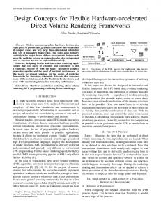
The joint specification, design and synthesis of mixed hardware/software systems, also called codesign, is a recent development issue. The interest in codesign is driven by increasing complexity and the need for early prototypes to validate the specification and provide the customer with feedback during the design process [1] [2]. Codesign aims to produce an heterogeneous architecture of mixed hardware/software components that implements an initial specification. As shown in figure 1, a typical Rapid System Prototyping (RSP) Codesign flow starts with a system specification given in an existing language (such as SDL or StateChart) [3]. At this stage, the specification is composed of a set of interacting modules. The next step is partitioning. The partitioning process transforms a system level specification into an heterogeneous architecture composed of hardware and software modules. This model is generally called virtual prototype. The virtual prototype is a simulatable model of the system. The final step is prototyping. The prototyping or architecture mapping, produces an architecture that implements or emulates the initial specification. * On leave from the Federal University of Rio de Janeiro, under grant supported by CAPES/COFECUB, BRAZIL.
CARLOS VALDERRAMA, ADEL CHANGUEL AND AHMED JERRAYA
2
VIRTUAL PROTOTYPE
VHDL SYSTEM SPECIFICATION
PROTOTYPE
HW
PARTITIONING
COM C
SW
CODESIGN PROTOTYPING
Figure 1. RSP and codesign flows.
One of the main difficulties in having this full design flow working is the link between the two last steeps e.g. Virtual Prototyping and Prototyping. As it will be shown later, most existing codesign environments restricts the architectural model used in order to deal with these steps. The goal of this work is to develop a methodology for fast prototyping of highly modular and flexible electronic systems including both, software and hardware. The main contribution of this work is the ability to handle a wide range of architectures. We assume that hardware/software partitioning is already made. Of course, this assume that partitioning is made with a set of architectures in mind. This may be very useful in the case where the goal is to map a given function onto an existing architecture, where the communication is already fixed. In this case the communication model is abstracted as a library component. At this stage we start with a heterogeneous architecture composed of a set of distributed modules, represented in VHDL for hardware elements and in C for software elements, communicating through communication modules (located into a library of components). This work concentrates on the use of virtual prototype for both cosynthesis (mapping hardware and software modules onto an architectural platform) and cosimulation (that is the joint simulation of hardware and software components) into an unified environment. In the following section, we give a brief overview of existing codesign solutions and challenges. In section 2, we introduce the concept of the unified environment for cosimulation and cosynthesis. In section 3, we detail the modular and flexible architectural model. The section 4 describes the communication unit concept, the modular specification, and the unified model for cosimulation and cosynthesis. The above concepts will be clarified by a real example (in section 5). And finally, in section 6, we conclude with perspectives and directions of future work.
1.1.
Objectives
This work deal with the cosimulation and cosythesis starting from mixed C, VHDL descriptions. The goal of this work is to combine the cosimulation and cosynthesis into an unified
VIRTUAL PROTOTYPING FOR MODULAR AND FLEXIBLE HW/SW SYSTEMS
3
environment. The definition of a joint environment for cosynthesis and cosimulation posses the following challenges: 1. Communication between the HW and SW modules, 2. Coherence between the results of cosimulation and cosynthesis and 3. Support for multiple platforms aimed at cosimulation and cosynthesis. The first issue is essentially due to the following reasons: Mismatch in the HW/SW execution speeds, communication influenced by data dependencies and support for different protocols [4]. The second issue is coming from the fact that different environments are used for simulation and synthesis. In order to evaluate the HW, the cosimulation environment generally uses a cosimulation library that provides means for communication between the HW and the SW. On the other hand, the cosynthesis produces code and/or HW that will execute on a real architecture. If enough care is not taken, this could result in two different descriptions for cosimulation and cosynthesis. The third issue is imposed by the target architecture. In general, the codesign is the mapping of a system specification onto a HW-SW platform that includes a processor to execute the SW and a set of ASIC’s to realize the HW. In such a platform (ex. a standard PC with an extended FPGA card), the communication model is generally fixed. Of course, the goal is to be able to support as many different platforms as possible. This paper presents a flexible modelling strategy allowing to deal with the three above mentioned problems. The general model allows to separate the behavior of the modules (hardware and software) and the communication units. Inter-modules interaction is abstracted using communication primitives that hide the implementation details of the communication units. 1.2.
Related Work
Several researchers have described frameworks and methodologies for codesign [2] [5] [6] [7] [8] [9]. Codesign environments differ by the way in which the Hw/Sw are described, abstraction level and communication model used. Most of the previous work have been targeted towards either cosimulation or cosynthesis and very few of them tried to combine both. However, they do not address all the three problems mentioned in the previous section, especially that of supporting multiple platforms. Codesign environments differs by the way in which the initial specification is described, synthesized, and the partitioned descriptions are evaluated. In the VULCAN cosynthesis system, the input language is HardwareC and the design system tries to gradually move hardware to software [10]. The Cosyma cosynthesis system (cosynthesis for embedded architectures) also starts with a single specification of the system given in C x (a super-set of the ANSI C standard). The approach is software-oriented, and the input specification is translated into an internal graph representation suitable for partitioning [11]. These
4
CARLOS VALDERRAMA, ADEL CHANGUEL AND AHMED JERRAYA
codesign tools needs to be linked to a rapid system prototyping environment including both cosimulation and cosynthesis. Condesign environments also differs by the way in which they handle cosimulation and cosynthesis. Different methodologies have been applied to cosimulation, cosynthesis and codesign platforms [8] [4] [12] [13] [14] [15]. Most of the previous work have been target either cosimulation or cosynthesis and very few of them tried to combine both [8] [13] [14]. A multi-paradigm simulation environment (Ptolemy), described in [6], supports cosimulation of different domains and a variety of hardware-software cosimulation techniques. In Ptolemy, the design process starts from a single specification, and the simulation is performed on the mixed Hw/Sw description obtained after partitioning. The tool presents a nice approach to deal with coherence between co-simulation/co-synthesis and support for multiple platforms, but it uses a restricted class of architectures. Communication between hardware and software is one of the main issues when dealing with cosimulation and cosynthesis. Some approaches make use of a fixed communication scheme depending on a fixed architectural platform [1] [7] [13] [9], in which case the first two problems addressed earlier are easily handled. Although some of these architectures are flexible (e.g. supports a variable number of hardware and software processors) they use a fixed communication model to exchange information between protocols [10] [16] [11]. The COSYMA system makes use of a model of the Sw processor for Hw/Sw communication. In this manner, COSYMA ensures coherence between cosimulation and cosynthesis and provides estimation of performances. The VULCAN system also uses a processor model for the software component [10]. Therefore it provides a very accurate simulation. In [17], hardware and software descriptions are treated as separate Unix processes which communicate through BSD (Berkeley Software Distribution) sockets. Since its targeting a specific application, it uses a fixed communication model between the hardware and software. A similar approach is described in [7]. The tool assists in mapping a specification onto a single processor with multiple ASICs. Software executes on the development processor and communicates with a hardware simulator through Unix inter-process communication mechanisms, using message passing. The COBRA project uses a prototyping environment based on a fixed architecture [16]. The project makes use of a FPGA based prototyping board called SPARROW. Therefore, it supports standard processor integration under real-time conditions as well as processor emulation. A more general approach for codesign, described in [11], performs simulation of Hw/Sw system at various stages of the codesign process. The methodology maintains two separate descriptions for Hw and Sw through the entire codesign process and communication is modelled as a message passing system. Communication primitives are inserted into the Hw/Sw descriptions to model the system communication. Using this model allows the communication between the Hw and Sw processes to take place without knowledge of the explicit details of the underlying bus interface. To handle the interaction between the Hw and Sw, four data transfer primitives are used. These primitives are inserted into the Hw and Sw descriptions to model the system communication. Although this approach increases the range of supported architectures (by working at a higher abstraction level of communication), the Hw/Sw cosimulation interface is implemented in terms of the supported communication modes. This approach solves the three challenges explained
VIRTUAL PROTOTYPING FOR MODULAR AND FLEXIBLE HW/SW SYSTEMS
5
above, but the user can not use communication modes other than the pre-defined or just existing communication modules.
2.
Methodology
The proposed methodology starts from a heterogeneous description composed of three parts: HW components described in VHDL, SW components as C programs, and communication component(s) to connect the above two parts (figure 2). The communication components, located into HW (VHDL) and SW (C) libraries, help to hide the possibly complex behavior of an existing platform. This methodology enables the user to profit from a wide range of communication schemes, abstracted by communication components and each sub-system can be treated independently of the communication scheme. COSIMULATION
HW/SW ALGORITHMS C LIBRARY
C COMPILER
C
VHDL
(SW)
(HW)
VHDL LIBRARY
HW SYNTHESIS
COSYNTHESIS
(SW) BUS
SW
HW/SW
HW
PROCESSOR
COMMUNICATION
ASICS
ROM - I/O
CONTROL
FPGAS
(HW) BUS
Figure 2. Methodology.
This methodology combines the co-simulation and co-synthesis into a unified environment, supporting multiple platforms [19]. The first step is to validate the heterogeneous description using a HW/SW cosimulation. The validation is performed by simultaneous cosimulation of VHDL and C descriptions. We use a VHDL-based cosimulation environment for VHDL descriptions. In that case, a VHDL entity is used to connect a HW module with that of SW. The same description will be used for co-synthesis as well. Each module can be synthesized using the corresponding tool. Hardware (VHDL) components are treated by hardware
CARLOS VALDERRAMA, ADEL CHANGUEL AND AHMED JERRAYA
6
synthesis tools, while software (C) components are handled by available software compilers. High-level synthesis tools map HW components into ASIC’s or FPGA’s. Software compilers map SW components into processor, ROM and I/O. The communication units are placed into a library of components and are not synthesized. The modelling approach hides specific HW/SW implementation details and communication schemes, thus allowing the cosynthesis and cosimulation to start from the same description. System-level interaction is abstracted using communication primitives that hide the underlying communication protocol. Therefore, each sub-system can be treated independently of the communication scheme. This methodology enables the user to profit from a wide range of communication schemes. This will be introduced in the following section.
3.
Architectural Model
We use a modular and flexible architectural model. The general model, shown in figure 3a, is composed of three kind of components: software components (aimed to execute C programs), hardware components (implements the VHDL descriptions) and communication components. This model serves as a platform onto which a mixed hardware/software system is mapped. Communication modules come from a library, they correspond to existing communication models that may be as simple as a handshake or as complex as a layered network. The proposed architectural model is general enough to represent a large class of existing hardware software platforms. It allows different implementation of mixed hardware/software systems, distributed architectures and several communication models. As shown in figure 3b, a typical architecture will be composed of several hardware modules, several software modules and communication modules linking HW and/or SW modules.
MPROC
I/O
RAM
SW FPGA
HW
SW
FPGA
ASIC
HW
COM
a)
b)
SW Figure 3. Architectural Model: a) architectural model. b) HW/SW platform.
HW
ASIC
PLD
FPGA
RAM
COM
MPROC
COM
VIRTUAL PROTOTYPING FOR MODULAR AND FLEXIBLE HW/SW SYSTEMS 4.
7
Unified Model for Cosimulation and Cosynthesis
This section details the unified model used for cosimulation and cosynthesis. The communication unit concept will be introduced first, then modular specification of the design will be explained. Finally, it will be shown that the combination of these concepts to the availability of multiple views for communication primitives allows modular design and design re-use of existing sub-systems.
4.1.
The Communication Unit Concept
Communication between sub-systems is performed via communication units which acts as a communication server for processors [20]. A communication unit is an entity able to execute a communication scheme invoked through a procedure call mechanism. The communication unit provides a fixed set of communication primitives (also called communication procedures, methods or services) to control access to the desired communication scheme. The model is known as the remote procedure call (RPC) [5]. To communicate, a sub-system calls a primitive (for memory access or message sending for example) as an ordinary procedure call. The communication unit unpacks the parameters, and send a reply back to the caller. In other words, the communication unit acts as a co-processor (or server). Communication procedures, that correspond to the visible part of the communication unit, hide the communication protocol. The rest is completely transparent to the user and contains ports linking the method parameters to the controller. The communication unit can include a controller which guards its current state as well as conflict-resolution functions. The complexity of the controller may range from a simple handshake protocol to as complex as a layered protocol. The procedures interact with the controller which in turn modifies the unit’s global state and synchronizes the communication. The communication modules are used as black boxes. The decision to make them in Hw or Sw is a partitioning decision that should be made before cosimulation. The figure 4a shows an abstract view of a communication unit linking two processes (UnitI and UnitII). Each process can be designed independently of one another. In this conceptual view, the communication unit is an object that can execute one or several procedures (get and put) that may share some common resource(s) (communication controller). This model hides all implementation details of the communication protocol. figure 4b shows a possible implementation of figure 4a. All the procedure calls are expanded according to the protocol selected. Each module will include an interface that control data exchange with communication controllers. The communication unit is a flexible communication model that allows to model most system level properties such as message passing, shared resources, and other more complex protocols (as Communication Networks). This mechanism allows design re-use, because, a communication unit may correspond to either an existing communication platform, or a design produced by external tools, or to a subsystem resulting from an early design session. This concept is similar to the concept of system function library in programming languages.
CARLOS VALDERRAMA, ADEL CHANGUEL AND AHMED JERRAYA CLK
COMMUNICATION CONTROLLER
a)
b)
UNIT II
DATAIN
RDY
B_FULL
INQUIRE
DATAOUT
P U T REQACK
GET
P U T
REQIN
PUT
UNIT I
SVRRESTART
UNIT II
G E T
RESTART
UNIT I
RESTART
G E T
INQACK
8
REQUEST-MANAGER COMMUNICATION CONTROLLER
Figure 4. The communication unit concept: a) conceptual view, b) implementation view.
4.2.
Modular Specification
The basic idea behind this work is to allow for modular specification of the design [21]. The communication scheme is described separately from the rest of the system. The use of procedures allows to hide the details related to the communication unit. All accesses to the interface of the communication unit is made through these procedures. The procedures fix the protocol of exchanging parameters between the sub-systems and the communication unit. This kind of model is very common in the field of telecommunication [22]. In this model, a communication network is hidded by the communication primitives. The network may be generated automatically by the partitioning step or given by the designer. The figure 5 shows a process that performs internal computations and exchange data with the external world. The process can be described as a FSM or made up of straight-line code segments [23]. Communication is done by using two communication procedures get and put. A call to the put or get procedure indicates an interaction with another process to perform an input (get) or output (put) operation. In spite of the FSM-oriented form of description used within the environment, the style do not alter the interaction performed by the communication procedures. As we can see, the only information necessary to perform the desired communication scheme is the fact that we can execute two methods named get and put. The rest of the channel is completely transparent to the user. We may have several protocols executing the same method. The communication between the sub-systems may be executed by one of the schemes (synchronous, asynchronous; serial, parallel) described in the library of communication units. The choice of a given communication unit will not only depend on the communication to be executed, but also on the performances required and the implementation technology.
VIRTUAL PROTOTYPING FOR MODULAR AND FLEXIBLE HW/SW SYSTEMS
9
INITIAL NEXTRECEIVE:= 0;
GET ( TEMP); WAITDATA
HOST PROCESS (FSM) TEMP /= NEXTRECEIVE NOACKDATA PUT ( NACK);
TRUE
FALSE ACKDATA NEXTRECEIVE:= (NEXTRECEIVE + 1); PUT ( ACK);
COMMUNICATION PROCEDURES PUT(DATA) GET(DATA)
Figure 5. Access to the interface of a communication procedure.
4.3.
Multiple Views for Communication Primitives
The use of modular description scheme, allows for separate evolution of the different modules. During the design process, several representations of the same object may be used at different design steps. During virtual prototyping, the modules are described at the behavioral level and the communication units are modelled as hardware or software processes. Later, after implementation, the communication units correspond to existing units. In order to allow the use of a communication unit at different design steps we need to describe its communication procedures into different views. Additionally, in order to be able to connect a communication unit to both, HW and SW modules, we have HW and SW views of a communication procedure. To support different applications, the number and type of views for each procedure will depend also on the co-simulation and co-synthesis environments used. The HW view (given in VHDL) may be common to both co-simulation and co-synthesis. In the case where we use different synthesis systems supporting different abstraction levels (e.g. a behavioral synthesis and an RTL synthesis), we may need different views for the communication procedures. figure 6 gives a hardware view for the procedure put for message passing based protocol. The procedure describes the interaction of the communication primitive with the controller by using internal signals and handshakes. This VHDL procedure, at the behavioral level, uses a FSM model to describe its interaction through the interface signals. Within the put procedure, specific commands (like ENABLE PUT, REQ PUT, or NOTREQ PUT) or single signal assignment operations performs this interaction. The figure 7 shows different software views of the communication procedure put. The two SW views are needed for co-simulation and co-synthesis respectively. The software simulation view (used for simulation) hides the simulation environment. In the present version, we use the Synopsys C-language Interface (CLI) as the target architecture for simulation, then the procedure is expanded into CLI routines [24]. Of
CARLOS VALDERRAMA, ADEL CHANGUEL AND AHMED JERRAYA
10
COMMUNICATION PROCEDURES
HOST PROCESS
GET(DATA)
(FSM)
PUT(DATA) PROCEDURE PUT (REQUEST: INTEGER) IS BEGIN CASE NEXT_STATE IS WHEN INIT =>ENABLE_PUT(B_FULL); IF B_FULL = '1' THEN NEXT_STATE:= INIT; ELSE NEXT_STATE:= DATA_RDY; END IF; WHEN DATA_RDY => REQ_PUT(RDY,REQUEST);
INTERFACE SIGNALS
IF RDY= '1' THEN NEXT_STATE:= CLOSE; END IF; WHEN CLOSE => NOTREQ_PUT(RDY); IF RDY = '0' THEN NEXT_STATE:= IDLE; END IF; WHEN OTHERS => NEXTSTATE:= INIT; END CASE; IF NEXTSTATE = IDLE THEN DONE:= '1'; ELSE NEXTSTATE = INIT; DONE:= '0'; END IF; END PROCEDURE;
Figure 6. Hardware view (VHDL) of a communication procedure.
course, other co-simulation models can be used. For example, if we use the Inter-processes Communication (IPC) model of UNIX , this communication procedure call will be expanded to system routines using the IPC mechanism. SW SIMULATION VIEW (CLI)
SW SYNTHESIS VIEW (IBM/PC)
• HIDES THE SIMULATOR COMMUNICATION DETAILS
• HIDES THE ARCHITECTURE COMMUNICATION DETAILS
INT PUT(REQUEST) INTEGER REQUEST; { SWITCH( NEXT_STATE ) { CASE INIT : { /* INIT STATE STATEMENTS */ } BREAK; CASE DATA_RDY : { CLIOUTPUT(DATAIN,REQUEST); CLIOUTPUT(REQ,BIT_1); IF( CLIGETPORTVALUE(RDY) == BIT_1) NEXT_STATE = CLOSE; } BREAK; CASE CLOSE :{ /* CLOSE STATE STATEMENTS */ } BREAK; DEFAULT : NEXTSTATE := INIT; } IF( NEXTSTATE == IDLE ) RETURN 1;
INT PUT(REQUEST) INTEGER REQUEST; { SWITCH( NEXT_STATE ) { CASE INIT : { /* INIT STATE STATEMENTS */ } BREAK; CASE DATA_RDY : { OUTPORT(DATAIN,REQUEST); OUTPORT(REQ,BIT_1); IF( INPORT(RDY) == BIT_1) NEXT_STATE = CLOSE; } BREAK; CASE CLOSE :{ /* CLOSE STATE STATEMENTS */ } BREAK; DEFAULT : NEXTSTATE := INIT; } IF( NEXTSTATE == IDLE ) RETURN 1; ELSE { NEXTSTATE == INIT; RETURN 0; } }
ELSE { NEXTSTATE == INIT; RETURN 0; } }
Figure 7. Different software views of a communication procedure.
The software synthesis view (used for synthesis) hides the compilation environment. The view will depend on target architecture selected. If the communication is entirely a software executing on a given operating system, communication procedure calls are expanded into system calls, making use of existing communication mechanisms available
VIRTUAL PROTOTYPING FOR MODULAR AND FLEXIBLE HW/SW SYSTEMS
11
within the system. For example, if the communication is to be executed on a standard processor, the call becomes an access to a bus routine written as an assembler code. In the example, the software synthesis view makes use of existing mechanisms available within the IBM/PC system. The communication can also be executed as an embedded software on a hardware data path controlled by a micro-coded controller, in which case, this communication procedure call will become a call to a standard micro-code routine. In this case, we need one HW view given in VHDL, one SW simulation view given in C, and a SW synthesis view specific to each target architecture. The difficulty found with the use of multiple views of a communication primitive is the management of the different views to support multiples applications and platforms within the environment. We assume the existence of trusted librarian able to produce coherent views. This is a general problem that exist when libraries are used. The librarian may be an automatic generation tool or a designer.
5.
An Example
This approach has been used for modelling an Adaptive Motor Speed Controller system. The system adjusts the position and speed parameters of a set of motors (to avoid discontinuous operation problems). For example, the control in a 2-D space needs one motor for each axis (X and Y) and an associated control system for a continuous movement. The system can handle up to 18 motors. However, in order to simplify the presentation, we will explain a single motor application. As shown in figure 8, the controller is composed of two sub-systems, Distribution and Speed Control, communicating through a communication channel.
USER INTERFACE PARAMETERS
MOTOR CONTROL SIGNALS
COORDINATES FEED-BACK DISTRIBUTION SUB-SYSTEM POSITION/MOTOR COORDINATES
COMMUNICATION CHANNEL
SPEED CONTROL SUB-SYSTEM SPEED COORDINATES
FEED-BACK
Figure 8. Adaptive motor controller system.
The Distribution sub-system provides the travelling distance to the Speed Control subsystem. With the specified position and the current state of the motor, the Speed Control sub-system computes the needed speed of the motor and send modulated pulses as motor control signals.
CARLOS VALDERRAMA, ADEL CHANGUEL AND AHMED JERRAYA
12
The system is partitioned into communicating HW/SW sub-systems and associated communication units (figure 9). The Distribution sub-system is described by a software abstract model and the Speed Control sub-system by a hardware abstract model. In the early stage of the design, the motor is modelled as a hardware processor. The communication between the Speed Control sub-system (software) and the Distributor sub-system (hardware) is described using a communication unit composed of two groups of access procedures (Distribution Interface and Control Interface). The communication between the Speed Control sub-system and the motor (modelled as a HW process) is achieved by a communication unit (accessed by a collection of procedures called Motor Interface). The use of the above communication units enables the description of the sub-systems independent of the architectural platform that may be chosen. SOFTWARE
HARDWARE
DISTRIBUTION SUB-SYSTEM ABSTRACT MODEL
SPEED CONTROL SUB-SYSTEM ABSTRACT MODEL
DISTRIBUTION_INTERFACE ACCESS PROCEDURES
CONTROL_INTERFACE ACCESS PROCEDURES
MOTOR ABSTRACT MODEL MOTOR_INTERFACE ACCESS PROCEDURES
SOFTWARE COMMUNICATION CONTROLLER
HARDWARE
COM. UNIT
COM. UNIT
COMMUNICATION CONTROLLER
Figure 9. The adaptive motor controller: virtual prototype.
The Distribution sub-system is a software model. figure 10a shows its main computation steps and the main communication primitives used by this subsystem. It activates the Speed Control sub-system of the motor by specifying the maximum position value and the maximum number of speed-pulses. INT DISTRIBUTION()
COMPUTE
{ DONE = 1;
COMMUNICATION PRIMITIVE
DISTRIBUTION_INTERFACE COMMUNICATION PROCEDURES : * SETUPCONTROL * MOTORPOSITION * READMOTORSTATE
STATE
START
TEST
LOADMOTORCONSTRAINTS
BUS
SWITCH( NEXTSTATE ) { CASE START: { /*LOADMOTORCONTRAINTS*/ NEXTSTATE=SETUPCONTROLCALL; } BREAK; CASE SETUPCONTROLCALL: { IF ( SETUPCONTROL() ){ NEXTSTATE=STEP; } } BREAK;
DISTRIBUTION SUB-SYSTEM
SETUPCONTROL
CASE STEP: { /*POSITIONDEFINITION*/
UPDATEPOSITION
STEP
NEXTSTATE=MOTORPOSITIONCALL; } BREAK; CASE MOTORPOSITIONCALL:
POSITIONDEFINITION
{ IF( MOTORPOSITION(POSITION) ) { NEXTSTATE=NEXT; } } BREAK;
READMOTORSTATE
/*OTHER "CASE" STATEMENTS*/ DEFAULT: MOTORPOSITION
NEXT
A)
NEXTSTEP
{ NEXTSTATE=STARTS; } }
B)
RETURN DONE; }
Figure 10. Distribution sub-system.
The total translation distance of the motor is divided into segments and is sent to the Speed Control sub-system as bundles of data. The initialization data, motor selection
VIRTUAL PROTOTYPING FOR MODULAR AND FLEXIBLE HW/SW SYSTEMS
13
and position co-ordinates are transmitted to the Speed Control sub-system by the Distribution Interface access procedures (SetupControl, MotorPosition, and ReadMotorState) which communicate through the I/O interface. The figure 10b shows an extract of the C code corresponding to the Distribution Subsystem. In this case, the code is organized as a finite state machine composed of states, transitions, and calls of communication procedures. The Speed Control sub-system is described by a hardware abstract model in VHDL (figure 11). This sub-system uses communication procedures, which are described in VHDL. The sub-system is composed of three parallel processes named: Position, Core and Timer. The Position process actualizes motor position and co-ordinates. It communicates with the Distributionsub-system using the Control Interface access procedures by sending the actual motor state (via ReturnMotorState access procedure) and waiting for the new co-ordinates and motor constraint parameters (ReadMotorConstraints and ReadMotorPosition access procedures). The Core process computes the residual position and the next operation conditions. It communicates with the two other units using simple VHDL signals. The Timer process sends a set of motor control pulses to the motor and reads the motor co-ordinates using the Motor Interface access procedures (SendMotorPulses and ReadSampledData). MOTOR SIGNALS
BUS
SPEEDCONTROL_INTERFACE COMMUNICATION PROCEDURES : * READMOTORCONSTRAINTS * READMOTORPOSITION * RETURNMOTORSTATE -- POSITION UNIT : PROCESS BEGIN IF NOTSTARTUP THEN READMOTORCONSTRAINTS READMOTORPOSITION END IF ; IF ENDPOSITION THEN RETURNMOTORSTATE READMOTORPOSITION END IF ; END PROCESS ;
SPEED CONTROL SUB-SYSTEM -- CORE UNIT : PROCESS BEGIN READSAMPLEDDATA MOTORVARIABLES : --COMPUTEDIRECTION --COMPUTESPEED --COMPUTEASCELERATION --COMPUTERESIDUALPOSITION END PROCESS ;
MOTOR_INTERFACE COMMUNICATION PROCEDURES : * READSAMPLEDDATA * SENDMOTORPULSES
-- TIMER UNIT : PROCESS BEGIN --COMPUTEPULSEWIDE SENDMOTORPULSES --COMPUTEDESVIATION END PROCESS ;
Figure 11. Speed control system (VHDL).
We simulated the system at two different abstraction levels. The entire system was simulated first at the behavioral level to verify functionality. After Hw synthesis, a second cosimulation was performed in order to verify timing constraints. For this purpose, we used a distributed co-simulation environment, composed of a VHDL simulator for hardware modules and C-debuggers for software modules (C-programs) communicating via a software bus. This software bus relies on the Unix IPC layer. The software bus and the elements used to interface VHDL and C modules during simulation where automatically created by a VHDL-C interface generation tool (named VCI) [23] [25]. The system was described as a VHDL structure to allow the interconnection of Hw and Sw parts. The Sw subsystem (a C-program executed on the workstation) was interconnected to the Hw part
14
CARLOS VALDERRAMA, ADEL CHANGUEL AND AHMED JERRAYA
by using the Sw simulation view of its communication procedures. For simulation purpose these communication procedures were associated to cosimulation primitives making use of the Unix/IPC mechanism. The Hw part was simulated within the VHDL simulator. The results of cosimulation are the waveforms generated by the VHDL simulator and the C-program execution. During the debug phase, we can execute the C-program and the VHDL simulator step by step in order to follow the execution. figure 12 is a screen capture showing a simple cosimulation session consisting of the execution of the C-program (left-side) and the VHDL simulation of the Hw part (right-side).
Sw
Hw
Figure 12. Motor controller cosimulation test-bench.
After co-simulation, the co-synthesis was made using an existing platform. In this example we used an architecture composed of a PC-AT communicating with an FPGA based board via the extension bus of the PC. The communication primitives have been selected based on the target architecture. The software primitives correspond to C procedures that makes use of specific system calls (I/O routines) requiring some physical addresses. The communication primitives used by the hardware side are written in order to respect the timing and the protocol considerations required by the PC and the motor signals. As shown in figure 13, the Distribution sub-system (a C program) was compiled on a 386-based processor which communicates with an FPGA development board (the Speed Control sub-system) through a 16-bit parallel bus (synchronous communication, 10 MHz). The Speed Control sub-system was synthesized onto a Xilinx 4000-series FPGA, associated with memories (EPROM’s) and a microcomputer interface. An analysis of the prototype system indicates that this solution confirms the results obtained during cosimulation. The
VIRTUAL PROTOTYPING FOR MODULAR AND FLEXIBLE HW/SW SYSTEMS
15
implementation correctly implements the system functionality while meeting the real-time constraints. In order to map this application onto another target architecture, we need to have the corresponding communication primitives. One can note that the target architecture may be a complex multiprocessor architecture.
SPEED CONTROL COMPONENT FPGA
MOTOR HARDWARE PART
PC AT EXTENSION BUS
SYSTEM MEMORY EPROM RAM
MICROPROCESSOR
SOFTWARE PART
Figure 13. The adaptive motor controller system prototype.
6.
Conclusion
This paper presented a virtual prototyping strategy for co-design based of mixed C, VHDL specifications. The same descriptions can be used for both cosimulation and cosynthesis. It also allows to accommodate several architectural models through the use of a library of communication models enabling the abstraction of existing communication schemes and design re-use. In other words, the same module descriptions are usable with different architectures in terms of their underlying communication protocols. Acknowledgments This work is sponsored by France Telecom, Aerospatiale and SGS-Thomson. References 1. R.K.Gupta, G.DeMicheli, “System-level Synthesis using Re-programmable Components,” Proc.Third European Conf. Design Automation, IEEE CS Press, pp.2-7, 1992. 2. D.Gajski, F.Vahid, “Specification and Design of Embedded Hardware-Software Systems,” IEEE Design & Test of Computers, pp. 53-67, Spring 1995. 3. T.BenIsmail, A.A.Jerraya, “Synthesis Steps And Design Models For Codesign,” IEEE Computer, pp.44-52, February 1995.
16
CARLOS VALDERRAMA, ADEL CHANGUEL AND AHMED JERRAYA
4. K.Ten Hagen, H.Meyer, “Timed and Untimed Hardware/ Software Cosimulation: Application and Efficient Implementation,” International Workshop on Hardware-Software Codesign, Cambridge, October 1993. 5. T.BenIsmail, M.Abid, K.O’Brien, A.A.Jerraya, “An Approach for Hardware-Software Codesign,” RSP’94, Grenoble, France, June 1994. 6. A.Kalavade, E.A.Lee, “A Hardware-Software Codesign Methodology for DSP Applications,”IEEE Design and Test of Computers, pp.16-28, September 1993. 7. D.E.Thomas, J.K.Adams, H.Schmit, “A Model and Methodology for Hardware-Software Codesign,” IEEE Design & Test of Computers, Vol.10, N3, pp.6-15, September 1993. 8. H.Fleukers, J.A.Jess, “ESCAPE: A Flexible Design and Simulation Environment,” Proc. of The Synthesis and Simulation Meeting and International Interchange, SASIMI’93, pp.277-288, Oct.1993. 9. E.A.Walkup, G.Boriello, “Automatic Synthesis of Device Drivers for Hardware/Software Co-design,” International Workshop on Hardware-Software Codesign, Cambridge, October 1993. 10. R.K.Gupta, C.N.Coelho, G.DeMicheli, “Synthesis and Simulation of Digital Systems Containing Interacting Hardware and Software Components,” Proc. 29th Design Automation Conf. ACM/IEEE CS Press, pp. 225234, 1992. 11. R.Ernst, J.Henkel, T.Benner, “Hardware-Software Cosynthesis for Microcontrollers,” IEEE Design & Test of Computers, vol.10, N4, pp.64-75, December 1993. 12. W.M.Loucks, B.J.Doray, D.G.Agnew, “Experiences In Real Time Hardware-Software Cosimulation,” Proc VHDL Int. Users Forum (VIUF), Ottawa, Canada, pp.47-57, April 1993. 13. S.Lee, J.M.Rabaey, “A Hardware Software Cosimulation Environment,”International Workshop on Hardware-Software Codesign, Cambridge, October 1993. 14. N.L. Rethman, P.A.Wilsey, “RAPID: A Tool For Hardware/ Software Tradeoff Analysis,” Proc. CHDL’93, Otawa, Canada, April 1993. 15. P.Camurati, F.Corno, P.Prinetto, C.Bayol, B.Soulas, “System-Level Modelling and Verification: a Comprehensive Design Methodology,” Proc. of EDAC-ETC-EuroASIC’94, Paris, February 1994. 16. G.Koch, U.Kebshull, W.Rosenstiel, “A Prototyping Environment for Hardware/Software Codesign in the COBRA Project,” Proc.Third International Workshop HW/SW Codesign, Grenoble, France, pp. 10-16, Sept. 1994. 17. D.Becker, R.Singh, S.Tell, “An Engineering Environment for Hardware/Software Cosimulation,” Proc. Design Automation Conference ACM, pp.129-134, 1992. 18. S.L.Coumeri, D.E.Thomas, “A Simulation Environment For Hardware-Software Codesign,” Proc. ICCD Conf., IEEE CS Press, October 1995. 19. C.Valderrama, A.Changuel, P.V.Raghavan, M.Abid, T.B.Ismail, A.A.Jerraya, “A unified model for cosimulation and co-synthesis of Mixed Hardware/Software systems,” The European Design and Test Confrence ED&TC95 Paris,France, March 1995. 20. K.O’Brien, T.B.Ismail, A.A.Jerraya, “A Flexible Communication Modelling Paradigm for System-level Synthesis,” International Workshop on Hardware-Software Codesign, Cambridge, October 1993. 21. D.Ungar, R.B.Smith, C.Chambers, U.Holzle, “Object, Message, and Performance: How They Coexist in Self,” IEEE Computer, October1992. 22. G.V.Bochmann, “Specification Languages for CommunicationProtocols,” Proc. CHDL’93, Ottawa, Canada, April 1993. 23. P.Paulin, J.Frehel, E.Berrebi, C.Liem, J-C Herluison, M.Harrand, “High-level Synthesis and Codesign Methods: An Appication to a Video phone Codec,” Invited Paper EuroDAC/VHDL, Bringhton, September 1995. 24. “Synopsys VHDL System Simulator Interfaces Manual: C-language Interface,” Synopsys Inc., Version 3.0b, June 1993. 25. C.A.Valderrama, F.Nacabal, P.Paulin, A.A.Jerraya, Automatic Generation of Interfaces for Distributed CVHDL Cosimulation of Embedded Systems: an Industrial Experience ,to appear in RSP’96, 7th IEEE International Workshop on Rapid Systems Prototyping, 19-21 June, Thessaloniki, Greece, 1996.
Received Date Accepted Date Final Manuscript Date
Table of Contents: Volume ()
Number ? Virtual Prototyping For Modular And Flexible Hardware-Software Systems . : : : : : : : : : : : : : : : : : : : : : Carlos A.Valderrama, Adel Changuel And Ahmed A.Jerraya
275
Design Automation For Embedded Systems Volume , No. , Virtual Prototyping For Modular And Flexible Hardware-Software Systems . : : : : : : 275 : : : : : : : : : : : : : : : : : : : : : Carlos A.Valderrama, Adel Changuel And Ahmed A.Jerraya