Virtual Range Scan for Avoiding 3D Obstacles Using 2D Tools Stefan Stiene* and Joachim Hertzberg Institute of Computer Science, Knowledge-Based Systems Research Group University of Osnabr¨uck Albrechtstraße 28, D-49069 Osnabr¨uck, Germany
[email protected]
Abstract— This paper presents a new method for seamless fusion of arbitrary range sensors for mobile robot obstacle avoidance. This method, named Virtual Range Scan (VRS), is able to deal with arbitrary sensor configurations (2D and 3D) and it is independent of the underlying obstacle avoidance strategy. This makes it a very flexible approach that can reuse existing 2D obstacle avoidance algorithms for 3D obstacle avoidance. Additionally the VRS is able to keep obstacles in memory in order to incorporate them even if they are no longer visible in the current real sensor data. To combine this memory effect with the presence of dynamic objects in the robot surroundings, a motion tracker is used. We demonstrate the ability of the VRS to realize 3D obstacle avoidance using two different sensor configurations for taking 3D range data and classical two dimensional obstacle avoidance methods.
I. I NTRODUCTION Obstacle avoidance is one of the key requirements an autonomous mobile robot has to fulfill. Especially in a working environment shared by humans and robots, secure obstacle avoidance is an absolute precondition to ensure the humans’ safety. In mobile robotics, obstacle avoidance is realized as reactive adaptation of the robot’s motion commands with respect to sensor information about its surroundings. In contrast to path planning, which ensures the global collision-free navigation to a given goal, obstacle avoidance is a local problem and does not require a global representation of the environment. Strategies and sensors for achieving collision-free navigation exist in considerable variety. In this paper we address the problem that most of these strategies and corresponding sensor configurations only consider two dimensions [9], which is insufficient in real, cluttered, dynamic working environments. A precondition for safe navigation in a three dimensional environment is that the sensor configuration is able to detect obstacles all over the robot’s bounding box. This paper presents a method for fusing range data, which may regard 3D information, and handling them by means of available 2D tools. In consequence, 3D obstacle avoidance is achieved in a compuationally cheap way that integrates *Financial support for this research and development project LiSA is provided by the German Federal Ministry for Education and Research (BMBF) as part of the framework program ”Forschung f¨ur die Produktion von Morgen” (Research for tomorrow’s production; grants no. 02PB217002PB2177). Its administration is handled by the Project Management Agency Forschungszentrum Karlsruhe (PTKAPFT).
standard 2D appoaches in a uniform way. The method is demonstrated for two different sensor configurations that include components for taking 3D data. The next section points to related work concerning 3D obstacle avoidance. Section III describes our approach for fusing range senors. Section IV gives several experiments showing the ability of the VRS concept to enable 3D obstacle avoidance using 2D avoidance strategies. The paper concludes in section V with an outlook on future work. II. R ELATED W ORK There are two different approaches to achieve three dimensional obstacle avoidance. The first approach considers the whole three dimensional space and computes optimal motion commands in all six degrees of freedom [12]. Hence these algorithms are suited for autonomous flying robots or underwater robots. The drawback of these algorithms is that they suffer from high computational complexity. Since wheeled mobile robot motion is often restricted to a two dimensional plane, the second approach maps the three dimensional sensor data onto a two dimensional data set. In [3] a permanently tilting laser scanner is used to be aware of the 3D workspace in front of the robot. The points obtained by the scanner are stored in a robot-centric representation equivalent to that of an ordinary 2D laser scan. This data set includes the relevant information for obstacle avoidance algorithms. In [13] a permanently rotating laser scanner is used. The scanners orientation result in a vertical 2D scan and the rotation around the upright axis produce a 360◦ field of view. For obstacle avoidance the nearest point of each 2D scan is integrated into a virtual scan which is used for obstacle avoidance. The main drawback of this approach and the approach presented in [3] is, that the methods only work with a special sensor configuration. Additionally the used sensor configuration of a tilting or rotating laser scanner does not provide a permanent obstacle avoidance in 3D. In contrast the VRS concept presented in this paper can deal with arbitrary sensor configurations, has an obstacle memory and is aware of dynamic objects in the robot surrounding. Stanley, the robot that won the DARPA Grand Challenge uses 5 laser scanners mounted on the roof of the robot, tilted downward to scan the road [10]. They overlay the 3D point
cloud obtained by the laser scanners while driving with a 2D grid map. Using a probabilistic method that tests for sudden changes in the height coordinate for all 3D points within a cell of the grid map, the cell is marked as free or occupied. Afterwards, navigable space is identified by fitting a quadrilateral ahead of the robot in the 2D grid map. Dynamic objects are ignored since the system was developed for a desert environment. Beside sensor configurations using laser scanners, two camera based methods are widely-used. The first one uses a single camera to detect obstacles in 3D using the optical flow [2]. The second technique triangulates two cameras to get the 3D information of the environment. In [7] this stereo vision technique is combined with horizontally mounted 2D laser scanners to achieve collision-free navigation. The drawback of these methods is a relatively high computational load. Moreover they tend to fail if obstacles are insufficiently textured. III. T HE V IRTUAL R ANGE S CAN C ONCEPT The virtual range scan (VRS) combines sensor data from arbitrary range sensors into a virtual two dimensional data set. The reason to do this is, that projecting available 3D information in a 2D frame allows us to use simple, efficient, and widespread tools for robot control (player [11], in our case, see below), yet react correctly to avoid obstacles in 3D, based on the recent sensor data. Using the robot center point as the common point of reference, each range value can be transformed to a point in three dimensional space. These 3D points can be integrated into the VRS in two ways: direct and memory based integration. For both forms of integration, the two dimensional horizontal plane is subdivided into polar segments with a robot centered origin. We are using an angular resolution of one degree. A 3D point is integrated into the VRS by projection onto the polar plane. The range value for each polar segment is the minimum distance from the origin to the points that were projected into this segment. The direct integration is used with horizontally mounted range sensors. Memory based integration keeps the 3D points in memory. This is required since obstacles may disappear from sensor view; for example, in the sensor configuration used here, static 3D objects will disappear from sight of the tilted scanners, as the robot moves along. To achieve the memory effect, the 3D points are projected onto a grid map with respect to the current robot pose obtained by Monte Carlo Localization. This transforms the generation of the VRS from a local to a global coordinate problem. The localization uncertainty has to be taken into account in the process, as discussed later. Fig. 1 shows how the grid map is integrated into the generation of the VRS. There are two laser scanners (red and grey beams) that are directly integrated into the VRS. Additionally, the polar segments (blue) are shown. The obstacle grid map is combined with the direct integrated points through a ray tracing in the grid map based on the current robot pose (magenta beams). In order to accelerate
Fig. 1. VRS with grid map as obstacle memory: The robot (light grey) is standing in front of a door (bold black lines are walls). Using ray tracing (magenta) in the obstacle grid map (gray squares) determines if the remembered obstacle has a shorter distance to the robot than all direct integrated sensors (red and grey). If this is the case, the range (green) for the segment (blue) is adapted to the ray tracing distance. In order to accelerate the ray tracing procedure, a maximum distance is defined (magenta circle). See text for additional explanation.
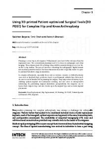
Fig. 2. Takes of the VRS data in the same scene. Left: VRS by direct integration taking only the most recent input of two horizontally mounted laser scanners as input. Right: VRS of the same scene after integration of the local obstacle map (black), resulting from memory based integration of non horizontally mounted range sensors and prior robot motion in the scene.
the ray tracing procedure, a maximum distance of obstacles that are integrated into the VRS is defined (magenta circle). If the distance obtained by the ray tracing procedure for a polar segment is shorter than the minimum distance of all direct integrated points, the polar segment’s range value is set to ray tracing distance. Fig. 2 (left) shows the VRS data using two direct integrated horizontally mounted laser scanners with a 270◦ field of view as input (cf. Fig. 1 red and grey). Since this VRS reflects the environmental boundaries, it is suitable for mobile robot localization. The right part shows the VRS after integration of the obstacle map generated by non horizontally mounted laser scanners. Since this VRS is aware of table tops and seat bases, it is suitable for 3D obstacle avoidance.
A. Filtering the Data Due to sensor and localization noise mentioned above, filters have to be used when integrating the 3D points into the obstacle grid map. Wrongly inserted points would cause the robot to hallucinate obstacles. In consequence, the following filters are used: 1) 3D points are omitted from integration into the obstacle grid map, if there are any directly integrated points closer to the robot for the respective polar segment. 2) 3D points higher than the robot’s maximal height are omitted. 3) 3D points are omitted, if their distance to the robot is above a defined threshold. The first filter is safe since there is no use for keeping in memory an obstacle that is already visible in the direct integrated sensors. The second filter make sense, since objects above robot height cannot cause harm. The third filter reduces the influence of any localization orientation error and is safe because of the obstacle’s distance. Among the issue of wrongly inserted 3D points, the handling of dynamic objects in the robot’s environment is a crucial part of the VRS. For example, a human walking around the robot would cause obstacles to be detected incorrectly all around the robot; the experiment that tests the different filters in the following section, shows the effect. These points cannot be filtered out by simple geometric filters. The problem can only be solved by discriminating between static and dynamic obstacles in the robot’s surroundings. Dynamic objects are detected by observing sudden changes in the directly integrated range sensors. The dynamic objects are tracked by a Kalman filter based motion tracker. Each moving object has an uncertainty ellipse representing the probability that a dynamic object is at this position. In order to omit all 3D points caused by dynamic objects from integration into the obstacle grid map, the points are projected onto the polar plane. If the projected points lie within a dynamic object’s uncertainty ellipse, the point is omitted. In our implementation, we have used the motion tracker provided in the “cure” framework [8]. The motion tracker also successfully takes the ego motion of the robot into account and compensates it. The motion filter together with the other three filters achieve that only 3D points caused by static obstacles that are not visible in the directly integrated sensors, like table tops or shelves, are integrated in the grid map. Additionally to all filters, an aging process is applied on the grid map to ensure that wrongly inserted obstacles do not block the robot forever. This aging process only continues if the robot moves; otherwise the robot could “forget” obstacles during a longer stop, like a manipulation task near a table. During the manipulation, the table edge is not visible in the sensor data. After the manipulation phase, the robot would collide with the table edge because the VRS and thus the obstacle avoidance algorithm would be unaware of it. In our implementation the threshold is 25 seconds of robot movement before it forgets an obstacle.
Fig. 3. Left: Schematic top view showing the laser scanner configuration. Right: Simulated LiSA robot with rendered laser scanner beams. The SICK laser scanners (blue beams) form a horizontal plane, the Hokuyo laser scanner planes (green beams) a funnel around the robot.
IV. E XPERIMENTS In this section we test the VRS concept with different 2D and 3D sensor configurations. One plattform we used is the LiSA robot (Fig.5, left). It is equipped with six laser scanners. Two SICK s300 scanners are mounted horizontally on opposite corners of the robot. Since both scanners have a field of view of 270◦, their combination provides a 360◦ field of view in a horizontal plane (see Fig. 3 blue rays). Since two dimensional sensor information is insufficient for collision free navigation in 3D, the sensor configuration is extended by four Hokuyo laser scanners. They are mounted just above base plane height and pointing upward at an angle so that all four laser scanners form a funnel around the robot (see Fig. 3, green rays). A. Testing the point filters The results of the 3D point filters for the local obstacle map are shown in Fig. 4. The red dots are the 3D points that are classified as obstacles and integrated into the obstacle map while the LiSA robot does a 360◦ turn and a human walks around the robot. In the left figure, all 3D points are integrated into the obstacle grid map. This leads to various incorrect inserted points and the robot is effectively
Fig. 4. 3D points integrated in the obstacle grid subject to the used filters. Left: No filter is applied on the 3D points. Obviously, the localization suffers from an orientation error here. Middle: Filters 1 and 2 are applied on the 3D points. Right: 3D points belonging to dynamic objects are deleted.
blocked. The middle figure shows the remaining 3D points after filters 1 and 2 are applied. It is obvious that many previously inserted points are removed. However the robot is still blocked due to the 3D points caused by the human walking around the robot. Fig. 4(right) shows the result of the additionally applied dynamic object filter that uses the kalman motion tracker. In fact, all removed points were caused by the human walking by. B. Testing the VRS for enabling 3D obstacle avoidance The ability of the VRS to enable 3D obstacle avoidance is tested using the LiSA robot’s 3D sensor configuration and a 3D camera based sensor configuration in combination with the two dimensional obstacle avoidance algorithms Vector Field Histogram (VFH [1]) and the Nearness Diagram (ND [6]) provided by the player framework [11]. Fig. 5 (left) shows a scene of the robot run. The crucial part of the parcours for all obstacle avoidance algorithms based on 2D data is the configuration of two chairs standing back-toback. The distance between the chair legs appears to offer enough space for the LiSA robot to pass through, so the path through the chairs is identified as navigable by 2D sensor configurations. Fig. 5 (right) shows this experiment. The ND algorithm is used with a VRS, supplied solely with the 2D SICK scanner data. As expected, the VRS only contains the chair legs and no seat bases. The ND method identifies the area as navigable, and the robot physically collides with the chairs. In the second experiment, the VRS uses the data from all six laser scanners as input. Fig. 6 shows the VRS and the robot path through the parcours resulting from the ND obstacle avoidance generated motion commands. The 3D information allows the chairs to be detected in the VRS. The ND algorithm identifies the chair region as not navigable and steers the robot round the chairs. C. Integrating a 3D Camera into the Virtual Range Scan This section demonstrates that other range sensors can be integrated seamlessly into the obstacle avoidance process with the VRS concept. In addition to the previously described sensor configuration, a time-of-flight PMD camera is used [5]. This sensor uses an array of laser diodes to assign a range value to each pixel. Using the camera pose and intrinsic
Fig. 7. Left: Unfiltered point cloud obtained during a 360◦ turn in an office environment. Right: Filtered point cloud. Sensor errors from reflection and range steps are removed.
parameters, each pixel represents a point in 3D space. Since the PMD camera does not provide RGB-color information, a normal camera is used together with it to assign a color value to each 3D point. Using colored points offers more robust sensor error filtering. Fig. 7 shows colored 3D points obtained by the sensor during a 360◦ turn in an office environment. Apparently, the sensor is able to map the 3D structure of the office environment. However, there are many sensor errors due to reflection on windows or so called flying pixels at range steps, which arise from integration errors in the sensor(left). These sensor errors have to be filtered out before the PMD data is integrated into the VRS. We have
Fig. 5. Left: Experimental setup that requires 3D environment awareness to identify the region below the chair seats as not navigable. Middle and Right: The VRS using only the two SICK laser scanner is not aware of the chair seats. The ND obstacle avoidance algorithm identifies the chair region as navigable and the robot collides with the chairs.
Fig. 6. The VRS integrates the information of all six laser scanners. Accordingly, the obstacle grid map contains the chair seats. The VRS marks the chair region as blocked and the ND algorithm navigates the robot around the chairs.
used the filtering method described by Huhle et al. [4]. It is a clustering algorithm in the spatial and color space that detects isolated points. Fig. 7 (right) shows the PMD camera data with isolated points removed. The filter removes nearly all sensor errors; note that it also removes a number of true positive data points. Since the only precondition of the VRS is, that an integrated sensor is able to map its sensor data onto 3D points, this sensor can be seamlessly integrated. Fig 8 presents the results of an experiment using a VRS combining a SICK laser scanner and the PMD camera. The sensors are mounted on a smaller robot to clarify that the VRS concept is not restricted to the LiSA robot’s sensor configuration. The left figure shows the experimental setup. The robot has to drive around two wastebins, which are not visible in the laser scanner data. The middle figure shows, that the VRS (blue) is aware of the obstacles due to the PMD camera’s sensor data (red points) and the ND obstacle avoidance navigates the robot around the wastebins (right). Space does not permit to present more experiments. The VRS has proven to perform robustly as expected. Some video
material about additional experiments is available at www. informatik.uos.de/kbs/lisa_downloads.html
D. Integrating Restricted Zones into the Virtual Range Scan The VRS makes it easy to integrate restricted zones for the robot. A restricted zone can be for example the area around a staircase heading down or other obstacles that can not be safely identified in the sensor data. The standard way to solve this problem is to use a high level path planner that takes the restricted zones into account in the global path. Using the VRS, there is an alternative. The restricted zone is directly integrated into the obstacle grid map. In consequence, the restricted zone is integrated together with the sensor data in the VRS. Hence the restricted zones look like real obstacles for a classical two dimensional obstacle avoidance algorithm. Fig. 9 presents the result of an experiment with a robot using a VRS with a forward directed SICK scanner and a backward directed Hokuyo scanner as input (top). The bottom figure shows, that the VRS is aware of the restricted zones and the robot navigates around them.
Fig. 8. Left: Experimental setup Middle: The VRS (blue) is aware of the obstacles due to the PMD camera (red points). Right: The robot navigates around the wastebins.
VI.
ACKNOWLEDGEMENT
Financial support for this research and development project LiSA is provided by the German Federal Ministry for Education and Research (BMBF) as part of the framework program ”Forschung f¨ur die Produktion von Morgen” (Research for tomorrow’s production; grants no. 02PB2170-02PB2177). Its administration is handled by the Project Management Agency Forschungszentrum Karlsruhe (PTKAPFT). R EFERENCES
Fig. 9. Top: Mobile robot equipped with forward directed SICK and backward directed Hokuyo scanner. Bottom: The VRS (blue) is aware of the restricted zones (magenta) and the robot navigates round them (red path).
V. C ONCLUSION
AND
F UTURE W ORK
This paper has presented the VRS concept. It combines range sensors in arbitrary configurations with classical two dimensional obstacle avoidance tools. Using two different 3D range sensor configurations as demonstrating examples, the VRS enables the robot to navigate in cluttered, dynamic environments. Future work will involve additional ranging sensors, like stereo cameras, sonars, and tilting / rotating laser scanners.
[1] J. Borenstein and Y. Koren. The vector field histogram-fast obstacle avoidance for mobile robots. IEEE Journal Of Robotics And Automation, 7(3):278–288, 1991. [2] C. Braillon, et al. Real-time moving obstacle detection using optical flow models. In Proc. IEEE Intelligent Vehicles Symposium, pages 466–471. 2006. [3] D. Holz, et al. Continuous 3D sensing for navigation and slam in cluttered and dynamic environments. In Proc. 11th Intl. Conf. Information Fusion (Fusion 2008). 2008. [4] B. Huhle, et al. On-the-fly scene acquisition with a handy multisensorsystem. In Dynamic 3D Imaging Workshop in Conjunction with DAGM 2007. September 2007. [5] R. Lange and P. Seitz. Solid-state time-of-flight range camera. IEEE Journal of Quantum Electronics, 37(3), March 2001. [6] J. Minguez and L. Montano. Nearness diagram navigation (ND): a new real time collision avoidance approach. In L. Montano, editor, Proc. IEEE/RSJ International Conference on Intelligent Robots and Systems (IROS 2000), volume 3, pages 2094–2100 vol.3. 2000. [7] A. Murarka, et al. Building Local Safety Maps for a Wheelchair Robot using Vision and Lasers. In Proc. of the The 3rd Canadian Conference on Computer and Robot Vision (CRV ’06), page 25. 2006. [8] E. Pacchierotti, et al. Evaluation of Passing Distance for Social Robots. In Proc. 15th IEEE International Symposium on Robot and Human Interactive Communication ROMAN 2006, pages 315–320. 2006. [9] R. Siegwart and I. Nourbakhsh. Introduction to Autonomous Mobile Robots. MIT Press, 2004. [10] S. Thrun, et al. Stanley: The Robot that won the DARPA Grand Challenge. J. Robot. Syst., 23(9):661–692, 2006. [11] R. Vaughan, et al. On device abstractions for portable, reusable robot code. In B. Gerkey, editor, Proc. IEEE/RSJ International Conference on Intelligent Robots and Systems (IROS 2003), volume 3, pages 2421– 2427 vol.3. 2003. [12] D. Vikenmark and J. Minguez. Reactive obstacle avoidance for mobile robots that operate in confined 3d workspaces. In J. Minguez, editor, Proc. IEEE Mediterranean Electrotechnical Conference MELECON 2006, pages 1246–1251. 2006. [13] O. Wulf, et al. 2D Mapping of Cluttered Indoor Environments by Means of 3D Perception. In Proceedings of the IEEE International Conference on Robotics and Automation (ICRA ’04), pages 4204 – 4209. New Orleans, USA, April 2004.